EP1233346A1 - Network co-processor for automotive vehicle - Google Patents
Network co-processor for automotive vehicle Download PDFInfo
- Publication number
- EP1233346A1 EP1233346A1 EP01103440A EP01103440A EP1233346A1 EP 1233346 A1 EP1233346 A1 EP 1233346A1 EP 01103440 A EP01103440 A EP 01103440A EP 01103440 A EP01103440 A EP 01103440A EP 1233346 A1 EP1233346 A1 EP 1233346A1
- Authority
- EP
- European Patent Office
- Prior art keywords
- network
- processor
- bus system
- memory
- nodes
- Prior art date
- Legal status (The legal status is an assumption and is not a legal conclusion. Google has not performed a legal analysis and makes no representation as to the accuracy of the status listed.)
- Withdrawn
Links
- 230000015654 memory Effects 0.000 claims description 25
- 230000006870 function Effects 0.000 abstract description 17
- 230000005540 biological transmission Effects 0.000 description 11
- 230000003993 interaction Effects 0.000 description 5
- 238000010586 diagram Methods 0.000 description 4
- 230000008901 benefit Effects 0.000 description 3
- 238000012545 processing Methods 0.000 description 3
- 230000008859 change Effects 0.000 description 2
- 238000004891 communication Methods 0.000 description 2
- 238000011144 upstream manufacturing Methods 0.000 description 2
- 230000006399 behavior Effects 0.000 description 1
- 238000012937 correction Methods 0.000 description 1
- 230000008878 coupling Effects 0.000 description 1
- 238000010168 coupling process Methods 0.000 description 1
- 238000005859 coupling reaction Methods 0.000 description 1
- 238000011161 development Methods 0.000 description 1
- 230000018109 developmental process Effects 0.000 description 1
- 238000007689 inspection Methods 0.000 description 1
- 238000012544 monitoring process Methods 0.000 description 1
- 238000000926 separation method Methods 0.000 description 1
- 238000012546 transfer Methods 0.000 description 1
- 230000001960 triggered effect Effects 0.000 description 1
Images


Classifications
-
- G—PHYSICS
- G06—COMPUTING; CALCULATING OR COUNTING
- G06F—ELECTRIC DIGITAL DATA PROCESSING
- G06F15/00—Digital computers in general; Data processing equipment in general
- G06F15/76—Architectures of general purpose stored program computers
- G06F15/78—Architectures of general purpose stored program computers comprising a single central processing unit
Definitions
- the invention relates to a network processor for motor vehicles.
- microprocessors which are usually referred to simply as processors below, in connection with encoders and sensors the most diverse control, monitoring and Display functions.
- the microprocessors, sensors and sensors that are far apart which exchange data or signals with one another are via standardized motor vehicle networks interconnected, their active data interfaces via standardized protocols and Bus lines handle the data traffic.
- the control of data exchange, i.e. the Network management tasks, the microprocessors take over appropriate Additional programs or corresponding additional circuits.
- the areas of the microprocessor that use these additional software and hardware facilities the network management tasks cope with in the following description by the term network processor circumscribed.
- CAN network Controller array network
- K-Line interface network UART
- VAN network VAN network
- J1850 network SPI network
- TTP network TTP network
- Common to all networks is a usually two-wire bus, About which the information is packaged according to the standardized data format and protocol be transmitted.
- CAN network each packet contains up to eight words of eight bits each and the Transmission is serial.
- the transfer rate is up to the task of the person to be transferred Adapted data and takes place e.g. with a data rate of 125 kbit / s to 500 kbit / s.
- Networks can also be used in the motor vehicle via one or more Network processors meshed with each other. This is possible if there are appropriate interfaces are provided on the network processor. These interfaces are generally called Network nodes or simply referred to as nodes.
- layer a hierarchically structured functional sequence of data transmission.
- OSEK group Open Systems and the Corresponding Interfaces for Automotive Electronics: "OSEK - Communication Specification", Version 1.00, September 11, 1995, COM Specification 1.00. Enough for further consideration however, a brief outline of these three layers.
- the bottom layer which is referred to as the "data link layer” or abbreviated as "DLL"
- DLL data link layer
- the bottom layer has direct to do with the transmission of the packet-shaped data format and determines the associated one Data format, the degree of error correction, resolves the priority in the event of a conflict Transmission protocol from and the like and finally controls that as a network driver required hardware in the respective node.
- the layer above which is referred to as the "transport layer” or “TL” for short, allows the exchange of data, because of their length, not in a single data packet can be accommodated.
- a transport protocol is created on the transmitter side, so the individual transmitted segments are first stored on the receiver side and then in correct order can be reassembled.
- the number of related Segments and other important information, for example about the type of content, is in the Transport protocol also recorded and transmitted.
- Exceed the counterpart Information is short information, for example the transmission of a single bit to set a special flag. So that the network does not last for the entire transmission period Packages, e.g. with 8 x 8 bit data volume, including the header information, can be blocked a short message can also be activated using the "TL".
- the layer with the highest hierarchical level is the “interaction layer”, which is also abbreviated to "IL” referred to as. It represents the connection to the respective application program and is on this specially adapted.
- the interaction layer is independent of the bus or processor connected to the node. Are about the IL either Status-oriented or event-related information can be transferred. Maybe the Transport layer skipped because the interaction layer also directly access the data link layer Has. The transport layer and the interaction layer are therefore usually considered to be one Processing layer summarized, which is referred to as "higher layer”.
- Support for the gateway functionality is understood to mean multiple use of the RAM areas assigned to the individual nodes. Messages are thus overlapping assigned to several nodes within the gateway, with a suitable software then quickly redefining a message from a first node to a message from another node.
- An example of such support is in "Proceedings ICC '97, 4 th international CAN Conference", Berlin, 1 and 2 October, page 15-17 to page 15-21, in the article "Double-CAN Controlller as Bridge for Different CAN Networks ".
- Support of the higher-layer function is possible, for example, by means of a "transport layer co-processor", which relieves the actual processor of the task of transport layer messages in the respective node messages, that is, in the associated DLL -Message to translate.
- the interrupt load of the actual processor is reduced, since the interrupts are no longer triggered after each transmission of a node message, but only after transmission of a transport layer message.
- An example of such support is in "Proceedings ICC '99, 6 th International Conference CAN", Turin, Nov. 2 to 4, page 09-27 to page 09-33, in the article “New Generation of CAN controller supporting Higher Layer Protocols ".
- the object is achieved by the invention characterized in claim 1 by between the actual processor and the network nodes connected to the network Network co-processor is inserted, the actual network control via an additional Bus system takes over, largely independent of what already exists in the processor Bus system is.
- Fig. 1 shows in a block diagram the functional units of a microprocessor 1, which also Network tasks that can be carried out in connection with a variety of tasks Network nodes 10 data to be exchanged.
- the data traffic within the microprocessor 1 between the individual Function blocks take place via a central bus 15.
- Function blocks of a microprocessor 1 are essentially for the sake of clarity only the function blocks for the pure network tasks are shown.
- the microprocessor unit 13 is assigned a ROM / RAM 14, which is the predetermined or contains freely programmable programs for the CPU 13, which are called by the CPU if necessary or start on system startup.
- a circuit block 15 is generally as "Module” called. It should symbolize the most diverse functional units, for example error protection, an engine control program and the like.
- a priority logic 16 prevents by setting priorities for the individual function blocks Conflict situations on the bus 15 when several functional units are on it at the same time access.
- An external bus interface 17 enables access to the bus 15 from the outside other functional units of FIG. 1 relate to functions in connection with the Data exchange with the external network or the various external networks.
- the network nodes 10 shown in FIG. 1 are divided into two groups, the UART network nodes 10.1, 10.2, 10.3 and the CAN network nodes 10.4, 10.5, 10.6.
- the UART network nodes abbreviated as UART nodes, count from 1 to n
- the CAN network nodes abbreviated as CAN nodes, run from 1 to m. Knots, the others Network standards are not shown in Fig. 1, they would be in the same way to connect to bus 15.
- At the CAN nodes 10.4 to 10.6 there is a DLL RAM 10.7, 10.8, 10.9 upstream that the data to be output or received via the CAN node is temporarily stored and is usually designed as a FIFO memory ( first-in-first-out).
- Both UAT nodes 10.1 to 10.3, this optional buffer can be omitted because the to transmitting data usually only have two states that the respective UAT node saves itself if necessary.
- the DLL RAM upstream of the CAN nodes 10.4 to 10.6 contains the DATA link Messages or at least part of it, while the other part in the actual DLL RAM 20 is stored.
- the RAM can be in another Memory area 21 which contain higher-layer messages. In Fig. 1, these two areas 20, 21 are therefore shown together and via a single bus connection with the central bus 15 connected.
- the RAM area of the ROM / RAM 14 circuit block may be another area together with the other areas 20, 21 in a common read-write memory be included, which is indicated by the dashed lines between the circuit blocks 14 and 21 is indicated.
- the Microprocessor 1 of FIG. 2 contains two control or computing units 13, 40. One of them already CPU 13 described in Fig. 1, hereinafter referred to as the main processor, and as a new one Control unit a network co-processor 40, which in the following mostly simplifies as a co-processor is designated and which takes over the network tasks. So that Network tasks do not conflict with the actual tasks of the main processor 13 on the internal bus, the microprocessor 1 contains a second one for the network tasks Bus system 35, to which the network nodes 10 are also connected.
- the functional units of the main processor 13 that have nothing to do with network tasks are combined as a circuit block 18 which is connected to the first bus system 30.
- On the first bus system 30 is also connected to an input of a two-port HL-RAM 21.1, whose other gate is connected to the second bus system 35.
- the first Bus system 30 still connected to a program RAM 41 that special programs for the co-processor 40 contains, which is loaded into it by the main processor 13 via the first bus system 30 become.
- the program RAM 41 is also for communication with the co-processor 40 second bus system 35 connected.
- a two-port function is not necessary because simultaneous access from the two bus systems 30, 35 to the program RAM 41 can be avoided.
- the DLL-RAM 20 contains a first area 20.1 for the UART messages and a second area 20.2 for the CAN messages. After all, that's about that second bus system 35 still a ROM 42 connected, for example, a quick boot of the Co-processor 40 allows at system startup.
- the circuit of FIG. 3 is somewhat different from FIG. 2 in the existing functional units simplified.
- the main difference is that the HL-RAM 21 is from the co-processor 40 cannot be reached directly via the second bus system 35 because the data path runs via the second and then the first bus system 35, 30.
- DMA Direct Memory Access
- the co-processor 40 can be connected via the DMA device 50 retrieve the messages from the HL-RAM 21 with a very high priority - compare the dash-dotted arrow DMA in Fig. 3. With such a call, the current Functions of the main processor 13, however, interrupted.
- Such a microprocessor architecture is useful if the content of the HL-RAM 21st is continuously adapted by the main processor 13 and the queries by the co-processor 40 In contrast, are relatively rare, so that the interruptions in the main program are hardly in Appearance.
- the block diagram of FIG. 4 is similar to the block diagram of FIG. 3 and also contains a direct access device 50.1. However, this works in the other direction, i.e. from the first Bus system 30 to the second bus system 35, because the HL-RAM 21 in Fig. 4 to the second bus system 35 is connected.
- the main processor 13 accesses the messages in the HL-RAM 21 or wants to change it, then it switches on using the direct access device 50.1 at a high rate Priority on the HL-RAM 21 and interrupts the respective network function of the co-processor 40 - compare the dotted line arrow DMA in FIG. 4.
- This architecture and arrangement of the HL-RAM 21 makes sense if the main processor 13 only rarely has to access the HL-RAM 21 and on the other hand the co-processor 40 has a high one Has data access rate on the network node 10.
- Fig. 5 shows a variant of the circuit arrangement of Fig. 4.
- the essential change consists of a third bus system 60, to which only the network functional units Network node 10, the DLL-RAM 20 and, as a new circuit block, a priority logic 55 are connected.
- the other functional units such as the co-processor 40, the HLL-RAM 21, the program RAM 41, the direct access unit 50.1 and the second input / output of the DLL RAM 20 are connected to the second bus system 35.
- the priority logic 55 is required because the co-processor 40 is not directly connected to the third bus system 60 and thus at multiple access from network nodes 10 that conflict control cannot take over.
- the nodes 10 do not have their own DLL RAM 10.7 to 10.9 (see FIG.
Abstract
Ein Netzwerkprozessor (1), der über eine Vielzahl von Netzwerknoten (10) mit externen Netzwerkeinrichtungen wie andere Prozessoren, Controller, Geber oder Sensoren unterschiedlichste Daten austauscht, enthält neben einem Hauptprozessor (13), der für eigentlichen Steueraufgaben des Prozessors vorgesehen ist, zur Unterstützung reiner Netzwerkaufgaben einen Netzwerk-Co-Prozessor (40). Der Entkopplung der beiden Aufgabenbereiche dient ferner ein erstes und zweites Bussystem (30, 35), das im wesentlichen dem Hauptprozessor (13) bzw. dem Netzwerk-Co-Prozessors (40) mit zugehörigen Funktionseinheiten, insbesondere "Data-Link-Layer-Speichereinrichtungen (20), zugeordnet ist. Dadurch ist es möglich, dass sowohl eine Unterstützung von Gateway-Funktionen als auch eine Unterstützung von Higher-Layer-Funktionen ermöglicht wird. "Higher-Layer-Speichereinrichtungen" (21), deren Messages letztlich der Hauptprozessor (13) sendet oder empfängt, sind vom Hauptprozessor (13) oder Netzwerk-Co-Prozessor (40) aus direkt oder indirekt über das über das erste und/oder zweite Bussystem (30, 35) zugänglich. <IMAGE>A network processor (1), which exchanges a wide variety of data via a large number of network nodes (10) with external network devices such as other processors, controllers, sensors or sensors, contains a main processor (13), which is intended for the actual control tasks of the processor pure network tasks a network co-processor (40). A first and second bus system (30, 35) is also used to decouple the two task areas, which essentially comprises the main processor (13) and the network co-processor (40) with associated functional units, in particular "data link layer storage devices (20), which enables both gateway functions and higher-layer functions to be supported. "Higher-layer storage devices" (21), the messages of which ultimately the main processor ( 13) sends or receives, are accessible from the main processor (13) or network co-processor (40) directly or indirectly via the first and / or second bus system (30, 35). <IMAGE>
Description
Die Erfindung betrifft einen Netzwerkprozessor für Kraftfahrzeuge. In Kraftfahrzeugen übernehmen zunehmend Mikroprozessoren, die im folgenden meist vereinfacht als Prozessoren bezeichnet werden, in Verbindung mit Gebern und Sensoren die unterschiedlichsten Steuer-, Überwachungs- und Anzeigefunktionen. Die räumlich weit auseinanderliegenden Mikroprozessoren, Geber und Sensoren, die miteinander Daten oder Signale austauschen, sind über standardisierte Kraftfahrzeugnetzwerke miteinander verbunden, deren aktive Datenschnittstellen über standardisierte Protokolle und Busleitungen den Datenverkehr abwickeln. Die Steuerung des Datenaustausches, also die Netzwerkmanagement-Aufgaben, übernehmen dabei die Mikroprozessoren über entsprechende Zusatzprogramme oder entsprechende Zusatzschaltungen. Die Bereiche des Mikroprozessors, die mit diesen zusätzlichen Soft- und Hardware-Einrichtungen die Netzwerkmanagement-Aufgaben bewältigen, werden in der folgenden Beschreibung durch den Begriff Netzwerkprozessor umschrieben.The invention relates to a network processor for motor vehicles. Take over in motor vehicles increasingly microprocessors, which are usually referred to simply as processors below, in connection with encoders and sensors the most diverse control, monitoring and Display functions. The microprocessors, sensors and sensors that are far apart which exchange data or signals with one another are via standardized motor vehicle networks interconnected, their active data interfaces via standardized protocols and Bus lines handle the data traffic. The control of data exchange, i.e. the Network management tasks, the microprocessors take over appropriate Additional programs or corresponding additional circuits. The areas of the microprocessor that use these additional software and hardware facilities the network management tasks cope with in the following description by the term network processor circumscribed.
Als Beispiele für Netzwerkstandards werden hier folgende bekannte Standards angegeben: "CAN-Netz" (=Controller-Array-Network), "K-Line-Interface-Netz" (=UART), "VAN-Netz", "J1850-Netz", "SPI-Netz" oder "TTP-Netz". Allen Netzen gemeinsam ist ein in der Regel meist zweiadriger Bus, über den die Informationen paketweise nach dem jeweils standardisierten Datenformat und Protokoll übertragen werden. Beim CAN-Netz enthält jedes Paket bis zu acht Worte zu je acht Bit und die Übertragung erfolgt seriell. Die Übertragungsrate ist an den Aufgabenbereich der zu übertragenden Daten angepaßt und erfolgt z.B mit einer Datenrate von 125 kBit/s bis 500 kBit/s. Daten mit niederer Datenrate und geringer Priorität betreffen beispielsweise die Klimaregelung während Daten mit hoher Datenrate und hoher Priorität beispielsweise das Brems- oder Schlupfverhalten der einzelnen Räder betreffen. Im Kraftfahrzeug können auch unterschiedliche Netze über einen oder mehrere Netzwerkprozessoren miteinander vermascht sein. Das ist möglich, wenn entsprechende Schnittstellen am Netzwerkprozessor vorgesehen sind. Diese Schnittstellen werden im allgemeinen als Netzwerkknoten oder vereinfacht nur als Knoten bezeichnet.The following known standards are given here as examples of network standards: "CAN network" (= Controller array network), "K-Line interface network" (= UART), "VAN network", "J1850 network", "SPI network" or "TTP network". Common to all networks is a usually two-wire bus, About which the information is packaged according to the standardized data format and protocol be transmitted. With the CAN network, each packet contains up to eight words of eight bits each and the Transmission is serial. The transfer rate is up to the task of the person to be transferred Adapted data and takes place e.g. with a data rate of 125 kbit / s to 500 kbit / s. Lower data Data rate and low priority concern, for example, climate control during data with high Data rate and high priority, for example, the braking or slipping behavior of the individual wheels affect. Different networks can also be used in the motor vehicle via one or more Network processors meshed with each other. This is possible if there are appropriate interfaces are provided on the network processor. These interfaces are generally called Network nodes or simply referred to as nodes.
Es ist leicht einzusehen, daß im Falle mehrerer und auch noch unterschiedlicher Knoten die Steuerung des internen und externen Datenaustausches zur Übertragung der gewünschten "Messages" für jeden Prozessor kompliziert ist. Außer dem Datenformat kann nämlich auch noch die Datenrate unterschiedlich sein. Ferner ist beim Vorhandensein von mehr als zwei Knoten auch eine Prioritätssteuerung erforderlich, die den Konfliktfall beim gleichzeitigen Zugriff auf den Datenbus beseitigt. Daneben sind auch Vorkehrungen zu treffen, die eine Übertragung längerer Informationen ermöglichen, indem diese auf der Senderseite vor der Versendung in mehrere Pakete zerlegt und dann getrennt übertragen werden. Auf der Empfangsseite wird der Inhalt der Pakete entsprechend der zugehörigen Message wieder in richtiger Reihenfolge für die weitere Verarbeitung zusammengesetzt.It is easy to see that in the case of several and also different nodes, the control of internal and external data exchange for the transmission of the desired "messages" for everyone Processor is complicated. In addition to the data format, the data rate can also be different. Furthermore, if there are more than two nodes, there is also one Priority control is required to avoid the conflict in case of simultaneous access to the data bus eliminated. In addition, precautions must be taken to ensure that longer information is transmitted enable by breaking them down into several packages on the sender side before sending them and then are transmitted separately. On the receiving side, the content of the packets is in accordance with the The associated message is put together again in the correct order for further processing.
Die Durchführung dieser Steuerfunktionen erfolgt im wesentlichen über eine entsprechende Software die im jeweiligen Prozessor, in der Regel in den zugehörigen RAM/ROM-Speichern, enthalten ist. Die Software zeigt dabei eine aus drei Schichten aufgebaute Struktur, wobei die einzelnen Schichten (=layer) einem hierarchisch gegliederten Funktionsablauf der Datenübertragung entsprechen. Eine ausführliche Beschreibung eines derartigen Netzwerk- und Übertragungsstandards findet sich hierzu beispielsweise in der 105-seitigen Dokumentation der OSEK-Gruppe (= Open Systems and the Corresponding Interfaces for Automotive Electronics): "OSEK - Communication -Specification", Version 1.00, 11. September 1995, COM-Specification 1.00. Für die weitere Betrachtung reicht jedoch ein kurzer Aufriss auf diese drei Schichten aus.These control functions are essentially carried out using appropriate software which is contained in the respective processor, usually in the associated RAM / ROM memory. The software shows a structure made up of three layers, with the individual layers (= layer) correspond to a hierarchically structured functional sequence of data transmission. A a detailed description of such a network and transmission standard can be found here for example in the 105-page documentation of the OSEK group (= Open Systems and the Corresponding Interfaces for Automotive Electronics): "OSEK - Communication Specification", Version 1.00, September 11, 1995, COM Specification 1.00. Enough for further consideration however, a brief outline of these three layers.
Die unterste Schicht, die als "Data-Link-Layer" oder abgekürzt als "DLL" bezeichnet wird, hat direkt mit der Übertragung des paketförmigen Datenformats zu tun und bestimmt das zugehörige Datenformat, den Fehlerkorrekturgrad, löst im Konfliktfall die Priorität, wickelt das Übertragungsprotokoll ab und dergleichen mehr und steuert schließlich die als Netzwerkstreiber erforderliche Hardware im jeweiligen Knoten.The bottom layer, which is referred to as the "data link layer" or abbreviated as "DLL", has direct to do with the transmission of the packet-shaped data format and determines the associated one Data format, the degree of error correction, resolves the priority in the event of a conflict Transmission protocol from and the like and finally controls that as a network driver required hardware in the respective node.
Die darüber liegende Schicht, die als "Transport-Layer" oder abgekürzt als "TL" bezeichnet wird, ermöglicht den Austausch von Daten, die wegen ihrer Länge nicht in einem einzigen Datenpaket untergebracht werden können. Hierbei wird auf der Senderseite ein Transportprotokoll erstellt, damit auf der Empfängerseite die einzelnen übertragenen Segmente zunächst gespeichert und dann in richtiger Reihenfolge wieder zusammengesetzt werden können. Die Anzahl der zusammengehörigen Segmente und andere wichtige Informationen, beispielsweise über die Art des Inhaltes, wird im Transportprotokoll ebenfalls festgehalten und übertragen. Das Gegenstück zu überlangen Informationen sind Kurzinformationen, beispielsweise die Übertragung von einem einzigem Bit, um ein spezielles Flag zu setzen. Damit das Netzwerk nicht für die gesamte Übertragungsdauer eines Pakets, z.B. mit 8 x 8 Bit Datenumfang, einschließlich der Header-Information, blockiert ist, kann mittels der "TL" auch eine Kurzmessage aktiviert werden.The layer above, which is referred to as the "transport layer" or "TL" for short, allows the exchange of data, because of their length, not in a single data packet can be accommodated. Here, a transport protocol is created on the transmitter side, so the individual transmitted segments are first stored on the receiver side and then in correct order can be reassembled. The number of related Segments and other important information, for example about the type of content, is in the Transport protocol also recorded and transmitted. Exceed the counterpart Information is short information, for example the transmission of a single bit to set a special flag. So that the network does not last for the entire transmission period Packages, e.g. with 8 x 8 bit data volume, including the header information, can be blocked a short message can also be activated using the "TL".
Die Schicht mit der höchsten Hierarchiestufe ist die "Interaction-Layer", die abgekürzt auch mit "IL" bezeichnet wird. Sie stellt die Verbindung zu dem jeweiligen Applikationsprogramm dar und ist an dieses speziell angepaßt. Im Gegensatz zur Data-Link-Layer ist die Interaction-Layer unabhängig von dem jeweils an den Knoten angeschlossenen Bus oder Prozessor. Über die IL sind entweder statusorientierte oder ereignisbezogene Informationen übertragbar. Eventuell wird dabei die Transport-Layer übergangen, weil die Interactions-Layer auch direkt auf die Data-Link-Layer Zugriff hat. Die Transport-Layer und die Interactions-Layer werden daher meist auch als eine einzige Verarbeitungsschicht zusammengefasst, die als "Higher-Layer" bezeichnet wird.The layer with the highest hierarchical level is the "interaction layer", which is also abbreviated to "IL" referred to as. It represents the connection to the respective application program and is on this specially adapted. In contrast to the data link layer, the interaction layer is independent of the bus or processor connected to the node. Are about the IL either Status-oriented or event-related information can be transferred. Maybe the Transport layer skipped because the interaction layer also directly access the data link layer Has. The transport layer and the interaction layer are therefore usually considered to be one Processing layer summarized, which is referred to as "higher layer".
Mit steigender Zahl der angeschlossenen Netzwerke und Knoten je Netz, steigt natürlich auch die Belastung der einzelnen Prozessoren durch reine Netzwerkaufgaben. Hat der jeweilige Prozessor auch Echtzeitaufgaben zu erfüllen, dann kann die Mehrbelastung durch das Netz kritisch werden. Bisherige Versuche, den Prozessor von Netzwerkaufgaben zu entlasten gehen in zwei Richtungen: nämlich die Unterstützung der "Gateway"-Funktionalität oder die Unterstützung der "Higher-Layer" Funktionen.As the number of connected networks and nodes per network increases, so does the number Load on the individual processors due to pure network tasks. Has the respective processor too To perform real-time tasks, the additional load on the network can become critical. Previous Attempts to relieve the processor of network tasks go in two directions: namely Support of the "gateway" functionality or support of the "higher-layer" functions.
Unter einer Unterstützung der Gateway-Funktionalität wird eine Mehrfachausnutzung der den einzelnen Knoten zugeordneten RAM-Bereiche verstanden. Damit werden Messages innerhalb der Gateway überlappend mehreren Knoten zugeordnet, wobei durch eine geeignete Software dann rasch eine Message eines ersten Knotens zu einer Message eines anderen Knoten umdefiniert wird. Ein Beispiel für eine derartige Unterstützung ist in "Proceedings, ICC '97, 4th international CAN Conference", Berlin, 1 und 2 Oktober, Seite 15-17 bis Seite 15-21, in dem Beitrag "Double-CAN Controlller as Bridge for Different CAN Networks" beschrieben.Support for the gateway functionality is understood to mean multiple use of the RAM areas assigned to the individual nodes. Messages are thus overlapping assigned to several nodes within the gateway, with a suitable software then quickly redefining a message from a first node to a message from another node. An example of such support is in "Proceedings ICC '97, 4 th international CAN Conference", Berlin, 1 and 2 October, page 15-17 to page 15-21, in the article "Double-CAN Controlller as Bridge for Different CAN Networks ".
Eine Unterstützung der Higher-Layer-Funktion ist beispielsweise mittels eines "Transport-Layer-Co-Prozessors" möglich, der den eigentlichen Prozessor von der Aufgabe entbindet, die Messages der Transport-Layer in die jeweiligen Knoten-Messages, also in die zugehörige DLL-Message, zu übersetzen. Gleichzeitig wird die Interrupt-Last des eigentlichen Prozessors verringert, da die Interrupts nicht mehr nach jeder Übertragung einer Knoten-Message, sondern nur noch nach Übertragung einer Transport-Layer-Message ausgelöst werden. Ein Beispiel für eine derartige Unterstützung ist in "Proceedings, ICC '99, 6th international CAN Conference", Turin, 2 bis 4 November, Seite 09-27 bis Seite 09-33, in dem Beitrag "New Generation of CAN controller supporting Higher Layer Protocols" beschrieben.Support of the higher-layer function is possible, for example, by means of a "transport layer co-processor", which relieves the actual processor of the task of transport layer messages in the respective node messages, that is, in the associated DLL -Message to translate. At the same time, the interrupt load of the actual processor is reduced, since the interrupts are no longer triggered after each transmission of a node message, but only after transmission of a transport layer message. An example of such support is in "Proceedings ICC '99, 6 th International Conference CAN", Turin, Nov. 2 to 4, page 09-27 to page 09-33, in the article "New Generation of CAN controller supporting Higher Layer Protocols ".
Die Nachteile der bisherigen Lösungen sind ihre Begrenzungen entweder auf die Gateway-Funktionalität oder auf die Higher-Layer Protokolle, wodurch die Entlastung des Prozessors von Netzwerkaufgaben nicht befriedigend ist.The disadvantages of the previous solutions are their limitations either on the gateway functionality or on the higher-layer protocols, which relieves the processor from Network tasks is unsatisfactory.
Es ist daher Aufgabe der Erfindung, einen verbesserten Netzwerkprozessor anzugeben, der von Netzwerksaufgaben stärker entlastet ist.It is therefore an object of the invention to provide an improved network processor which Network tasks are relieved.
Die Lösung der Aufgabe erfolgt durch die im Anspruch 1 gekennzeichnete Erfindung, indem
zwischen den eigentlichen Prozessor und die mit dem Netz verbundenen Netzwerkknoten ein
Netzwerk-Co-Prozessor eingefügt wird, der die eigentliche Netzwerksteuerung über ein zusätzliches
Bussystem übernimmt, das weitgehend unabhängig von dem im Prozessor bereits vorhandenen
Bussystem ist.The object is achieved by the invention characterized in
Die Vorteile dieser Lösung bestehen darin, daß bei der Entlastung keinerlei Beschränkung auf einen bestimmten Netzwerkstandard besteht, denn der Zugriff des Netzwerk-Co-Prozessors auf die HL- und DLL-Netzwerkspeicher gilt für alle Knoten. Es sind ferner Erweiterungen der Betriebssystemunterstützung über die Interactions-Layer möglich. Über einen direkten Zugriff auf den Speicher des (Haupt)-Prozessors wird dessen effektive Performance verringert. Ferner kann die Fehlersicherung bei der Übertragung verbessert werden. Und schließlich ist eine Erweiterung von Diagnosefunktionen möglich.The advantages of this solution are that there is no restriction to one in the discharge certain network standard, because the network co-processor has access to the HL and DLL network storage applies to all nodes. There are also extensions of the Operating system support possible via the interactions layer. With direct access to the Memory of the (main) processor reduces its effective performance. Furthermore, the Error protection during transmission can be improved. And finally, is an extension of Diagnostic functions possible.
Die Erfindung und vorteilhafte Weiterbildungen werden der Figuren der Zeichnung näher erläutert:
Fig. 1 zeigt im Blockschaltbild die Funktionseinheiten eines Mikroprozessors 1, der auch
Netzwerksaufgaben übernehmen kann, die im Zusammenhang mit den über eine Vielzahl von
Netzwerksknoten 10 auszutauschenden Daten anfallen. An die Netzwerksknoten 10 sind über
externe Datenleitungen 11, 12 nicht dargestellte Mikroprozessoren, Sensoren, Geber und andere
Daten- oder Signalquellen angeschlossen, die mit einer Mikroprozessoreinheit 13, auch CPU (=
Central Processing Unit) genannt, unterschiedlichste Daten austauschen oder Daten dort hin
liefern. Der Datenverkehr innerhalb des Mikroprozessors 1 zwischen den einzelnen
Funktionsbausteinen erfolgt über einen zentralen Bus 15. Von den üblicherweise vorhandenen
Funktionsbausteinen eines Mikroprozessors 1 sind der Übersichtlichkeit wegen im wesentlichen
nur die Funktionsbausteine für die reinen Netzwerksaufgaben dargestellt.Fig. 1 shows in a block diagram the functional units of a
Der Mikroprozessoreinheit 13 ist ein ROM/RAM 14 zugeordnet, das die fest vorgegebenen oder
frei programmierbaren Programme für die CPU 13 enthält, die von der CPU bei Bedarf aufgerufen
werden oder beim Systemstart von alleine starten. Ein Schaltungsblock 15 ist allgemein als
"Modul" bezeichnet. Er soll die verschiedensten Funktionseinheiten symbolisieren, beispielsweise
eine Fehlersicherung, ein Motorsteuerungsprogramm und dergleichen mehr. Eine Prioritätslogik
16 verhindert durch die Vorgabe von Prioritäten für die einzelnen Funktionsbausteine
Konfliktsituationen auf dem Bus 15, wenn gleichzeitig mehrere Funktionseinheiten auf ihn
zugreifen. Ein externes Bus-Interface 17 ermöglicht von außen den Zugriff auf den Bus 15. Die
anderen Funktionseinheiten von Fig. 1 betreffen Funktionen im Zusammenhang mit dem
Datenaustausch mit dem externen Netzwerk oder den verschiedenen externen Netzwerken.The
Die in Fig. 1 dargestellten Netzwerkknoten 10 teilen sich in zwei Gruppen auf, die UART-Netzwerkknoten
10.1, 10.2, 10.3 und die CAN-Netzwerkknoten 10.4, 10.5, 10.6. Die UART-Netzwerkknoten,
kurz als UART-Knoten bezeichnet, laufen in der Zählung von 1 bis n und die
CAN-Netzwerkknoten, kurz als CAN-Knoten bezeichnet, laufen von 1 bis m. Knoten, die anderen
Netzwerkstandards zuzurechnen sind, sind in Fig. 1 nicht dargestellt, sie wären auf gleiche Weise
an den Bus 15 anzuschließen. Bei den CAN-Knoten 10.4 bis 10.6 ist jeweils ein DLL-RAM 10.7,
10.8, 10.9 vorgeschaltet, daß die über den CAN-Knoten auszugebenden oder empfangenen Daten
zwischenspeichert und in der Regel als FIFO-Speicher (= First-In-First-Out) ausgeführt ist. Bei den
UAT-Knoten 10.1 bis 10.3 kann dieser optionale Zwischenspeicher entfallen, da die zu
übertragenden Daten in der Regel nur zwei Zustände aufweisen, die der jeweilige UAT-Knoten
gegebenenfalls selbst speichert.The
Das den CAN-Knoten 10.4 bis 10.6 vorgelagerte DLL-RAM enthält die bereits erwähnten DATA-Link-
Messages oder zumindest ein Teil davon, während der andere Teil in dem eigentlichen DLL-RAM
20 gespeichert ist. Außer den DLL-Messages kann das RAM in einem anderen
Speicherbereich 21 die Higher-Layer-Messages enthalten. In Fig. 1 sind diese beiden Bereiche 20,
21 daher zusammen dargestellt und über eine einzige Busverbindung mit dem zentralen Bus 15
verbunden. Der RAM-Bereich des Schaltungsblockes ROM/RAM 14 kann als weiterer Bereich
zusammen mit den anderen Bereichen 20, 21 in einem gemeinsamen Schreib-Lesespeicher
enthalten sein, was durch die gestrichelten Linien zwischen den Schaltungsblöcken 14 und 21
angedeutet ist.The DLL RAM upstream of the CAN nodes 10.4 to 10.6 contains the DATA link
Messages or at least part of it, while the other part in the
In Fig. 2 ist ein erstes Ausführungsbeispiel der Erfindung dargestellt. Der Übersichtlichkeit wegen
sind Funktionseinheiten, die bereits in Fig. 1 beschrieben worden sind, mit den gleichen
Bezugszeichen versehen. Eine nochmalige Erörterung ihrer Funktion erübrigt sich somit. Kleinere
Varianten sind als Dezimalangaben den Bezugszeichen hinzugefügt und damit erkennbar. Der
Mikroprozessor 1 von Fig. 2 enthält zwei Steuer- oder Recheneinheiten 13, 40. Einmal die bereits
in Fig. 1 beschriebene CPU 13, die im folgenden als Hauptprozessor bezeichnet wird, und als neue
Steuereinheit einen Netzwerk-Co-Prozessor 40, der im folgenden meist vereinfacht als Co-Prozessor
bezeichnet wird und der die Netzwerkaufgaben übernimmt. Damit die
Netzwerkaufgaben nicht in Konflikt mit den eigentlichen Aufgaben des Hauptprozessors 13 auf
dem internen Bus geraten, enthält der Mikroprozessor 1 für die Netzwerkaufgaben ein zweites
Bussystem 35, an das auch die Netzwerkknoten 10 angeschlossen sind. 2 shows a first exemplary embodiment of the invention. For the sake of clarity
are functional units that have already been described in Fig. 1 with the same
Provide reference numerals. There is no need to discuss their function again. smaller
Variants are added to the reference symbols as decimal information and are therefore recognizable. The
Die Funktionseinheiten des Hauptprozessors 13, die nichts mit Netzwerkaufgaben zu tun haben,
sind als Schaltungsblock 18 zusammengefaßt, der an das erste Bussystem 30 angeschlossen ist. An
das erste Bussystem 30 ist ferner ein Eingang eines zweitorigen HL-RAM 21.1 angeschlossen,
dessen anderes Tor mit dem zweiten Bussystem 35 verbunden ist. Ferner ist an das erste
Bussystem 30 noch ein Programm-RAM 41 angeschlossen, daß spezielle Programme für den Co-Prozessor
40 enthält, die vom Hauptprozessor 13 über das erste Bussystem 30 dort hinein geladen
werden. Das Programm-RAM 41 ist zur Kommunikation mit dem Co-Prozessor 40 auch an das
zweite Bussystem 35 angeschlossen. Eine Zweitorfunktion ist hierbei aber nicht erforderlich, weil
ein gleichzeitiger Zugriff von beiden Bussystem 30, 35 auf das Programm-RAM 41 vermeidbar ist.The functional units of the
Im Ausführungsbeispiel von Fig. 2 enthält das DLL-RAM 20 einen ersten Bereich 20.1 für die
UART-Messages und einen zweiten Bereich 20.2 für die CAN-Messages. Schließlich ist an das
zweite Bussystem 35 noch ein ROM 42 angeschlossen, das beispielsweise ein rasches Booten des
Co-Prozessors 40 beim Systemstart ermöglicht.In the exemplary embodiment of FIG. 2, the DLL-
Die Schaltung von Fig. 3 ist gegenüber Fig. 2 in den vorhandenen Funktionseinheiten etwas
vereinfacht. Der wesentliche Unterschied besteht darin, daß das HL-RAM 21 vom Co-Prozessor
40 nicht direkt über das zweite Bussystem 35 erreicht werden kann, denn der Datenpfad verläuft
über das zweite und dann das erste Bussystem 35, 30. Die Verkoppelung beider Bussysteme
erfolgt über eine Direktzugriffseinrichtung 50 (DMA=Direct-Memory-Access) zwischen dem
zweiten und ersten Bussystem 35, 30. Über die DMA-Einrichtung 50 kann der Co-Prozessor 40
mit einer sehr hohen Priorität die Messages aus dem HL-RAM 21 abrufen - vergleiche den
strichpunktierten Pfeil DMA in Fig. 3. Bei einem derartigen Abruf werden die aktuellen
Funktionen des Hauptprozessors 13 allerdings unterbrochen.The circuit of FIG. 3 is somewhat different from FIG. 2 in the existing functional units
simplified. The main difference is that the HL-
Eine derartige Mikroprozessorarchitektur ist dann zweckmäßig, wenn der Inhalt des HL-RAM 21
ständig vom Hauptprozessor 13 angepaßt wird und die Abfragen durch den Co-Prozessor 40
demgegenüber relativ selten sind, so daß die Unterbrechungen des Hauptprogramms kaum in
Erscheinung treten.Such a microprocessor architecture is useful if the content of the HL-RAM 21st
is continuously adapted by the
Das Blockschaltbild von Fig. 4 ist ähnlich wie das Blockschaltbild von Fig. 3 und enthält ebenfalls
eine Direktzugriffseinrichtung 50.1. Diese arbeitet jedoch in die andere Richtung, also vom ersten
Bussystem 30 zum zweiten Bussystem 35, weil das HL-RAM 21 in Fig. 4 an das zweite Bussystem
35 angeschlossen ist. Wenn der Hauptprozessor 13 auf die Messages im HL-RAM 21 zugreifen
oder sie verändern will, dann schaltet er sich mittels der Direktzugriffseinrichtung 50.1 mit hoher
Priorität auf das HL-RAM 21 durch und unterbricht die jeweilige Netzwerkfunktion des Co-Prozessors
40 - vergieiche den strickpunktierten Pfeil DMA in Fig. 4.The block diagram of FIG. 4 is similar to the block diagram of FIG. 3 and also contains
a direct access device 50.1. However, this works in the other direction, i.e. from the
Diese Architektur und Anordnung des HL-RAM 21 ist dann sinnvoll, wenn der Hauptprozessor 13
nur selten auf das HL-RAM 21 zugreifen muß und andererseits der Co-Prozessor 40 eine hohe
Datenzugriffsrate auf die Netzwerkknoten 10 aufweist.This architecture and arrangement of the HL-
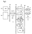
Fig. 5 stellt eine Variante der Schaltungsanordnung von Fig. 4 dar. Die wesentliche Änderung
besteht in einem dritten Bussystem 60, an das von den Netzwerk-Funktionseinheiten lediglich die
Netzwerkknoten 10, das DLL-RAM 20 und als neuen Schaltungsblock eine Prioritätslogik 55
angeschlossen sind. Die anderen Funktionseinheiten wie der Co-Prozessor 40, das HLL-RAM 21,
das Programm-RAM 41, die Direktzugriffseinheit 50.1 sowie der zweite Ein/Ausgang des DLL-RAM
20 sind an das zweite Bussystem 35 angeschlossen. Die Prioritätslogik 55 ist erforderlich,
weil der Co-Prozessor 40 nicht direkt mit dem dritten Bussystem 60 verbunden ist und somit bei
mehrfachem Zugriff von Netzwerkknoten 10, die Konfliktsteuerung nicht übernehmen kann. Ein
Vorteil dieser Anordnung ist, daß die Knoten 10 keine eigene DLL-RAM 10.7 bis 10.9 (vgl. Fig.
1) erfordern, weil das DLL-RAM 20 über das dritte Bussystem 60 gleichsam direkt an die
einzelnen Knoten 10.1, 10.4 angeschlossen ist. Mit dieser Anordnung ist leicht eine
Mehrfachausnutzung einzelner DLL-RAM-Bereiche möglich, indem mehrere Knoten 10 mit einer
einzigen DLL-Message verknüpfbar sind weil die Messages identisch sind.Fig. 5 shows a variant of the circuit arrangement of Fig. 4. The essential change
consists of a
In der Beschreibung enthaltene Bezeichnungen sind nicht als beschränkend anzusehen. Die Angabe von ROM und RAM schließt selbstverständlich andere Speicherarten nicht aus, beispielsweise die zunehmende Verwendung von löschbaren Speichern, z.B. "Flash"-Speichern, als Schreib-und-Lesespeicher, weil derartige Speicher die gespeicherte Information auch im im spannungslosen Zustand nicht verlieren. Für Aufgaben, bei denen die Spannungsversorgung nicht durchgehend gewährleistet ist, sind derartige Speicher von großem Vorteil. Im Kraftfahrzeug findet sich beispielsweise ein derartiger Anwendungsbereich, denn selbst bei einem batterieschonenden stand-by-Betrieb muss gelegentlich die Batterie gewechselt werden. The designations contained in the description are not to be regarded as restrictive. The Of course, specifying ROM and RAM does not exclude other types of memory, for example the increasing use of erasable memories, e.g. "Flash" memories, as read-write memory, because such memories store the information stored in the do not lose tension-free state. For tasks where the power supply is not is guaranteed continuously, such memories are of great advantage. In the motor vehicle there is such an area of application, for example, even with one Battery-saving stand-by operation requires the battery to be changed occasionally.
Betriebsdaten über Kilometerstand, vorgenommene Inspektionen usw. dürfen dabei nicht verloren gehen. Die Trennung der Netzfunktionen von den eigentlichen Prozessoraufgaben erlaubt auch ein sicheres Ablegen derartiger Daten in gesicherten Speicherbereichen des Hauptprozessors, die nicht auf einfache Weise zugänglich oder gar manipulierbar sind.Operating data on mileage, inspections, etc. must not be lost go. The separation of the network functions from the actual processor tasks also allows one safe storage of such data in secure memory areas of the main processor that are not are easily accessible or can even be manipulated.
Claims (5)
dem zweiten Bussystem (35) zugeordnet ist und eine zweite Direktzugriffseinrichtung (50.1) zwischen dem ersten und zweiten Bussystem (35 bzw. 30) einen direkten und damit raschen Zugriff des Hauptprozessors auf den zweiten Netzwerkspeicher ermöglicht.
is assigned to the second bus system (35) and a second direct access device (50.1) between the first and second bus system (35 or 30) enables the main processor to have direct and thus rapid access to the second network memory.
Priority Applications (2)
| Application Number | Priority Date | Filing Date | Title |
|---|---|---|---|
| EP01103440A EP1233346A1 (en) | 2001-02-14 | 2001-02-14 | Network co-processor for automotive vehicle |
| US10/077,472 US7260668B2 (en) | 2001-02-14 | 2002-02-14 | Network co-processor for vehicles |
Applications Claiming Priority (1)
| Application Number | Priority Date | Filing Date | Title |
|---|---|---|---|
| EP01103440A EP1233346A1 (en) | 2001-02-14 | 2001-02-14 | Network co-processor for automotive vehicle |
Publications (1)
| Publication Number | Publication Date |
|---|---|
| EP1233346A1 true EP1233346A1 (en) | 2002-08-21 |
Family
ID=8176489
Family Applications (1)
| Application Number | Title | Priority Date | Filing Date |
|---|---|---|---|
| EP01103440A Withdrawn EP1233346A1 (en) | 2001-02-14 | 2001-02-14 | Network co-processor for automotive vehicle |
Country Status (2)
| Country | Link |
|---|---|
| US (1) | US7260668B2 (en) |
| EP (1) | EP1233346A1 (en) |
Families Citing this family (6)
| Publication number | Priority date | Publication date | Assignee | Title |
|---|---|---|---|---|
| DE10157188A1 (en) * | 2001-11-22 | 2003-05-28 | G I N Mbh | Programmable data logger and classifier for CAN systems |
| EP1671214A4 (en) * | 2003-10-10 | 2010-01-27 | Nokia Corp | Microcontrol architecture for a system on a chip (soc) |
| US20060247833A1 (en) * | 2005-04-29 | 2006-11-02 | Anupam Malhotra | System and method for remote acquisition of automotive data from a vehicle |
| US20070260900A1 (en) * | 2006-05-03 | 2007-11-08 | Renesas Technology America, Inc. | High-performance microprocessor with lower-performance microcontroller in a vehicle network |
| US9459607B2 (en) | 2011-10-05 | 2016-10-04 | Opteon Corporation | Methods, apparatus, and systems for monitoring and/or controlling dynamic environments |
| CN106027350B (en) * | 2016-05-23 | 2022-01-21 | 株洲时代电子技术有限公司 | Design method of network control system of large road maintenance machine |
Citations (2)
| Publication number | Priority date | Publication date | Assignee | Title |
|---|---|---|---|---|
| WO1994015295A1 (en) * | 1992-12-22 | 1994-07-07 | Bull S.A. | System for data transmission between a computer bus and a network |
| US6175915B1 (en) * | 1998-08-11 | 2001-01-16 | Cisco Technology, Inc. | Data processor with trie traversal instruction set extension |
Family Cites Families (29)
| Publication number | Priority date | Publication date | Assignee | Title |
|---|---|---|---|---|
| US4604683A (en) * | 1984-12-10 | 1986-08-05 | Advanced Computer Communications | Communication controller using multiported random access memory |
| US5303344A (en) * | 1989-03-13 | 1994-04-12 | Hitachi, Ltd. | Protocol processing apparatus for use in interfacing network connected computer systems utilizing separate paths for control information and data transfer |
| JPH077955B2 (en) * | 1989-05-13 | 1995-01-30 | 株式会社東芝 | Data communication controller |
| JP2729420B2 (en) * | 1991-10-02 | 1998-03-18 | 三菱電機株式会社 | Communication processor |
| US5828856A (en) * | 1994-01-28 | 1998-10-27 | Apple Computer, Inc. | Dual bus concurrent multi-channel direct memory access controller and method |
| WO1996011440A1 (en) * | 1994-10-06 | 1996-04-18 | Virc, Inc. | Shared memory system |
| US5619726A (en) * | 1994-10-11 | 1997-04-08 | Intel Corporation | Apparatus and method for performing arbitration and data transfer over multiple buses |
| US5878217A (en) * | 1994-11-21 | 1999-03-02 | Cirrus Logic, Inc. | Network controller for switching into DMA mode based on anticipated memory overflow and out of DMA mode when the host processor is available |
| US5889816A (en) * | 1996-02-02 | 1999-03-30 | Lucent Technologies, Inc. | Wireless adapter architecture for mobile computing |
| US5896386A (en) * | 1997-01-31 | 1999-04-20 | Nec Usa, Inc. | Queue management method for wireless asynchronous transfer mode network interface card |
| US6151316A (en) * | 1997-02-14 | 2000-11-21 | Advanced Micro Devices, Inc. | Apparatus and method for synthesizing management packets for transmission between a network switch and a host controller |
| WO1999004343A1 (en) * | 1997-07-18 | 1999-01-28 | Interprophet Corporation | Tcp/ip network accelerator system and method |
| US6041058A (en) * | 1997-09-11 | 2000-03-21 | 3Com Corporation | Hardware filtering method and apparatus |
| US6658480B2 (en) * | 1997-10-14 | 2003-12-02 | Alacritech, Inc. | Intelligent network interface system and method for accelerated protocol processing |
| US6591302B2 (en) * | 1997-10-14 | 2003-07-08 | Alacritech, Inc. | Fast-path apparatus for receiving data corresponding to a TCP connection |
| US5937169A (en) * | 1997-10-29 | 1999-08-10 | 3Com Corporation | Offload of TCP segmentation to a smart adapter |
| US6424659B2 (en) * | 1998-07-17 | 2002-07-23 | Network Equipment Technologies, Inc. | Multi-layer switching apparatus and method |
| US6304973B1 (en) * | 1998-08-06 | 2001-10-16 | Cryptek Secure Communications, Llc | Multi-level security network system |
| US6526446B1 (en) * | 1999-04-27 | 2003-02-25 | 3Com Corporation | Hardware only transmission control protocol segmentation for a high performance network interface card |
| US6768992B1 (en) * | 1999-05-17 | 2004-07-27 | Lynne G. Jolitz | Term addressable memory of an accelerator system and method |
| US6427169B1 (en) * | 1999-07-30 | 2002-07-30 | Intel Corporation | Parsing a packet header |
| US6732255B1 (en) * | 1999-09-15 | 2004-05-04 | Koninklijke Philips Electronics N.V. | Can microcontroller that permits concurrent access to different segments of a common memory by both the processor core and the DMA engine thereof |
| US6308238B1 (en) * | 1999-09-24 | 2001-10-23 | Akamba Corporation | System and method for managing connections between clients and a server with independent connection and data buffers |
| JP3946393B2 (en) * | 1999-10-19 | 2007-07-18 | 株式会社東芝 | Parallel computer with hierarchical structure |
| US6968386B1 (en) * | 2000-01-06 | 2005-11-22 | International Business Machines Corporation | System for transferring data files between a user workstation and web server |
| US6865663B2 (en) * | 2000-02-24 | 2005-03-08 | Pts Corporation | Control processor dynamically loading shadow instruction register associated with memory entry of coprocessor in flexible coupling mode |
| US6629288B1 (en) * | 2000-03-01 | 2003-09-30 | Conexant Systems, Inc. | Single clock cycle CRC engine |
| US20060095723A1 (en) * | 2001-11-05 | 2006-05-04 | Moyer William C | Method and apparatus for interfacing a processor to a coprocessor |
| US6748479B2 (en) * | 2001-11-20 | 2004-06-08 | Broadcom Corporation | System having interfaces and switch that separates coherent and packet traffic |
-
2001
- 2001-02-14 EP EP01103440A patent/EP1233346A1/en not_active Withdrawn
-
2002
- 2002-02-14 US US10/077,472 patent/US7260668B2/en not_active Expired - Fee Related
Patent Citations (2)
| Publication number | Priority date | Publication date | Assignee | Title |
|---|---|---|---|---|
| WO1994015295A1 (en) * | 1992-12-22 | 1994-07-07 | Bull S.A. | System for data transmission between a computer bus and a network |
| US6175915B1 (en) * | 1998-08-11 | 2001-01-16 | Cisco Technology, Inc. | Data processor with trie traversal instruction set extension |
Non-Patent Citations (2)
| Title |
|---|
| "82596CA High-performance 32-bit local area network coprocessor", INTEL, October 1995 (1995-10-01), pages 1 - 76, XP002180320 * |
| R. OSBORNE ET AL: "DART - A Low Overhead ATM Network Interface Chip", MITSUBSHI TR-96-18, July 1996 (1996-07-01), pages 1 - 12, XP002180321 * |
Also Published As
| Publication number | Publication date |
|---|---|
| US20020120888A1 (en) | 2002-08-29 |
| US7260668B2 (en) | 2007-08-21 |
Similar Documents
| Publication | Publication Date | Title |
|---|---|---|
| EP2030116B1 (en) | Communication component | |
| DE69334165T2 (en) | NETWORK ADJUSTMENT DEVICE WITH MAIN COMPUTER INTERRUPTION AND INDICATION MANAGEMENT | |
| EP1776805B1 (en) | Flexray- communication component | |
| EP1776807B1 (en) | Method and device for accessing data of a message memory of a communication component | |
| EP1987642B1 (en) | Gateway for the automatic routing of messages between buses | |
| EP1787204B1 (en) | Message administrator and method for controlling access to data of the message memory of a communications component | |
| DE102005048581B4 (en) | Subscriber interface between a FlexRay communication module and a FlexRay subscriber and method for transmitting messages via such an interface | |
| WO2006079651A1 (en) | Method for transmitting data in messages via a communications link of a communications system and communications module, subscriber of a communications system and associated communications system | |
| DE102006058818A1 (en) | Apparatus and method for converting text messages | |
| EP2030118A1 (en) | Multi-processor gateway | |
| EP1776808B1 (en) | Method for storing messages in a message memory and corresponding message memory | |
| DE102021103064A1 (en) | Communication system | |
| EP0185260B1 (en) | Interface for direct information transfer | |
| EP1911213A1 (en) | Flexray communication module, flexray communication controller and a method for transmitting messages between a flexray communication connection and a flexray subscriber | |
| DE60305560T2 (en) | Embedded system for overload control of broadcast traffic in a communication network | |
| EP1233346A1 (en) | Network co-processor for automotive vehicle | |
| EP1370952B1 (en) | Communication method for establishing event channels in a timed communication system | |
| EP1099153B1 (en) | Storage device and a method for operating the storage device | |
| DE4447252A1 (en) | Multiplex transmission system via junctions | |
| WO1993005601A1 (en) | Data transmission process and data processing system with distributed computing nodes | |
| WO2005002145A1 (en) | Assembly and method for managing a memory | |
| DE102007049044A1 (en) | Data exchange device i.e. communication structure, for e.g. application specific integrated circuit, has function modules for processing interface-related functions, and master unit including number of signal inputs | |
| EP0528060B1 (en) | Procedure for input/output operations in computer systems | |
| EP1224540B1 (en) | Processor system, especially a processor system for communications devices | |
| DE4303741C2 (en) | Data transmission device |
Legal Events
| Date | Code | Title | Description |
|---|---|---|---|
| PUAI | Public reference made under article 153(3) epc to a published international application that has entered the european phase |
Free format text: ORIGINAL CODE: 0009012 |
|
| AK | Designated contracting states |
Kind code of ref document: A1 Designated state(s): AT BE CH CY DE DK ES FI FR GB GR IE IT LI LU MC NL PT SE TR |
|
| AX | Request for extension of the european patent |
Free format text: AL;LT;LV;MK;RO;SI |
|
| 17P | Request for examination filed |
Effective date: 20030221 |
|
| AKX | Designation fees paid |
Designated state(s): DE FR GB IT NL |
|
| 17Q | First examination report despatched |
Effective date: 20070802 |
|
| STAA | Information on the status of an ep patent application or granted ep patent |
Free format text: STATUS: THE APPLICATION IS DEEMED TO BE WITHDRAWN |
|
| 18D | Application deemed to be withdrawn |
Effective date: 20080213 |