EP1231972B1 - Elliptical wire-reinforced catheter - Google Patents
Elliptical wire-reinforced catheter Download PDFInfo
- Publication number
- EP1231972B1 EP1231972B1 EP00983678A EP00983678A EP1231972B1 EP 1231972 B1 EP1231972 B1 EP 1231972B1 EP 00983678 A EP00983678 A EP 00983678A EP 00983678 A EP00983678 A EP 00983678A EP 1231972 B1 EP1231972 B1 EP 1231972B1
- Authority
- EP
- European Patent Office
- Prior art keywords
- catheter
- wire
- main lumen
- reinforcing wire
- wires
- Prior art date
- Legal status (The legal status is an assumption and is not a legal conclusion. Google has not performed a legal analysis and makes no representation as to the accuracy of the status listed.)
- Revoked
Links
Images
Classifications
-
- A—HUMAN NECESSITIES
- A61—MEDICAL OR VETERINARY SCIENCE; HYGIENE
- A61M—DEVICES FOR INTRODUCING MEDIA INTO, OR ONTO, THE BODY; DEVICES FOR TRANSDUCING BODY MEDIA OR FOR TAKING MEDIA FROM THE BODY; DEVICES FOR PRODUCING OR ENDING SLEEP OR STUPOR
- A61M25/00—Catheters; Hollow probes
- A61M25/0043—Catheters; Hollow probes characterised by structural features
- A61M25/005—Catheters; Hollow probes characterised by structural features with embedded materials for reinforcement, e.g. wires, coils, braids
- A61M25/0053—Catheters; Hollow probes characterised by structural features with embedded materials for reinforcement, e.g. wires, coils, braids having a variable stiffness along the longitudinal axis, e.g. by varying the pitch of the coil or braid
Definitions
- the invention relates to wire-reinforced catheters used for detection and/or delivery of material to and from remote locations within the body of a patient. See for example US-A-5964971, which describes the closest prior art.
- Wire-reinforced catheters are well known in the art. Generally, these consist of an elongated, flexible tubular body defining a central lumen extending from one end of the body to the other end. The lumen communicates with the exterior of the body at the ends. In this manner, when a distal end of the catheter is implanted in the body of a patient, the lumen provides a conduit for delivery of material to or from the body, or for transfer of sensor information from within the interior of the body.
- the tubular body of the catheter is formed of a polymeric or other material, typically formed in layers.
- a polymeric or other material typically formed in layers.
- the winding pitch of the reinforcing wire can be varied along the length of the catheter to achieve a desired flexibility profile.
- One or more wires can be used, spirally wound in the same or opposite directions, extending partially or completely along the length of the catheter. Multiple, counter-woven strands thus used can be considered as forming a reinforcing wire mesh between the inner and outer layers of the catheter.
- the wires deployed in the prior art are either round or rectangular.
- One prior art device is the subject of U.S. Pat. No. 3,924,632 to Cook, disclosing a catheter 10 having inner (30) and outer (35) layers of plastic material such as polyethylene.
- a mesh of woven fiber glass bands 40, 41, 42, 43, 48, 49, 50 and 51 is disposed between these layers, the mesh comprising counter-rotated strands spirally wound around the exterior of inner layer 30.
- the strands are of 0.01 mm thickness.
- Layers 30 and 35 are heat bound to each other through the interstices of the fiber glass mesh.
- the distalmost portion comprises a meshless tube 52 bonded to the end.
- U.S. Patent No. 4,516,972 to Samson teaches the use of a ribbon reinforcement layer 16 disposed between an inner liner 12 and an outer layer 26 of a catheter 11.
- the ribbon is wound around inner liner 12 at varying pitches in order to achieve a specific flexibility profile in which proximal end portion 12a, intermediate portion 12b, and distal portion 12c each exhibit different flexibility.
- the ribbon is omitted altogether from a tip portion of the catheter 11 for maximum flexibility.
- One or two layers (17, 18) of ribbon can be used, counter rotated, with the second layer overlying the first layer.
- the ribbon material is preferably Kevlar.
- U.S. Patent No. 4,425,919 to Alston, Jr. et al. discloses a catheter 10 which is provided with a flat wire braid 14 disposed between an inner layer 12 and an outer layer 16.
- the inner layer 12 is made from a stretched, pre-oriented polyvinylidene fluoride or nylon 12.
- Outer layer 16 materials can be polyolefin polymers or ethyl vinyl acetate or polyurethane, adapted for sterilization by radiation.
- a flexible tip is provided by extending the outer layer beyond the inner layer and wire braid, so that the outer layer alone forms the tip and results in a more flexible structure.
- U.S. Patent No. 5,037,404 to Gold, et al. shows a catheter 10 having an inner layer 12 made from polyethylene, nylon, PVC, polyurethane or silicon rubber.
- Layer 12 is surrounded by a helically wound wire sheath 16 having a pair of counter rotated wires 18, 20 whose relative angle (i.e., pitch) can be varied to achieve desired torsional and longitudinal stiffness characteristics in different sections.
- the number of sections may be two or more, depending on the application, and the possibility of three sections is discussed.
- the wires 18, 20 can be braided, or they can be configured such that one overlies the other. Any desired wire cross-section may be used, and possible wire materials include stainless steel, nylon, and memory alloys such as Nitinol.
- U.S. Patent No. 5,069,674 to Fearnot, et al. shows the use of a spirally wound wire 105 to reinforce a catheter 100 comprised of an outer sheath 104 and an inner tube 401 (see Fig. 4).
- the coils of the wire 105 are loosely wound at the distal end of the catheter in order to achieve a more flexible structure at that end.
- the material of the wire 105 is hardened stainless steel "or other metals or alloys", while the material of the outer sheath 104 can be polyamide, fluoropolymers, TEFLONTM or other copolymer plastics.
- U.S. Patent No. 5,279,596 to Castaneda, et al. shows a catheter 10 having a distal portion 22 which is more flexible than a proximal portion 14. In both portions a support wire is embedded. Wire 28 of the distal portion is preferably of rectangular cross-section and is made of stainless steel. Structurally, wire 28 coaxially surrounds an inner layer 26 and is embedded in an overlaying outer layer 24 (see Fig. 4). Inner layer 26 is formed of PTFE, while outer layer 24 is formed of nylon.
- the relative difference in flexibility between distal portion 22 and proximal portion 14 is achieved using appropriate materials selection, particularly, by selecting for the outer layer of the distal portion a material with a lower Shore D durometer rating (a rating of 40 is mentioned in col. 3, 11. 63-64) than that of the outer portion of the proximal portion.
- U.S. Patent No. 5,176,660 to Truckai, et al. discusses the Gold, et al. patent (see above) and its teachings are specifically held out as an extension of the concepts of the Gold, et al. patent.
- a catheter 10 is provided with an inner layer 12 made of polyethylene, nylon, PVC, polyurethane, or silicon rubber.
- a tubular braided wire sheath 16 is formed over inner layer 12.
- the braided wire sheath 16 comprises a pair of counter rotating helical strands 18,20 of flat wire made from spring steel. Nitinol is also discussed, in col. 4, 1. 40.
- an outer layer 22 made of the same material as the inner layer, as seen from Fig. 5.
- the angle strands 18 and 20 make with each other can be varied in different segments of the catheter 10 to achieve varying physical characteristics, as discussed in col. 3, 11. 17-19 and col. 4, 11. 21-23. These characteristics include stiffness/flexibility.
- U.S. Patents Nos. 5,454,795, 5,695,483 and 5,876,386 to Satnson describe a catheter in which one or more stiffener ribbons (274) are used to reinforce the tubular body (270) of the catheter and control flexibility.
- the stiffener ribbons are selectively applied in varying pitches and turn directions ("handedness") in order to tailor the catheter flexibility profile to specific applications.
- the catheter is constructed to have the stiffener ribbons sandwiched between inner and outer tubular polymer layers, referred to respectively as an inner tubular liner (272) and outer tubular cover (276).
- the ribbons are described as rectangular in cross section, having dimensions of between 0.018 mm and 0.038 mm in thickness and between 0.063 mm and 0.20 mm in width. Alternatively, depending on the ribbon material, thickness and width dimensions of 0.01 mm and 0.025 mm, respectively, are mentioned.
- the tubular polymer layers comprise compatible materials designed to adhere to each other with or without the aid of a suitable adhesive.
- the present invention provides a catheter having a reinforcing wire whose cross sectional shape is oval or elliptical. In this manner, the potentially problematic sharp edges of the rectangular reinforcing wire of the prior art are avoided. Moreover, the wire is not round in cross section, thus providing improved functional and dimensional performance over the known prior art.
- a catheter having a substantially tubular body in which a main lumen is formed is provided with a helically wound reinforcing wire in at least a portion thereof.
- This portion may be the distalmost, implantable portion of the catheter, or it may be a different portion or the entirety of the catheter.
- the tubular body comprises inner and outer layers of identical or different materials between which the reinforcing wire is helically wound.
- the reinforcing wire is selected to have an oval or elliptical cross section, thereby reducing the potential for damage to the inner and outer layers of the catheter due to the presence of sharp edges. Additionally, the oval or elliptical cross sectional shape affords the advantages of a smaller profile and improved performance, compared to bulkier and less suitable conventional round wire devices.
- the winding configuration selected in the catheter of the present invention is a function of the desired catheter flexibility profile, with a higher winding pitch being used to impart greater flexibility. Additionally, flexibility can be controlled through judicious selection of the materials for the reinforcing wire and the inner and outer layers.
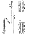
- FIG. 1 shows diagrammatically a catheter 10 in accordance with the present invention.
- Catheter 10 is an elongate, generally tubular structure having a proximal portion 12 and a distal portion 14.
- a fitting, designated generally as 16, is disposed at proximal portion 12 and serves to interface the catheter 10 with various support and delivery devices, depending on the contemplated application of the catheter.
- Catheter 10 in operation is introduced into the body of a patient (not shown) such that the distal portion 14 is guided, using for instance a guidewire (not shown), to a target site within the body for performance of a needed procedure, such as localized delivery of medicament to the site.
- Proximal portion 12 remains exterior to the patient and provides access, via a main lumen (as described below), to the site within the patient's body.
- FIG. 1A is a partial sectional view of a segment 20 of catheter 10 in accordance with the invention.
- Segment 20 is an exemplary portion of the catheter 10, such that the structure of segment 20 as described can be specific to a prescribed portion of the catheter, such as distal portion 14, or can be illustrative of the construction of the entire length of the catheter.
- Segment 20 comprises a main lumen 22 extending longitudinally along the segment length and defined by an inner layer 26 and an outer layer 24.
- Main lumen 22 extends substantially the entire length of catheter 10, from proximal portion 12 to distal portion 14, and is in communication with the exterior of the catheter at least at these portions and/or in their vicinity.
- Lumen 22 serves to convey materials between proximal portion 12 and distal portion 14 of catheter 10, which materials include but are not limited to nutrition, medicaments, contrast media, liquid embolizing agents, blood, guidewires and other devices such as sensors and sensor information-carrying conductors.
- Layers 24 and 26 are generally tubular in shape, resulting in a generally tubular segment 20 and catheter 10.
- Numeral 28 represents a reinforcing wire overlying inner layer 26 and covered by outer layer 24.
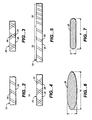
- Wire 28 is preferably disposed in a helical pattern, illustrated diagrammatically in FIG. 2. Other patterns are also possible, as illustrated in FIGS. 3-5.
- FIG. 3 two wire strands are used, one overlying the other.
- wire 28 is wrapped around inner layer 26 and around a second, inner wire 30.
- Wires 28 and 30 can be wound in the opposite directions, as depicted in FIG. 3, or they can be wound in the same direction and offset such that one wire is disposed between the other wire to provide a denser weave pattern ⁇ that is, a higher pitch (not shown).
- FIG. 3 In FIG.
- segment 20 is shown as divided into two segments, 32 and 34, each having the wire 28 wound at a different pitch over inner layer 26. Different pitches are used to selectively control flexibility of different portions of catheter 10. Moreover, in some constructions combinations of the above patterns can be used, in different segments or within the same segment, depending on the desired characteristics.
- the catheter 10 can be constructed of a single layer 36.
- reinforcing wire 28 is embedded in layer 36 using standard manufacturing techniques.
- FIG. 2A depicts such an arrangement.
- An important feature of the present invention is the cross-sectional shape of the wires 28 and 30.
- an elliptical or oval shape is selected.
- FIGS. 6 and 7 depict such shapes. It will appreciated that adherence to strict definitions of elliptical-that is, in the conic curve sense-is not intended, and some deviation is contemplated.
- the term "wire” is not intended to designate an electrically conductive material or a metallic material, although the latter construction is in fact preferred. For purposes of completion, however, it will appreciated that a suitable polymeric material or other non-metallic materials fall within the purview of the present invention.
- the wire have a thickness t of between about 0.01 mm to about 0.1 mm and a width w of between about 0.038 mm to about 0.38 mm
- Other dimensional combinations for the wire can be a thickness of about 0.01 mm and a width of about 0.038 mm a thickness of about 0.03 mm and a width of about 0.08 mm a thickness of about 0.05 mm and a width of about 0.20 mm or a thickness of about 0.1 mm and a width of about 0.38 mm.
- Other dimensional combinations are also contemplated and it is not intended that the invention be limited to those enumerated above.
- Catheter 10 is constructed from materials which are well known in the art and which are governed by the particular application with a view to for example the flexibility and torquability requirements, along with the particular procedure to be performed on the patient, patient size and condition, and the materials to be delivered to the target site in the patient's body. It is preferred that the catheter be constructed to meet certain minimal physical criteria. Specifically, for many applications it is preferred that the distal portion of the catheter adhere to a critical bend diameter constraint of no more than about 1.50 mm and exhibit a lateral stiffness of greater than about 7.3°/cm-g deflection measured by a Tinius-Olsen Stiffness Tester at 20°-30° of deflection.
Landscapes
- Health & Medical Sciences (AREA)
- Life Sciences & Earth Sciences (AREA)
- Biomedical Technology (AREA)
- Pulmonology (AREA)
- Engineering & Computer Science (AREA)
- Anesthesiology (AREA)
- Biophysics (AREA)
- Heart & Thoracic Surgery (AREA)
- Hematology (AREA)
- Animal Behavior & Ethology (AREA)
- General Health & Medical Sciences (AREA)
- Public Health (AREA)
- Veterinary Medicine (AREA)
- Media Introduction/Drainage Providing Device (AREA)
- Materials For Medical Uses (AREA)
Abstract
Description
- The invention relates to wire-reinforced catheters used for detection and/or delivery of material to and from remote locations within the body of a patient. See for example US-A-5964971, which describes the closest prior art.
- Wire-reinforced catheters are well known in the art. Generally, these consist of an elongated, flexible tubular body defining a central lumen extending from one end of the body to the other end. The lumen communicates with the exterior of the body at the ends. In this manner, when a distal end of the catheter is implanted in the body of a patient, the lumen provides a conduit for delivery of material to or from the body, or for transfer of sensor information from within the interior of the body.
- Structurally, the tubular body of the catheter is formed of a polymeric or other material, typically formed in layers. One arrangement, of particular interest here, contemplates a structure in which an inner layer is surrounded by a wound reinforcing wire. Atop this reinforcing wire is overlaid an outer layer, such that the reinforcing wire is sandwiched between the inner and outer layers. The winding pitch of the reinforcing wire can be varied along the length of the catheter to achieve a desired flexibility profile. One or more wires can be used, spirally wound in the same or opposite directions, extending partially or completely along the length of the catheter. Multiple, counter-woven strands thus used can be considered as forming a reinforcing wire mesh between the inner and outer layers of the catheter. In cross section, the wires deployed in the prior art are either round or rectangular.
- One prior art device is the subject of U.S. Pat. No. 3,924,632 to Cook, disclosing a
catheter 10 having inner (30) and outer (35) layers of plastic material such as polyethylene. A mesh of woven fiber glass bands 40, 41, 42, 43, 48, 49, 50 and 51 is disposed between these layers, the mesh comprising counter-rotated strands spirally wound around the exterior ofinner layer 30. The strands are of 0.01 mm thickness.Layers 30 and 35 are heat bound to each other through the interstices of the fiber glass mesh. To provide maximal flexibility at the tip ofcatheter 10, the distalmost portion comprises a meshless tube 52 bonded to the end. - U.S. Patent No. 4,516,972 to Samson teaches the use of a
ribbon reinforcement layer 16 disposed between aninner liner 12 and anouter layer 26 of a catheter 11. The ribbon is wound aroundinner liner 12 at varying pitches in order to achieve a specific flexibility profile in which proximal end portion 12a, intermediate portion 12b, and distal portion 12c each exhibit different flexibility. The ribbon is omitted altogether from a tip portion of the catheter 11 for maximum flexibility. One or two layers (17, 18) of ribbon can be used, counter rotated, with the second layer overlying the first layer. The ribbon material is preferably Kevlar. - U.S. Patent No. 4,425,919 to Alston, Jr. et al. discloses a
catheter 10 which is provided with a flat wire braid 14 disposed between aninner layer 12 and anouter layer 16. Theinner layer 12 is made from a stretched, pre-oriented polyvinylidene fluoride ornylon 12.Outer layer 16 materials can be polyolefin polymers or ethyl vinyl acetate or polyurethane, adapted for sterilization by radiation. A flexible tip is provided by extending the outer layer beyond the inner layer and wire braid, so that the outer layer alone forms the tip and results in a more flexible structure. - U.S. Patent No. 5,037,404 to Gold, et al. shows a
catheter 10 having aninner layer 12 made from polyethylene, nylon, PVC, polyurethane or silicon rubber.Layer 12 is surrounded by a helicallywound wire sheath 16 having a pair of counter rotatedwires 18, 20 whose relative angle (i.e., pitch) can be varied to achieve desired torsional and longitudinal stiffness characteristics in different sections. The number of sections may be two or more, depending on the application, and the possibility of three sections is discussed. Thewires 18, 20 can be braided, or they can be configured such that one overlies the other. Any desired wire cross-section may be used, and possible wire materials include stainless steel, nylon, and memory alloys such as Nitinol. - U.S. Patent No. 5,069,674 to Fearnot, et al. shows the use of a spirally wound wire 105 to reinforce a catheter 100 comprised of an outer sheath 104 and an inner tube 401 (see Fig. 4). The coils of the wire 105 are loosely wound at the distal end of the catheter in order to achieve a more flexible structure at that end. The material of the wire 105 is hardened stainless steel "or other metals or alloys", while the material of the outer sheath 104 can be polyamide, fluoropolymers, TEFLON™ or other copolymer plastics.
- U.S. Patent No. 5,279,596 to Castaneda, et al. shows a
catheter 10 having a distal portion 22 which is more flexible than a proximal portion 14. In both portions a support wire is embedded.Wire 28 of the distal portion is preferably of rectangular cross-section and is made of stainless steel. Structurally,wire 28 coaxially surrounds aninner layer 26 and is embedded in an overlaying outer layer 24 (see Fig. 4).Inner layer 26 is formed of PTFE, whileouter layer 24 is formed of nylon. The relative difference in flexibility between distal portion 22 and proximal portion 14 is achieved using appropriate materials selection, particularly, by selecting for the outer layer of the distal portion a material with a lower Shore D durometer rating (a rating of 40 is mentioned in col. 3, 11. 63-64) than that of the outer portion of the proximal portion. - U.S. Patent No. 5,176,660 to Truckai, et al., discusses the Gold, et al. patent (see above) and its teachings are specifically held out as an extension of the concepts of the Gold, et al. patent. In Truckai, a
catheter 10 is provided with aninner layer 12 made of polyethylene, nylon, PVC, polyurethane, or silicon rubber. A tubular braidedwire sheath 16 is formed overinner layer 12. The braidedwire sheath 16 comprises a pair of counter rotatinghelical strands 18,20 of flat wire made from spring steel. Nitinol is also discussed, in col. 4, 1. 40. Over the braidedwire sheath 16 and bonded with theinner layer 12 via the interstices of the sheath is an outer layer 22, made of the same material as the inner layer, as seen from Fig. 5. Theangle strands 18 and 20 make with each other can be varied in different segments of thecatheter 10 to achieve varying physical characteristics, as discussed in col. 3, 11. 17-19 and col. 4, 11. 21-23. These characteristics include stiffness/flexibility. - U.S. Patents Nos. 5,454,795, 5,695,483 and 5,876,386 to Satnson describe a catheter in which one or more stiffener ribbons (274) are used to reinforce the tubular body (270) of the catheter and control flexibility. The stiffener ribbons are selectively applied in varying pitches and turn directions ("handedness") in order to tailor the catheter flexibility profile to specific applications. The catheter is constructed to have the stiffener ribbons sandwiched between inner and outer tubular polymer layers, referred to respectively as an inner tubular liner (272) and outer tubular cover (276). The ribbons are described as rectangular in cross section, having dimensions of between 0.018 mm and 0.038 mm in thickness and between 0.063 mm and 0.20 mm in width. Alternatively, depending on the ribbon material, thickness and width dimensions of 0.01 mm and 0.025 mm, respectively, are mentioned. The tubular polymer layers comprise compatible materials designed to adhere to each other with or without the aid of a suitable adhesive.
- The above-described prior art references are herein incorporated by reference in their entirety.
- The prior art has been found to suffer from shortcomings due to the cross-sectional shape of the reinforcing wires used. Specifically, the use of round wire fails to provide the desired stiffness control, and requires wires whose thickness is dimensionally incompatible with the design and size requirements for many applications. Rectangular cross section wires, on the other hand, have sharp edges which can cause damage to the tubular body of the catheter during manufacture and/or use.
- To overcome the deficiencies of the prior art, the present invention provides a catheter having a reinforcing wire whose cross sectional shape is oval or elliptical. In this manner, the potentially problematic sharp edges of the rectangular reinforcing wire of the prior art are avoided. Moreover, the wire is not round in cross section, thus providing improved functional and dimensional performance over the known prior art.
- In accordance with the present invention, a catheter having a substantially tubular body in which a main lumen is formed is provided with a helically wound reinforcing wire in at least a portion thereof. This portion may be the distalmost, implantable portion of the catheter, or it may be a different portion or the entirety of the catheter. The tubular body comprises inner and outer layers of identical or different materials between which the reinforcing wire is helically wound. The reinforcing wire is selected to have an oval or elliptical cross section, thereby reducing the potential for damage to the inner and outer layers of the catheter due to the presence of sharp edges. Additionally, the oval or elliptical cross sectional shape affords the advantages of a smaller profile and improved performance, compared to bulkier and less suitable conventional round wire devices.
- The winding configuration selected in the catheter of the present invention is a function of the desired catheter flexibility profile, with a higher winding pitch being used to impart greater flexibility. Additionally, flexibility can be controlled through judicious selection of the materials for the reinforcing wire and the inner and outer layers.
- Many advantages of the present invention will be apparent to those skilled in the art with a reading of this specification in conjunction with the attached drawings, wherein like reference numerals are applied to like elements and wherein:
- FIG. 1 is a diagrammatical view of a catheter in accordance with the invention;
- FIG. 1A is a sectional view of a segment of the catheter of FIG. 1;
- FIG. 2 is a schematic view showing a first reinforcing wire winding configuration;
- FIG. 2A is a sectional view of an alternative embodiment of a segment of the catheter of FIG. 1;
- FIG. 3 is a schematic view showing a second reinforcing wire winding configuration;
- FIG. 4 is a schematic view showing a third reinforcing wire winding configuration;
- FIG. 5 is a schematic view showing a fourth reinforcing wire winding configuration;
- FIG. 6 is a cross-sectional view depicting a first exemplary reinforcing wire shape in accordance with the invention; and
- FIG. 7 is a cross-sectional view depicting a second exemplary reinforcing wire shape in accordance with the invention.
- FIG. 1 shows diagrammatically a
catheter 10 in accordance with the present invention.Catheter 10 is an elongate, generally tubular structure having aproximal portion 12 and a distal portion 14. A fitting, designated generally as 16, is disposed atproximal portion 12 and serves to interface thecatheter 10 with various support and delivery devices, depending on the contemplated application of the catheter.Catheter 10 in operation is introduced into the body of a patient (not shown) such that the distal portion 14 is guided, using for instance a guidewire (not shown), to a target site within the body for performance of a needed procedure, such as localized delivery of medicament to the site.Proximal portion 12 remains exterior to the patient and provides access, via a main lumen (as described below), to the site within the patient's body. - FIG. 1A is a partial sectional view of a
segment 20 ofcatheter 10 in accordance with the invention.Segment 20 is an exemplary portion of thecatheter 10, such that the structure ofsegment 20 as described can be specific to a prescribed portion of the catheter, such as distal portion 14, or can be illustrative of the construction of the entire length of the catheter.Segment 20 comprises a main lumen 22 extending longitudinally along the segment length and defined by aninner layer 26 and anouter layer 24. Main lumen 22 extends substantially the entire length ofcatheter 10, fromproximal portion 12 to distal portion 14, and is in communication with the exterior of the catheter at least at these portions and/or in their vicinity. Lumen 22 serves to convey materials betweenproximal portion 12 and distal portion 14 ofcatheter 10, which materials include but are not limited to nutrition, medicaments, contrast media, liquid embolizing agents, blood, guidewires and other devices such as sensors and sensor information-carrying conductors.Layers tubular segment 20 andcatheter 10. -
Numeral 28 represents a reinforcing wire overlyinginner layer 26 and covered byouter layer 24.Wire 28 is preferably disposed in a helical pattern, illustrated diagrammatically in FIG. 2. Other patterns are also possible, as illustrated in FIGS. 3-5. In FIG. 3, two wire strands are used, one overlying the other. Specifically, in FIG. 3,wire 28 is wrapped aroundinner layer 26 and around a second,inner wire 30.Wires wires inner layer 26. In FIG. 5,segment 20 is shown as divided into two segments, 32 and 34, each having thewire 28 wound at a different pitch overinner layer 26. Different pitches are used to selectively control flexibility of different portions ofcatheter 10. Moreover, in some constructions combinations of the above patterns can be used, in different segments or within the same segment, depending on the desired characteristics. - It is also contemplated that the
catheter 10 can be constructed of asingle layer 36. In such a construction, reinforcingwire 28 is embedded inlayer 36 using standard manufacturing techniques. FIG. 2A depicts such an arrangement. - An important feature of the present invention is the cross-sectional shape of the
wires - Dimensionally, it is contemplated that the wire have a thickness t of between about 0.01 mm to about 0.1 mm and a width w of between about 0.038 mm to about 0.38 mm Other dimensional combinations for the wire can be a thickness of about 0.01 mm and a width of about 0.038 mm a thickness of about 0.03 mm and a width of about 0.08 mm a thickness of about 0.05 mm and a width of about 0.20 mm or a thickness of about 0.1 mm and a width of about 0.38 mm. Other dimensional combinations are also contemplated and it is not intended that the invention be limited to those enumerated above.
-
Catheter 10 is constructed from materials which are well known in the art and which are governed by the particular application with a view to for example the flexibility and torquability requirements, along with the particular procedure to be performed on the patient, patient size and condition, and the materials to be delivered to the target site in the patient's body. It is preferred that the catheter be constructed to meet certain minimal physical criteria. Specifically, for many applications it is preferred that the distal portion of the catheter adhere to a critical bend diameter constraint of no more than about 1.50 mm and exhibit a lateral stiffness of greater than about 7.3°/cm-g deflection measured by a Tinius-Olsen Stiffness Tester at 20°-30° of deflection. - The above are exemplary modes of carrying out the invention and are not intended to be limiting. It will be apparent to those of ordinary skill in the art that modifications thereto can be made without departure from the scope of the invention.
Claims (15)
- A catheter (10) comprising:a substantially elongated structure having a proximal portion (12), a distal portion (14), and exterior, and defining a main lumen (22) having a central axis and extending between the proximal and distal portions (12, 14), the main lumen (22) being in communication with the exterior of the elongated structure at least at said proximal and distal portions (12, 14);characterized in that the main lumen has a continuous tubular inner surface, in that the catheter has a continuous outer surface, and in that the catheter also comprises a reinforcing wire (28, 30) having a cross section selected from oval and elliptical surrounding the main lumen (22) along at least a segment (20) of the substantially elongated structure, andwherein the distal portion (14) of the catheter (10) exhibits a lateral stiffness represented by a deflection of greater than about 7.3°/cm-g measured by a Tinius-Olsen Stiffness Tester at 20°-30° of deflection.
- A catheter (10) according to claim 1, wherein the substantially elongated structure comprises:- an inner layer (26) having the continuous tubular inner surface defining the main lumen (22); and- an outer layer (24) surrounding the inner layer (26) and having the continuous outer surface,
wherein the reinforcing wire (28, 30) is disposed between the inner and outer layers (26, 24). - A catheter (10) according to claim 1, wherein the substantially elongated structure comprises a single layer (36) in which the reinforcing wire (28, 30) is embedded, said single layer having the continuous tubular inner surface defining the main lumen and having the continuous outer surface.
- A catheter (10) according to any of claims 1 to 3, wherein said reinforcing wire (28, 30) has a thickness (t) of about 0.01 mm to about 0.1 mm, and a width (w) of about 0.038 mm to 0.38 mm.
- A catheter (10) according to any of claims 1-4, wherein the reinforcing wire (28, 30) is helically wound around the main lumen (22) along the segment (20).
- A catheter (10) according to claim 5, wherein the helical winding is of varying pitches.
- A catheter (10) according to any of claims 1-6, wherein the reinforcing wires (28, 30) comprise two wires (28, 30).
- A catheter (10) according to claim 7, wherein the two wires (28, 30) are wound in opposite directions about the main lumen (22) along the segment (20).
- A catheter (10) according to claim 7, wherein the two wires (28, 30) are interwoven.
- A catheter (10) according to any of claims 1-9, wherein the distal portion (14) of the catheter (10) exhibits a critical bend diameter of no more than about 1.50 mm.
- A catheter (10) according to any of claims 1-10, wherein the reinforcing wire (28, 30) has a thickness (t) of about 0.01 mm and a width (w) of about 0.038 mm.
- A catheter (10) according to any of claims 1-10, wherein the reinforcing wire (28, 30) has a thickness (t) of about 0.03 mm and a width (w) of about 0.08 mm.
- A catheter (10) according to any of claims 1-10, wherein the reinforcing wire (28, 30) has a thickness (t) of about 0.05 mm and a width (w) of about 0.08 mm.
- A catheter (10) according to claims 1, 5, 6, 7, 8, or 9, wherein the wire cross-section is an oval cross-section.
- A catheter (10) according to claims 1, 5, 6, 7, 8, or 9, wherein the wire cross-section is an elliptical cross-section.
Applications Claiming Priority (3)
| Application Number | Priority Date | Filing Date | Title |
|---|---|---|---|
| US16761399P | 1999-11-26 | 1999-11-26 | |
| US167613P | 1999-11-26 | ||
| PCT/US2000/030157 WO2001037918A1 (en) | 1999-11-26 | 2000-11-24 | Elliptical wire-reinforced catheter |
Publications (2)
| Publication Number | Publication Date |
|---|---|
| EP1231972A1 EP1231972A1 (en) | 2002-08-21 |
| EP1231972B1 true EP1231972B1 (en) | 2006-01-18 |
Family
ID=22608067
Family Applications (1)
| Application Number | Title | Priority Date | Filing Date |
|---|---|---|---|
| EP00983678A Revoked EP1231972B1 (en) | 1999-11-26 | 2000-11-24 | Elliptical wire-reinforced catheter |
Country Status (8)
| Country | Link |
|---|---|
| EP (1) | EP1231972B1 (en) |
| JP (1) | JP2003514633A (en) |
| AT (1) | ATE315949T1 (en) |
| AU (1) | AU2040601A (en) |
| CA (1) | CA2389933A1 (en) |
| DE (1) | DE60025649T2 (en) |
| ES (1) | ES2256073T3 (en) |
| WO (1) | WO2001037918A1 (en) |
Families Citing this family (6)
| Publication number | Priority date | Publication date | Assignee | Title |
|---|---|---|---|---|
| JP4924418B2 (en) * | 2005-02-10 | 2012-04-25 | 株式会社カネカ | Medical catheter tube and manufacturing method thereof |
| US7914515B2 (en) | 2007-07-18 | 2011-03-29 | St. Jude Medical, Atrial Fibrillation Division, Inc. | Catheter and introducer catheter having torque transfer layer and method of manufacture |
| US20120078187A1 (en) * | 2010-09-23 | 2012-03-29 | Cook Incorporated | Flexible introducer sheath |
| CN111437490A (en) | 2013-05-19 | 2020-07-24 | 卡迪纳尔健康515瑞士有限公司 | Large lumen guiding catheter |
| US9242079B2 (en) * | 2013-11-12 | 2016-01-26 | Gyrus Acmi, Inc. | Ureteral stents with waveform interlayers and interstitching |
| JP2016084901A (en) * | 2014-10-28 | 2016-05-19 | 日星電気株式会社 | Tubular element |
Family Cites Families (12)
| Publication number | Priority date | Publication date | Assignee | Title |
|---|---|---|---|---|
| US3924632A (en) | 1972-12-07 | 1975-12-09 | William A Cook | Fiber glass reinforced catheter |
| US4425919A (en) | 1981-07-27 | 1984-01-17 | Raychem Corporation | Torque transmitting catheter apparatus |
| US4516972A (en) | 1982-01-28 | 1985-05-14 | Advanced Cardiovascular Systems, Inc. | Guiding catheter and method of manufacture |
| US5037404A (en) | 1988-11-14 | 1991-08-06 | Cordis Corporation | Catheter having sections of variable torsion characteristics |
| US4985022A (en) | 1988-11-23 | 1991-01-15 | Med Institute, Inc. | Catheter having durable and flexible segments |
| US5176660A (en) | 1989-10-23 | 1993-01-05 | Cordis Corporation | Catheter having reinforcing strands |
| US5279596A (en) | 1990-07-27 | 1994-01-18 | Cordis Corporation | Intravascular catheter with kink resistant tip |
| US5454795A (en) | 1994-06-27 | 1995-10-03 | Target Therapeutics, Inc. | Kink-free spiral-wound catheter |
| AU4242996A (en) * | 1994-11-23 | 1996-06-17 | Navarre Biomedical, Ltd. | Flexible catheter |
| US5713867A (en) * | 1996-04-29 | 1998-02-03 | Medtronic, Inc. | Introducer system having kink resistant splittable sheath |
| US5755704A (en) * | 1996-10-29 | 1998-05-26 | Medtronic, Inc. | Thinwall guide catheter |
| US5951539A (en) * | 1997-06-10 | 1999-09-14 | Target Therpeutics, Inc. | Optimized high performance multiple coil spiral-wound vascular catheter |
-
2000
- 2000-11-24 JP JP2001539529A patent/JP2003514633A/en active Pending
- 2000-11-24 EP EP00983678A patent/EP1231972B1/en not_active Revoked
- 2000-11-24 DE DE60025649T patent/DE60025649T2/en not_active Revoked
- 2000-11-24 AU AU20406/01A patent/AU2040601A/en not_active Abandoned
- 2000-11-24 ES ES00983678T patent/ES2256073T3/en not_active Expired - Lifetime
- 2000-11-24 WO PCT/US2000/030157 patent/WO2001037918A1/en active IP Right Grant
- 2000-11-24 CA CA002389933A patent/CA2389933A1/en not_active Abandoned
- 2000-11-24 AT AT00983678T patent/ATE315949T1/en not_active IP Right Cessation
Also Published As
| Publication number | Publication date |
|---|---|
| WO2001037918A9 (en) | 2002-05-16 |
| WO2001037918A1 (en) | 2001-05-31 |
| ES2256073T3 (en) | 2006-07-16 |
| DE60025649T2 (en) | 2006-11-02 |
| DE60025649D1 (en) | 2006-04-06 |
| JP2003514633A (en) | 2003-04-22 |
| CA2389933A1 (en) | 2001-05-31 |
| AU2040601A (en) | 2001-06-04 |
| EP1231972A1 (en) | 2002-08-21 |
| ATE315949T1 (en) | 2006-02-15 |
Similar Documents
| Publication | Publication Date | Title |
|---|---|---|
| JP3224501B2 (en) | High performance spiral wound catheter | |
| US7985214B2 (en) | Intravascular catheter with composite reinforcement | |
| US5891112A (en) | High performance superelastic alloy braid reinforced catheter | |
| EP0782463B1 (en) | High performance braided catheter | |
| EP1019132B1 (en) | Soft-tip high performance braided catheter | |
| US5951539A (en) | Optimized high performance multiple coil spiral-wound vascular catheter | |
| US6824553B1 (en) | High performance braided catheter | |
| EP0930910B1 (en) | Guide catheter with enhanced guidewire tracking | |
| US6152912A (en) | Optimized high performance spiral-wound vascular catheter | |
| JP4009324B2 (en) | Reinforced catheter with a moldable distal tip | |
| US6629952B1 (en) | High pressure vascular balloon catheter | |
| US6709429B1 (en) | Intravascular catheter with multiple axial fibers | |
| US20030191451A1 (en) | Reinforced catheter system | |
| US6942654B1 (en) | Intravascular catheter with axial member | |
| JP2001518368A (en) | Peripheral vascular delivery catheter | |
| EP1152788A1 (en) | Intravascular catheter with composite reinforcement | |
| EP1231972B1 (en) | Elliptical wire-reinforced catheter | |
| US10821264B1 (en) | Mixed coil catheter and process for making same | |
| WO2003086519A1 (en) | Reinforced catheter system |
Legal Events
| Date | Code | Title | Description |
|---|---|---|---|
| PUAI | Public reference made under article 153(3) epc to a published international application that has entered the european phase |
Free format text: ORIGINAL CODE: 0009012 |
|
| 17P | Request for examination filed |
Effective date: 20020507 |
|
| AK | Designated contracting states |
Kind code of ref document: A1 Designated state(s): AT BE CH CY DE DK ES FI FR GB GR IE IT LI LU MC NL PT SE TR |
|
| AX | Request for extension of the european patent |
Free format text: AL;LT;LV;MK;RO;SI |
|
| 17Q | First examination report despatched |
Effective date: 20031111 |
|
| GRAP | Despatch of communication of intention to grant a patent |
Free format text: ORIGINAL CODE: EPIDOSNIGR1 |
|
| GRAS | Grant fee paid |
Free format text: ORIGINAL CODE: EPIDOSNIGR3 |
|
| GRAA | (expected) grant |
Free format text: ORIGINAL CODE: 0009210 |
|
| AK | Designated contracting states |
Kind code of ref document: B1 Designated state(s): AT BE CH CY DE DK ES FI FR GB GR IE IT LI LU MC NL PT SE TR |
|
| PG25 | Lapsed in a contracting state [announced via postgrant information from national office to epo] |
Ref country code: IT Free format text: LAPSE BECAUSE OF FAILURE TO SUBMIT A TRANSLATION OF THE DESCRIPTION OR TO PAY THE FEE WITHIN THE PRESCRIBED TIME-LIMIT;WARNING: LAPSES OF ITALIAN PATENTS WITH EFFECTIVE DATE BEFORE 2007 MAY HAVE OCCURRED AT ANY TIME BEFORE 2007. THE CORRECT EFFECTIVE DATE MAY BE DIFFERENT FROM THE ONE RECORDED. Effective date: 20060118 Ref country code: FI Free format text: LAPSE BECAUSE OF FAILURE TO SUBMIT A TRANSLATION OF THE DESCRIPTION OR TO PAY THE FEE WITHIN THE PRESCRIBED TIME-LIMIT Effective date: 20060118 Ref country code: BE Free format text: LAPSE BECAUSE OF FAILURE TO SUBMIT A TRANSLATION OF THE DESCRIPTION OR TO PAY THE FEE WITHIN THE PRESCRIBED TIME-LIMIT Effective date: 20060118 Ref country code: CH Free format text: LAPSE BECAUSE OF FAILURE TO SUBMIT A TRANSLATION OF THE DESCRIPTION OR TO PAY THE FEE WITHIN THE PRESCRIBED TIME-LIMIT Effective date: 20060118 Ref country code: LI Free format text: LAPSE BECAUSE OF FAILURE TO SUBMIT A TRANSLATION OF THE DESCRIPTION OR TO PAY THE FEE WITHIN THE PRESCRIBED TIME-LIMIT Effective date: 20060118 |
|
| REG | Reference to a national code |
Ref country code: GB Ref legal event code: FG4D |
|
| REG | Reference to a national code |
Ref country code: CH Ref legal event code: EP |
|
| REG | Reference to a national code |
Ref country code: IE Ref legal event code: FG4D |
|
| REF | Corresponds to: |
Ref document number: 60025649 Country of ref document: DE Date of ref document: 20060406 Kind code of ref document: P |
|
| PG25 | Lapsed in a contracting state [announced via postgrant information from national office to epo] |
Ref country code: DK Free format text: LAPSE BECAUSE OF FAILURE TO SUBMIT A TRANSLATION OF THE DESCRIPTION OR TO PAY THE FEE WITHIN THE PRESCRIBED TIME-LIMIT Effective date: 20060418 Ref country code: SE Free format text: LAPSE BECAUSE OF FAILURE TO SUBMIT A TRANSLATION OF THE DESCRIPTION OR TO PAY THE FEE WITHIN THE PRESCRIBED TIME-LIMIT Effective date: 20060418 |
|
| PG25 | Lapsed in a contracting state [announced via postgrant information from national office to epo] |
Ref country code: PT Free format text: LAPSE BECAUSE OF FAILURE TO SUBMIT A TRANSLATION OF THE DESCRIPTION OR TO PAY THE FEE WITHIN THE PRESCRIBED TIME-LIMIT Effective date: 20060619 |
|
| REG | Reference to a national code |
Ref country code: ES Ref legal event code: FG2A Ref document number: 2256073 Country of ref document: ES Kind code of ref document: T3 |
|
| REG | Reference to a national code |
Ref country code: CH Ref legal event code: PL |
|
| ET | Fr: translation filed | ||
| PLBI | Opposition filed |
Free format text: ORIGINAL CODE: 0009260 |
|
| PLAZ | Examination of admissibility of opposition: despatch of communication + time limit |
Free format text: ORIGINAL CODE: EPIDOSNOPE2 |
|
| PLBA | Examination of admissibility of opposition: reply received |
Free format text: ORIGINAL CODE: EPIDOSNOPE4 |
|
| PLAX | Notice of opposition and request to file observation + time limit sent |
Free format text: ORIGINAL CODE: EPIDOSNOBS2 |
|
| 26 | Opposition filed |
Opponent name: BOSTON SCIENTIFIC CORPORATION Effective date: 20061018 |
|
| PG25 | Lapsed in a contracting state [announced via postgrant information from national office to epo] |
Ref country code: MC Free format text: LAPSE BECAUSE OF NON-PAYMENT OF DUE FEES Effective date: 20061130 |
|
| NLR1 | Nl: opposition has been filed with the epo |
Opponent name: BOSTON SCIENTIFIC CORPORATION |
|
| PLAF | Information modified related to communication of a notice of opposition and request to file observations + time limit |
Free format text: ORIGINAL CODE: EPIDOSCOBS2 |
|
| PLAF | Information modified related to communication of a notice of opposition and request to file observations + time limit |
Free format text: ORIGINAL CODE: EPIDOSCOBS2 |
|
| PLBB | Reply of patent proprietor to notice(s) of opposition received |
Free format text: ORIGINAL CODE: EPIDOSNOBS3 |
|
| PGFP | Annual fee paid to national office [announced via postgrant information from national office to epo] |
Ref country code: DE Payment date: 20071123 Year of fee payment: 8 Ref country code: ES Payment date: 20071129 Year of fee payment: 8 Ref country code: NL Payment date: 20071119 Year of fee payment: 8 |
|
| PGFP | Annual fee paid to national office [announced via postgrant information from national office to epo] |
Ref country code: IT Payment date: 20071123 Year of fee payment: 8 Ref country code: AT Payment date: 20071116 Year of fee payment: 8 |
|
| PG25 | Lapsed in a contracting state [announced via postgrant information from national office to epo] |
Ref country code: GR Free format text: LAPSE BECAUSE OF FAILURE TO SUBMIT A TRANSLATION OF THE DESCRIPTION OR TO PAY THE FEE WITHIN THE PRESCRIBED TIME-LIMIT Effective date: 20060419 |
|
| PGFP | Annual fee paid to national office [announced via postgrant information from national office to epo] |
Ref country code: FR Payment date: 20071122 Year of fee payment: 8 Ref country code: GB Payment date: 20071120 Year of fee payment: 8 |
|
| RDAF | Communication despatched that patent is revoked |
Free format text: ORIGINAL CODE: EPIDOSNREV1 |
|
| PLAB | Opposition data, opponent's data or that of the opponent's representative modified |
Free format text: ORIGINAL CODE: 0009299OPPO |
|
| PG25 | Lapsed in a contracting state [announced via postgrant information from national office to epo] |
Ref country code: TR Free format text: LAPSE BECAUSE OF FAILURE TO SUBMIT A TRANSLATION OF THE DESCRIPTION OR TO PAY THE FEE WITHIN THE PRESCRIBED TIME-LIMIT Effective date: 20060118 Ref country code: LU Free format text: LAPSE BECAUSE OF NON-PAYMENT OF DUE FEES Effective date: 20061124 |
|
| RDAG | Patent revoked |
Free format text: ORIGINAL CODE: 0009271 |
|
| STAA | Information on the status of an ep patent application or granted ep patent |
Free format text: STATUS: PATENT REVOKED |
|
| PG25 | Lapsed in a contracting state [announced via postgrant information from national office to epo] |
Ref country code: CY Free format text: LAPSE BECAUSE OF FAILURE TO SUBMIT A TRANSLATION OF THE DESCRIPTION OR TO PAY THE FEE WITHIN THE PRESCRIBED TIME-LIMIT Effective date: 20060118 |
|
| 27W | Patent revoked |
Effective date: 20080625 |
|
| GBPR | Gb: patent revoked under art. 102 of the ep convention designating the uk as contracting state |
Effective date: 20080625 |
|
| PGFP | Annual fee paid to national office [announced via postgrant information from national office to epo] |
Ref country code: IE Payment date: 20071122 Year of fee payment: 8 |