Field of the invention
The present invention relates to the processing of
bitstreams encoded according to the MPEG standard.
The MPEG (Moving Pictures Experts Group) standard
proposes a set of algorithms dedicated to the
compression of sequences of digital (audio/video)
signals. The subject of the specification does not
regard so much the use of these tools in the encoding
phase as rather the way of interpreting the syntax of
the encoded bitstream and the use of said tools during
decoding (i.e., when carrying out decompression). The
techniques used are based on the reduction in spatial
and temporal redundancy of the sequence.
Description of the prior art
In general, according to the MPEG standard, reduction
in spatial redundancy is obtained by independently
compressing the individual images, using a discrete
cosine transform (DCT), quantization and Huffman
coding.
Reduction in temporal redundancy is obtained by
exploiting the correlation that exists between
successive and/or temporally close images in the
sequence. Approximately it is assumed that each portion
of an image could be expressed locally as the
translation of a portion of a previous and/or
subsequent image in the sequence.
For this purpose, the MPEG standard reviews three
types of images indicated by I (Intra-Coded Frame), P
(Predicted Frame), and B (Bidirectionally Predicted
Frame).
The images I are encoded in an altogether independent
way; the images P are encoded with respect to a
previous image I or P in the sequence; finally, the
images B are encoded with respect to two images of an I
type or P type, one preceding and the other following
in the sequence.
A typical succession of images may be as follows:
IBBPBBPBBIB ...
This is the order in which the images are displayed,
but since each image P is encoded with respect to the
preceding image I or P, and each image B is encoded
with respect to the preceding and following image I or
P, it is necessary for the decoder to receive the
images P before the image B, and the images I before
the image P. Consequently, the order of transmission of
the images will be IPBBPBBIBB ...
The images are processed by the encoder in a
sequential way in the order indicated, and subsequently
sent to a decoder which decodes them and re-orders
them, so enabling their subsequent display. To encode
an image B it is necessary for the encoder to maintain
the images I and P - encoded and then decoded
previously - to which the image B refers, in a special
memory referred to as "frame memory", and this
operation requires an appropriate amount of memory.
The above methodology finds a valid example of
implementation in the MPEG 2 and MPEG 4 standards.
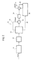
In this connection, the diagram of Figure 1
illustrates, in the form of a block diagram, the
typical structure of a video MPEG encoder.
The system, designated as a whole by 10, comprises,
in the first place, a module 11 designed to carry out
filtering of the chrominance (chroma) component of the
video signal passing from the format 4:2:2 to the
format 4:2:0. Basically, the module 11 contains a
lowpass filter which operates on the chrominance
component, replacing each pixel with a weighted sum of
the surrounding pixels that are set on the same column
multiplied by appropriate coefficients. This enables
the subsequent sub-sampling by two to obtain a halved
vertical definition of the chrominance.
The reference number 12 designates a frame-ordering
module made up of one or more frame memories. The
module 12 is designed to supply at output the frames in
the encoding order required by the syntax of the MPEG
standard.
For example, if the input sequence is IBBPBBP, etc.,
the order at output will be IPBBPBB ...
As has already been explained, I (Intra-Coded
Picture) is a frame and/or a half-frame containing
temporal redundancy; P (Predicted Picture) is a frame
and/or a half-frame the temporal redundancy of which
with respect to a preceding image I or P (which has
been previously encoded/decoded) has been removed; by B
(Bidirectionally Predicted Picture) a frame and/or
half-frame is indicated the temporal redundancy of
which with respect to the preceding image I and the
subsequent image P (or else, the preceding image P and
the subsequent image P, or again, the preceding image P
and the subsequent image I) has been removed. In both
cases, the images I and P are to be considered already
encoded/decoded.
The reference number 13 designates the module for
estimating motion, i.e., the block that is able to
remove the temporal redundancy of the images P and B.
It is to be recalled that the above block works only
on the most energetic component (and hence one that is
rich in information) of the images that make up the
sequence to be encoded, such as the luminance sequence.
One of the important concepts for carrying out
encoding is the estimation of the motion, and the MPEG
standard is based upon the considerations specified
below.
A set of pixels of an image frame may be set in a
position of the subsequent image obtained by
translation of the image in the previous frame.
Suppose, for example, that this set of pixels is a
square of 16x16 pixels. This set of data, together with
the colour information associated to it, is usually
referred to as "macroblock".
Of course, the changes in position of the objects may
expose to the filming camera parts that were previously
not seen, as well as modifications in the shapes of the
objects themselves (for example, as a result of a
zooming function, etc.).
The family of algorithms that are able to identify
and associate the said portions of images is referred
to as "estimation of motion". This association makes it
possible to calculate the portion of difference image,
thus removing the redundant temporal information and
rendering the subsequent process of compression by
means of a DCT, quantization and entropic encoding more
effective.
The reference number 14 designates a module or block
that implements, on the signal coming from an adder
node 23 (which will be explained in greater detail
later), the DCT according to the MPEG standard. The
image I and the images P and B, considered as error
images, are divided into 8x8 blocks Y, U, V, on which
DCT transformation is applied.
The reference number 15 designates a quantizer
module. Here the 8x8 block resulting from DCT
transformation is divided by a matrix, referred to as
"quantization matrix", such as to reduce, more or less
drastically, the dimension in number of bits of the DCT
coefficients. In this case, the tendency is to remove
the information associated to the higher frequencies
which are less visible to the human eye. The result is
re-ordered and sent to the subsequent block, designated
by 16, which implements the run-length coding (RLC) and
the variable-length coding (VLC).
In particular, RLC aims at taking into account the
fact that the code words at output from the quantizer
module 15 tend to contain zero coefficients in a more
or less high number, followed by non-zero values. The
zero values which precede the first non-zero value are
counted, and this count constitutes the first portion
of a word, the second portion of which is the non-zero
coefficient. This method of packeting data is defined
as "run-length coding".
The result thus obtained undergoes variable-length
coding (VLC), also known as Huffman coding.
This type of coding takes into account the fact that
some pairs of values tend to assume more likely values
than others. The more likely values are coded with very
short words (2/3/4 bits), whereas the less likely
values are coded with longer words. Statistically, the
number of bits produced at output is smaller than the
number of bits at input, or rather the number of bits
that there would be if the said coding were not carried
out.
In order to be able to construct the final syntax
envisaged by the MPEG standard, the data generated by
the variable-length encoder (output from the module
16), the quantization matrices, the vectors of motion
(output from the module 13), and other syntactic
elements are sent to an assembler module, designated as
a whole by 17 and comprising a multiplexer 17a and a
buffer 17b.
The limit size of the buffer is specified by the
standard itself and cannot be exceeded.
The quantization block 15 presides over respect of
the said limit, rendering more or less drastic the
process of division of the DCT coefficients according
to whether the latter are more or less close to filling
the buffer and according to the energy of the 8x8
source block taken upstream of the process of
estimation of motion and DCT transformation.
The reference numbers 18 and 19 designate two modules
that basically implement a feedback loop to the
estimation-of-motion function represented by the module
13.
In particular, the module designated by 18 performs
on the data undergoing quantization in the module 15 an
inverse-quantization function.
The signals thus obtained undergo inverse DCT (IDCT)
in the module 19. In practice, the DCT function is
inverted and applied to the 8x8 block at output from
the process of inverse quantization. The function
performed in the module 19 enables passage from the
domain of spatial frequencies to the pixel domain,
obtaining at output:
- the decoded frame (half-frame) I that is
to be stored in an appropriate frame
memory for subsequent removal of temporal
redundancy, with respect thereto, from
the subsequent images P and B; and
- the decoded prediction error frame (half-frame)
P and B which is added to the
information previously removed during the
step of estimation of motion; in the P
case, this resulting sum, stored in an
appropriate frame memory, is used during
the process of estimation of motion for
the subsequent images P and B.
The above is performed in the module designated, as a
whole, by 20, where the frame memories are usually
distinct from the re-ordering memories.
The reference number 21 designates the rate-control
module which interacts for this purpose with the output
of the module 14 and the output of the buffer 17b,
supplying a corresponding control signal mQuant to the
module 15.
Finally, the reference numbers 22 and 23 designate
two adder nodes in which the following are respectively
added:
- the output of the IDCT module 19 and the
output, designated by 24, on which the
data relating to the motion vectors are
transferred from the module 20 to the
estimation-of-motion module 13; and
- the output of the re-ordering module 12
and the output of the module 20, and this
in view of supply to the module 14 which
implements the DCT function.
The foregoing obviously corresponds to altogether
current know-how for persons skilled in the sector, a
know-how which is here recalled merely for purposes of
reference.
The same also applies to the structure of an MPEG
decoder as represented in Figure 2.
In the above-mentioned figure it is possible to note
that the said demodulator, designated as a whole by 30,
in the first place carries out, in a module designated
by 31, detection of the so-called "headers" in the
framework of the MPEG-encoded bitstream and the
subsequent accumulation of the data received within a
buffer 32 designed to absorb any discontinuities in the
said stream.
The module 33 is responsible for performing the
functions of demultiplexing, inverse VLC decoding, and
inverse decoding of the run-level pairs in view of
forwarding of the data thus obtained to a module 34.
Here, under the control of the signal mQuant supplied
by the module 33 itself on a line 35, the inverse-quantization
function is performed.
The signal thus obtained is then passed onto to a
module 36 which performs the inverse DCT function, the
aim being to proceed, in an adder node 37 to
reconstruction of the output signal according to the
signal generated by the motocompensation node 38 which
receives, from the module 33, the data regarding the
motion vectors on a line 39. In the node 37 also the
prediction error is calculated for decoding the
subsequent images P and B (line 40).
It may therefore be stated that the processes
illustrated in Figures 1 and 2 are two concurrent
processes cascaded together.
In the actual use of the MPEG standard it is
therefore possible to transmit (or record) films, or,
in general, video sequences on a variety of channels
and media, each of which has its own characteristics of
capacity, speed and cost.
For example, the distribution of a film starting from
the master recording may take place on a DVD medium,
via satellite, via radio antenna, or via cable.
The band available for transmission may therefore be
different from the one envisaged in the step of
decoding of the video sequence according to the MPEG
standard; or else the bitrate obtained during the step
of encoding of the video sequences may be in excess as
compared to the bitrate allowed by the transmission
channel/recording medium.
Consider, for example, encoding a 6-Mbit/s sequence
according to the MPEG 2 standard.
If the attempt were made to use a 384-kbit/s UMTS
(third-generation cellphone transmission standard)
channel, it would be possible to consider decoding the
sequence, returning to the pixel domain, and then re-encode
the 384-kbit/s sequence afterwards.
In the case where re-encoding was applied to images
having the same spatial resolution as the decoded ones,
the quality of the bitstream obtained would be very
poor in terms of signal-to-noise ratio.
In addition, the decoder located in the receiving
terminal should be able to decode bitstreams in
compliance with an MPEG specification containing a
different spatial resolution from the one with which
the bitstream generated by the first video encoder
would comply.
With regard to the MPEG 2 standard and/or the MPEG 4
standard, there thus emerges the problem of dynamic re-adaptation
of the resolution of the compressed images
into a bitstream encoded in compliance with an MPEG
standard.
In order to achieve the above target, it is possible
to envisage a procedure according to which the MPEG
bitstream is simply decoded, and then the horizontal
resolution and vertical resolution are changed by
operating in the pixel domain. This could be done, for
example, passing from a horizontal and vertical
resolution Hor x Vert to a final resolution
(Hor/N)x(Vert/M), where N and M are positive fractional
integers, then to proceed to the subsequent signal re-encoding
which undergoes change of resolution by means
of an MPEG encoder.
For example, proceeding as described above, it is
possible to have the following cases of change of
resolution:
| INITIAL SPATIAL RESOLUTION | FINAL SPATIAL RESOLUTION |
| HDTV (1920x1088 | SDTV_1 (960x544 or 960x576) |
| or 1920x1152) | → |
| HDTV (1920x1088 | N=M=2 |
| or 1920x1152) | SDTV_2 (720x480 or 720x576) |
| CIF (352x240 or 352x288) | → |
| SDTV_2 | N=2.67 M=2.267 or M=2 |
| SDTV | QCIF → N=M=2 |
| | CIF → N=M=2 |
| | HALF SDTV → N=2 M=1 |
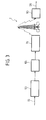
The above solution is in actual fact very complex
from a computational point of view, as may be easily
understood if reference is made to the diagram of
Figure 3, which is a schematic illustration of a
solution based, precisely, on the criterion of
obtaining the change of resolution by operating in the
pixel domain.
If we assume that we are operating on an input
bitstream IS encoded according to the MPEG 2 or MPEG 4
standard, the reference number 50 designates a decoder
that performs a transformation of the MPEG bitstream
(whether it be the specification 2 or the specification
4 is in itself irrelevant) into decoded images ID with
a number of pixels per image equal to Hor x Vert.
The reference number 60 designates a filtering module
with downsampling which performs change of resolution
bringing said resolution to the value (Hor/N)x(Vert/M).
The said module may be, for example, a module able to
perform change of resolution on the basis of a classic
technique that uses finite-impulse-response (FIR)
filters.
The FIR filter in question performs a transformation
based upon the availability of a certain number N of
pixels for each component of luminance and chrominance
of the image. These pixels are multiplied by
appropriate weights, and the results are accumulated
and divided by the sum of said weights. Finally, some
of the pixels are not transmitted in the resulting
image, depending upon the mutation factor of the chosen
resolution.
Starting from an encoded bitstream with arbitrary
bitrate B1, it is always possible to obtain an encoded
bitstream with bitrate B2 by simply connecting the
output of the decoder 50 to the input of the change-of-resolution
block 60. The output from the latter is then
connected to the input of the encoder 70 programmed to
encode at an Mbit/s bitrate B2.
The signal that has undergone change of resolution in
the module 60 is then fed to an MPEG encoder 70 which
is able to generate a syntax in conformance with the
MPEG 2 standard or MPEG 4 standard in view of the
transmission schematically represented in T.
Finally, downstream of transmission (it is to be
recalled that, for the purposes of the present
invention, here the term "transmission" also includes
recording on a physical medium, such as a DVD) the MPEG
(re)encoded signal is fed to a decoder 90 which is able
to read and decode the bitstream received according to
a syntax in conformance with the MPEG standard (either
MPEG 2 or MPEG 4) and with a resolution
(Hor/N)x(Vert/M), in view of the generation of an
output video sequence OS.
If the block diagrams of Figures 1 and 2 are borne in
mind, it will be immediately realized that the sequence
of processes illustrated in Figure 3 presents a
decidedly high computational complexity.
The transcoding operation represented in the diagram
of Figure 3 entails, in fact, as far as the decoder 50
is concerned, the execution of the following steps:
- inverse Huffman coding;
- inverse Run-Length coding;
- inverse quantization;
- inverse discrete cosine transform;
- motocompensation;
- filtering; and
- change of resolution (where envisaged).
For the encoder 70, the following operations become
necessary:
- pre-processing;
- estimation of motion;
- calculation of prediction error;
- cosine transform;
- quantization;
- run-length coding;
- Huffman coding;
- inverse quantization;
- inverse discrete cosine transform; and
- motocompensation.
Finally, for the receiving decoder, the following
operations must be carried out:
- inverse Huffman coding;
- inverse run-length coding;
- inverse quantization;
- inverse discrete cosine transform; and
- motocompensation.
The computational cost lies almost entirely in the
estimation of motion, followed by the direct and
inverse cosine transforms and motocompensation.
Quantization and the (direct and inverse) run-length
and Huffman codings constitute, instead, a contribution
smaller than the previous ones to the overall cost.
The quality of the resulting output bitstream OS
derives, instead, from the information content of the
quantized coefficients. This depends upon the
implementation of the encoder (the decoder is uniquely
defined by ISO/IEC 13818-2 Directives for the MPEG 2
standard and by ISO/IEC 14496-2 Directives for the
MPEG 4 standard), upon the effectiveness of its
estimator of motion, and upon the quality and precision
of the rate control.
A solution on the whole similar to the one described
above with reference to Figure 3 is illustrated in US-A-6
005 621. In particular, this document describes a
method for explicit transcoding which envisages
complete decoding of an input bitstream, scaling of the
images, and subsequent encoding of a number of output
bitstreams with different resolutions by means of a
technique of hierarchical estimation of motion in the
spatial domain.
Object and summary of the present invention
The object of the present invention is thus to
provide a solution that is capable of enabling change
of resolution of an MPEG bitstream without having to
resort to the extremely burdensome solution illustrated
previously.
According to the present invention, the above purpose
is achieved thanks to a process having the
characteristics specifically called for in the ensuing
claims.
The invention also regards the corresponding system
(which can be implemented, for example, in the form of
a dedicated processor, such as a DSP), as well as the
corresponding computer program product, namely, the set
of program codes which may be loaded in the memory of a
digital processor, in particular of the general-purpose
type, and which may enable the processor in question to
carry out the process according to the invention.
Basically, the solution according to the invention
envisages the merging of a decoder with an encoder in
an ensemble designed specifically for variation or else
conservation of the bitrate of a bitstream.
The solution according to the invention enables
reduction in computational complexity and an
improvement or conservation of the quality of the
output signal with respect to the input signal.
The solution according to the invention makes it
possible to achieve dynamic re-adaptation of the
resolution of compressed images in a bitstream encoded
according to the MPEG standard with a high-quality
result and with the possibility of using system
architectures that are optimized in terms of storage
capacity thanks to recourse to structures based upon
multipliers that implement the inverse-quantization
function and the filters. This applies in particular to
the possibility of using the multiplying structure
designed to implement inverse quantization also for the
filtering required by the range of resolution.
The solution according to the invention basically
performs filtering in the domain of the discrete cosine
transform (DCT) instead of in the pixel domain. This is
perfectly legitimate in so far as DC transformation and
the convolution operation (which lies at the basis of
filtering) are linear operations, and hence
interchangeable in order of execution. The fact that
filtering is performed in the DCT domain implies the
availability of the decompressed image in said domain,
hence the availability of the motocompensation
operation in compliance with the MPEG specification.
The solution according to the invention therefore
provides a method alternative to "explicit" decoding
and re-encoding of the type described previously with
reference to Figure 3.
The solution according to the invention operates
directly in the DCT-encoded domain, at a considerably
lower computational cost, at the same time enabling not
only regeneration of a bitstream containing a reduced-resolution
image, but also the possible viewing of the
images on which change of resolution is taking place,
precisely at the moment at which the said change is
occurring. This option enables the user to examine the
quality obtained instant by instant, in order to
intervene, if need be, on said quality.
The solution according to the invention thus presents
two main strong points:
- it avoids the need, when changing resolution, to
(re)estimate the motion; the solution according to the
invention in fact re-uses information of the input
bitstream to generate the output bitstream; and
- it avoids the need, when changing resolution, to
cascade a DCT function and its inverse function IDCT,
since the solution according to the invention operates
entirely in the frequency domain.
In the solution according to the invention, the
portions of bitstream that do not significantly affect
reduction of the bitrate are not processed, but simply
translated according to the syntax and resolution of
the target standard. The motion vectors are
appropriately filtered by means of a transformation
based upon the availability of a certain number M of
motion vectors associated to the macroblocks which are
to be merged into the new macroblock, or else surround
those that are to be merged into the new macroblock.
The motion vectors are multiplied by appropriate
weights, and the results are accumulated and divided by
the sum of the weights. In fact, the motion field must
be appropriately scaled to be associated to the pixel
macroblocks that characterize the target resolution.
The portions of the bitstream that significantly
affect the reduction in bitrate are basically the DCT
coefficients. In particular, the DCT coefficients
undergo the following processing operations:
- inverse variable-length coding (VLC);
- inverse quantization (Q); and
- motocompensation and storage.
Brief description of the annexed drawings
The invention will now be described, purely by way of
non-limiting example, with reference to the attached
drawings, in which:
- Figures 1 to 3, which regard the prior art, have
already been extensively described previously;
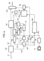
- Figure 4 illustrates, in the form of a block
diagram, the embodiment of the solution according to
the invention; and
- Figure 5 (divided into three parts designated by a,
b and c) and Figure 6 illustrate the embodiment of the
solution according to the invention in greater detail.
Basically, the purpose pursued by the solution
illustrated in Figure 4 is to start from an input
bitstream IS (whether MPEG 2 or MPEG 4) and to
generate, starting therefrom, an output bitstream OS
(again, either MPEG 2 or MPEG 4, according to the
requirements), with the possibility of effecting, in
addition to the change of resolution, also a change of
syntax and/or bitrate.
It will, on the other hand, be appreciated that it is
by no means imperative to make all three of the above
changes simultaneously. Consequently, even though with
reference to Figure 4 a solution will be described that
is able to perform all three changes in question, the
solution according to the invention is suitable for
being applied in contexts in which the only change made
is the change of resolution.
The input bitstream IS is fed from a sorting module
100, which performs a function of parsing of the
headers. This function basically aims at distinguishing
the portions of the bitstream that are not useful for
the purposes of reducing the resolution from the
portions which, instead, are useful for this purpose
(basically, the DCT coefficients).
The former portions of bitstream are sent, through a
line 102, to a module 104 which carries out the
function of change of resolution and syntax by
accessing the syntax fields which store the aforesaid
values and by changing their binary coding into the
values corresponding to the target resolution and
bitrate.
The latter portions of the bitstream (the ones useful
for the purpose of reducing the resolution) are,
instead, sent along a line 106 to a block 108 which
basically carries out the inverse VLC transform.
In particular, the motion vectors that derive from
this operation are sent back, on a line 110, to a block
112, which monitors the function of reshaping of the
motion vectors. This is basically a transformation
based upon the availability of a certain number M of
motion vectors associated to the macroblocks that are
to be merged into the new macroblock or surround those
that are to be merged into the new macroblock. The
motion field must be appropriately scaled to enable the
association of pixels that characterize the target
resolution to the macroblocks.
Downstream of the module 108, there is also
performed, in a module 114, the inverse-quantization
function (IQ).
At output from the module 114 it is possible to
obtain:
- the decoded frame (half-frame) I, in the DCT
domain, which is to be stored in a frame memory so that
it can then contribute to restoring temporal redundancy
to subsequent images P and B according to the
motocompensation process described in the MPEG
standard; and
- the decoded prediction error frame (half-frame) P
and B, in the DCT domain, which is to be added to the
information previously removed during the step of
estimation of motion; in the P case, this resulting
sum, with respect to the preceding I or P, is stored in
an appropriate frame memory and is then used during the
process of compensation of motion for the subsequent
images P and B.
More precisely, storage takes place in a memory block
116 having the function of a frame buffer connected at
input both to the output of the module 112 and to the
output of a module 118 which performs (according to
criteria which will be better described in what
follows) the function of a horizontal and vertical
downsampling filter. The output of the buffer 116
constitutes the input of a further module 120 designed
to perform a horizontal and vertical upsampling
filtering function, which is complementary to the
function performed by the filter 118.
Both the filter 118 and the filter 120 operate
according to filtering matrices applied on the
respective inputs designated by FM.
The output of the module 120 (which in practice
constitutes the prediction signal of the
motocompensation process) is sent to a corresponding
motocompensation module 122, which also receives the
signal at output from the module 114.
The output signal of the module 122 constitutes,
precisely, the input of the filter 118.
More specifically, the inverse oversampling function
represented by the filter 120 is supplied by the blocks
read by the frame memory 116 and is addressed by the
vectors obtained at output from the block 112. The data
thus oversampled are sent to the motocompensation unit
represented by the block 122.
It will be appreciated that the motocompensated
images obtained according to the aforesaid criterion
have the same resolution Hor x Vert as the input
signal. They are not, however, stored in the module 116
with this resolution, but rather with the resolution
obtained downstream of the block 118 that performs
horizontal and vertical filtering in the DCT domain.
The latter resolution is precisely the one resulting
from the downsampling function, namely
(Hor/N)x(Vert/M), with corresponding dimensions in the
storage module 116. In particular, this storage module
may have dimensions [(Hor/N)x(Vert/M)x1.5x1.5x2] for
storing two frames with a precision of 12 bits per
coefficient in the DCT domain and in format 420, which
are useful for the motocompensation process.
The signal subjected to reduction in resolution at
output from the filter 118 can be sent, along a line
118a, to a module 119 which carries out the inverse DCT
(IDCT) function, in such a way as to render visible,
for example on a monitor M, the images on which change
of resolution is taking place. This can be done exactly
at the moment when the change is occurring: the user of
the system can thus inspect the quality obtained
instant by instant so as to be able to intervene, if
need be, on the process of change of resolution,
basically via the matrices FM.
The reference number 126 designates, instead, a
further line on which the results deriving from the
inverse VLC coding operation are sent to a module 128,
which basically superintends a redefinition of the
macroblock parameters according to the modalities
described in greater detail in what follows.
The aim of the foregoing is to arrive, in the module
designated as a whole by 130, at an action of reshaping
of the macroblocks, which, after a prior new VLC
coding, performed in the module designated by 132, are
sent back to an output node 134 in which the portions
of bitstream originally switched on the line 102 and on
the line 106 are again recombined together so as to
generate the output bitstream OS.
In particular, the block 130 operates on the basis of
the signal generated by the module 112 which
superintends reshaping of the motion vectors. The
foregoing is done according to the signal coming from a
module 131, which performs the function of requantization
of the modified-resolution signal received
on a line 118a from the filter 118.
It will be noted that the inverse VLC decoding
operation performed in the module 108 and the (new) VLC
coding operation performed in the module 132 are in
fact linked together to take into account the MPEG 2
and MPEG 4 standards involved (respectively at input
and at output). The aforesaid modules receive at input
also the weighting matrices, which may possibly be
defined by the user and introduced into the system on a
line 136 and used by a module 138.
In order to make the change of resolution, the
solution according to the invention then proceeds to a
filtering in the DCT domain. This takes place according
to the modalities illustrated in greater detail in
Figures 5 and 6.
Of course it is to be recalled that, as has already
been said previously, the functional-block
representation provided by Figure 5 corresponds to
processing operations that may be carried out using
both dedicated processors and general-purpose
processors that are adequately programmed (in a way of
itself known, once the functional specifications that
it is intended to adopt are known).
The part a) of Figure 5 shows, for example, how from
four luminance macroblocks (each consisting of 16x16
pixels) designated by Y1 to Y4 just one is extracted,
designated by Y, in the case of a subsampling factor
equal to 2.
The parts of Figure 5 designated by b) and c) show,
instead, that, for the' chrominance component,
respectively U and V 4:2:0 it is necessary to have
available four 8x8 blocks designated by U1 to U4 and V1
to V4 to merge them into a single block, designated by
U or V, by means of filtering.
The filtering operation is then based upon steps
illustrated in Figure 6.
In particular, if a certain number of 8x8 MPEG blocks
arranged on one and the same horizontal line of a local
buffer are designated by MB1 to MB4, these are made
available in a number of at least three to the
horizontal filter 1181 comprised in the module 118 in
Figure 4. This implements the multiplication of the
above-mentioned macroblocks by an appropriate number of
matrices of size H x V, thus obtaining a new set with
halved horizontal definition.
The blocks thus generated are stored and arranged on
the same vertical line of a second local buffer so as
to make at least three of them available to the
vertical filter 1182 comprised in the module 118 in
Figure 4. This multiplies the macroblocks by an
appropriate number of matrices having size H x V, thus
obtaining a new set with halved vertical definition.
In this way, the equivalent macroblock (shown in the
right-hand part of Figure 5) can be sent to the module
116, to the module 119 that implements the inverse
cosine transform for complete decoding of the images
(in this way making the images simultaneously available
to the transcoded bitstream), and to the module 131,
which, when it receives the macroblock filtered by the
module 118, re-quantizes it according the to
quantization parameter obtained at output from the
block 128. The result is then sent to the block 130.
The block 130 receives the data from the block 112,
the module 131, and the module 128 so as to generate
the new macroblock, which is sent to the module 132.
The data thus obtained are multiplexed in 134 with the
data coming from the module 104.
In 128, the values of the parameters
quantizer_scale_code and quantizer_scale_type are
redefined.
As far as the former parameter is concerned, the
following alternatives are possible:
- re-using the one present in the input bitstream IS;
and
- calculating the weighted mean value for appropriate
coefficients, the minimum value, the median value, or
else the maximum value of N quantizer_scale_code values
associated to the macroblocks present in the input
bitstream, the said macroblocks being the ones that
supply the block 118.
It will be appreciated that the main advantage of the
solution according to the present invention derives, in
terms of computational gain, from the elimination of
the motocompensation, estimate of motion, and inverse
and direct cosine transform blocks.
Of course, without prejudice to the principle of the
invention, the details of implementation and the
embodiments may vary widely with respect to what is
described and illustrated herein, without thereby
departing from the scope of the present invention as
defined in the annexed claims.