EP1231480B1 - Method and device for aligning radar mount direction, and radar aligned by the method or device - Google Patents
Method and device for aligning radar mount direction, and radar aligned by the method or device Download PDFInfo
- Publication number
- EP1231480B1 EP1231480B1 EP02250856A EP02250856A EP1231480B1 EP 1231480 B1 EP1231480 B1 EP 1231480B1 EP 02250856 A EP02250856 A EP 02250856A EP 02250856 A EP02250856 A EP 02250856A EP 1231480 B1 EP1231480 B1 EP 1231480B1
- Authority
- EP
- European Patent Office
- Prior art keywords
- radar
- signal
- antenna
- transmission line
- attenuator
- Prior art date
- Legal status (The legal status is an assumption and is not a legal conclusion. Google has not performed a legal analysis and makes no representation as to the accuracy of the status listed.)
- Expired - Lifetime
Links
Images


Classifications
-
- G—PHYSICS
- G01—MEASURING; TESTING
- G01S—RADIO DIRECTION-FINDING; RADIO NAVIGATION; DETERMINING DISTANCE OR VELOCITY BY USE OF RADIO WAVES; LOCATING OR PRESENCE-DETECTING BY USE OF THE REFLECTION OR RERADIATION OF RADIO WAVES; ANALOGOUS ARRANGEMENTS USING OTHER WAVES
- G01S13/00—Systems using the reflection or reradiation of radio waves, e.g. radar systems; Analogous systems using reflection or reradiation of waves whose nature or wavelength is irrelevant or unspecified
- G01S13/02—Systems using reflection of radio waves, e.g. primary radar systems; Analogous systems
-
- G—PHYSICS
- G01—MEASURING; TESTING
- G01S—RADIO DIRECTION-FINDING; RADIO NAVIGATION; DETERMINING DISTANCE OR VELOCITY BY USE OF RADIO WAVES; LOCATING OR PRESENCE-DETECTING BY USE OF THE REFLECTION OR RERADIATION OF RADIO WAVES; ANALOGOUS ARRANGEMENTS USING OTHER WAVES
- G01S7/00—Details of systems according to groups G01S13/00, G01S15/00, G01S17/00
- G01S7/02—Details of systems according to groups G01S13/00, G01S15/00, G01S17/00 of systems according to group G01S13/00
- G01S7/40—Means for monitoring or calibrating
- G01S7/4052—Means for monitoring or calibrating by simulation of echoes
-
- G—PHYSICS
- G01—MEASURING; TESTING
- G01S—RADIO DIRECTION-FINDING; RADIO NAVIGATION; DETERMINING DISTANCE OR VELOCITY BY USE OF RADIO WAVES; LOCATING OR PRESENCE-DETECTING BY USE OF THE REFLECTION OR RERADIATION OF RADIO WAVES; ANALOGOUS ARRANGEMENTS USING OTHER WAVES
- G01S13/00—Systems using the reflection or reradiation of radio waves, e.g. radar systems; Analogous systems using reflection or reradiation of waves whose nature or wavelength is irrelevant or unspecified
- G01S13/88—Radar or analogous systems specially adapted for specific applications
- G01S13/93—Radar or analogous systems specially adapted for specific applications for anti-collision purposes
- G01S13/931—Radar or analogous systems specially adapted for specific applications for anti-collision purposes of land vehicles
-
- G—PHYSICS
- G01—MEASURING; TESTING
- G01S—RADIO DIRECTION-FINDING; RADIO NAVIGATION; DETERMINING DISTANCE OR VELOCITY BY USE OF RADIO WAVES; LOCATING OR PRESENCE-DETECTING BY USE OF THE REFLECTION OR RERADIATION OF RADIO WAVES; ANALOGOUS ARRANGEMENTS USING OTHER WAVES
- G01S7/00—Details of systems according to groups G01S13/00, G01S15/00, G01S17/00
- G01S7/02—Details of systems according to groups G01S13/00, G01S15/00, G01S17/00 of systems according to group G01S13/00
- G01S7/40—Means for monitoring or calibrating
- G01S7/4004—Means for monitoring or calibrating of parts of a radar system
- G01S7/4026—Antenna boresight
- G01S7/4034—Antenna boresight in elevation, i.e. in the vertical plane
-
- G—PHYSICS
- G01—MEASURING; TESTING
- G01S—RADIO DIRECTION-FINDING; RADIO NAVIGATION; DETERMINING DISTANCE OR VELOCITY BY USE OF RADIO WAVES; LOCATING OR PRESENCE-DETECTING BY USE OF THE REFLECTION OR RERADIATION OF RADIO WAVES; ANALOGOUS ARRANGEMENTS USING OTHER WAVES
- G01S7/00—Details of systems according to groups G01S13/00, G01S15/00, G01S17/00
- G01S7/02—Details of systems according to groups G01S13/00, G01S15/00, G01S17/00 of systems according to group G01S13/00
- G01S7/40—Means for monitoring or calibrating
- G01S7/4052—Means for monitoring or calibrating by simulation of echoes
- G01S7/4082—Means for monitoring or calibrating by simulation of echoes using externally generated reference signals, e.g. via remote reflector or transponder
- G01S7/4086—Means for monitoring or calibrating by simulation of echoes using externally generated reference signals, e.g. via remote reflector or transponder in a calibrating environment, e.g. anechoic chamber
-
- A—HUMAN NECESSITIES
- A61—MEDICAL OR VETERINARY SCIENCE; HYGIENE
- A61B—DIAGNOSIS; SURGERY; IDENTIFICATION
- A61B18/00—Surgical instruments, devices or methods for transferring non-mechanical forms of energy to or from the body
- A61B18/18—Surgical instruments, devices or methods for transferring non-mechanical forms of energy to or from the body by applying electromagnetic radiation, e.g. microwaves
- A61B18/20—Surgical instruments, devices or methods for transferring non-mechanical forms of energy to or from the body by applying electromagnetic radiation, e.g. microwaves using laser
- A61B2018/2035—Beam shaping or redirecting; Optical components therefor
- A61B2018/20351—Scanning mechanisms
- A61B2018/20357—Scanning mechanisms by movable optical fibre end
-
- G—PHYSICS
- G01—MEASURING; TESTING
- G01S—RADIO DIRECTION-FINDING; RADIO NAVIGATION; DETERMINING DISTANCE OR VELOCITY BY USE OF RADIO WAVES; LOCATING OR PRESENCE-DETECTING BY USE OF THE REFLECTION OR RERADIATION OF RADIO WAVES; ANALOGOUS ARRANGEMENTS USING OTHER WAVES
- G01S13/00—Systems using the reflection or reradiation of radio waves, e.g. radar systems; Analogous systems using reflection or reradiation of waves whose nature or wavelength is irrelevant or unspecified
- G01S13/88—Radar or analogous systems specially adapted for specific applications
- G01S13/93—Radar or analogous systems specially adapted for specific applications for anti-collision purposes
- G01S13/931—Radar or analogous systems specially adapted for specific applications for anti-collision purposes of land vehicles
- G01S2013/9327—Sensor installation details
- G01S2013/93271—Sensor installation details in the front of the vehicles
-
- G—PHYSICS
- G01—MEASURING; TESTING
- G01S—RADIO DIRECTION-FINDING; RADIO NAVIGATION; DETERMINING DISTANCE OR VELOCITY BY USE OF RADIO WAVES; LOCATING OR PRESENCE-DETECTING BY USE OF THE REFLECTION OR RERADIATION OF RADIO WAVES; ANALOGOUS ARRANGEMENTS USING OTHER WAVES
- G01S7/00—Details of systems according to groups G01S13/00, G01S15/00, G01S17/00
- G01S7/02—Details of systems according to groups G01S13/00, G01S15/00, G01S17/00 of systems according to group G01S13/00
- G01S7/40—Means for monitoring or calibrating
- G01S7/4004—Means for monitoring or calibrating of parts of a radar system
- G01S7/4026—Antenna boresight
- G01S7/403—Antenna boresight in azimuth, i.e. in the horizontal plane
Definitions
- the present invention relates to a method and device for aligning a radar (radio detecting and ranging device) mount direction, and to a radar system. More specifically, the present invention relates to a radar device which enables easy and correct alignment of a radar mount direction and a transmission/receipt direction to be used for aligning the transmit/receive direction of the radar, as well as to a method of aligning a radar mount direction to be used for aligning the transmit/receive direction of the radar.
- An intervehicle distance warning system or adaptive cruise control which employs a radar, has alreadybeen available as a driving support system.
- Some inter-vehicle warning systems determine a distance between vehicles from a time lag from the time a laser pulse is emitted forward until the time of receipt of the pulse having been transmitted from a reflector of a vehicle driving ahead (i.e., a reflection plate provided on a tail lamp of a vehicle). In this way, application of a radar technology and provision of a radar on a vehicle enable realization of a superior driving support system.
- a radar device on a vehicle. For instance, when a radar is mounted on a vehicle as an inter-vehicle distance warning system, a radar device must be mounted so as to be able to capture the vehicle driving ahead without fail.
- the transmit/receive direction of the radar is aligned with an error of 0.8 degrees, the error is equivalent to a distance of 1.4 m in a case where the vehicle is driving ahead at a distance of about 100 m.
- a sensing area of the system may deviate from a traffic lane, thereby failing to capture the vehicle ahead or misidentify a vehicle driving on the opposite lane as a vehicle driving head of oneself.
- US-A-5,164,734 discloses a radar target device and in particular a radar training system which is adapted to simulate moving objects.
- the system includes a radar and a multiplicity of delayed radar targets.
- US-A-6,087,995 discloses an automobile collision avoidance radar antenna alignment system which includes an interferometer.
- GB 2 318 010 A and WO 99/50626 disclose the use of a delay-line-reflector for calibration of a radar system.
- the present invention has been conceived in light of the foregoing problem and aims at providing a radar mount direction alignment device to be used for accurately aligning the transmit/receive direction of a radar device when the radar device is mounted on a vehicle or the like; a radar device which enables accurate alignment of a transmit/receive direction; and a radar mount direction alignment method for accurately aligning the transmit/receive direction of a radar device.
- the present invention effects alignment of the transmit/receive direction of a radar device by means of placing reflection targets at predetermined locations and utilizing signals reflected from the reflection targets.
- An ordinary radar device for example, a radar device of FM-CW mode, involves noise components stemming from the radar itself, or limitations are imposed on the resolving power of a measurement section of the radar. In relation to a radar device of pulse mode, limitations are imposed on pulse width. Hence, the pulse-mode radar encounters difficulty in measuring a target disposed at short range. For these reasons, the related-art alignment method involves a necessity for ensuring a wide alignment space.
- a radar mount direction alignment adjusting device for a radar being mounted on a vehicle and emitting a signal
- the radar mount direction alignment adjusting device comprises a first reflection unit including:
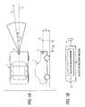
- a method of aligning a radar mount direction according to a comparative example will now be described, by means of taking, as an example, a case where the transmit/receive direction of a radar device 2 mounted on a vehicle 1 is controlled.
- the radar device 2 is mounted on the front of the vehicle 1.
- a transmission section 3 of a radar mount direction alignment device (hereinafter also called simply “alignment device”) is disposed at a position (which is a target used for aligning the mount direction of the radar device 2) spaced distance S 1 (e.g., tens of centimeters to one meter) from the vehicle 1.
- the alignment device has the function of transmitting, toward the radar device 2, a signal which behaves as if having been transmitted from a substance farther from the radar device 2 than a distance S 1 or the function of sending a signal toward the radar device 2 with a predetermined delay time.
- the radar device 2 and the transmission section 3 are situated at a height "h" and aligned with a longitudinal center line Lc of the vehicle 1.
- ⁇ 1 denotes the angle of the transmission section 3 with reference to the center line L 1 of the sensing area of the radar device 2.
- the radar device 2 is equipped with a transmit/receive antenna 4 which rotates within a horizontal plane; and a relative angle sensor 5 for detecting a relative angle with reference to a target (i.e., an azimuth angle).
- Information about the angle ⁇ 1 of the transmission section 3 detected by the relative angle sensor 5 is output to the outside from the radar device 2 and is provided on a display device (not shown).
- the transmit/receive direction of the radar device 2 is aligned such that the angle ⁇ 1 assumes a predetermined value (e.g., 0 degree) while the angle ⁇ 1 is detected by the relative angle sensor 5.
- a predetermined value e.g., 0 degree
- the transmission section 3 is provided on the longitudinal center line Lc of the vehicle 1 and in the position spaced distance S 1 from the vehicle 1.
- the transmit/receive direction of the radar device 2 is aligned such that the angle ⁇ 1 of the transmission section 3 with reference to the radar device 2 detected by the relative angle sensor 5 becomes a predetermined angle.
- the mount direction can be aligned accurately.
- An ordinary radar device for example, a radar device of FM-CW mode, involves noise components stemming from the radar itself, or limitations are imposed on the resolving power of a measurement section of the radar. In relation to a radar device of pulse mode, limitations are imposed on pulse width. Hence, the pulse-mode radar encounters difficulty in measuring a target disposed at short range.
- the alignment device has the function of sending, toward the radar device 2, a signal which behaves as if having been received at and transmitted from an object farther from the radar device 2 than distance S 1 , or the function of sending a signal toward the radar device 2 with a predetermined period of delay time. Hence, an attempt can be made to reduce the space required for alignment.
- an adjustment device having the function of sending, toward the radar device 2, a signal which behaves as if having been received at and transmitted from an object disposed at a position farther from the radar device 2 than a distance of S 1 , or the function of sending a signal toward the radar device 2 with a predetermined period of delay time.
- Figs. 2A and 2B show radar mount direction alignment devices 11 and 21.
- the radar mount direction device 11 comprises an antenna 12 for receiving a signal transmitted from the radar device 2; a transmission line 13 for transmitting a signal; an antenna 14 for transmitting, to the radar device 2, the signal that has been transmitted over the transmission line 13; and directional couplers 15, 16.
- a signal is transmitted from the antenna 14 toward the radar device 2, wherein the signal behaves as if having been received at and transmitted from a position spaced distance S 1 from the radar device 2, plus a distance corresponding to half the distance equivalent to a time delay determined by the length of the transmission line 13.
- the radar mount direction alignment device 21 has a transmit/receive antenna 22; a transmission line 23 for transmitting a signal; and a reflector 24 connected to the transmission line 23.
- a transmit/receive antenna 22 When the signal emitted from the radar device 2 is received by the antenna 22, a signal is transmitted from the antenna 22 toward the radar device 2, wherein the signal behaves as if having been received at and transmitted from a position spaced distance S 1 from the radar device 2, plus a distance corresponding to a time delay determined by the length of the transmission line 13.
- the antenna 12 is provided at the entrance of the transmission line 13, and the antenna 14 is provided at the exit of the same. Further, the antenna 22 is provided at the entrance/exit of the transmission line 23. Alternatively, another member for improving the transmit/receive sensitivity, such as a lens, may be provided in lieu of the antenna.
- the transmission lines 13 and 23 include a waveguide, a dielectric line, and an optical fiber. As shown in Figs. 3A and 3B, there may also be employed a radar mount direction alignment device 11A having an amplifier 17 provided in the transmission line 13, or a radar mount direction alignment device 21A having an amplifier 25 provided in the transmission line 23. Use of these devices enable recovery of a signal level which will drop in the course of the signal passing through the transmission line 13 or 23.
- Fig. 4 shows a side view showing a radar mount direction alignment system 300 according to an embodiment the present invention.
- the radar mount direction alignment system 300 includes a radar 302, a controller 301 for controlling the radar 302, and two reflection units 310 and 320 each disposed in front of the radar 302. Radar wave absorbers 330 are disposed above and below a line connecting the radar 302 and the reflection units 310 and 320.
- the radar 302 as well as the radar device 2 in Fig. 1A, is mounted on a front center of a vehicle.
- the radar 302 transmits a predetermined signal to scan in the horizontal direction of the vehicle.
- the radar 302 scans so that the signal propagates in the vehicle traveling direction parallel to the horizontal direction.
- the signal reflects on a reflector existing in the scanning direction, and is received by the radar 302.
- the controller 301 analyzes the signal received by the radar 302, and determines misalignment of the radar mount direction based on the scanning direction of the signal, the receiving timing and the intensity of the reflected signal from the reflector.
- the reflection unit 310 includes an antenna 313, a transmission line 314, an attenuator 315 and a reflector 316.
- a signal received from the radar 302 by the antenna 313 is reflected by the reflector 316 through the transmission line 314 and the attenuator 315, propagating in the described order.
- the reflected signal propagates through the attenuator 315 and the transmission line 314, and then is transmitted from the antenna 313 to the radar 302.
- the reflection unit 320 includes an antenna 323, a transmission line 324, an attenuator 325 and a reflector 326.
- a signal received from the radar 302 by the antenna 323 is reflected by the reflector 326 through the transmission line 324 and the attenuator 325, propagating in the described order.
- the reflected signal propagates through the attenuator 325 and the transmission line 324, and then is transmitted from the antenna 323 to the radar 302.
- Fig. 5 shows the antennas 313 and 323 as seen from the radar 302 in the signal transmitting direction.
- the antennas 313 and 323 are disposed above and below to have a predetermined space x from the horizontal surface of the signal propagating direction from the radar 302.
- the distances between the radar 302 and the antennas 313 and 323 are the same, and about 1-10m.
- the transmission lines 314 and 324 have different lengths L1 and L2 from each other.
- the lengths of L1 and L2 are about 1-10m. In the fifteenth embodiment, for example, L1 is 5m and L2 is 10m.
- the transmission lines 314 and 324 basically have the same characteristics except for the difference of the length.
- the transmission lines 314 and 324 are made of the same material.
- each of the received signals by the antennas 313 and 314 is attenuated in intensity by a predetermined ratio in accordance with each length L1 or L2.
- the distance x, and the lengths L1 and L2 of the transmission lines 313 and 314 are not limited in the specific values as described above. These values may be set in accordance with the types of radar, or the range or time discrimination ability of the radar 302.
- a transmission line connecting the attenuator 315 with the reflector 316 is the same in the amount of attenuation as a transmission line connecting the attenuator 325 with the reflector 326.
- the attenuators 315 and 325 attenuate the signals transmitted through the transmission lines 314 and 324, by predetermined ratios, respectively.
- the amounts of attenuation by the transmission lines 314 and 324 are set so that the signals outputted from the antennas 313 and 323 to the radar 302 are the same in intensity.
- the amount of attenuation of the signal in the reflection unit 310 is different from the amount of attenuation of the signal in the reflection unit 320 due to the difference between the length L1 (5m) of the transmission line 314 and the length L2 (10m) of the transmission line 324.
- the attenuators 315 and 325 are provided to attenuate each of the signals to compensate for the difference therebetween.
- the attenuators 315 and 325 attenuate the signals so that the input-signal/output-signal intensity ratio of the antenna 313 is the same as the input-signal/output-signal intensity ratio of the antenna 323.
- the attenuation ratio of the reflection unit 310 is the same as that of the reflection unit 320.
- the radio wave absorbers 330 prevent the signal from the radar 302 from being reflected by any members except for the reflection units 310 and 320 and transmitting toward the radar 302. If necessary, additional radio wave absorbers may be provided except for the positions as shown in Fig. 4.
- the scanned signal from the radar 302 directed to the antennas 313 and 323 in the horizontal direction are received by the antennas 313 and 323. Since the distance from the radar 302 to the antenna 313 is the same as that of from the radar 302 to the antenna 323, the received intensities of the signals received by antennas 313 and 323 are the same if the alignment of the radar 302 is proper.
- the signal received by the antenna 313 is transmitted through the transmission line 314 and the attenuator 315, reflected by the reflector 316, and then outputted from the antenna 313 through the transmission line 314 and the attenuator 315.
- the signal received by the antenna 323 is transmitted through the transmission line 324 and the attenuator 325, reflected by the reflector 326, and then outputted from the antenna 323 through the transmission line 324 and the attenuator 325.
- the radar 302 receives the output signals with a timing delay depending on the lengths L1 and L2 of the transmission lines 314 and 315.
- the intensities of the output signals from the reflection units 310 and 320 are the same. Accordingly, the intensities of the received signals from the reflection units 310 and 320 by the radar 302 are the same.
- the alignment of the radar 302 is out of order and the transmitting direction of the signal from the radar 302 is shifted upwardly or downwardly, a difference is generated between the intensities of the signals received by the antenna 313 and antenna 323. Since the reflection units 310 and 320 attenuates the signals by the same ratio, and transmits the attenuated signals toward the radar 302. Accordingly, if the alignment is out of order, the output signals from the antennas 313 and 323 toward the radar 302 are different in intensity, and then the received signals from the reflection units 310 and 320 are also different in intensity.
- Fig. 6 shows a relation between the alignment disorder and intensity difference between the signals received from the reflection units 310 and 320.
- the intensity difference is defined by subtracting the intensity of the output signal from the reflection units 320 from the intensity of the output signal from the reflection units 310.
- the signal intensity of the antenna 313 is stronger than that of the antenna 323. This means that the signal transmitting direction of the radar 302 is shifted upwardly.
- the intensity difference is in the (-)-region, the signal intensity of the antenna 323 is stronger than that of the antenna 313. This means that the signal transmitting direction of the radar 302 is shifted downwardly.
- the mount direction of the radar 302 is adjusted in order to null the intensity difference.
- the alignment of the radar mount direction is properly adjusted in the vertical direction.
- the antennas are positioned above and below with the same distance apart from the radar. Since the transmission lengths in the transmission lines are different in both reflection units, the radar can discriminately receive the each of the output signals from the reflection units. If the ideal distances L1 and L2 of the transmission lines are the same, the radar cannot distinguish the received signals from both reflection units from each other. Namely, if the distances L1 and L2 are the same, the radar cannot determine the received signal having the larger intensity to be transmitted from either of the reflection units even if the radar is disposed in disorder. However, the distances are different, the radar can distinguish the signals from each other since the radar has a function of measuring a distance from the reflection unit and a receiving level that depends on the distance from the reflection unit. To utilize the characteristics, a user can adjust the alignment of the radar mount direction in the vertical direction.
- the attenuator may be provided in either of the reflection units, because the length of the transmission line is different and the attenuation ratio of the reflection unit is the same in both of the reflection units.
Landscapes
- Engineering & Computer Science (AREA)
- Radar, Positioning & Navigation (AREA)
- Remote Sensing (AREA)
- Physics & Mathematics (AREA)
- Computer Networks & Wireless Communication (AREA)
- General Physics & Mathematics (AREA)
- Electromagnetism (AREA)
- Radar Systems Or Details Thereof (AREA)
Description
- The present invention relates to a method and device for aligning a radar (radio detecting and ranging device) mount direction, and to a radar system. More specifically, the present invention relates to a radar device which enables easy and correct alignment of a radar mount direction and a transmission/receipt direction to be used for aligning the transmit/receive direction of the radar, as well as to a method of aligning a radar mount direction to be used for aligning the transmit/receive direction of the radar.
- An intervehicle distance warning system or adaptive cruise control, which employs a radar, has alreadybeen available as a driving support system. Some inter-vehicle warning systems determine a distance between vehicles from a time lag from the time a laser pulse is emitted forward until the time of receipt of the pulse having been transmitted from a reflector of a vehicle driving ahead (i.e., a reflection plate provided on a tail lamp of a vehicle). In this way, application of a radar technology and provision of a radar on a vehicle enable realization of a superior driving support system.
- However, the following problem is encountered in mounting a radar device on a vehicle. For instance, when a radar is mounted on a vehicle as an inter-vehicle distance warning system, a radar device must be mounted so as to be able to capture the vehicle driving ahead without fail.
- If the transmit/receive direction of the radar is aligned with an error of 0.8 degrees, the error is equivalent to a distance of 1.4 m in a case where the vehicle is driving ahead at a distance of about 100 m. Even when another vehicle is driving ahead of a vehicle equipped with an inter-vehicle distance warning system, a sensing area of the system may deviate from a traffic lane, thereby failing to capture the vehicle ahead or misidentify a vehicle driving on the opposite lane as a vehicle driving head of oneself.
- US-A-5,164,734 discloses a radar target device and in particular a radar training system which is adapted to simulate moving objects. The system includes a radar and a multiplicity of delayed radar targets.
- US-A-6,087,995 discloses an automobile collision avoidance radar antenna alignment system which includes an interferometer.
-
GB 2 318 010 A and WO 99/50626 disclose the use of a delay-line-reflector for calibration of a radar system. - The present invention has been conceived in light of the foregoing problem and aims at providing a radar mount direction alignment device to be used for accurately aligning the transmit/receive direction of a radar device when the radar device is mounted on a vehicle or the like; a radar device which enables accurate alignment of a transmit/receive direction; and a radar mount direction alignment method for accurately aligning the transmit/receive direction of a radar device.
- As a radar mount direction alignment method for accurately aligning the transmit/receive direction of a radar device, the present invention effects alignment of the transmit/receive direction of a radar device by means of placing reflection targets at predetermined locations and utilizing signals reflected from the reflection targets.
- An ordinary radar device; for example, a radar device of FM-CW mode, involves noise components stemming from the radar itself, or limitations are imposed on the resolving power of a measurement section of the radar. In relation to a radar device of pulse mode, limitations are imposed on pulse width. Hence, the pulse-mode radar encounters difficulty in measuring a target disposed at short range. For these reasons, the related-art alignment method involves a necessity for ensuring a wide alignment space.
- In accordance with the present invention, a radar mount direction alignment adjusting device for a radar being mounted on a vehicle and emitting a signal, the radar mount direction alignment adjusting device comprises a first reflection unit including:
- a first antenna for receiving the signal from the radar and transmitting the signal toward the radar;
- a first transmission line for transmitting the signal received by the first antenna;
- a first attenuator for attenuating the signal from the first transmission line by a first predetermined ratio; and
- a first reflector for reflecting the signal from the first attenuator; and
- a second reflection unit including:
- a second antenna for receiving the signal from the radar and transmitting the signal toward the radar;
- a second transmission line for transmitting the signal received by the second antenna;
- a second attenuator for attenuating the signal from the second transmission line by a second predetermined ratio; and
- a second reflector for reflecting the signal from the second attenuator,
- An example of an alignment adjusting device and method according to the invention will now be described with reference to the accompanying drawings, in which:-
- Fig. 1A is a descriptive view for describing a method of aligning a radar mount direction according to a first comparative example, and Fig. 1B is a block diagram schematically showing the principal section of a radar device;
- Figs. 2A and 2B are block diagrams schematically showing the principal section of the radar mount direction alignment device according to the comparative example;
- Fig. 4 shows a side view showing a radar mount direction alignment system according to an embodiment of the present invention.
- Fig. 5 shows antennas as seen from a radar in the signal transmitting direction.
- Fig. 6 shows a relation between alignment disorder and intensity difference.
- Embodiments of a device and method of aligning a radar mount direction according to the present invention will be described hereinbelow by reference to the accompanying drawings.
- A method of aligning a radar mount direction according to a comparative example will now be described, by means of taking, as an example, a case where the transmit/receive direction of a
radar device 2 mounted on avehicle 1 is controlled. As shown in Fig. 1A, theradar device 2 is mounted on the front of thevehicle 1. Atransmission section 3 of a radar mount direction alignment device (hereinafter also called simply "alignment device") is disposed at a position (which is a target used for aligning the mount direction of the radar device 2) spaced distance S1 (e.g., tens of centimeters to one meter) from thevehicle 1. - The alignment device has the function of transmitting, toward the
radar device 2, a signal which behaves as if having been transmitted from a substance farther from theradar device 2 than a distance S1 or the function of sending a signal toward theradar device 2 with a predetermined delay time. Theradar device 2 and thetransmission section 3 are situated at a height "h" and aligned with a longitudinal center line Lc of thevehicle 1. In the drawing, θ1 denotes the angle of thetransmission section 3 with reference to the center line L1 of the sensing area of theradar device 2. - As shown in Fig. 1B, the
radar device 2 is equipped with a transmit/receiveantenna 4 which rotates within a horizontal plane; and arelative angle sensor 5 for detecting a relative angle with reference to a target (i.e., an azimuth angle). Information about the angle θ1 of thetransmission section 3 detected by therelative angle sensor 5 is output to the outside from theradar device 2 and is provided on a display device (not shown). - When the mount direction of the
radar device 2 is aligned, the transmit/receive direction of theradar device 2 is aligned such that the angle θ1 assumes a predetermined value (e.g., 0 degree) while the angle θ1 is detected by therelative angle sensor 5. - Under the radar mount direction alignment method according to the first embodiment, the
transmission section 3 is provided on the longitudinal center line Lc of thevehicle 1 and in the position spaced distance S1 from thevehicle 1. The transmit/receive direction of theradar device 2 is aligned such that the angle θ1 of thetransmission section 3 with reference to theradar device 2 detected by therelative angle sensor 5 becomes a predetermined angle. Hence, the mount direction can be aligned accurately. - An ordinary radar device; for example, a radar device of FM-CW mode, involves noise components stemming from the radar itself, or limitations are imposed on the resolving power of a measurement section of the radar. In relation to a radar device of pulse mode, limitations are imposed on pulse width. Hence, the pulse-mode radar encounters difficulty in measuring a target disposed at short range. However, the alignment device has the function of sending, toward the
radar device 2, a signal which behaves as if having been received at and transmitted from an object farther from theradar device 2 than distance S1, or the function of sending a signal toward theradar device 2 with a predetermined period of delay time. Hence, an attempt can be made to reduce the space required for alignment. - Next will be described an adjustment device having the function of sending, toward the
radar device 2, a signal which behaves as if having been received at and transmitted from an object disposed at a position farther from theradar device 2 than a distance of S1, or the function of sending a signal toward theradar device 2 with a predetermined period of delay time. - Figs. 2A and 2B show radar mount
direction alignment devices mount direction device 11 comprises anantenna 12 for receiving a signal transmitted from theradar device 2; atransmission line 13 for transmitting a signal; anantenna 14 for transmitting, to theradar device 2, the signal that has been transmitted over thetransmission line 13; anddirectional couplers radar device 2 is received by theantenna 12, a signal is transmitted from theantenna 14 toward theradar device 2, wherein the signal behaves as if having been received at and transmitted from a position spaced distance S1 from theradar device 2, plus a distance corresponding to half the distance equivalent to a time delay determined by the length of thetransmission line 13. - The radar mount
direction alignment device 21 has a transmit/receiveantenna 22; atransmission line 23 for transmitting a signal; and areflector 24 connected to thetransmission line 23. When the signal emitted from theradar device 2 is received by theantenna 22, a signal is transmitted from theantenna 22 toward theradar device 2, wherein the signal behaves as if having been received at and transmitted from a position spaced distance S1 from theradar device 2, plus a distance corresponding to a time delay determined by the length of thetransmission line 13. - Here, the
antenna 12 is provided at the entrance of thetransmission line 13, and theantenna 14 is provided at the exit of the same. Further, theantenna 22 is provided at the entrance/exit of thetransmission line 23. Alternatively, another member for improving the transmit/receive sensitivity, such as a lens, may be provided in lieu of the antenna. Thetransmission lines direction alignment device 11A having anamplifier 17 provided in thetransmission line 13, or a radar mountdirection alignment device 21A having anamplifier 25 provided in thetransmission line 23. Use of these devices enable recovery of a signal level which will drop in the course of the signal passing through thetransmission line - Fig. 4 shows a side view showing a radar mount
direction alignment system 300 according to an embodiment the present invention. - The radar mount
direction alignment system 300 includes aradar 302, acontroller 301 for controlling theradar 302, and tworeflection units radar 302.Radar wave absorbers 330 are disposed above and below a line connecting theradar 302 and thereflection units - The
radar 302, as well as theradar device 2 in Fig. 1A, is mounted on a front center of a vehicle. Theradar 302 transmits a predetermined signal to scan in the horizontal direction of the vehicle. Theradar 302 scans so that the signal propagates in the vehicle traveling direction parallel to the horizontal direction. The signal reflects on a reflector existing in the scanning direction, and is received by theradar 302. - The
controller 301 analyzes the signal received by theradar 302, and determines misalignment of the radar mount direction based on the scanning direction of the signal, the receiving timing and the intensity of the reflected signal from the reflector. - The
reflection unit 310 includes anantenna 313, atransmission line 314, anattenuator 315 and areflector 316. A signal received from theradar 302 by theantenna 313 is reflected by thereflector 316 through thetransmission line 314 and theattenuator 315, propagating in the described order. The reflected signal propagates through theattenuator 315 and thetransmission line 314, and then is transmitted from theantenna 313 to theradar 302. - The
reflection unit 320, as well as thereflection unit 310, includes anantenna 323, atransmission line 324, anattenuator 325 and areflector 326. A signal received from theradar 302 by theantenna 323 is reflected by thereflector 326 through thetransmission line 324 and theattenuator 325, propagating in the described order. The reflected signal propagates through theattenuator 325 and thetransmission line 324, and then is transmitted from theantenna 323 to theradar 302. - Fig. 5 shows the
antennas radar 302 in the signal transmitting direction. Theantennas radar 302. The distances between theradar 302 and theantennas - The
transmission lines transmission lines transmission lines transmission lines antennas transmission lines radar 302. - A transmission line connecting the
attenuator 315 with thereflector 316 is the same in the amount of attenuation as a transmission line connecting theattenuator 325 with thereflector 326. - The
attenuators transmission lines radar 302 is proper, the amounts of attenuation by thetransmission lines antennas radar 302 are the same in intensity. - Unless the
attenuators reflection unit 310 is different from the amount of attenuation of the signal in thereflection unit 320 due to the difference between the length L1 (5m) of thetransmission line 314 and the length L2 (10m) of thetransmission line 324. Theattenuators antenna 313 is the same in intensity as the signal entering theantenna 323, theattenuators antenna 313 is the same as the input-signal/output-signal intensity ratio of theantenna 323. Namely, the attenuation ratio of thereflection unit 310 is the same as that of thereflection unit 320. - The
radio wave absorbers 330 prevent the signal from theradar 302 from being reflected by any members except for thereflection units radar 302. If necessary, additional radio wave absorbers may be provided except for the positions as shown in Fig. 4. - There will be described a mount direction alignment method of the
radar 302 using the radarmountdirection alignment system 300. - The scanned signal from the
radar 302 directed to theantennas antennas radar 302 to theantenna 313 is the same as that of from theradar 302 to theantenna 323, the received intensities of the signals received byantennas radar 302 is proper. - The signal received by the
antenna 313 is transmitted through thetransmission line 314 and theattenuator 315, reflected by thereflector 316, and then outputted from theantenna 313 through thetransmission line 314 and theattenuator 315. The signal received by theantenna 323 is transmitted through thetransmission line 324 and theattenuator 325, reflected by thereflector 326, and then outputted from theantenna 323 through thetransmission line 324 and theattenuator 325. Theradar 302 receives the output signals with a timing delay depending on the lengths L1 and L2 of thetransmission lines - When the alignment of the
radar 302 is proper, since the signals transmitted through thereflection units reflection units reflection units radar 302 are the same. - On the other hand, when the alignment of the
radar 302 is out of order and the transmitting direction of the signal from theradar 302 is shifted upwardly or downwardly, a difference is generated between the intensities of the signals received by theantenna 313 andantenna 323. Since thereflection units radar 302. Accordingly, if the alignment is out of order, the output signals from theantennas radar 302 are different in intensity, and then the received signals from thereflection units - Fig. 6 shows a relation between the alignment disorder and intensity difference between the signals received from the
reflection units reflection units 320 from the intensity of the output signal from thereflection units 310. - If the intensity difference is in the (+)-region, the signal intensity of the
antenna 313 is stronger than that of theantenna 323. This means that the signal transmitting direction of theradar 302 is shifted upwardly. To the contrary, if the intensity difference is in the (-)-region, the signal intensity of theantenna 323 is stronger than that of theantenna 313. This means that the signal transmitting direction of theradar 302 is shifted downwardly. - To adjust the alignment of the
radar 302 in actual, the mount direction of theradar 302 is adjusted in order to null the intensity difference. Herewith, the alignment of the radar mount direction is properly adjusted in the vertical direction. - According to the example of the present invention, the antennas are positioned above and below with the same distance apart from the radar. Since the transmission lengths in the transmission lines are different in both reflection units, the radar can discriminately receive the each of the output signals from the reflection units. If the ideal distances L1 and L2 of the transmission lines are the same, the radar cannot distinguish the received signals from both reflection units from each other. Namely, if the distances L1 and L2 are the same, the radar cannot determine the received signal having the larger intensity to be transmitted from either of the reflection units even if the radar is disposed in disorder. However, the distances are different, the radar can distinguish the signals from each other since the radar has a function of measuring a distance from the reflection unit and a receiving level that depends on the distance from the reflection unit. To utilize the characteristics, a user can adjust the alignment of the radar mount direction in the vertical direction.
- In the example, although an attenuator is provided in each of the
reflection units
wherein the first predetermined ratio and the second predetermined ratio are set so that when the first antenna and the second antenna receive signals having the same intensity, an intensity of the signal output from the first reflecting unit is equal to an intensity of the signal output from the second reflecting unit.
Claims (6)
- A radar mount direction alignment adjusting device for a radar (302) being mounted on a vehicle and emitting a signal, the radar mount direction alignment adjusting device comprising:a first reflection unit including:wherein the length of the first transmission line (314) is different from the that of the second transmission line (324); anda first antenna (313) for receiving the signal from the radar and transmitting the signal toward the radar;a first transmission line (314) for transmitting the signal received by the first antenna (313);a first attenuator (315) for attenuating the signal from the first transmission line (314) by a first predetermined ratio; anda first reflector (316) for reflecting the signal from the first attenuator; anda second reflection unit including:a second antenna (323) for receiving the signal from the radar and transmitting the signal toward the radar;a second transmission line (324) for transmitting the signal received by the second antenna;a second attenuator (325) for attenuating the signal from the second transmission line by a second predetermined ratio; anda second reflector (326) for reflecting the signal from the second attenuator,
wherein the first predetermined ratio and the second predetermined ratio are set so that when the first antenna (313) and the second antenna (323) receive signals having the same intensity, an intensity of the signal output from the first reflecting unit is equal to an intensity of the signal output from the second reflecting unit. - The radar mount direction alignment adjusting device as claimed in claim 1, wherein the signal reflected by the first reflector (316) is transmitted through the first attenuator (715) and the first transmission line (314) to the first antenna (313) and outputted toward the radar; and
the signal reflected by the second reflector (326) is transmitted through the second attenuator (325) and the second transmission line (324) to the second antenna (323) and outputted toward the radar. - The radar mount direction alignment adjusting device as claimed in claim 1, wherein the first predetermined value of the first attenuator (315) and the second predetermined value of the second attenuator (325) are determined in accordance with the length of the first transmission line (314) and the length of the second transmission line (324).
- The radar mount direction alignment adjusting device as claimed in claim 1, wherein the first antenna (313) of the first reflection unit and the second antenna (323) of the second reflection unit are spaced with a same distance from a horizontal surface including the scanning direction of the radar.
- The radar mount direction alignment adjusting device as claimed in claim 1, wherein the first antenna (313) of the first reflection unit and the second antenna (323) of the second reflection unit are spaced with a same distance from the radar.
- The radar mount direction alignment adjusting device as claimed in claim 2, wherein the mount direction of the radar is adjusted in accordance with the signals received from the first reflection unit and the second reflection unit.
Applications Claiming Priority (6)
| Application Number | Priority Date | Filing Date | Title |
|---|---|---|---|
| JP2001032996A JP3500360B2 (en) | 2001-02-08 | 2001-02-08 | Radar mounting direction adjusting device and radar mounting direction adjusting method |
| JP2001032996 | 2001-02-08 | ||
| JP2001034725A JP2002243838A (en) | 2001-02-09 | 2001-02-09 | Method and device for adjusting radar attaching direction |
| JP2001034406A JP2002243837A (en) | 2001-02-09 | 2001-02-09 | Radar attaching direction adjusting method and radar device |
| JP2001034406 | 2001-02-09 | ||
| JP2001034725 | 2001-02-09 |
Publications (3)
| Publication Number | Publication Date |
|---|---|
| EP1231480A2 EP1231480A2 (en) | 2002-08-14 |
| EP1231480A3 EP1231480A3 (en) | 2003-08-06 |
| EP1231480B1 true EP1231480B1 (en) | 2006-06-21 |
Family
ID=27345944
Family Applications (1)
| Application Number | Title | Priority Date | Filing Date |
|---|---|---|---|
| EP02250856A Expired - Lifetime EP1231480B1 (en) | 2001-02-08 | 2002-02-07 | Method and device for aligning radar mount direction, and radar aligned by the method or device |
Country Status (5)
| Country | Link |
|---|---|
| US (1) | US6933883B2 (en) |
| EP (1) | EP1231480B1 (en) |
| KR (1) | KR100489226B1 (en) |
| CN (1) | CN1293390C (en) |
| DE (1) | DE60212468T2 (en) |
Families Citing this family (55)
| Publication number | Priority date | Publication date | Assignee | Title |
|---|---|---|---|---|
| JP4740449B2 (en) * | 2000-12-27 | 2011-08-03 | 富士通テン株式会社 | Vertical axis deviation detection device for automotive radar |
| DE10229334B4 (en) * | 2002-06-29 | 2010-09-23 | Robert Bosch Gmbh | Method and device for calibrating sensors in motor vehicles by means of a calibration object with triple mirror as a reference feature |
| US7136753B2 (en) * | 2002-12-05 | 2006-11-14 | Denso Corporation | Object recognition apparatus for vehicle, inter-vehicle control apparatus, and distance measurement apparatus |
| US7162200B2 (en) * | 2003-04-15 | 2007-01-09 | Chung Shan Institute Of Science And Technology | Antenna calibration system and method |
| US6731236B1 (en) * | 2003-06-11 | 2004-05-04 | Honeywell International Inc. | Methods and apparatus for optimizing interferometric radar altimeter cross track accuracy |
| JP4232570B2 (en) * | 2003-07-31 | 2009-03-04 | 株式会社デンソー | Radar equipment for vehicles |
| US7382913B2 (en) * | 2003-08-22 | 2008-06-03 | Hunter Engineering Company | Method and apparatus for guiding placement of vehicle service fixtures |
| JP2006184130A (en) * | 2004-12-27 | 2006-07-13 | Tdk Corp | Radar device |
| JP4109679B2 (en) * | 2005-02-07 | 2008-07-02 | 三菱電機株式会社 | Radio wave axis adjustment device for automotive radar |
| US7253722B2 (en) * | 2005-06-09 | 2007-08-07 | Delphi Technologies, Inc. | Sensor alignment detection method for an infrared blind-zone sensing system |
| JP4444265B2 (en) * | 2006-11-27 | 2010-03-31 | 富士通テン株式会社 | Vehicular radar apparatus and method for manufacturing the same, reference section, and adjustment method of beam emitting direction |
| US7884772B2 (en) * | 2007-05-07 | 2011-02-08 | Lockheed Martin Corporation | Radar apparatus and alignment sensor |
| DE602007009523D1 (en) | 2007-08-10 | 2010-11-11 | Siemens Milltronics Proc Instr | Calibration system for time-of-flight radar |
| DE102007041511A1 (en) * | 2007-08-31 | 2009-03-05 | Hella Kgaa Hueck & Co. | Radar sensor adjusting and testing device for use in motor vehicle i.e. car, has tunnel-shaped absorber arranged between radar sensor and reflector such that optical path of radar sensor is surrounded by absorber |
| DE102008054579B4 (en) | 2008-12-12 | 2022-10-13 | Robert Bosch Gmbh | Maladjustment detection for a radar sensor |
| KR101053855B1 (en) * | 2009-01-22 | 2011-08-03 | 주식회사 만도 | Sensor vertical alignment regulator and sensor |
| CN101788659B (en) * | 2009-01-22 | 2013-04-03 | 株式会社万都 | Apparatus and sensor for adjusting sensor vertical alignment |
| JP4790045B2 (en) * | 2009-05-19 | 2011-10-12 | 本田技研工業株式会社 | Device for determining radar axis misalignment |
| CN101702018B (en) * | 2009-11-12 | 2012-01-04 | 中国电子科技集团公司第四十一研究所 | Calibrating method for big modulation bandwidth linear FM signal frequency response |
| DE102010020022A1 (en) * | 2010-05-10 | 2011-11-10 | Valeo Schalter Und Sensoren Gmbh | Driver assistance device for a vehicle, vehicle and method for operating a radar device |
| KR100979943B1 (en) * | 2010-05-26 | 2010-09-06 | 삼성탈레스 주식회사 | Apparatus and method for adjusting angle of vehicle radar antenna |
| JP5697904B2 (en) * | 2010-06-16 | 2015-04-08 | 株式会社豊田中央研究所 | Radar apparatus and detection method |
| US9472097B2 (en) | 2010-11-15 | 2016-10-18 | Image Sensing Systems, Inc. | Roadway sensing systems |
| US8849554B2 (en) | 2010-11-15 | 2014-09-30 | Image Sensing Systems, Inc. | Hybrid traffic system and associated method |
| DE102011079522A1 (en) * | 2011-07-21 | 2013-01-24 | Robert Bosch Gmbh | DETECTION OF DEPRECIATION OF A RADAR SENSOR OF A VEHICLE |
| US8692707B2 (en) | 2011-10-06 | 2014-04-08 | Toyota Motor Engineering & Manufacturing North America, Inc. | Calibration method for automotive radar using phased array |
| DE102012201986A1 (en) * | 2012-02-10 | 2013-08-14 | Robert Bosch Gmbh | Radar sensor device with adjustment mirror |
| KR101335074B1 (en) * | 2012-03-02 | 2013-12-03 | 주식회사 만도 | Alignment system and method of radar apparatus |
| KR102048361B1 (en) * | 2013-02-28 | 2019-11-25 | 엘지전자 주식회사 | Distance detecting device and Image processing apparatus including the same |
| EP2993485A4 (en) | 2013-04-30 | 2017-03-08 | Furukawa Electric Co., Ltd. | Radar apparatus |
| DE102013209494A1 (en) * | 2013-05-22 | 2014-11-27 | Robert Bosch Gmbh | Method and device for determining a misalignment of a radar sensor of a vehicle |
| KR102157993B1 (en) * | 2013-11-28 | 2020-09-21 | 현대모비스 주식회사 | Method and system for alignment radar of vehicle |
| WO2015148830A1 (en) * | 2014-03-28 | 2015-10-01 | Hunter Engineering Company | Calibration fixture for range finding sensors on a vehicle |
| EP3180636B1 (en) * | 2014-08-15 | 2019-05-22 | Robert Bosch GmbH | Method and system for determining misalignment of a radar sensor unit |
| US10890648B2 (en) * | 2014-10-24 | 2021-01-12 | Texas Instruments Incorporated | Method and apparatus for generating alignment matrix for camera-radar system |
| US9568592B1 (en) * | 2014-11-04 | 2017-02-14 | Google Inc. | Automotive sensor alignment with external IMU tool |
| CN105738871A (en) * | 2014-12-24 | 2016-07-06 | 松下知识产权经营株式会社 | Radar system |
| US20160223649A1 (en) * | 2015-01-30 | 2016-08-04 | Robert Bosch Gmbh | Systems and methods for radar vertical misalignment detection |
| US9784829B2 (en) * | 2015-04-06 | 2017-10-10 | GM Global Technology Operations LLC | Wheel detection and its application in object tracking and sensor registration |
| CN104808185B (en) * | 2015-05-04 | 2018-02-09 | 北京敏视达雷达有限公司 | A kind of detection method and device of angular error |
| KR101684551B1 (en) * | 2015-06-26 | 2016-12-08 | 현대자동차 주식회사 | Mounting angle detection system of bsd sensor and the detection method |
| US10527714B2 (en) * | 2016-11-17 | 2020-01-07 | Rohde & Schwarz Gmbh & Co. Kg | Calibration device and calibration method for calibrating antenna arrays |
| CN108614239A (en) * | 2016-12-12 | 2018-10-02 | 北京行易道科技有限公司 | To Barebone |
| DE102017123435A1 (en) | 2017-10-09 | 2019-04-11 | Krohne Messtechnik Gmbh | Apparatus for calibrating a radar range finder and method for calibrating a radar rangefinder |
| DE102018203941A1 (en) * | 2018-03-15 | 2019-09-19 | Robert Bosch Gmbh | Automatic calibration of a vehicle radar sensor |
| US10830872B2 (en) * | 2018-06-07 | 2020-11-10 | Fca Us Llc | Vehicle multi-radar relative phase interferometry alignment systems and methods |
| KR102506943B1 (en) | 2018-06-25 | 2023-03-07 | 현대자동차 주식회사 | System and method for vehicle radar inspection |
| EP3588135B1 (en) * | 2018-06-28 | 2021-05-05 | Aptiv Technologies Limited | Method of determining an alignment error of an antenna and vehicle with an antenna and a detection device |
| JP7096114B2 (en) * | 2018-09-25 | 2022-07-05 | 本田技研工業株式会社 | Sensor axis adjustment device and sensor axis adjustment method |
| WO2020080569A1 (en) * | 2018-10-18 | 2020-04-23 | 인지니어스 주식회사 | Driver drowsiness determination device using radar signal and operation method thereof |
| US11313946B2 (en) * | 2018-11-12 | 2022-04-26 | Hunter Engineering Company | Method and apparatus for identification of calibration targets during vehicle radar system service procedures |
| CN109367529B (en) * | 2018-11-30 | 2024-03-26 | 南京天安汽车电子科技股份有限公司 | Millimeter wave radar combined installation structure and virtual tunnel construction and obstacle judgment method |
| CN109738905B (en) * | 2018-12-28 | 2021-03-23 | 百度在线网络技术(北京)有限公司 | Method, device and equipment for determining installation position of ultrasonic sensor |
| US11069982B2 (en) * | 2019-01-02 | 2021-07-20 | Honda Motor Co., Ltd. | Anechoic chamber and method of calibrating a radar system |
| CN111064477B (en) * | 2019-12-31 | 2020-08-04 | 郑州科技学院 | Electric power communication signal transmitting device with adjustable angle |
Family Cites Families (45)
| Publication number | Priority date | Publication date | Assignee | Title |
|---|---|---|---|---|
| US2505525A (en) * | 1944-07-26 | 1950-04-25 | Philco Corp | Device for testing pulse type radar system |
| US2841785A (en) * | 1946-05-08 | 1958-07-01 | Jr Frederic Cunningham | Target simulating signal generator |
| US2802207A (en) * | 1949-06-21 | 1957-08-06 | Jr Henry S Sommers | Method of adjusting radar tracking apparatus |
| GB691570A (en) * | 1951-03-22 | 1953-05-13 | Vickers Electrical Co Ltd | Improvements relating to radar testing equipment |
| US2922157A (en) * | 1954-03-30 | 1960-01-19 | Pitometer Log Corp | Radar signal simulator |
| US2781511A (en) * | 1955-01-13 | 1957-02-12 | Jr Charles B Pear | Echo simulator |
| US2825058A (en) * | 1955-02-04 | 1958-02-25 | Earl H Rix | Target simulator for radar system checking |
| CH355485A (en) * | 1955-12-12 | 1961-07-15 | Gen Mills Inc | Radar test facility |
| US2942257A (en) * | 1955-12-12 | 1960-06-21 | Gen Mills Inc | Radar tester |
| US3018478A (en) * | 1957-08-05 | 1962-01-23 | Westinghouse Electric Corp | Pulse doppler moving target simulator |
| US2952848A (en) * | 1958-12-24 | 1960-09-13 | Aircraft Armaments Inc | Method and means for testing the calibration of radar systems |
| US3162854A (en) * | 1961-05-08 | 1964-12-22 | Robert R Campbell | Target simulator for pulse doppler radar |
| BE636918A (en) * | 1962-09-04 | |||
| GB1085071A (en) * | 1963-11-15 | 1967-09-27 | Elliott Brothers London Ltd | Radar target simulators |
| US3329953A (en) * | 1966-06-15 | 1967-07-04 | Sierra Research Corp | Doppler target simulator |
| GB2035744B (en) * | 1978-11-22 | 1983-05-05 | Marconi Co Ltd | Apparatus for detecting moving targets or other objects of interest |
| FR2569857B1 (en) * | 1982-10-13 | 1988-05-13 | Trt Telecom Radio Electr | ELECTRICALLY VARIABLE DELAY SIMULATOR FOR FREQUENCY MODULATED CONTINUOUS WAVE DISTANCE MEASUREMENT APPARATUS |
| FR2573217B1 (en) * | 1984-11-13 | 1987-01-23 | Trt Telecom Radio Electr | DELAY SIMULATOR FOR FREQUENCY MODULATED CONTINUOUS WAVE DISTANCE MEASUREMENT APPARATUS |
| US4683473A (en) * | 1986-01-10 | 1987-07-28 | Honeywell Inc. | Radar transit time simulator device |
| US4737792A (en) * | 1986-06-20 | 1988-04-12 | Westinghouse Electric Corp. | Counter-based simulated target generator |
| US5262787A (en) * | 1987-03-06 | 1993-11-16 | Raytheon Company | Recirculating delay line radar performance monitor |
| IL102119A (en) * | 1991-06-05 | 1995-11-27 | Commw Of Australia | Radar environment generator |
| US5164734A (en) * | 1991-10-07 | 1992-11-17 | Duane G. Fredericks | Radar target with delayed reply means |
| US5177488A (en) * | 1991-10-08 | 1993-01-05 | Hughes Aircraft Company | Programmable fiber optic delay line, and radar target simulation system incorporating the same |
| US5223840A (en) * | 1992-03-13 | 1993-06-29 | The United States Of America As Represented By The Secretary Of The Navy | Low cost radar target simulator for remote radar testing |
| JPH0647884U (en) | 1992-12-09 | 1994-06-28 | 横河電子機器株式会社 | Pseudo reflector |
| US5518400A (en) * | 1994-11-15 | 1996-05-21 | Hughes Aircraft Company | Portable radar target simulator |
| JP3157091B2 (en) | 1995-05-30 | 2001-04-16 | 富士通テン株式会社 | Beam optical axis adjustment device |
| JP3114849B2 (en) | 1995-12-25 | 2000-12-04 | 本田技研工業株式会社 | Detection range adjustment mechanism of vehicle obstacle detection device |
| JPH09311186A (en) | 1996-05-23 | 1997-12-02 | Honda Access Corp | Radar equipment |
| JPH09318731A (en) | 1996-05-24 | 1997-12-12 | Toyo Commun Equip Co Ltd | High frequency signal variable delay circuit |
| GB2318010A (en) | 1996-10-07 | 1998-04-08 | Secr Defence | Reflecting transponder for calibrating phased-array radar |
| DE19707591C1 (en) * | 1997-02-26 | 1998-10-29 | Bosch Gmbh Robert | Monitoring alignment of beam characteristic of object sensor |
| DE19707590C2 (en) * | 1997-02-26 | 2000-12-14 | Bosch Gmbh Robert | Method and device for adjusting the alignment of a beam characteristic of a distance sensor |
| US5920281A (en) * | 1997-08-05 | 1999-07-06 | Wiltron Company | Radar test system for collision avoidance automotive radar |
| FR2769085B1 (en) | 1997-09-26 | 1999-12-03 | Thomson Csf | DEVICE FOR ADJUSTING THE ALIGNMENT OF A RADAR FOR AUTOMOBILES |
| JP3462740B2 (en) | 1998-01-06 | 2003-11-05 | 株式会社日立製作所 | Axis adjustment method for automotive radar |
| JP3057157B2 (en) * | 1998-02-19 | 2000-06-26 | 本田技研工業株式会社 | Object detection device for moving objects |
| DE19813631A1 (en) * | 1998-03-27 | 1999-10-07 | Honeywell Ag | Radar range finder |
| JP3438768B2 (en) | 1998-05-19 | 2003-08-18 | トヨタ自動車株式会社 | Method for determining phase correction value of radar device |
| US5977906A (en) * | 1998-09-24 | 1999-11-02 | Eaton Vorad Technologies, L.L.C. | Method and apparatus for calibrating azimuth boresight in a radar system |
| US6087995A (en) * | 1999-02-17 | 2000-07-11 | Anritsu Company | Universal autoradar antenna alignment system |
| JP2001013238A (en) | 1999-06-30 | 2001-01-19 | Nippon Signal Co Ltd:The | Object detecting apparatus and confirmation device for its operation |
| FR2798196B1 (en) * | 1999-09-07 | 2001-11-30 | Thomson Csf | METHOD AND DEVICE FOR ALIGNING A MOTOR RADAR |
| JP2001174540A (en) * | 1999-12-15 | 2001-06-29 | Fujitsu Ten Ltd | Mounting angle adjusting method of vehicle radar device and mounting angle adjusting support device |
-
2002
- 2002-02-07 DE DE60212468T patent/DE60212468T2/en not_active Expired - Lifetime
- 2002-02-07 EP EP02250856A patent/EP1231480B1/en not_active Expired - Lifetime
- 2002-02-07 US US10/067,345 patent/US6933883B2/en not_active Expired - Fee Related
- 2002-02-08 CN CNB021045348A patent/CN1293390C/en not_active Expired - Fee Related
- 2002-02-08 KR KR10-2002-0007423A patent/KR100489226B1/en not_active IP Right Cessation
Also Published As
| Publication number | Publication date |
|---|---|
| CN1372349A (en) | 2002-10-02 |
| US20020105456A1 (en) | 2002-08-08 |
| DE60212468T2 (en) | 2007-06-14 |
| KR20020066390A (en) | 2002-08-16 |
| KR100489226B1 (en) | 2005-05-17 |
| CN1293390C (en) | 2007-01-03 |
| DE60212468D1 (en) | 2006-08-03 |
| EP1231480A3 (en) | 2003-08-06 |
| US6933883B2 (en) | 2005-08-23 |
| EP1231480A2 (en) | 2002-08-14 |
Similar Documents
| Publication | Publication Date | Title |
|---|---|---|
| EP1231480B1 (en) | Method and device for aligning radar mount direction, and radar aligned by the method or device | |
| US4786164A (en) | System and method for detecting intervehicle distance of two vehicles moving in the same traffic lane | |
| US7486222B2 (en) | Automotive radar device | |
| US6119067A (en) | Object detecting system for conveyance, etc. | |
| EP1416292B1 (en) | Optical scanning radar system | |
| CN101788659B (en) | Apparatus and sensor for adjusting sensor vertical alignment | |
| US6225955B1 (en) | Dual-mode, common-aperture antenna system | |
| CN112965044B (en) | Laser radar | |
| JP2005534038A (en) | Sensor for sending and receiving electromagnetic signals | |
| JP3500360B2 (en) | Radar mounting direction adjusting device and radar mounting direction adjusting method | |
| US5883585A (en) | On-road object detecting system | |
| JP4091084B2 (en) | Radio wave axis adjusting apparatus and radio wave axis adjusting method | |
| KR102394452B1 (en) | System for detecting vehicle waiting for signal and method thereof | |
| JPH10325869A (en) | Radar device for vehicle and automatic traveling control system using it | |
| KR101938778B1 (en) | Apparatus for Dual Mode Composite Sensor Based on Radio Frequency and Semi-Active Laser | |
| GB2069208A (en) | Prevention of collisions of or between industrial trucks | |
| JPH08304550A (en) | Radar equipment | |
| JPH06148329A (en) | Vehicular gap detection apparatus | |
| JPH06168400A (en) | Radar for automobile | |
| JPH07333338A (en) | Distance measuring equipment | |
| JPH0634754A (en) | Radar equipment | |
| AU6265200A (en) | Data transmission of control information by means of a telemeter | |
| JP3651769B2 (en) | Aircraft detection system | |
| JP2002243837A (en) | Radar attaching direction adjusting method and radar device | |
| JP2979133B2 (en) | Landing method and device by airborne radar |
Legal Events
| Date | Code | Title | Description |
|---|---|---|---|
| PUAI | Public reference made under article 153(3) epc to a published international application that has entered the european phase |
Free format text: ORIGINAL CODE: 0009012 |
|
| AK | Designated contracting states |
Kind code of ref document: A2 Designated state(s): AT BE CH CY DE DK ES FI FR GB GR IE IT LI LU MC NL PT SE TR |
|
| AX | Request for extension of the european patent |
Free format text: AL;LT;LV;MK;RO;SI |
|
| PUAL | Search report despatched |
Free format text: ORIGINAL CODE: 0009013 |
|
| AK | Designated contracting states |
Designated state(s): AT BE CH CY DE DK ES FI FR GB GR IE IT LI LU MC NL PT SE TR |
|
| AX | Request for extension of the european patent |
Extension state: AL LT LV MK RO SI |
|
| 17P | Request for examination filed |
Effective date: 20040128 |
|
| AKX | Designation fees paid |
Designated state(s): AT BE CH LI |
|
| RBV | Designated contracting states (corrected) |
Designated state(s): DE FR GB |
|
| 17Q | First examination report despatched |
Effective date: 20040420 |
|
| REG | Reference to a national code |
Ref country code: DE Ref legal event code: 8566 |
|
| GRAP | Despatch of communication of intention to grant a patent |
Free format text: ORIGINAL CODE: EPIDOSNIGR1 |
|
| GRAS | Grant fee paid |
Free format text: ORIGINAL CODE: EPIDOSNIGR3 |
|
| GRAA | (expected) grant |
Free format text: ORIGINAL CODE: 0009210 |
|
| AK | Designated contracting states |
Kind code of ref document: B1 Designated state(s): DE FR GB |
|
| REG | Reference to a national code |
Ref country code: GB Ref legal event code: FG4D |
|
| REF | Corresponds to: |
Ref document number: 60212468 Country of ref document: DE Date of ref document: 20060803 Kind code of ref document: P |
|
| ET | Fr: translation filed | ||
| PLBE | No opposition filed within time limit |
Free format text: ORIGINAL CODE: 0009261 |
|
| STAA | Information on the status of an ep patent application or granted ep patent |
Free format text: STATUS: NO OPPOSITION FILED WITHIN TIME LIMIT |
|
| 26N | No opposition filed |
Effective date: 20070322 |
|
| REG | Reference to a national code |
Ref country code: FR Ref legal event code: PLFP Year of fee payment: 14 |
|
| PGFP | Annual fee paid to national office [announced via postgrant information from national office to epo] |
Ref country code: DE Payment date: 20150203 Year of fee payment: 14 |
|
| PGFP | Annual fee paid to national office [announced via postgrant information from national office to epo] |
Ref country code: FR Payment date: 20150210 Year of fee payment: 14 Ref country code: GB Payment date: 20150204 Year of fee payment: 14 |
|
| REG | Reference to a national code |
Ref country code: DE Ref legal event code: R119 Ref document number: 60212468 Country of ref document: DE |
|
| GBPC | Gb: european patent ceased through non-payment of renewal fee |
Effective date: 20160207 |
|
| REG | Reference to a national code |
Ref country code: FR Ref legal event code: ST Effective date: 20161028 |
|
| PG25 | Lapsed in a contracting state [announced via postgrant information from national office to epo] |
Ref country code: GB Free format text: LAPSE BECAUSE OF NON-PAYMENT OF DUE FEES Effective date: 20160207 Ref country code: DE Free format text: LAPSE BECAUSE OF NON-PAYMENT OF DUE FEES Effective date: 20160901 Ref country code: FR Free format text: LAPSE BECAUSE OF NON-PAYMENT OF DUE FEES Effective date: 20160229 |