Technical Field
-
The present invention relates to a communication
terminal apparatus, base station apparatus, and
radio communication method to be used in a cellular
communication system.
Background Art
-
In a cellular communication system, one base station
performs radio communication with a plurality of
communication terminals simultaneously, and therefore,
as demand has increased in recent years, so has the need
for higher transmission efficiency.
-
One technology that has been proposed for increasing
the transmission efficiency of a downlink from a base
station to a communication terminal is HDR (High Data
Rate). HDR is a communication method whereby a base
station performs scheduling for allocating communication
resources to communication terminals by time division,
and also sets a transmission rate for each communication
terminal according to the downlink channel quality.
-
The operations by which a base station and
communication terminals perform radio communication with
HDR are described below. First, the base station
transmits a pilot signal to each communication terminal.
Each communication terminal measures the downlink channel
quality using a CIR (desired signal to interference ratio)
based on the pilot signal, etc., and finds a transmission
rate at which communication is possible. Then, based on
the transmission rate at which communication is possible,
each communication terminal selects a communication mode,
which is a combination of packet length, coding method,
and modulation method, and transmits a data rate control
(hereinafter referred to as "DRC") signal indicating the
communication mode to the base station.
-
The type of modulation method that can be used in
each system is predetermined as BPSK, QPSK, 16QAM, 64QAM,
and so forth. Also, the type of coding that can be used
in each system is predetermined as 1/2 turbo code, 1/3
turbo code, 3/4 turbo code, and so forth. Further, a
plurality of transmission rates that can be used in each
system are predetermined according to a combination of
packet length, modulation method, and coding method.
Each communication terminal selects a combination whereby
communication can be performed most efficiently with the
current downlink channel quality, and transmits a DRC
signal indicating the selected communication mode to the
base station. Generally, DRC signals are represented by
numbers from 1 to N, with a higher number indicating a
proportionally better downlink channel quality.
-
Based on the DRC signal transmitted from each
communication terminal, the base station sets a
transmission rate for each communication terminal, and
sends a signal to each communication terminal via a control
channel indicating communication resource allocation to
each communication terminal. The base station then
transmits data only to the relevant communication
terminal in its allocated time. For example, if time t1
has been allocated to communication terminal A, in time
t1 the base station transmits data only to communication
terminal A, and does not transmit data to a communication
terminal other than communication terminal A.
-
In this way, data transmission efficiency has
conventionally been increased for the overall system by
setting a transmission rate for each communication
terminal according to channel quality by means of HDR,
and performing communication resource allocation
preferentially to a communication terminal with a high
transmission rate at which communication is possible.
-
However, as downlink channel quality measurement
in a communication terminal is performed based on the
pilot-part signal within a received signal, if the length
of the pilot-part signal is short compared with the length
of the data-part signal, a difference may arise between
the measured channel quality and the current channel
quality due to the effect of fading, etc., while the
data-part signal is being received. As communication
mode selection is performed based on the measured channel
quality, when such a difference arises there is a problem
in that the communication mode in which communication
can be performed most efficiently with the current channel
quality will not be selected, and downlink throughput
will fall.
-
Also, if error occurs in the channel quality
measurement circuit, a difference will arise between the
measured channel quality and the actual channel quality,
and the same kind of problem as described above will arise.
Disclosure of Invention
-
It is an object of the present invention to provide
a communication terminal apparatus, base station
apparatus, and radio communication method that make it
possible to prevent a fall in downlink throughput in a
communication system in which communication resources
are allocated by time division to communication terminals
based on downlink channel quality measured from a pilot
signal.
-
The present inventors arrived at the present
invention by considering the relationship between a
communication mode and the reception quality of a
data-part signal, and finding that, when a difference
arises between the measured channel quality and the
current actual channel quality, and communication is not
performed using the optimal communication mode for the
current actual channel quality, the reception quality
of the data-part signal either does not attain the desired
reception quality, or else exceeds the desired reception
quality.
-
Thus, in the present invention, the correspondence
between downlink channel quality and communication mode
is changed when a difference is detected between the
measured channel quality and the current actual channel
quality based on the reception quality of the data-part
signal. By this means it is possible to perform
communication using the optimal communication mode for
the current actual channel quality.
Brief Description of Drawings
-
- FIG.1 is a block diagram showing the configuration
of a communication terminal according to Embodiment 1
of the present invention;
- FIG.2 is a drawing showing the contents of the
communication mode table provided in a communication
terminal according to Embodiment 1 of the present
invention;
- FIG.3 is an operational flowchart for explaining
the operation of the table rewriting section provided
in a communication terminal according to Embodiment 1
of the present invention;
- FIG.4A is drawing showing an example of a
communication mode table rewrite operation by the table
rewriting section of a communication terminal according
to Embodiment 1 of the present invention;
- FIG.4B is drawing showing an example of a
communication mode table rewrite operation by the table
rewriting section of a communication terminal according
to Embodiment 1 of the present invention;
- FIG.4C is drawing showing an example of a
communication mode table rewrite operation by the table
rewriting section of a communication terminal according
to Embodiment 1 of the present invention;
- FIG.5 is a block diagram showing the configuration
of a communication terminal according to Embodiment 2
of the present invention;
- FIG.6 is a block diagram showing the configuration
of a communication terminal according to Embodiment 3
of the present invention;
- FIG.7 is a block diagram showing the configuration
of a communication terminal that performs radio
communication with a base station according to Embodiment
4 of the present invention;
- FIG.8 is a block diagram showing the configuration
of a base station according to Embodiment 4 of the present
invention;
- FIG.9 is a block diagram showing the configuration
of a communication terminal that performs radio
communication with a base station according to Embodiment
5 of the present invention;
- FIG.10 is a block diagram showing the configuration
of a base station according to Embodiment 5 of the present
invention;
- FIG. 11 is a block diagram showing the configuration
of a communication terminal that performs radio
communication with a base station according to Embodiment
6 of the present invention;
- FIG.12 is a block diagram showing the configuration
of a base station according to Embodiment 6 of the present
invention;
- FIG.13 is a block diagram showing the configuration
of a base station according to Embodiment 7 of the present
invention; and
- FIG.14 is a block diagram showing the configuration
of a communication terminal according to Embodiment 7
of the present invention.
-
Best Mode for Carrying out the Invention
-
With reference now to the accompanying drawings,
embodiments of the present invention will be explained
in detail below.
(Embodiment 1)
-
In a system in which data communication is performed,
error control is normally performed by means of the ARQ
(Automatic Repeat reQuest) method. With the ARQ method,
data with check bits for error detection, such as CRC
(Cyclic Redundancy Check) bits, added is transmitted from
a base station to a communication terminal, and if an
error is not detected in the received data, the
communication terminal requests the next data by sending
an ACK (ACKnowledgment)signal back to the base station.
If, on the other hand, an error is detected in the received
data, the communication terminal sends a NACK (Negative
ACKnowledgment) signal back to the base station, and the
base station retransmits the data in which an error was
detected. This kind of retransmission is repeated by the
base station until an ACK signal is received for the data
in which an error was detected.
-
A communication terminal according to Embodiment
1 of the present invention is a communication terminal
used in a communication system in which error control
is performed by means of this kind of ARQ method, and
determines the reception quality of a data-part signal
according to the number of returns of a NACK signal, and
based on the number of returns of a NACK signal, rewrites
the contents of a communication mode table that indicates
the correspondence between the downlink channel quality
and communication mode.
-
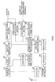
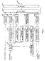
FIG.1 is a block diagram showing the configuration
of a communication terminal according to Embodiment 1
of the present invention. In FIG.1, a communication mode
selector 101 refers to a communication mode table 102
and selects a communication mode based on a CIR measured
by a CIR measurement section 114 described later herein,
and outputs this to a DRC signal creation section 103
and NACK signal counting section 120. Also, based on the
selected communication mode, the communication mode
selector 101 indicates the outbound receive data
demodulation method to an adaptive demodulator 116 and
indicates the outbound receive data decoding method to
an adaptive decoding section 117. The contents of the
communication mode table 102 will be described later
herein.
-
The DRC signal creation section 103 creates a DRC
signal with a number corresponding to the communication
mode output from the communication mode selector 101,
and outputs this signal to a modulator 104.
-
Modulator 104 modulates the DRC signal and outputs
it to a spreader 105. Spreader 105 spreads the output
signal from modulator 104, and outputs the resulting
signal to a multiplexer 108.
-
A modulator 106 modulates an ACK signal or NACK
signal created by a retransmission request signal
creation section 119 described later herein, and outputs
this signal to a spreader 107. Spreader 107 spreads the
output signal from modulator 106, and outputs the
resulting signal to the multiplexer 108.
-
The multiplexer 108 multiplexes the spread DRC
signal and the spread ACK signal or NACK signal, and outputs
them to a transmit RF section 109. The transmit RF section
109 converts the frequency of the output signal from the
multiplexer 108 to radio frequency, and outputs the
resulting signal to a duplexer 110.
-
The duplexer 110 transmits the output signal from
the transmit RF section 109 to the base station as a radio
signal via an antenna 111. In addition, the duplexer 110
outputs a signal transmitted as a radio signal from the
base station and received as a radio signal by the antenna
111 to a receive RF section 112.
-
The receive RF section 112 converts the frequency
of a radio frequency signal output from the duplexer 110
to baseband, and outputs the resulting signal to a
despreader 113 and a despreader 115.
-
Despreader 113 despreads the pilot signal component
of the baseband signal and outputs the resulting signal
to a CIR measurement section 114. The CIR measurement
section 114 measures the CIR of the pilot signal output
from despreader 113, and outputs this to the communication
mode selector 101.
-
Despreader 115 despreads the data component of the
baseband signal and outputs the resulting signal to the
adaptive demodulator 116. The adaptive demodulator 116
demodulates the output signal from despreader 115 in
accordance with the directions of the communication mode
selector 101, and outputs the resulting signal to the
adaptive decoding section 117. The adaptive decoding
section 117 decodes the output signal from the adaptive
demodulator 116 in accordance with the directions of the
communication mode selector 101, and obtains receive
data.
-
An error detection section 118 performs a CRC on
the receive data, and outputs a signal indicating the
CRC result to the retransmission request signal creation
section 119. That is to say, if the CRC result is that
an error has not been detected in the receive data, the
error detection section 118 outputs an OK signal
indicating that an error has not been detected to the
retransmission request signal creation section 119, and
if the CRC result is that an error has been detected in
the receive data, the error detection section 118 outputs
an NG signal indicating that an error has been detected
to the retransmission request signal creation section
119. The retransmission request signal creation section
119 creates an ACK signal if an OK signal is output from
the error detection section 118, or generates a NACK signal
if an NG signal is output from the error detection section
118, and outputs the respective signal to the NACK signal
counting section 120 and modulator 106.
-
The NACK signal counting section 120 counts, for
each communication mode, the number of NACK signals output
before an ACK signal is output from the retransmission
request signal creation section 119. In other words, the
NACK signal counting section 120 counts the number of
data retransmissions for each communication mode. A
table rewriting section 121 compares the number of
retransmissions counted by the NACK signal counting
section 120 with a predetermined threshold value for the
number of retransmissions, and rewrites the contents of
the communication mode table 102 based on the result of
this comparison.
-
Next, the operation of a communication terminal that
has the above configuration will be described.
-
A radio signal transmitted from the base station
is received by the antenna 111 of the communication
terminal, passes through the duplexer 110, and is
frequency-converted to baseband by the receive RF section
112. The baseband signal is despread by despreader 113
and output to the CIR measurement section 114.
-
In the CIR measurement section 114, the CIR of the
pilot signal output from despreader 113 is measured. Then,
in the communication mode selector 101, the communication
mode table 102 is referred to and a communication mode
is selected based onthe CIR measured by the CIR measurement
section 114.
-
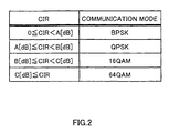
Here, the contents set in the communication mode
table 102 will be described. FIG.2 is a drawing showing
the contents of the communication mode table provided
in a communication terminal according to Embodiment 1
of the present invention. For the sake of explanation,
it is here assumed that communication modes are indicated
only by the modulation method, and that the coding method
is the same for all communication modes.
-
As shown in FIG.2, communication modes are set in
the communication mode table 102 in correspondence to
CIRs, so that a communication mode is selected based on
the pilot signal CIR measured by the CIR measurement
section 114. For example, in the case where the CIR
measured by the CIR measurement section 114 is
A[dB].CIR<B[dB], a communication mode for which the
modulation method is QPSK is selected by the communication
mode selector 101, and a DRC signal with a number
corresponding to the communication mode is created by
the DRC signal creation section 103.
-
The DRC signal is modulated by modulator 104, spread
by spreader 105, and output to the multiplexer 108. In
this stage, only the DRC signal is output from the
multiplexer 108.
-
The DRC signal output from the multiplexer 108 is
frequency-converted to radio frequency by the transmit
RF section 109, and is transmitted to the base station
as a radio signal from the antenna 111 via the duplexer
110.
-
Next, a radio signal transmitted from the base
station in accordance with the communication mode
requested by the communication terminal is received by
the antenna 111 of the communication terminal, passes
through the duplexer 110, and is frequency-converted to
baseband by the receive RF section 112. The baseband
signal is despread by despreader 115, and the data-part
signal is output to the adaptive demodulator 116.
-
In addition, the baseband signal is despread by
despreader 113, and the pilot signal is output to the
CIR measurement section 114. In the CIR measurement
section 114 the CIR of the pilot signal is measured, and
is output to the communication mode selector 101. In the
communication mode selector 101 the communication mode
is selected as described above.
-
The data-part signal is demodulated by the adaptive
demodulator 116 using the demodulation method indicated
by the communication mode selector 101, decoded by the
adaptive decoding section 117 using the decoding method
indicated by the communication mode selector 101, and
output to the error detection section 118.
-
As CRC bits have been added to the data-part signal,
a CRC is carried out on the data-part signal by the error
detection section 118. By this means it is detected
whether or not there is an error in the data-part signal,
and a signal indicating the result of the detection (that
is, an OK signal or an NG signal) is output to the
retransmission request signal creation section 119.
-
In the retransmission request signal creation
section 119, an ACK signal is created if the signal output
from the error detection section 118 is an OK signal,
or a NACK signal is created if the signal output from
the error detection section 118 is an NG signal, and the
created signal is output to the NACK signal counting
section 120 and modulator 106.
-
The ACK signal or NACK signal is modulated by
modulator 106, spread by spreader 107, multiplexed with
the DRC signal by the multiplexer 108, and output to the
transmit RF section 109. The output signal from the
multiplexer 108 is frequency-converted to radio frequency
by the transmit RF section 109, and is transmitted to
the base station as a radio signal from the antenna 111
via the duplexer 110.
-
In the NACK signal counting section 120, the number
of times a NACK signal is output from the retransmission
request signal creation section 119 is counted for the
currently selected communication mode.
-
Then, in the base station, if an ACK signal is
received the next data is transmitted to the communication
terminal, or if a NACK signal is received the same data
as previously transmitted is retransmitted to the
communication terminal.
-
As a result of repeating the above-described
operations, the NACK signal counting section 120 counts,
for the currently selected communication mode, the number
of NACK signals output before an ACK signal is output
from the retransmission request signal creation section
119. That is to say, in the NACK signal counting section
120 the number of retransmissions of data transmitted
from the base station is successively counted for the
currently selected communication mode. When an ARQ
signal is output from the retransmission request signal
creation section 119, the NACK signal counting section
120 count result is reset to 0.
-
Then, in the table rewriting section 121, the number
of retransmissions counted by the NACK signal counting
section 120 is compared with a predetermined threshold
value N, and the contents of the communication mode table
102 are rewritten based on the result of this comparison.
Here, the operation of the table rewriting section 121
will be described. FIG.3 is an operational flowchart for
explaining the operation of the table rewriting section
provided in a communication terminal according to
Embodiment 1 of the present invention.
-
In the table rewriting section 121, the number of
retransmissions counted by the NACK signal counting
section 120 is compared with a predetermined threshold
value N in Step (hereinafter abbreviated to "ST") 201.
Here, the threshold value N is the maximum number of
retransmissions permitted in the system, and this
permissible value N is predetermined based on the desired
reception quality of data-part signals required in the
system.
-
If, in ST201, the number of retransmissions is less
than N, the data-part signal reception quality can be
said to be excessive quality that exceeds the desired
reception quality required in the system. That is to say,
the current actual downlink channel quality can be
considered to have improved since the point at which
channel quality was measured by the CIR measurement
section 114. It can therefore be determined that, with
the current actual downlink channel quality,
communication can be performed using a communication mode
with a higher transmission rate than the communication
mode selected based on the pilot signal CIR.
-
Thus, if the number of retransmissions is less than
N in ST201, the contents of the communication mode table
102 shown in FIG.2 are rewritten as shown in ST202 by
the table rewriting section 121. That is to say, A[dB],
B[dB], and C[dB] set in the communication mode table 102
shown in FIG.2 are decremented respectively by
predetermined values X[dB], Y[dB], and Z[dB]. As a result,
the communication mode selector 101 selects a
communication mode with a higher transmission rate than
the previously selected communication mode, even if the
pilot signal CIR measured by the CIR measurement section
114 is the same.
-
If, on the other hand, the number of retransmissions
is greater than N in ST201, the data-part signal reception
quality can be said not to attain the desired reception
quality required in the system. That is to say, the
current actual downlink channel quality can be considered
to have degraded since the point at which channel quality
was measured by the CIR measurement section 114. It can
therefore be determined that, with the current actual
downlink channel quality, it is necessary for
communication to be performed using a communication mode
with a lower transmission rate than the communication
mode selected based on the pilot signal CIR.
-
Thus, if the number of retransmissions is greater
than N in ST201, the contents of the communication mode
table 102 shown in FIG.2 are rewritten as shown in ST204
by the table rewriting section 121. That is to say, A[dB],
B[dB], and C[dB] set in the communication mode table 102
shown in FIG.2 are incremented respectively by
predetermined values X[dB], Y[dB], and Z[dB]. As a result,
the communication mode selector 101 selects a
communication mode with a lower transmission rate than
the previously selected communication mode, even if the
pilot signal CIR measured by the CIR measurement section
114 is the same.
-
If the number of retransmissions is equal to N in
ST201, the data-part signal reception quality can be said
to be on a level with the desired reception quality required
in the system, and therefore the contents of the
communication mode table are not rewritten, as shown in
ST203.
-
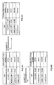
Actual examples of the communication mode table
rewrite operations described above are illustrated in
FIG.4A through FIG.4C. FIG.4A through FIG.4C are
drawings showing examples of communication mode table
rewrite operations by the table rewriting section of a
communication terminal according to Embodiment 1 of the
present invention. Explanations are given here for the
case where A[dB], B[dB], and C[dB] currently set in the
communication mode table 102 shown in FIG.2 are 4[dB],
8[dB], and 12[dB], respectively, and variation amounts
X[dB], Y[dB], and Z[dB] are all 1[dB].
-
First, in FIG.4A, A[dB], B[dB], and C[dB] are set
to 4[dB], 8[dB], and 12[dB], respectively. Then, if the
number of retransmissions is less than N, A[dB], B[dB],
and C[dB] are all decremented by 1[dB] each, and the
communication mode table 102 is rewritten as shown in
FIG.4B. If, on the other hand, the number of
retransmissions is greater than N, A[dB], B[dB], and C[dB]
are all incremented by 1[dB] each, and the communication
mode table 102 is rewritten as shown in FIG.4C.
-
In this way, based on the number of retransmissions
of a data-part signal (that is, the data-part signal
reception quality), the table rewriting section 121
detects that a difference has arisen between the channel
quality measured by the CIR measurement section 114 and
the current actual channel quality, and rewrites the
contents of the communication mode table 102.
-
Thus, according to this embodiment, the reception
quality of a data-part signal is determined by the number
of times a NACK signal is sent back, and the contents
of a communication mode table indicating the
correspondence between downlink channel quality and
communication modes are rewritten based on the number
of times a NACK signal is sent back, thereby making it
possible to select a communication mode that enables
communication to be performed most efficiently with the
current actual channel quality.
-
Also, according to this embodiment, data-part
signal reception quality is determined according to the
number of retransmissions based on a CRC, so that reception
quality determination can be performed quickly and easily,
enabling communication mode table rewrites to be
performed at high-speed, keeping up with variations in
channel quality.
-
Moreover, according to this embodiment,
communication mode table rewrites are performed with
reference to a maximum number of retransmissions
permitted in the system. In other words, communication
mode table rewrites are performed with reference to a
desired reception quality required in the system. Thus,
according to this embodiment, it is possible to perform
downlink data communication while maintaining the desired
reception quality required in the system.
-
In this embodiment, it is also possible for the NACK
signal counting section 120 to calculate an average value
of the number of retransmissions at predetermined
intervals for each communication mode, and for the table
rewriting section 121 to rewrite the communication mode
table 102 based on the result of a comparison between
that average value of the number of retransmissions and
a predetermined threshold value N. The reliability of
the number of retransmissions is improved by calculating
an average value of the number of retransmissions in this
way, enabling communication mode table rewrites to be
performed accurately and without errors.
(Embodiment 2)
-
A communication terminal according to Embodiment
2 of the present invention determines the reception
quality of a data-part signal by means of the error rate,
and based on this error rate, rewrites the contents of
a communication mode table indicating the correspondence
between downlink channel quality and communication modes.
-
FIG.5 is a block diagram showing the configuration
of a communication terminal according to Embodiment 2
of the present invention. As shown in this figure, a
communication terminal according to this embodiment
differs from the communication terminal shown in FIG.1
in being provided with an error rate calculation section
301 and table rewriting section 302 instead of an error
detection section 118, retransmission request signal
creation section 119, NACK signal counting section 120,
and table rewriting section 121. In the following
description, parts identical to those in FIG.1 are
assigned the same codes as in FIG.1 and their detailed
explanations are omitted.
-
In FIG.5, a communication mode selector 101 refers
to a communication mode table 102 and selects a
communication mode based on a CIR measured by a CIR
measurement section 114, and outputs this to a DRC signal
creation section 103 and the error rate calculation
section 301.
-
The error rate calculation section 301 calculates
the error rate of the data-part signal output from an
adaptive decoding section 117 for each communication mode,
and outputs this to the table rewriting section 302. Here,
the Bit Error Rate (BER) or BLock Error Rate (BLER) is
used as the error rate calculated by the error rate
calculation section 301. The bit error rate can be
calculated by comparing data-part signals before and
after error correction to detect a bit in which an error
has occurred, and the block error rate can be calculated
by performing a CRC to detect a block in which an error
has occurred. The bit error rate has the advantage of
more accurately indicating the reception quality of a
data-part signal than the block error rate, while the
block error rate has the advantage of being able to be
calculated with a simpler equipment configuration than
the bit error rate.
-
The table rewriting section 302 compares the error
rate calculated by the error rate calculation section
301 with a predetermined error rate threshold value, and
rewrites the contents of the communication mode table
102 based on the result of the comparison. Here, the
predetermined threshold value is the error rate permitted
in the system, this permissible value being determined
beforehand based on the desired data-part signal
reception quality required in the system.
-
If the error rate calculated by the error rate
calculation section 301 is lower than the predetermined
threshold value, the data-part signal reception quality
can be said to be excessive quality that exceeds the desired
reception quality required in the system. That is to say,
the current actual downlink channel quality can be
considered to have improved since the point at which
channel quality was measured by the CIR measurement
section 114. It can therefore be determined that, with
the current actual downlink channel quality,
communication can be performed using a communication mode
with a higher transmission rate than the communication
mode selected based on the pilot signal CIR.
-
Thus, if the error rate calculated by the error rate
calculation section 301 is lower than the predetermined
threshold value, A[dB], B[dB], and C[dB] set in the
communication mode table 102 shown in FIG.2 are
decremented by the table rewriting section 302 by
predetermined values X[dB], Y[dB], and Z[dB],
respectively, in the same way as in above-described
Embodiment 1.
-
If, on the other hand, the error rate calculated
by the error rate calculation section 301 is higher than
the predetermined threshold value, the data-part signal
reception quality can be said not to attain the desired
reception quality required in the system. That is to say,
the current actual downlink channel quality can be
considered to have degraded since the point at which
channel quality was measured by the CIR measurement
section 114. It can therefore be determined that, with
the current actual downlink channel quality, it is
necessary for communication to be performed using a
communication mode with a lower transmission rate than
the communication mode selected based on the pilot signal
CIR.
-
Thus, if the error rate calculated by the error rate
calculation section 301 is higher than the predetermined
threshold value, A[dB], B[dB], and C[dB] set in the
communication mode table 102 shown in FIG.2 are
incremented by the table rewriting section 302 by
predetermined values X[dB], Y[dB], and Z[dB],
respectively, in the same way as in above-described
Embodiment 1.
-
In this way, based on the error rate of a data-part
signal (that is, the data-part signal reception quality),
the table rewriting section 302 detects that a difference
has arisen between the channel quality measured by the
CIR measurement section 114 and the current actual channel
quality, and rewrites the contents of the communication
mode table 102.
-
Thus, according to this embodiment, the reception
quality of a data-part signal is determined by the error
rate, and the contents of a communication mode table
indicating the correspondence between downlink channel
quality and communication modes are rewritten based on
this error rate, thereby making it possible to select
a communication mode that enables communication to be
performed most efficiently with the current actual
channel quality.
-
Also, according to this embodiment, determining
data-part signal reception quality by means of the error
rate enables data-part signal reception quality to be
determined more accurately. Therefore, communication
mode table rewrites can be performed accurately and
without errors.
(Embodiment 3)
-
A communication terminal according to Embodiment
3 of the present invention determines the reception
quality of a data-part signal by means of data-part signal
throughput, and based on this throughput, rewrites the
contents of a communication mode table indicating the
correspondence between downlink channel quality and
communication modes.
-
FIG.6 is a block diagram showing the configuration
of a communication terminal according to Embodiment 3
of the present invention. As shown in this figure, a
communication terminal according to this embodiment
differs from the communication terminal shown in FIG.1
in being provided with a throughput calculation section
401 and table rewriting section 402 instead of an error
detection section 118, retransmission request signal
creation section 119, NACK signal counting section 120,
and table rewriting section 121. In the following
description, parts identical to those in FIG.1 are
assigned the same codes as in FIG.1 and their detailed
explanations are omitted.
-
In FIG.6, a communication mode selector 101 refers
to a communication mode table 102 and selects a
communication mode based on a CIR measured by a CIR
measurement section 114, and outputs this to a DRC signal
creation section 103, the throughput calculation section
401, and the table rewriting section 402.
-
The throughput calculation section 401 calculates
the average throughput of the data-part signal output
from an adaptive decoding section 117 at predetermined
intervals for each communication mode, and outputs this
to the table rewriting section 402. As [Mbps] is normally
used as the unit of throughput, the throughput calculation
section 401 can calculate the average data-part signal
throughput by finding the average number of data-part
signal bits received per second.
-
The table rewriting section 402 compares the average
throughput calculated by the throughput calculation
section 401 with a predetermined throughput threshold
value, and rewrites the contents of the communication
mode table 102 based on the result of the comparison.
One method of calculating the predetermined throughput
value is described below.
-
If the number of terminals currently simultaneously
communicating with a base station (hereinafter referred
to as "number of simultaneously communicating terminals")
is N, of the signals transmitted from the base station,
on average 1/N can be assumed to be signals transmitted
to the terminal being considered. Therefore, if a
communication mode is selected that is expected to enable
a throughput of 2[Mbps] to be attained, for example, an
average throughput of 1.2/N[Mbps] can be expected to be
attained by a communication terminal for which that mode
is selected. This 1.2/N[Mbps] throughput is then the
above-mentioned predetermined threshold value.
-
Thus, the table rewriting section 402 calculates
a predetermined threshold value for each communication
mode based on the communication mode output from the
communication mode selector 101 and the number of
simultaneously communicating terminals, and compares the
average throughput calculated for each communication mode
by the throughput calculation section 401 with the
corresponding predetermined threshold value. It is
assumed that terminals are notified of the number of
simultaneously communicating terminals by the base
station.
-
The predetermined throughput threshold value is not
limited to that described above, but may, for example,
be determined beforehand on the basis of desired data-part
signal reception quality required in the system, as in
above-described Embodiments 1 and 2.
-
If the average throughput calculated by the
throughput calculation section 401 is higher than the
predetermined threshold value, the current actual
downlink channel quality can be considered to have
improved since the point at which channel quality was
measured by the CIR measurement section 114. It can
therefore be determined that, with the current actual
downlink channel quality, communication can be performed
using a communication mode with a higher transmission
rate than the communication mode selected based on the
pilot signal CIR.
-
Thus, if the average throughput calculated by the
throughput calculation section 401 is higher than the
predetermined threshold value, A[dB], B[dB], and C[dB]
set in the communication mode table 102 shown in FIG.2
are decremented by the table rewriting section 402 by
predetermined values X[dB], Y[dB], and Z[dB],
respectively, in the same way as in above-described
Embodiment 1.
-
If, on the other hand, the average throughput
calculated by the throughput calculation section 401 is
lower than the predetermined threshold value, the current
actual downlink channel quality can be considered to have
degraded since the point at which channel quality was
measured by the CIR measurement section 114. It can
therefore be determined that, with the current actual
downlink channel quality, it is necessary for
communication to be performed using a communication mode
with a lower transmission rate than the communication
mode selected based on the pilot signal CIR.
-
Thus, if the average throughput calculated by the
throughput calculation section 401 is lower than the
predetermined threshold value, A[dB], B[dB], and C[dB]
set in the communication mode table 102 shown in FIG.2
are incremented by the table rewriting section 402 by
predetermined values X[dB], Y[dB], and Z[dB],
respectively, in the same way as in above-described
Embodiment 1.
-
In this way, based on the average throughput of a
data-part signal (that is, the data-part signal reception
quality), the table rewriting section 402 detects that
a difference has arisen between the channel quality
measured by the CIR measurement section 114 and the current
actual channel quality, and rewrites the contents of the
communication mode table 102.
-
Thus, according to this embodiment, the reception
quality of a data-part signal is determined by the
data-part signal throughput, and the contents of a
communication mode table indicating the correspondence
between downlink channel quality and communication modes
are rewritten based on this throughput, thereby making
it possible to select a communication mode that enables
communication to be performed most efficiently with the
current actual channel quality.
-
Also, throughput is a value that indicates actual
reception quality in a communication terminal more
accurately than the number of retransmissions or the error
rate. Therefore, rewriting the communication mode table
based on throughput enables communication mode table
rewrites to be performed more accurately.
(Embodiment 4)
-
In above-described Embodiments 1 to 3, a
communication terminal selects a communication mode based
on the pilot signal CIR, and transmits a DRC signal
corresponding to that selected communication mode to the
base station. DRC signal information can be represented
with far fewer bits than other information indicating
downlink channel quality (such as a downlink CIR, for
example), and therefore use of a DRC signal has the
advantage of enabling the downlink channel utilization
ratio to be increased. On the other hand, since a
communication terminal has to select the communication
mode and create a DRC signal, and must be provided with
a table for communication mode selection, a table for
DRC signal creation, and so forth, there are the
disadvantages of increased communication terminal power
consumption and equipment scale.
-
Thus, in the embodiment described below, a
communication terminal transmits a CIR signal indicating
the pilot signal CIR to the base station, and the base
station refers to a communication mode table and selects
a communication mode based on the CIR. As a result,
although there is the disadvantage of a slight decrease
in the uplink channel utilization ratio, the fact that
communication terminals do not have to select the
communication mode and create a DRC signal, and do not
need to be provided with a communication mode selection
table, DRC signal creation table, and so forth, offers
the major advantage of enabling communication terminal
power consumption and equipment scale to be reduced. Also,
in the embodiment described below, it is possible for
CIRs transmitted from a plurality of terminals to be
compared in the base station, and the correct
communication mode to be determined with certainty,
making the embodiment described below particularly useful
in cases such as those where it is not possible for the
communication mode to be determined simply from the CIR
in each communication terminal.
-
This embodiment will be described below. A base
station according to Embodiment 4 rewrites the contents
of a communication mode table indicating the
correspondence between downlink channel quality and
communication modes based on the number of times a NACK
signal is sent back from a communication terminal.
-
FIG.7 is a block diagram showing the configuration
of a communication terminal that performs radio
communication with a base station according to Embodiment
4 of the present invention. In the following description,
parts identical to those in FIG.1 are assigned the same
codes as in FIG.1 and their detailed explanations are
omitted.
-
In FIG.7, a CIR signal creation section 501 creates
a CIR signal that indicates the pilot signal CIR measured
by a CIR measurement section 114, and outputs this signal
to a modulator 104. Modulator 104 modulates the CIR
signal and outputs it to a spreader 105.
-
A despreader 502 despreads a baseband signal
with the spreading code used to despread a signal
indicating the communication mode, and outputs the
despread signal to a communication mode detection section
503. The communication mode detection section 503
demodulates the output signal from the despreader 502
and detects the communication mode. Then, based on the
detected communication mode, the communication mode
detection section 503 indicates the outbound receive data
demodulation method to an adaptive demodulator 116 and
indicates the outbound receive data decoding method to
an adaptive decoding section 117.
-
FIG.8 is a block diagram showing the configuration
of a base station according to Embodiment 4 of the present
invention.
-
In FIG.8, an allocation section 601 determines
communication resource allocation to each communication
terminal based on a CIR indicated by a CIR signal extracted
by a demodulator 616 described later herein. Then, based
on the determined communication resource allocation, the
allocation section 601 gives an instruction to a buffer
606 for output of outbound transmit data, and outputs
the CIR signal to a communication mode selector 602.
-
The communication mode selector 602 refers to a
communication mode table 603, selects a communication
mode based on the CIR indicated by the CIR signal output
from the allocation section 601, and outputs a signal
indicating that communication mode to a modulator 604
and NACK signal counting section 619. Also, based on the
selected communication mode, the communication mode
selector 602 indicates the outbound transmit data coding
method to an adaptive coding section 607 and indicates
the outbound transmit data modulation method to an
adaptive modulator 608. The contents set in the
communication mode table 603 are identical to those shown
in FIG.2, and therefore a description thereof will be
omitted here. A communication mode table 603 is provided
for each communication terminal.
-
The modulator 604 modulates the signal indicating
the communication mode, and outputs it to a spreader 605.
Spreader 605 spreads the output signal from the modulator
604 and outputs the resulting signal to a multiplexer
610. The buffer 606 holds outbound transmit data, and
outputs outbound transmit data for a predetermined
communication terminal to the adaptive coding section
607 in accordance with directions from the allocation
section 601. The adaptive coding section 607 codes the
output signal from the buffer 606 in accordance with
directions from the communication mode selector 602, and
outputs the resulting signal to the adaptive modulator
608. The adaptive modulator 608 modulates the output
signal from the adaptive coding section 607 in accordance
with directions from the communication mode selector 602,
and outputs the resulting signal to a spreader 609.
Spreader 609 spreads the output signal from the adaptive
modulator 608, and outputs the resulting signal to the
multiplexer 610. The multiplexer 610 multiplexes the
signal indicating the communication mode with outbound
transmit data, and outputs the resulting signal to a
receive RF section 611. The receive RF section 611
converts the frequency of the output signal from the
multiplexer 610 to radio frequency and outputs it to a
duplexer 612.
-
The duplexer 612 transmits the output signal from
the transmit RF section 611 to the communication terminals
as a radio signal via an antenna 613. In addition, the
duplexer 612 outputs a signal transmitted as a radio signal
from a communication terminal and received as a radio
signal by the antenna 613 to a receive RF section 614.
The receive RF section 614 converts the frequency of a
radio frequency signal output from the duplexer 612 to
baseband, and outputs the resulting signal to a despreader
615 and a despreader 617. Despreader 615 despreads the
baseband signal with the spreading code used to spread
the CIR signal, and outputs the resulting signal to a
demodulator 616. Demodulator 616 demodulates the output
signal from despreader 615 and extracts the CIR signal,
which it outputs to the allocation section 601.
-
Despreader 617 despreads the baseband signal with
the spreading code used to spread an ACK signal or NACK
signal, and outputs the resulting signal to a demodulator
618. Demodulator 618 demodulates the output signal from
despreader 617 and extracts an ACK signal or NACK signal,
which it outputs to the NACK signal counting section 619.
The NACK signal counting section 619 counts, for each
communication mode, the number of NACK signals output
before an ACK signal is output from demodulator 618. In
other words, the NACK signal counting section 619 counts
the number of data retransmissions for each communication
mode.
-
A despreader 615, demodulator 616, despreader 617,
demodulator 618, and NACK signal counting section 619
are provided for each communication terminal. A CIR
signal for each communication terminal is output from
the corresponding demodulator 616, and the number of data
retransmissions is counted by the respective NACK signal
counting sections 619 for each communication terminal
and for each communication mode.
-
A table rewriting section 620 compares the number
of retransmissions counted by the NACK signal counting
section 619 with a predetermined threshold value for the
number of retransmissions, and rewrites the contents of
the communication mode table 603 for the relevant
communication terminal based on the result of this
comparison.
-
Next, the operation of a base station with the above
configuration will be described.
-
An ACK signal or NACK signal transmitted from a
communication terminal is demodulated by demodulator 618
and output to the NACK signal counting section 619. In
the NACK signal counting section 619, the number of NACK
signals output before an ACK signal is output from
demodulator 618 is counted for the currently selected
communication mode. That is to say, in the NACK signal
counting section 619 the number of retransmissions of
data to the communication terminal is successively
counted for the currently selected communication mode.
When an ARQ signal is output from demodulator 618, the
NACK signal counting section 619 count result is reset
to 0.
-
Then, in the table rewriting section 620, the number
of retransmissions counted by the NACK signal counting
section 619 is compared with a predetermined threshold
value N, and the contents of the communication mode table
603 for the relevant communication terminal are rewritten
based on the result of this comparison. The table
rewriting section 603 rewrite operation is as described
in Embodiment 1 above, and so a description of this
operation will be omitted here.
-
Thus, according to this embodiment, in the same way
as in above-described Embodiment 1, the contents of a
communication mode table indicating the correspondence
between downlink channel quality and communication modes
are rewritten based on the number of times a NACK signal
is sent back from a communication terminal, thereby
enabling the same kind of effect to be obtained as with
above-described Embodiment 1.
(Embodiment 5)
-
A communication terminal according to Embodiment
5 of the present invention rewrites the contents of a
communication mode table indicating the correspondence
between downlink channel quality and communication modes
based on the data-part signal error rate notified by a
communication terminal.
-
A base station according to this embodiment will
be described below. FIG.9 is a block diagram showing the
configuration of a communication terminal that performs
radio communication with a base station according to
Embodiment 5 of the present invention. In the following
description, parts identical to those in FIG.7 are
assigned the same codes as in FIG.7 and their detailed
explanations are omitted.
-
In FIG.9, an error rate detection section 701 detects
the error rate of a data-part signal output from an adaptive
decoding section 117, and outputs this to a notification
signal creation section 702. The detailed operation of
the error rate detection section 701 is as described in
Embodiment 2 above, and so a description of this operation
will be omitted here.
-
The notification signal creation section 702
creates a signal indicating the error rate and outputs
this signal to a modulator 106. The signal indicating
the error rate is modulated by modulator 106, spread by
a spreader 107, multiplexed with a CIR signal by a
multiplexer 108, and transmitted to the base station.
-
FIG. 10 is a block diagram showing the configuration
of a base station according to Embodiment 5 of the present
invention. In the following description, parts
identical to those in FIG.8 are assigned the same codes
as in FIG.8 and their detailed explanations are omitted.
-
In FIG.10, a communication mode selector 602 outputs
a signal indicating the selected communication mode to
a modulator 604 and error rate detection section 802.
A despreader 801 despreads a baseband signal with the
spreading code used to spread the signal indicating the
error rate, and outputs the resulting signal to the error
rate detection section 802. The error rate detection
section 802 demodulates the output signal from the
despreader 801 and extracts the signal indicating the
error rate, and detects the error rate of the data-part
signal in each communication terminal for each
communication mode.
-
A despreader 615, demodulator 616, despreader 801,
and error rate detection section 802 are provided for
each communication terminal. A CIR signal for each
communication terminal is output from the corresponding
demodulator 616, and the data-part signal error rate is
detected by the respective error rate detection section
802 for each communication terminal and for each
communication mode.
-
A table rewriting section 803 compares the error
rate detected by the error rate detection section 802
with a predetermined error rate threshold value, and
rewrites the contents of the communication mode table
603 for the relevant communication terminal based on the
result of this comparison.
-
Next, the operation of a base station with the above
configuration will be described.
-
A signal indicating the error rate transmitted from
a communication terminal is demodulated by the error rate
detection section 802. By this means the data-part signal
error rate is detected. The detected error rate is output
to the table rewriting section 803.
-
Then, in the table rewriting section 803, the error
rate detected by the error rate detection section 802
is compared with a predetermined threshold value, and
the contents of the communication mode table 603 for the
relevant communication terminal are rewritten based on
the result of this comparison. The table rewriting
section 603 rewrite operation by the table rewriting
section 803 is as described in Embodiment 2 above, and
so a description of this operation will be omitted here.
-
Thus, according to this embodiment, in the same way
as in above-described Embodiment 2, the contents of a
communication mode table indicating the correspondence
between downlink channel quality and communication modes
are rewritten based on the data-part signal error rate
notified by a communication terminal, thereby enabling
the same kind of effect to be obtained as with
above-described Embodiment 2.
(Embodiment 6)
-
A communication terminal according to Embodiment
6 of the present invention rewrites the contents of a
communication mode table indicating the correspondence
between downlink channel quality and communication modes
based on data-part signal throughput notified by a
communication terminal.
-
A base station according to this embodiment will
be described below. FIG.11 is a block diagram showing
the configuration of a communication terminal that
performs radio communication with a base station
according to Embodiment 6 of the present invention. In
the following description, parts identical to those in
FIG.7 are assigned the same codes as in FIG.7 and their
detailed explanations are omitted.
-
In FIG.11, a throughput calculation section 901
calculates the average throughput of the data-part signal
output from an adaptive decoding section 117 at
predetermined intervals, and outputs this to a
notification signal creation section 902. The method of
calculating the average throughput is as described in
Embodiment 3 above, and so a description of this method
will be omitted here.
-
The throughput calculation section 901 creates a
signal indicating the average throughput and outputs this
signal to a modulator 106. The signal indicating the
average throughput is modulated by modulator 106, spread
by a spreader 107, multiplexed with a CIR signal by a
multiplexer 108, and transmitted to the base station.
-
FIG.12 is a block diagram showing the configuration
of a base station according to Embodiment 6 of the present
invention. In the following description, parts
identical to those in FIG.8 are assigned the same codes
as in FIG.8 and their detailed explanations are omitted.
-
In FIG.12, a communication mode selector 602 outputs
a signal indicating the selected communication mode to
a modulator 604 and throughput detection section 1002.
A despreader 1001 despreads a baseband signal with the
spreading code used to spread the signal indicating the
average throughput, and outputs the resulting signal to
the throughput detection section 1002. The throughput
detection section 1002 demodulates the output signal from
the despreader 1001 and extracts the signal indicating
the average throughput, and detects the average
throughput of the data-part signal in each communication
terminal for each communication mode.
-
A despreader 615, demodulator 616, despreader 1001,
and throughput detection section 1002 are provided for
each communication terminal. A CIR signal for each
communication terminal is output from the corresponding
demodulator 616, and the data-part signal average
throughput is detected by the respective throughput
detection section 1002 for each communication terminal
and for each communication mode.
-
A table rewriting section 1003 compares the average
throughput detected by the throughput detection section
1002 with a predetermined throughput threshold value,
and rewrites the contents of the communication mode table
603 for the relevant communication terminal based on the
result of this comparison.
-
Next, the operation of a base station with the above
configuration will be described.
-
A signal indicating the average throughput
transmitted from a communication terminal is demodulated
by the throughput detection section 1002. By this means
the data-part signal average throughput is detected. The
detected average throughput is output to the table
rewriting section 1003.
-
Then, in the table rewriting section 1003, the
average throughput detected by the throughput detection
section 1002 is compared with a predetermined threshold
value, and the contents of the communication mode table
603 for the relevant communication terminal are rewritten
based on the result of this comparison. The table
rewriting section 603 rewrite operation by the table
rewriting section 1003 is as described in Embodiment 3
above, and so a description of this operation will be
omitted here.
-
Thus, according to this embodiment, in the same way
as in above-described Embodiment 3, the contents of a
communication mode table indicating the correspondence
between downlink channel quality and communication modes
are rewritten based on data-part signal throughput
notified by a communication terminal, thereby enabling
the same kind of effect to be obtained as with
above-described Embodiment 3.
-
In above-described Embodiments 1 to 6, the CIR of
a pilot signal is used as a value indicating downlink
channel quality, but this is not a limitation, and any
value may be used as long as it is a value that indicates
channel quality.
-
Also , in above Embodiments 1 to 6, in order to prevent
the communication mode table from being rewritten
frequently, a threshold value given a predetermined width
may be set as the threshold value to be compared with
the number of retransmissions, error rate, or average
throughput. For example, it is possible to set two new
threshold values incremented/decremented by ±X with
respect to the threshold value used in above Embodiments
1 to 6, and to arrange for rewriting of the communication
mode table not be performed if the number of
retransmissions, error rate, or average throughput is
within a range of ±X with respect to the threshold value
used in above Embodiments 1 to 6.
-
Moreover, in above Embodiments 1 to 6, a threshold
value to be compared with the number of retransmissions,
error rate, or average throughput may be set for each
communication mode.
-
Furthermore, in above Embodiments 1 to 3, a
communication terminal may be notified by the base station
of the threshold value to be compared with the number
of retransmissions, error rate, or average throughput.
-
In addition, in above Embodiments 1 to 6, all the
CIR values set in the communication mode table are
rewritten when the communication mode table is rewritten,
but a particular CIR value or plurality of CIR values
may be rewritten instead.
-
Also, in above Embodiments 1 to 6, the variation
widths of the CIR values set in the communication mode
table are assumed to be fixed values (X[dB], Y[dB], and
Z[dB]), but it is also possible for variation widths to
be varied adaptively according to the size of the
difference between the measured channel quality and the
current actual channel quality.
-
Moreover, in above Embodiments 1 to 6, the fact that
a difference has arisen between the measured channel
quality and the current actual channel quality is detected
on the basis of data-part signal channel quality, but
this is not a limitation, and any method may be used as
long as it is a method that can detect the fact that a
difference has arisen.
-
Thus, according to above Embodiments 1 to 6, in a
communication system in which communication resources
are allocated to communication terminals by time division
based on downlink channel quality measured from a pilot
signal, the correspondence between downlink channel
quality and communication modes is rewritten when a
difference arises between the measured channel quality
and the current actual channel quality, thereby making
it possible to select a communication mode that enables
communication to be performed most efficiently with the
current actual channel quality. Thus, according to the
present invention, it is possible to prevent a fall in
downlink throughput.
(Embodiment 7)
-
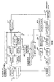
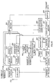
FIG.13 is a block diagram showing the configuration
of a base station according to Embodiment 7 of the present
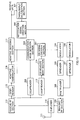
invention, and FIG.14 is a block diagram showing the
configuration of a communication terminal according to
Embodiment 7 of the present invention.
-
First, in a modulator/spreader 1204 of the base
station shown in FIG. 13, a pilot burst signal is modulated
and then spread. This spread pilot burst signal is
multiplexed with other signals by a multiplexer 1203,
and the resulting signal undergoes predetermined
transmission processing such as up-conversion by an RF
section 1202, and is then transmitted from an antenna
1201.
-
This signal is received by the antenna 1301 of the
communication terminal shown in FIG.14, undergoes
predetermined reception processing such as
down-conversion by an RF section 1302, and is then output
to a despreader/demodulator 1303. In the
despreader/demodulator 1303, the received signal is
despread and then demodulated, and is output to a CRC
section 1304 and CIR measurement section 1306.
-
In the CIR measurement section 1306, the reception
quality-to be specific, the CIR-of the pilot burst signal
in the demodulated received signal is measured. The
measured CIR is output to a rate request value
determination section 1307. The correspondence between
CIRs and transmission rates has been stored beforehand
in the rate request value determination section 1307,
and the transmission rate corresponding to the measured
CIR is selected by the CIR measurement section 1306. This
selected transmission rate is then output to a multiplexer
1309 as the rate request value of this terminal.
-
In the multiplexer 1309, the rate request value and
transmit data from this terminal are multiplexed, and
this multiplex signal is modulated and then spread by
a modulator/spreader 1310. This spread signal undergoes
predetermined transmission processing by the RF section
1302, and is then transmitted from the antenna 1301.
-
This signal is received by the antenna 1201 of the
base station shown in FIG.13, undergoes predetermined
reception processing by the RF section 1202, and is then
output to a despreader/demodulator 1208. In the
despreader/demodulator 1208, the received signal is
despread and then demodulated, and is output to a TPC
signal generation section 1211 and radio resource
management section 1212.
-
In the TPC signal generation section 1211, a TPC
signal for controlling terminal transmission power is
generated using a pilot symbol included in the demodulated
signal. This TPC signal is assembled into a MAC channel
signal by a MAC channel assembly section 1210. The MAC
channel signal is modulated and then spread by a
modulator/spreader 1206, and is output to the multiplexer
1203.
-
In the radio resource management section 1212, the
communication terminal that transmitted the largest rate
request value among the rate request values from all the
communication terminals is selected, and the result of
this selection is output to a buffer section 1216,
dedicated channel coding section 1209, and
modulator/spreader 1205. The selection method may also
be to select the communication terminal that requested
the lowest transmission rate, so that communication is
possible for all communication terminals. There are no
particular restrictions on the selection method.
-
Transmit data for this selected communication
terminal is read in the buffer section 1216. Then, in
the dedicated channel coding section 1209, address
information indicating which communication terminal this
transmit data is destined for is added to this read transmit
data. Then the data with address information added is
modulated and then spread by modulator/spreader 1205,
and is output to the multiplexer 1203. Each of the signals
output to multiplexer 1203 is multiplexed and then
transmitted from the RF section 1202 via the antenna 1201.
-
When this signal is received by the communication
terminal shown in FIG.14, if address information for this
terminal is received, the signal following the address
information is received. Then a CRC is performed on the
receive data by the CRC section 1304. If the result of
this CRC is OK, the receive data is output via a
decomposition section 1305 to a latter-stage circuit (not
shown). If the result of this CRC is NG, on the other
hand, the receive data is not output to the decomposition
section 1305. The CRC result (OK or NG) is transmitted
to the base station shown in FIG.13 via the multiplexer
1309, modulator/spreader 1310, RF section 1302, and
antenna 1301.
-
When this CRC result (OK or NG) is received by the
base station shown in FIG.13, it is input to a downlink
error measurement section 1213. In the downlink error
measurement section 1213, the error rate of signal
transmission to the communication terminal is estimated
from this CRC result, and this error rate is output to
a rate change request section 1214.
-
Estimation of the error rate is performed as follows .
The number of NGs within a predetermined interval is
counted for each communication terminal and for each
allocated data rate. Similarly, the number of times
allocated is counted. Then the result of dividing the
number of NGs by the number of times allocated is taken
as the error rate estimate.
-
In the rate change request section 1214, the error
rate is compared with a predetermined first threshold
value and a predetermined second threshold value. It is
assumed that the second threshold value is a lower value
than the first threshold value. It is also assumed that
the second threshold value is greater than zero and almost
zero.
-
Then, in the rate change request section 1214, if
the error rate is outside the predetermined range-that
is, greater than or equal to the first threshold value
or less than or equal to the second threshold value-it
is determined that the transmission rate determined from
the CIR by the rate request value determination section
1307 is incorrect. That is to say, it is determined that
the rate request value from the communication terminal
is incorrect.
-
In other words, in the rate change request section
1214, if the error rate is greater than or equal to the
first threshold value, it is determined that the rate
request value is too high and the desired communication
quality cannot be attained at that transmission rate.
In this case, therefore, a signal instructing the
communication terminal to lower the rate request value
below the transmission rate determined from the CIR is
generated by the rate change request section 1214 as a
rate change instruction signal. In this way the base
station can cause the transmission rate requested by the
communication terminal to be changed to a transmission
rate that meets the desired communication quality.
-
If, on the other hand, the error rate is less than
or equal to the second threshold value, it is determined
that the rate request value from the communication
terminal is too low and communication quality is excessive
at that transmission rate. In this case, therefore, a
signal instructing the communication terminal to raise
the rate request value above the transmission rate
determined from the CIR is generated by the rate change
request section 1214 as a rate change instruction signal.
In this way the base station can cause the transmission
rate requested by the communication terminal to be changed
to a transmission rate at which data communication can
be performed more efficiently.
-
Determination and rate change instruction
operations performed by the rate change request section
1214 may be divided between two component sections (a
determination section and a changing section).
-
A rate change instruction signal generated by the
rate change request section 1214 is assembled into a
control channel signal by a control channel assembly
section 1215. The control channel signal is modulated
and then spread by a modulator/spreader 1207, and
transmitted from the RF section 1202 via the multiplexer
1203.
-
When this control channel signal is received by the
communication terminal shown in FIG.14, the signal
undergoes a CRC by the CRC section 1304, and if the result
is OK, is output to the decomposition section 1305. In
the decomposition section 1305, the control channel
signal is decomposed and the rate change instruction
signal extracted, and the extracted rate change
instruction signal is output to a rate request value
changing section 1308.
-
A rate request value change instruction is issued
by the rate request value changing section 1308 to the
rate request value determination section 1307 in
accordance with the rate change instruction signal. In
the rate request value determination section 1307, the
rate request value is changed in accordance with this
instruction. That is to say, if the instruction given
by the rate change instruction signal is an instruction
to lower the rate request value, the rate request value
is lowered below the transmission rate determined from
the CIR, and, conversely, if the instruction given by
the rate change instruction signal is an instruction to
raise the rate request value, the rate request value is
raised above the transmission rate determined from the
CIR. In this way it is possible for a transmission rate
request value determined by a communication terminal to
be changed by that communication terminal in accordance
with an instruction from the base station.
-
Thus, according to this embodiment, if the error
rate is outside a predetermined range, a base station
determines that the transmission rate requested by a
communication terminal is incorrect and instructs the
communication terminal to change the transmission rate
request value, and the communication terminal changes
the transmission rate request value in accordance with
that instruction. By this means it is possible for the
transmission rate used for data transmission from the
base station to a communication terminal to be made a
transmission rate that enables the desired communication
quality to be attained. In other words, the transmission
rate value can be made a value that enables data
transmission to be performed appropriately. Thus,
appropriate data transmission can be performed, and
communication failures can be eliminated.
-
As described above, according to the present
invention it is possible to prevent a fall in downlink
throughput in a communication system in which
communication resources are allocated to communication
terminals by time division based on downlink channel
quality measured from a pilot signal.
-
This application is based on Japanese Patent
Application No.2000-232269 filed on June 26, 2000, and
Japanese Patent Application No.2000-249554 filed on
August 21, 2000, entire content of which is expressly
incorporated by reference herein.