EP1224754B1 - Method and device for continuously monitoring an optical transmission path - Google Patents
Method and device for continuously monitoring an optical transmission path Download PDFInfo
- Publication number
- EP1224754B1 EP1224754B1 EP00983003A EP00983003A EP1224754B1 EP 1224754 B1 EP1224754 B1 EP 1224754B1 EP 00983003 A EP00983003 A EP 00983003A EP 00983003 A EP00983003 A EP 00983003A EP 1224754 B1 EP1224754 B1 EP 1224754B1
- Authority
- EP
- European Patent Office
- Prior art keywords
- signal
- transmission path
- transmission
- path
- monitoring
- Prior art date
- Legal status (The legal status is an assumption and is not a legal conclusion. Google has not performed a legal analysis and makes no representation as to the accuracy of the status listed.)
- Expired - Fee Related
Links
Images

Classifications
-
- H—ELECTRICITY
- H04—ELECTRIC COMMUNICATION TECHNIQUE
- H04B—TRANSMISSION
- H04B10/00—Transmission systems employing electromagnetic waves other than radio-waves, e.g. infrared, visible or ultraviolet light, or employing corpuscular radiation, e.g. quantum communication
- H04B10/07—Arrangements for monitoring or testing transmission systems; Arrangements for fault measurement of transmission systems
- H04B10/071—Arrangements for monitoring or testing transmission systems; Arrangements for fault measurement of transmission systems using a reflected signal, e.g. using optical time domain reflectometers [OTDR]
Abstract
Description
Die Erfindung betrifft ein Verfahren und Einrichtung zur kontinuierlichen Überwachung einer optischen Übertragungsstrekke.The invention relates to a method and device for continuous Monitoring an optical transmission line.
Der Datenverkehr auf optischen Übertragungsstrecken nimmt durch Erhöhen der Kanal-Bitbreiten im Zeitmultiplex und der Kanalzahlen im Wellenlängenmultiplex immer mehr zu. Aufgrund der erhöhten Belastung der Übertragungsstrecken machen sich Fehler in der Übertragungsstrecke in zunehmendem Maße bemerkbar und führen zu Übertragungsfehlern. Daher gibt es einen Bedarf an wirkungsvollen Verfahren und Vorrichtungen zur Überwachung der optischen Übertragungsstrecken.Data traffic on optical transmission lines is increasing by increasing the time division multiplexing channel bit widths and the Channel numbers in wavelength division multiplex are increasing. by virtue of the increased load on the transmission links Errors in the transmission link are becoming increasingly noticeable and lead to transmission errors. Therefore there is one Need for effective methods and devices for Monitoring of the optical transmission links.
Bei Problemen auf der Übertragungsstrecke werden die Übertragungsstrecken heutzutage meist kurz unterbrochen, um entsprechende Meßeinrichtungen ankoppeln zu können, mit denen dann ein Übertragungssignal in die Übertragungsstrecke eingekoppelt wird, um die Übertragungsstrecke zu testen. Es kann auch ein Signalanteil des übertragenen Signals ausgekoppelt werden, um die Übertragungsstrecke zu testen. Eine kontinuierliche oder zumindest unterbrechungsfreie Ankopplung ist hierbei nicht möglich.In the event of problems on the transmission link, the transmission links nowadays mostly briefly interrupted to find the right one To be able to couple measuring devices with which a transmission signal is coupled into the transmission path to test the transmission link. It can also a signal portion of the transmitted signal is coupled out, to test the transmission link. A continuous one or at least there is an uninterrupted coupling not possible.
Es gibt bereits ein Überwachungssystem der Firma CIENA Corp. unter dem Namen WaveWatcher®, welches eine kontinuierliche Überwachung eines optischen Netzwerkes ermöglicht. Es handelt sich dabei um ein verhältnismäßig aufwendiges System mit einem Netzwerkelementmanager, einem optischen Servicekanal und einem Elementmanagementsystem, das in ein optisches Netzwerk eingebettet wird. Das System überwacht, misst und speichert den Status und die Betriebsweise jedes Moduls im System. Es wird ein Standarddatenkommunikationsnetzwerk verwendet, welches von dem optischen Servicekanal unterstützt wird, um Managementinformationen über das System zu verarbeiten. Das Datenkommunikationsnetzwerk ermöglicht einen Fernzugriff und eine Fernsteuerung der Elemente des Netzwerkmanagements. Der Nachteil dieses Systems besteht darin, daß es verhältnismäßig aufwendig ist.There is already a monitoring system from CIENA Corp. under the name WaveWatcher®, which is a continuous Monitoring of an optical network enables. It deals is a relatively complex system with one Network element manager, an optical service channel and an element management system that is part of an optical network is embedded. The system monitors, measures and stores the status and operation of each module in the system. It a standard data communication network is used, which supported by the optical service channel for management information to process through the system. The data communication network allows remote access and remote control of the elements of network management. The Disadvantage of this system is that it is proportionate is complex.
Ferner ist ein System zur Überwachung optischer Netzwerke von der Fa. Lucent Technologies bekannt, welches dazu dient, die Konfiguration, die Performance, die Sicherheit und andere Parameter eines optischen Netzwerkes auf der Ebene des Netzwerkmanagements zu überwachen. Mit diesem System wird insbesondere, wenn ein Fehler in dem Netzwerk auftritt, herausgefunden, welche Komponenten betroffen sind. Der Betreiber kann dann entscheiden, was mit diesen Komponenten geschehen soll, und er kann die Benutzer dieser Schaltungen informieren. Auch dieses System ist verhältnismäßig aufwendig.Furthermore, a system for monitoring optical networks from known from Lucent Technologies, which serves the Configuration, performance, security and other parameters an optical network on the level of network management to monitor. With this system in particular, if an error occurs in the network, found out which components are affected. The operator can then decide what to do with these components, and he can inform the users of these circuits. Also this system is relatively complex.
Aus der US 5,790,285 ist ein Optikfaser-Überwachungssystem zum kontinuierlichen Überwachen des Zustands von Optikfasern bekannt, mit einer Mehrzahl von Individualmitteln zum Extrahieren optischer Energie aus einer Mehrzahl von Optikfasern, wobei jedes der Mittel dazu vorgesehen ist, optische Energie aus einer Faser der Mehrzahl der Fasern zu extrahieren, Mittel zum Zuführen der extrahierten Energie an ein Überwachungsmittel, das eine Überwachungsfaser aufweist, die sich von jeder der Individualmittel aus erstreckt und die ein Faserende in dem Überwachungsmittel hat, wobei das Überwachungsmittel Mittel zum Antworten auf das Vorhandensein der optischen Energie zum Erzeugen eines für das Level der optischen Energie indikativen Signals aufweist, Messmittel zum Empfangen des so erzeugten Signals zum Ermitteln, wenn das optische Signal einen Optikfaserfehler anzeigt, Lokalisierungsmittel unter Steuerung von den Messmitteln zum Erzeugen eines Fehlerlokalisierungssignals, und Mittel zum Aufbringen des Fehlerlokalisierungssignals auf die Optikfaser.From US 5,790,285 is an optical fiber monitoring system for the continuous monitoring of the condition of optical fibers known, with a plurality of individual means for extraction optical energy from a plurality of optical fibers, each of the means being provided for optical energy extract from a fiber of the majority of the fibers, means for supplying the extracted energy to a monitoring means, which has a surveillance fiber that is extends from each of the individual means and the one fiber end in the monitoring means, the monitoring means Means to respond to the presence of the optical energy to generate one for the level of optical Indicative energy signal, measuring equipment for Receiving the signal so generated to determine if that optical signal indicating an optical fiber fault, localization means under the control of the measuring means for generating a fault location signal, and means for applying the error location signal on the optical fiber.
Aus der EP 0 841 552 A1 ist ein Messinstrument zum Messen reflektierter optischer Signale bekannt.From EP 0 841 552 A1 a measuring instrument for measuring reflected is optical signals known.
Der Erfindung liegt die Aufgabe zugrunde, eine kontinuierliche Überwachung einer optischen Übertragungsstrecke oder eines optischen Netzwerkes mit möglichst einfachen Mitteln bereitzustellen.The invention has for its object a continuous Monitoring an optical transmission link or one provide optical network with the simplest possible means.
Dies wird mittels eines Verfahrens bzw. einer Einrichtung zur
kontinuierlichen Überwachung einer optischen Überwachungsstrecke
mit den Merkmalen im Anspruch 1 bzw. im Anspruch 7
erreicht. Bevorzugte Weiterbildungen der Erfindung sind in
den jeweiligen abhängigen Ansprüchen beschrieben. Da für das
Ein- beziehungsweise Auskoppeln des Probensignals keine Unterbrechung
des übertragenen Signals erforderlich ist, kann
durch die Erfindung in einfacher Weise eine kontinuierliche
und unterbrechungsfreie Überwachung der optischen
Übertragungsstrecke durchgeführt werden.This is done by means of a method or a device for
continuous monitoring of an optical monitoring route
with the features in
Eine vorteilhafte Ausgestaltung des erfindungsgemäßen Verfahrens ist dadurch gekennzeichnet, dass das Probensignal ein OTDR-Signal ist. OTDR (optical time domain reflectrometer = optischer Reflektometer in der Zeitdomäne) ist ein System, um die Güte von Übertragungsstrecken beziehungsweise Fehler in einer Übertragungsstrecke festzustellen, in dem die von der Übertragungsstrecke reflektierten Signale ausgemessen werden. Mit Hilfe der reflektierten Signale läßt sich im Fehlerfall eine Ortsauflösung erreichen, das heißt, über die Laufzeit des Probensignales von der Einkopplung zur Reflexionsstelle und zurück zur Auskopplung sowie über die Intensität des reflektierten Signals lassen sich Aussagen über den Ort und die Art des Fehlers machen.An advantageous embodiment of the method according to the invention is characterized in that the sample signal is a OTDR signal is. OTDR (optical time domain reflectrometer = optical reflectometer in the time domain) is a system to the quality of transmission links or errors in determine a transmission path in which the Transmission path reflected signals are measured. In the event of a fault, the reflected signals can be used achieve a spatial resolution, that is, over the term of the sample signal from the coupling to the reflection point and back to the decoupling as well as the intensity of the reflected Signals can be statements about the location and the Make kind of mistake.
Gemäß der Erfindung ist eine kontinuierliche und unterbrechungsfreie Überwachung der optischen Übertragungsstrecke erzielt, wobei insbesondere das übertragene Signal selbst, dass heißt, ein Bruchteil desselben, direkt zur Messung der Güte der Übertragungsstrecke verwendet wird.According to the invention is a continuous and uninterrupted Monitoring of the optical transmission path achieved, in particular the transmitted signal itself that means a fraction of the same, directly for measuring the quality the transmission link is used.
Die Erfindung ist vorteilhaft, weil aus beiden Messgrößen, nämlich dem reflektierten Signal des Probensignals und dem ausgekoppelten Bruchteil des übertragenen Signals, Aussagen über die Güte der Übertragungsstrecke beziehungsweise Fehler in der Übertragungsstrecke, einen zunehmenden Abfall in der Übertragungsleistung oder einen drohenden Ausfall der Übertragungsstrecke gemacht werden können. Die Messung an dem übertragenen Signal gibt eine direkte Aussage der Wechselwirkung zwischen der Übertragungsstrecke und dem übertragenen Signal, während die Auswertung des Probensignales im Fehlerfall eine Ortsauflösung, das heißt eine Lokalisierung des Fehlers, ermöglicht.The invention is advantageous because of the two measured variables, namely the reflected signal of the sample signal and the decoupled fraction of the transmitted signal, statements about the quality of the transmission path or errors in the transmission link, an increasing drop in the Transmission performance or an impending failure of the transmission link can be made. The measurement on the transmitted Signal gives a direct statement of the interaction between the transmission link and the transmitted one Signal while evaluating the sample signal in the event of an error a spatial resolution, that is, a localization of the Error.
Eine vorteilhafte Ausgestaltung des erfindungsgemäßen Verfahrens ist dadurch gekennzeichnet, dass das Überwachungssignal (SSUP), das heißt der ausgekoppelte Bruchteil des übertragenen Signals (SIN) vor der Messung gefiltert wird derart, dass nur im Übertragungsband des übertragenen Signals (SIN) liegende Signale durchgelassen werden. Damit werden unerwünschte Signalanteile und im Falle eines Probensignales auch dessen Einbeziehung in die Messung des übertragenen Signals vermieden, so dass eine exakte Messung der Wechselwirkung der Übertragungsstrecke auf das übertragene Signal erfolgen kann. Außerdem wird die Sättigung oder Zerstörung/Beschädigung des Empfängers durch das OTDR-Signal vermieden, das bekanntlich eine hohe Ausgangsleistung hat. An advantageous embodiment of the method according to the invention is characterized in that the monitoring signal (S SUP ), that is to say the decoupled fraction of the transmitted signal (S IN ), is filtered before the measurement in such a way that signals lying only in the transmission band of the transmitted signal (S IN ) be allowed through. This avoids unwanted signal components and, in the case of a sample signal, its inclusion in the measurement of the transmitted signal, so that an exact measurement of the interaction of the transmission link with the transmitted signal can be carried out. In addition, the saturation or destruction / damage of the receiver is avoided by the OTDR signal, which is known to have a high output power.
Eine weitere vorteilhafte Ausgestaltung des erfindungsgemäßen Verfahrens ist dadurch gekennzeichnet, dass das Messergebnis nach einer Logik verarbeitet wird, und dass ein Alarm gegeben wird, wenn ein Fehler festgestellt wird. Hierdurch erfolgt eine für den Benutzer wertvolle Aufarbeitung des Messergebnisses, so dass der Benutzer entsprechend reagieren kann.Another advantageous embodiment of the invention The method is characterized in that the measurement result is processed according to a logic and that an alarm is given if an error is found. This is done a valuable processing of the measurement result for the user, so that the user can react accordingly.
Eine weitere vorteilhafte Ausgestaltung des erfindungsgemäßen Verfahrens ist dadurch gekennzeichnet, dass die Intensität des ausgekoppelten Signals bei 1-10% der Intensität des übertragenen Signals liegt. Damit wird in vorteilhafter Weise die Gesamtleistung des übertragenen Signals, die bei Durchführung des erfindungsgemäßen Verfahrens weiter übertragen wird, nur unwesentlich vermindert.Another advantageous embodiment of the invention Procedure is characterized in that the intensity of the decoupled signal at 1-10% of the intensity of the transmitted Signal. So that is in an advantageous manner Total power of the signal transmitted when performing of the method according to the invention is only transmitted insignificantly reduced.
Schließlich ist eine weitere vorteilhafte Ausgestaltung des erfindungsgemäßen Verfahrens dadurch gekennzeichnet, dass das Probensignal in die Übertragungsstrecke des ankommenden und/oder des abgehenden übertragenen Signals eingekoppelt wird. Die Überwachung der Übertragungsstrecke kann somit sowohl entgegen der Richtung des übertragenen Signals als auch in Richtung des übertragenen Signals durchgeführt werden. Wenn beide Überwachungsmöglichkeiten ausgeschöpft werden, ergibt sich eine Kostenersparnis daraus, dass die Module zur Durchführung des erfindungsgemäßen Verfahrens nur nach je zwei zu überwachenden Übertragungsstreckeneinheiten eingesetzt werden müssen.Finally, a further advantageous embodiment of the Method according to the invention characterized in that the Sample signal in the transmission path of the incoming and / or the outgoing transmitted signal becomes. The monitoring of the transmission link can therefore both against the direction of the transmitted signal as well be carried out in the direction of the transmitted signal. If both monitoring options are exhausted, the result is a cost saving from the fact that the modules for Implementation of the method according to the invention only depending on two transmission link units to be monitored are used Need to become.
Zur Verwirklichung eines Moduls zur Durchführung des erfindungsgemäßen Verfahrens ist lediglich ein Multiplexer und ein Koppler erforderlich, und die Übertragungsstrecke kann kontinuierlich und ohne Unterbrechung überwacht werden. To implement a module for carrying out the invention The method is only a multiplexer and a Coupler required, and the link can be continuous and be monitored without interruption.
Eine vorteilhafte Ausgestaltung der erfindungsgemäßen Einrichtung ist dadurch gekennzeichnet, dass dem Koppler ein OTD-Reflektometer nachgeschaltet ist. Mit einer derartigen Einrichtung kann in vorteilhafter Weise aus dem reflektierten Probensignal auf den Ort einer Fehlstelle in der Übertragungsstrecke geschlossen werden.An advantageous embodiment of the device according to the invention is characterized in that the coupler OTD reflectometer is connected downstream. With such a Device can advantageously be reflected from the Sample signal for the location of a fault in the transmission link getting closed.
Gemäß der Erfindung werden in vorteilhafter Weise nur eine Kopplungseinrichtung und eine Messeinrichtung benötigt, um die Messungen durchzuführen, die zur kontinuierlichen und unterbrechungsfreien Überwachung der Übertragungsstrecke erforderlich sind.According to the invention, advantageously only one Coupling device and a measuring device required to carry out the measurements for continuous and uninterrupted Monitoring of the transmission link required are.
Ein großer Vorteil der erfindungsgemäßen Einrichtung liegt in der optimalen Kombination der Bauelemente WIC (Wavelength Independent Coupler) und WDM (Wavelength Division Multiplexer) in einem Modul, der die erforderliche Funktion zur Verfügung stellt. Der Modul muß lediglich in ein vorhandenes Übertragungssystem eingesetzt werden.A great advantage of the device according to the invention lies in the optimal combination of the components WIC (Wavelength Independent Coupler) and WDM (Wavelength Division Multiplexer) in a module that provides the required function provides. The module only needs to be in an existing transmission system be used.
Eine vorteilhafte Ausgestaltung der erfindungsgemäßen Einrichtung ist dadurch gekennzeichnet, dass der Multiplexer ein WDM ist. Bei einem derartigen Multiplexer ist vorteilhaft, dass Signale beliebiger Frequenzen, das heißt, auch Signale mit Frequenzen außerhalb des Übertragungsbandes des übertragenen Signals können in die Übertragungsstrecke eingekoppelt werden.An advantageous embodiment of the device according to the invention is characterized in that the multiplexer is a WDM is. With such a multiplexer it is advantageous that signals of any frequency, that is, signals with frequencies outside the transmission band of the transmitted Signals can be coupled into the transmission link become.
Eine vorteilhafte Ausgestaltung der erfindungsgemäßen Einrichtung ist dadurch gekennzeichnet, dass die Messeinrichtung eine Photodetektor ist, der die Leistung des ausgekoppelten übertragenen Signals misst.An advantageous embodiment of the device according to the invention is characterized in that the measuring device is a photodetector that detects the power of the output transmitted signal measures.
Eine vorteilhafte Ausgestaltung der erfindungsgemäßen Einrichtung ist dadurch gekennzeichnet, dass die Einrichtung zur Auswertung des gemessenen, ausgekoppelten übertragenen Signals eine Logikschaltung mit Alarmfunktion ist.An advantageous embodiment of the device according to the invention is characterized in that the facility for Evaluation of the measured, decoupled transmitted signal is a logic circuit with an alarm function.
Eine weitere vorteilhafte Ausgestaltung der erfindungsgemäßen Einrichtung ist dadurch gekennzeichnet, dass die Kopplungseinrichtung ein sog. WIC ist, so dass das Modul auf einem weiten Frequenzbereich übertragener Signale einsetzbar ist.Another advantageous embodiment of the invention Device is characterized in that the coupling device is a so-called WIC, so that the module on a wide frequency range of transmitted signals can be used.
Eine weitere vorteilhafte Ausgestaltung der erfindungsgemäßen Einrichtung ist dadurch gekennzeichnet, dass zwischen der Kopplungseinrichtung und der Messeinrichtung ein optischer Bandpassfilter vorgesehen ist, um Signalanteile auszufiltern, die in der Messeinrichtung nicht gemessen werden sollen, insbesondere, wenn ein Probensignal zusätzlich zu dem übertragenen Signal verwendet wird, soll das Probensignal ausgefiltert werden, um eine genaue Messung des übertragenen Signals zu ermöglichen. Außerdem wird die Sättigung oder Zerstörung bzw. Beschädigung des Empfängers durch das OTDR-Signal vermieden, das bekanntlich eine hohe Ausgangsleistung hat.Another advantageous embodiment of the invention The facility is characterized in that between the Coupling device and the measuring device an optical Bandpass filter is provided to filter out signal components that should not be measured in the measuring device, in particular, if a sample signal is in addition to the transmitted Signal is used, the sample signal should be filtered out to get an accurate measurement of the transmitted signal enable. In addition, the saturation or destruction or Damage to the receiver caused by the OTDR signal avoided which is known to have a high output power.
Eine weitere vorteilhafte Ausgestaltung der erfindungsgemäßen Einrichtung ist dadurch gekennzeichnet, dass zwei Wellenlängenmultiplexer vorgesehen sind, von denen der eine Wellenlängenmultiplexer zum Einkoppeln des Probensignales für den ankommenden Teil der Übertragungsstrecke und der andere Wellenlängenmultiplexer zum Einkoppeln des Probensignales (SOTDR,abg) für den abgehenden Teil der Übertragungsstrecke vorgesehen ist. So können in vorteilhafter Weise beide Teile der Übertragungsstrecke durch einen Modul überwacht werden.A further advantageous embodiment of the device according to the invention is characterized in that two wavelength multiplexers are provided, of which one wavelength multiplexer for coupling the sample signal for the incoming part of the transmission path and the other wavelength multiplexer for coupling the sample signal (S OTDR, ab ) for the outgoing part the transmission link is provided. In this way, both parts of the transmission link can advantageously be monitored by one module.
Eine weitere vorteilhafte Ausgestaltung der erfindungsgemäßen Einrichtung ist dadurch gekennzeichnet, dass der Multiplexer in Übertragungsrichtung vor dem Koppler angeordnet ist, wobei die Filterung des OTDR-Signals eingespart werden kann.Another advantageous embodiment of the invention Device is characterized in that the multiplexer is arranged in front of the coupler in the transmission direction, wherein the filtering of the OTDR signal can be saved.
Schließlich ist eine weitere vorteilhafte Ausgestaltung der erfindungsgemäßen Einrichtung dadurch gekennzeichnet, dass die Einrichtungen, die ein Modul zur Überwachung optischer Übertragungsstrecken bilden, auf einer Leiterplatte beziehungsweise auf einem Einschub angeordnet sind. Auf diese Weise läßt sich der Modul in vorhandene Hardware ohne zusätzliche Mittel integrieren.Finally, a further advantageous embodiment of the Device according to the invention characterized in that the facilities that have a module for monitoring optical Form transmission paths on a circuit board respectively are arranged on an insert. In this way the module can be installed in existing hardware without additional Integrate funds.
Ausführungsbeispiele der Erfindung werden nun anhand der beiliegenden Zeichnungen beschrieben. Es zeigen:
- Fig. 1
- den prinzipiellen Aufbau eines Moduls zur Überwachung von optischen Übertragungsstrecken, wenn der ankommende Zweig einer Übertragungsstrecke überwacht werden soll;
- Fig. 2
- den prinzipiellen Aufbau eines Moduls zur Überwachung von optischen Übertragungsstrecken, wenn der abgehende Zweig einer Übertragungsstrecke überwacht werden soll;
- Fig. 3
- den prinzipiellen Aufbau eines Moduls wie in Fig. 1 mit der Ergänzung eines Photodetektors und einer Logikschaltung zur Erzeugung eines Alarmsignals;
- Fig. 4
- den prinzipiellen Aufbau eines Moduls wie in Fig. 1 mit der Ergänzung eines Photodetektors und einer Logikschaltung zur Erzeugung eines Alarmsignals mit einem zusätzlichen optischen Filter;
- Fig. 5
- den prinzipiellen Aufbau eines Moduls, wenn das OTDR-Signal sowohl in die ankommende als auch in die abgehende Übertragungsstrecke eingekoppelt wird;
- Fig. 6
- den prinzipiellen Aufbau eines Moduls zur Überwachung von optischen Übertragungsstrecken als Alternative zu Fig. 1; und
- Fig. 7
- einen Einschub mit einem Modul gemäß der Erfindung.
- Fig. 1
- the basic structure of a module for monitoring optical transmission links when the incoming branch of a transmission link is to be monitored;
- Fig. 2
- the basic structure of a module for monitoring optical transmission links when the outgoing branch of a transmission link is to be monitored;
- Fig. 3
- the basic structure of a module as in Figure 1 with the addition of a photodetector and a logic circuit for generating an alarm signal.
- Fig. 4
- the basic structure of a module as in Figure 1 with the addition of a photodetector and a logic circuit for generating an alarm signal with an additional optical filter.
- Fig. 5
- the basic structure of a module when the OTDR signal is coupled into both the incoming and the outgoing transmission link;
- Fig. 6
- the basic structure of a module for monitoring optical transmission links as an alternative to Fig. 1; and
- Fig. 7
- an insert with a module according to the invention.
In Fig. 1 ist ein Modul zur Überwachung von optischen Übertragungsstrecken,
insbesondere einer Übertragungsstrecke 2
für ein ankommendes Signal SIN, gezeigt. Das ankommende Signal
SIN wird auf das Tor T1 eines wellenlängenunabhängigen
Kopplers 4 gegeben (WIC = Wavelength Independent Coupler =
wellenlängenunabhängiger Koppier), der an einem Tor T2 ein
Bruchteil des ankommenden Signals SIN auskoppelt, während der
verbleibende Hauptanteil das ankommenden Signals SIN am Tor
T3 ausgekoppelt wird. Der Leistungsanteil des ankommenden Signals
SIN, der an dem Tor T2 ausgekoppelt wird, liegt im Bereich
von 1 bis 10% des am Tor T1 eingekoppelten Signals SIN.
Der Hauptanteil des ankommenden Signals SIN wird über eine
Übertragungsstrecke 6 an einen Wellenlängenmultiplexer 8 abgegeben
(WDM = Wavelength Division Multiplexer = Wellenlängenmultiplexer).
An einem Tor T5 des Wellenlängenmultiplexers
8 wird ein OTDR-Signal SOTDR in den Signalübertragungsweg eingekoppelt
beziehungsweise aus diesem ausgekoppelt. An einem
Tor T6 wird das Ausgangssignal Sout aus dem Modul ausgekoppelt
und über eine Übertragungsstrecke 10 abgegeben. Das Signal
SOTDR wird in einem OTD-Refraktometer 12 ausgewertet. Die Wellenlänge
des Signals SOTDR liegt außerhalb des Übertragungsbandes
des übertragenen Signals. Wird im dritten optischen
Fenster (bei etwa 1550 nm) das Signal übertragen, so
kann das Signal SOTDR bei 1310 nm oder oberhalb von 1600 nm
(typischerweise bei 1625 nm liegen). Wird im zweiten optischen
Fenster übertragen, so liegt das Signal SOTDR im Wellenlängenbereich
von 1550 nm oder auch bei 1625 nm.1 shows a module for monitoring optical transmission links, in particular a
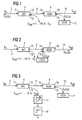
Fig. 2 zeigt den prinzipiellen Aufbau eines Moduls zur Überwachung
des abgehenden Zweiges der Übertragungsstrecke. In
Fig. 2 werden für die gleichen Teile wie in Fig. 1 die gleichen
Bezugszeichen verwendet. Durch Umkehr des Wellenlängenmultiplexers
8 wird erreicht, daß ein an dem Tor T5 eingekoppeltes
Signals SOTDR eine derartige Laufrichtung hat, dass der
abgehende Zweig der Übertragungsstrecke beziehungsweise der
Übertragungsstrecke 10 durch das Signal SOTDR überwacht wird.
Das Verhalten der Übertragungsstrecke 10 im Bezug auf das
übertragene Signal Sout wird dann in dem nächsten Überwachungsmodul
in der Übertragungsstrecke überwacht, wo ebenfalls
ein WIC vorgesehen ist, der dann einen Teil des übertragenen
Signals auskoppelt, welches Rückschlüsse über die
Übertragungscharakteristik der Übertragungsstrecke 10 zuläßt.Fig. 2 shows the basic structure of a module for monitoring the outgoing branch of the transmission link. In Fig. 2, the same reference numerals are used for the same parts as in Fig. 1. By reversing the
Fig. 3 zeigt den Modul von Fig. 1, wobei ein Photodetektor
und eine Logikschaltung 16 ergänzt sind, der Photodetektor 14
empfängt den ausgekoppelten Bruchteil SSUP des übertragenen
Signals SIN und gibt einen entsprechenden Messwert an die Logikschaltung
16 ab, die, beispielsweise über eine Schwellenwertbestimmung,
die Güte der Übertragungsstrecke beziehungsweise
einen Fehler in der Übertragungsstrecke feststellt und
ein elektrisches Signal beziehungsweise ein Alarmsignal abgibt.3 shows the module from FIG. 1, a photodetector and a
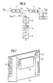
Fig. 4 ist eine weitere vorteilhafte Ausgestaltung des erfindungsgemäßen
Moduls, wobei ein Bandpassfilter 18 vor dem Photodetektor
14 vorgesehen ist, damit das zurückgestreute Signal
SOTDR nicht auf den Photodetektor 14 fällt und dort die
Messung verfälscht oder den Detektor übersättigt oder beschädigt.Fig. 4 is a further advantageous embodiment of the module according to the invention, wherein a
Die Ausführungsformen nach den Figuren 3 und 4 gelten in gleicher Weise für die Ausführungsbeispiele der Figuren 1 und 2.The embodiments according to FIGS. 3 and 4 apply in same way for the embodiments of Figures 1 and Second
Fig. 5 zeigt im Prinzip einen Aufbau eines Moduls, wenn das
OTDR-Signal in der ankommenden als auch in der abgehenden
Übertragungsstrecke eingekoppelt wird. Dazu sind in der Übertragungsstrecke
2 ein wellenlängenunabhängiger Koppler 30,
ein erster Wellenlängenmultiplexer 32 und ein zweiter Wellenlängenmultiplexer
34 vorgesehen. Wie bei den vorhergehenden
Ausführungsbeispielen wird ein Teil des Signales SIN, das an
dem Tor T1 des Kopplers 30 ankommt, an dem Tor T2 des Kopplers
30 als Überwachungssignal SSUP ausgekoppelt.Fig. 5 shows in principle a structure of a module when the OTDR signal is coupled in the incoming and outgoing transmission link. For this purpose, a wavelength-
Das Übertragungssignal wird von dem Tor T3 des Kopplers 30 an
das Tor T4 des ersten Wellenlängenmultiplexers 32 gegeben. Am
Tor T5 des Wellenlängenmultiplexers 32 wird das Proben- oder
OTDR-Signal SOTDR,ank eingekoppelt, welches den ankommenden Teil
der Überwachungsstrecke überwachen soll. An dem Tor T6 des
Wellenlängenmultiplexers 32 wird das übertragene Signal ausgegeben
und an dem Tor T7 in den zweiten Wellenlängenmultiplexer
34 eingegeben. Das übertragene Signal wird an dem Tor
T8 des Wellenlängenmultiplexers 34 als Signal SOUT ausgegeben.
An dem Tor T9 wird ein Probensignal SOTDR,abg eingekoppelt, welches
den abgehenden Teil der Übertragungsstrecke überwachen
soll. Der Koppler 30 und die Wellenlängenmultiplexer 32, 34
können wiederum in einem Modul zusammengefaßt werden.The transmission signal is sent from the gate T3 of the
Fig. 6 zeigt den prinzipiellen Aufbau eines Moduls zur Überwachung
von optischen Übertragungsstrecken, wobei die gleichen
Komponenten wie bei dem Ausführungsbeispiel von Fig. 1
verwendet werden. Abweichend von Fig. 1 ist hier jedoch der
Wellenmultiplexer 8 in Übertragungsrichtung, die durch die
Signale SIN und SOS dargestellt ist, vor dem Koppler 4 angeordnet.
Das in dem Wellenlängenmultiplexer 8 eingekoppelte
Probensignal SOTDR dient zur Überwachung des ankommenden Teiles
der Überwachungsstrecke. Dieses Ausführungsbeispiel der
Erfindung hat den weiteren Vorteil, daß die Filterung des
OTDR-Signals eingespart werden kann, weil dieses Signal vor
dem Koppler 4 ausgekoppelt wird und damit nicht auf den Detektor
gelangen kann.FIG. 6 shows the basic structure of a module for monitoring optical transmission links, the same components as in the exemplary embodiment from FIG. 1 being used. 1, however, the
Der Gesamtmodul kann aus diskreten Einzelbausteinen aufgebaut oder ein optisch integriertes Bauelement auf der Basis der SiO2, Si- oder InP- Technologie sein. Die Gesamtdämpfung des Signals zwischen dem Tor T1 und dem Tor T6 ist kleiner als 3 dB.The overall module can be constructed from discrete individual components or can be an optically integrated component based on SiO 2 , Si or InP technology. The total attenuation of the signal between gate T1 and gate T6 is less than 3 dB.
Fig. 7 zeigt einen Einschub mit einer Leiterplatte 20, auf
der der Überwachungsmodul 24, ein Paneel mit LWL-Kupplungen
22, insbesondere Kupplungen für die Kanäle Ch.1 bis Ch.4, einen
Ausgang 26 für einen elektrischen Alarm oder eine Spannungsversorgung
und eine Netzwerkschnittstelle 28 umfaßt. Die
eine Netzwerkschnittstelle ist insofern vorteilhaft, als über
diesen Einschub dann die Rechnerkapazität des Rechners genutzt
werden kann, in dem der Einschub montiert ist, um die
Auswertungen der in dem Überwachungsmodul gemessenen Signale
durchzuführen (LWL = Lichtwellenleiter).7 shows an insert with a printed
Obwohl in der vorhergehenden Beschreibung der Überwachungsmodul
so beschrieben ist, dass er einen wellenlängenunabhängigen
Koppler 4 beziehungsweise 30 in Kombination mit einem
oder mehreren Wellenlängenmultiplexern 8 beziehungsweise 32,
34 ist zu beachten, dass Überwachungsfunktionen dieser beiden
Bauteile separat voneinander genutzt werden können.Although in the previous description the monitoring module
is described as being a wavelength
Claims (14)
- Method for continuously monitoring an optical transmission path, wherein a fraction of a transmitted or arriving signal (SIN) is extracted independently of the wave length without interrupting the path to be monitored, wherein a test signal is introduced into the path to be monitored without interrupting the path to be monitored, wherein the test signal reflected by the transmission path is extracted without interrupting the path to be monitored, wherein the frequency of the test signal is chosen outside of the transmission band of the transmitted signal and wherein information on the quality of the transmission path or a defect in the transmission path is obtained based on a measurement of the extracted signal fraction (SSUP) as well as the reflected test signal.
- Method according to claim 1 wherein the test signal is an OTDR signal (SOTDR).
- Method according to claim 1 or 2 wherein the monitoring signal (SSUP), i.e. the extracted fraction of the transmitted signal (SIN) is filtered before the measurement in such a way that only signals that lie in the transmission band of the transmitted signal (SIN) are allowed to pass.
- Method according to one of the claims 1 to 3 wherein the measuring result is logically processed and wherein an alarm is triggered if a defect is detected.
- Method according to one of the claims 1 to 4, wherein the power of the extracted monitoring signal (SSUP) lies at 1 to 10% of the power of the transmitted signal (SIN).
- Method according to one of the preceding claims wherein the test signal is introduced into the transmission path of the transmitted signal as arriving or outgoing.
- Device for continuously monitoring an optical transmission path with a wavelength-multiplexer (8) for introducing a test signal (SOTDR), the frequency of which lies outside of the transmission band of the transmitted signal, into the transmission path without interrupting the path or for extracting a reflected signal from the transmission path without interrupting the path, respectively, with a wavelength-coupler (8) for extracting the reflected signal from the transmission path without interrupting the path, with a wavelength-independent coupling device (4) for extracting a fraction of a transmitted or arriving signal (SIN) in the form of a monitoring signal (SSUP), with a measurement device (14) for measuring the extracted monitoring signal (SSUP) and with devices (12, 16) that are respectively assigned to the wavelength-coupler (8) and the coupling device (4) and serve for evaluating the measured monitoring signal (SSUP) and the reflected signal such that information regarding the quality of the transmission path or a defect in the transmission path, respectively, is obtained.
- Device according to claim 7, wherein an OTD-reflectometer (12) is arranged downstream from the coupler (8).
- Device according to claim 7 or 8, wherein the measuring device (14) is a photodetector.
- Device according to one of the claims 7 to 9 wherein the device for evaluating the measured, extracted monitoring signal (SSUP) is a logic circuit (16) with alarm function.
- Device according to one of the claims 7 to 10 wherein a band pass filter (18) is arranged between the coupling device (4) and the measurement device (14).
- Device according to one of the claims 7 to 11 wherein two wavelength multiplexers (32), (34) are provided, with one wavelength multiplexer (32) being provided for introducing the test signal (SQTDR, ank) for the incoming section of the transmission path, and with the other wavelength multiplexer (34) being provided for introducing the test signal (SQTDR, abg) for the outgoing section of the transmission path.
- Device according to one of the claims 7 to 12 wherein the multiplexer (8) is arranged before the coupler (4) as seen in the direction of transmission.
- Device according to one of the claims 7 to 13 wherein the device that forms a module for monitoring optical transmission paths is arranged on a printed-circuit board or on a rack, respectively.
Applications Claiming Priority (3)
| Application Number | Priority Date | Filing Date | Title |
|---|---|---|---|
| DE19949401 | 1999-10-13 | ||
| DE19949401A DE19949401A1 (en) | 1999-10-13 | 1999-10-13 | Method and device for the continuous monitoring of an optical transmission link |
| PCT/DE2000/003618 WO2001028133A2 (en) | 1999-10-13 | 2000-10-13 | Method and device for continuously monitoring an optical transmission path |
Publications (2)
| Publication Number | Publication Date |
|---|---|
| EP1224754A2 EP1224754A2 (en) | 2002-07-24 |
| EP1224754B1 true EP1224754B1 (en) | 2003-07-23 |
Family
ID=7925519
Family Applications (1)
| Application Number | Title | Priority Date | Filing Date |
|---|---|---|---|
| EP00983003A Expired - Fee Related EP1224754B1 (en) | 1999-10-13 | 2000-10-13 | Method and device for continuously monitoring an optical transmission path |
Country Status (6)
| Country | Link |
|---|---|
| US (1) | US6842236B1 (en) |
| EP (1) | EP1224754B1 (en) |
| JP (1) | JP2003511964A (en) |
| CA (1) | CA2388059A1 (en) |
| DE (2) | DE19949401A1 (en) |
| WO (1) | WO2001028133A2 (en) |
Families Citing this family (9)
| Publication number | Priority date | Publication date | Assignee | Title |
|---|---|---|---|---|
| US20020131106A1 (en) | 2001-03-16 | 2002-09-19 | Peter Snawerdt | Secure wave-division multiplexing telecommunications system and method |
| US7542674B1 (en) | 2001-05-24 | 2009-06-02 | Cisco Technology, Inc. | Optical link performance monitoring |
| AU2002318180A1 (en) | 2001-07-09 | 2003-01-29 | Oyster Optics, Inc. | Fiber optic telecommunications card with security detection |
| US20050123293A1 (en) * | 2002-07-23 | 2005-06-09 | Fujitsu Limited | Optical transmission method and system |
| JP3808824B2 (en) * | 2002-11-20 | 2006-08-16 | 株式会社日立製作所 | Information transmission system and information transmission method |
| GB0514680D0 (en) * | 2005-07-16 | 2005-08-24 | Tyco Electronics Raychem Nv | PCB optical network monitor |
| WO2014038036A1 (en) * | 2012-09-06 | 2014-03-13 | ソフトバンクテレコム株式会社 | Wavelength monitoring system and wavelength monitoring method |
| CN105116287B (en) * | 2015-08-24 | 2021-05-25 | 江苏省电力公司南京供电公司 | High-voltage cable line fault on-line positioning system and positioning method thereof |
| KR20180098718A (en) * | 2017-02-27 | 2018-09-05 | (주)지씨아이 | Optical time domain reflectometer for divided optical fiber monitering on optical termination box |
Family Cites Families (6)
| Publication number | Priority date | Publication date | Assignee | Title |
|---|---|---|---|---|
| GB9604322D0 (en) * | 1996-02-29 | 1996-05-01 | Stc Submarine Systems Ltd | EOTDR three wavelength signalling |
| US6385203B2 (en) * | 1996-03-29 | 2002-05-07 | Cisco Technology, Inc. | Communication server apparatus and method |
| US5790285A (en) | 1996-05-21 | 1998-08-04 | Lucent Technologies Inc. | Lightwave communication monitoring system |
| EP0841552B1 (en) | 1997-01-16 | 1999-04-07 | Hewlett-Packard Company | Optical time domain reflectometer for measurement in optical networks with currently applied traffic signals |
| DE29819353U1 (en) | 1998-10-30 | 1999-01-07 | Lancier Masch Peter | Optical fiber monitoring device |
| US6633642B1 (en) * | 1999-05-11 | 2003-10-14 | Fluke Corporation | Balance network directional coupler system and method |
-
1999
- 1999-10-13 DE DE19949401A patent/DE19949401A1/en not_active Withdrawn
-
2000
- 2000-10-13 US US10/110,520 patent/US6842236B1/en not_active Expired - Fee Related
- 2000-10-13 JP JP2001530237A patent/JP2003511964A/en active Pending
- 2000-10-13 EP EP00983003A patent/EP1224754B1/en not_active Expired - Fee Related
- 2000-10-13 DE DE50003032T patent/DE50003032D1/en not_active Expired - Fee Related
- 2000-10-13 WO PCT/DE2000/003618 patent/WO2001028133A2/en active IP Right Grant
- 2000-10-13 CA CA002388059A patent/CA2388059A1/en not_active Abandoned
Also Published As
| Publication number | Publication date |
|---|---|
| EP1224754A2 (en) | 2002-07-24 |
| DE50003032D1 (en) | 2003-08-28 |
| DE19949401A1 (en) | 2001-04-19 |
| WO2001028133A2 (en) | 2001-04-19 |
| CA2388059A1 (en) | 2001-04-19 |
| WO2001028133A3 (en) | 2001-06-07 |
| JP2003511964A (en) | 2003-03-25 |
| US6842236B1 (en) | 2005-01-11 |
Similar Documents
| Publication | Publication Date | Title |
|---|---|---|
| DE69736560T2 (en) | MONITORING SYSTEM USING AN OPTICAL BACK-UP SIGNAL AS A TEST SIGNAL | |
| DE69736201T2 (en) | Optical time domain reflectometer for monitoring the operation of optical cables | |
| DE69736856T2 (en) | Monitoring nonlinear effects in an optical transmission system | |
| EP1796295B1 (en) | Method for detection and location of faults on an optical transmission path and optical transmission system | |
| DE69737269T2 (en) | LOCKABLE FIBER OPTIC HIGH PERFORMANCE SYSTEM WITH TIME RANGE REFLECTOMETER | |
| DE69634611T2 (en) | SELF-HEALING NETWORK | |
| DE60226190T2 (en) | Method and device for measuring and determining the optical signal-to-noise ratio in optical networks | |
| DE602005004787T2 (en) | An optical transmitter-receiver module for monitoring an optical fiber and method for providing the monitoring data of the optical fiber | |
| DE10216279A1 (en) | Method for the detection of a control signal in an optical transmission system | |
| EP1224754B1 (en) | Method and device for continuously monitoring an optical transmission path | |
| EP3633877B1 (en) | Method for detecting discontinuities in an optical channel, especially in a fibre optic line | |
| DE69823609T2 (en) | Monitoring the optical signal power with a signature bit pattern in WDM systems | |
| DE102007015628B4 (en) | Method and device for monitoring a data transmission path, in particular an optical bidirectional data transmission path | |
| WO2000003504A1 (en) | Method and device for executing control and monitoring measurements in optical transmission paths | |
| DE60127060T2 (en) | Measurement of the polarization-dependent property of optical units | |
| CH650625A5 (en) | TROUBLESHOOTING EQUIPMENT FOR A DUPLEX TRANSMISSION LINE WITH INTERMEDIATE AMPLIFIERS. | |
| EP0111582A1 (en) | Fault locating arrangement for an optical fibre cable link | |
| CH652543A5 (en) | METHOD AND DEVICE FOR MONITORING A TRANSMISSION SYSTEM. | |
| EP1063793B1 (en) | Optical data signal quality measurement method | |
| DE60214646T2 (en) | Method and device for monitoring an optical transmission path | |
| DE10360788A1 (en) | Optical communication network and component for it | |
| DE69829799T2 (en) | Measurement of eye opening of optical signals by optical scanning | |
| DE19930975A1 (en) | Cross-talk measurement of profit channel in optic transmission system | |
| DE60205663T2 (en) | METHOD AND DEVICE FOR WDM SIGNAL TRANSMISSION THROUGH AN OPTICAL FIBER USING THE RAMANIUM GAIN | |
| EP0599155B1 (en) | Optical transmission system using optical amplifiers and device for testing the transmission path |
Legal Events
| Date | Code | Title | Description |
|---|---|---|---|
| PUAI | Public reference made under article 153(3) epc to a published international application that has entered the european phase |
Free format text: ORIGINAL CODE: 0009012 |
|
| 17P | Request for examination filed |
Effective date: 20020513 |
|
| AK | Designated contracting states |
Kind code of ref document: A2 Designated state(s): AT BE CH CY DE DK ES FI FR GB GR IE IT LI LU MC NL PT SE |
|
| GRAH | Despatch of communication of intention to grant a patent |
Free format text: ORIGINAL CODE: EPIDOS IGRA |
|
| RAP1 | Party data changed (applicant data changed or rights of an application transferred) |
Owner name: CORNING INCORPORATED |
|
| GRAH | Despatch of communication of intention to grant a patent |
Free format text: ORIGINAL CODE: EPIDOS IGRA |
|
| GRAA | (expected) grant |
Free format text: ORIGINAL CODE: 0009210 |
|
| AK | Designated contracting states |
Designated state(s): DE FR GB IT |
|
| PG25 | Lapsed in a contracting state [announced via postgrant information from national office to epo] |
Ref country code: IT Free format text: LAPSE BECAUSE OF FAILURE TO SUBMIT A TRANSLATION OF THE DESCRIPTION OR TO PAY THE FEE WITHIN THE PRE;WARNING: LAPSES OF ITALIAN PATENTS WITH EFFECTIVE DATE BEFORE 2007 MAY HAVE OCCURRED AT ANY TIME BEFORE 2007. THE CORRECT EFFECTIVE DATE MAY BE DIFFERENT FROM THE ONE RECORDED.SCRIBED TIME-LIMIT Effective date: 20030723 |
|
| REG | Reference to a national code |
Ref country code: GB Ref legal event code: FG4D Free format text: NOT ENGLISH |
|
| REG | Reference to a national code |
Ref country code: IE Ref legal event code: FG4D Free format text: GERMAN |
|
| REF | Corresponds to: |
Ref document number: 50003032 Country of ref document: DE Date of ref document: 20030828 Kind code of ref document: P |
|
| GBT | Gb: translation of ep patent filed (gb section 77(6)(a)/1977) |
Effective date: 20031119 |
|
| REG | Reference to a national code |
Ref country code: IE Ref legal event code: FD4D |
|
| ET | Fr: translation filed | ||
| PLBE | No opposition filed within time limit |
Free format text: ORIGINAL CODE: 0009261 |
|
| STAA | Information on the status of an ep patent application or granted ep patent |
Free format text: STATUS: NO OPPOSITION FILED WITHIN TIME LIMIT |
|
| 26N | No opposition filed |
Effective date: 20040426 |
|
| PGFP | Annual fee paid to national office [announced via postgrant information from national office to epo] |
Ref country code: GB Payment date: 20040915 Year of fee payment: 5 |
|
| PGFP | Annual fee paid to national office [announced via postgrant information from national office to epo] |
Ref country code: FR Payment date: 20041004 Year of fee payment: 5 |
|
| PGFP | Annual fee paid to national office [announced via postgrant information from national office to epo] |
Ref country code: DE Payment date: 20041029 Year of fee payment: 5 |
|
| PG25 | Lapsed in a contracting state [announced via postgrant information from national office to epo] |
Ref country code: GB Free format text: LAPSE BECAUSE OF NON-PAYMENT OF DUE FEES Effective date: 20051013 |
|
| PG25 | Lapsed in a contracting state [announced via postgrant information from national office to epo] |
Ref country code: DE Free format text: LAPSE BECAUSE OF NON-PAYMENT OF DUE FEES Effective date: 20060503 |
|
| GBPC | Gb: european patent ceased through non-payment of renewal fee |
Effective date: 20051013 |
|
| PG25 | Lapsed in a contracting state [announced via postgrant information from national office to epo] |
Ref country code: FR Free format text: LAPSE BECAUSE OF NON-PAYMENT OF DUE FEES Effective date: 20060630 |
|
| REG | Reference to a national code |
Ref country code: FR Ref legal event code: ST Effective date: 20060630 |