EP1222777B1 - Multiple wireless communication protocol methods and apparatuses - Google Patents
Multiple wireless communication protocol methods and apparatuses Download PDFInfo
- Publication number
- EP1222777B1 EP1222777B1 EP00967090.2A EP00967090A EP1222777B1 EP 1222777 B1 EP1222777 B1 EP 1222777B1 EP 00967090 A EP00967090 A EP 00967090A EP 1222777 B1 EP1222777 B1 EP 1222777B1
- Authority
- EP
- European Patent Office
- Prior art keywords
- devices
- interference
- network
- network devices
- accordance
- Prior art date
- Legal status (The legal status is an assumption and is not a legal conclusion. Google has not performed a legal analysis and makes no representation as to the accuracy of the status listed.)
- Expired - Lifetime
Links
Images


Classifications
-
- H—ELECTRICITY
- H04—ELECTRIC COMMUNICATION TECHNIQUE
- H04W—WIRELESS COMMUNICATION NETWORKS
- H04W88/00—Devices specially adapted for wireless communication networks, e.g. terminals, base stations or access point devices
- H04W88/02—Terminal devices
- H04W88/06—Terminal devices adapted for operation in multiple networks or having at least two operational modes, e.g. multi-mode terminals
-
- H—ELECTRICITY
- H04—ELECTRIC COMMUNICATION TECHNIQUE
- H04L—TRANSMISSION OF DIGITAL INFORMATION, e.g. TELEGRAPHIC COMMUNICATION
- H04L12/00—Data switching networks
- H04L12/66—Arrangements for connecting between networks having differing types of switching systems, e.g. gateways
-
- H—ELECTRICITY
- H04—ELECTRIC COMMUNICATION TECHNIQUE
- H04L—TRANSMISSION OF DIGITAL INFORMATION, e.g. TELEGRAPHIC COMMUNICATION
- H04L9/00—Cryptographic mechanisms or cryptographic arrangements for secret or secure communications; Network security protocols
- H04L9/40—Network security protocols
-
- H—ELECTRICITY
- H04—ELECTRIC COMMUNICATION TECHNIQUE
- H04L—TRANSMISSION OF DIGITAL INFORMATION, e.g. TELEGRAPHIC COMMUNICATION
- H04L65/00—Network arrangements, protocols or services for supporting real-time applications in data packet communication
- H04L65/1066—Session management
- H04L65/1101—Session protocols
-
- H—ELECTRICITY
- H04—ELECTRIC COMMUNICATION TECHNIQUE
- H04L—TRANSMISSION OF DIGITAL INFORMATION, e.g. TELEGRAPHIC COMMUNICATION
- H04L69/00—Network arrangements, protocols or services independent of the application payload and not provided for in the other groups of this subclass
- H04L69/08—Protocols for interworking; Protocol conversion
-
- H—ELECTRICITY
- H04—ELECTRIC COMMUNICATION TECHNIQUE
- H04L—TRANSMISSION OF DIGITAL INFORMATION, e.g. TELEGRAPHIC COMMUNICATION
- H04L69/00—Network arrangements, protocols or services independent of the application payload and not provided for in the other groups of this subclass
- H04L69/18—Multiprotocol handlers, e.g. single devices capable of handling multiple protocols
-
- H—ELECTRICITY
- H04—ELECTRIC COMMUNICATION TECHNIQUE
- H04W—WIRELESS COMMUNICATION NETWORKS
- H04W16/00—Network planning, e.g. coverage or traffic planning tools; Network deployment, e.g. resource partitioning or cells structures
- H04W16/14—Spectrum sharing arrangements between different networks
Definitions
- the present invention relates to the field of wireless communication. More specifically, the present invention relates to the problem of concurrent wireless communication with multiple communication partners of different wireless communication protocols.
- wireless communication Once confined to the privileged, wireless voice communication have become affordable and available to the masses.
- Bluetooth technology A leading candidate to accomplish the former is commonly known to those skilled in the art as the Bluetooth technology or Bluetooth protocol.
- Examples of technology to accomplish the later include the different variants of the IEEE 802.11 Standard published by the Institute of Electrical and Electronic Engineers, 802.11 (Frequency Hoping, Direct Sequence), 802.11a, 802.1b, as well as Home RF, also known as Shared Wireless Access Protocol (SWAP) to those skilled in the art.
- SWAP Shared Wireless Access Protocol
- One such applications is having a notebook computer being able to communicate with peripheral devices such as a phone, a printer, a scanner and the like, in accordance with the Bluetooth protocol; and with other computing devices, such as other peer computers or servers, communication devices, such as modems or adapters, and networking devices, such as gateways, routers, switches and the like, in accordance with one of the 802.11 protocols or Home RF.
- the need cannot be met by simply providing the device with multiple transmitters, one for each protocol. The reason is because if multiple ones of these transmitters were to transmit at the same time. The transmitters are going to interfere with each other, resulting in corruption and/or loss of data, as well as degradation in performance.
- the present invention substantially address this need in a very efficient and low cost manner. This and other advantages of the present invention will be readily apparent from the description to follow.
- WO99/2912 discloses a mobile radio communication terminal having two transceivers that are respectively adapted to communicate with a first and second radio communication network.
- apparatus comprising:
- wireless device 100 is provided with wireless transceivers 102a and 102b to transmit and receive signals wirelessly in accordance with a first and a second wireless communication protocol, to enable device 100 to be communicatively coupled to devices 104a and devices 104b of wireless networks 108a and 108b respectively.
- Wireless device 100 further includes controller managers 106a and 106b to control the operation of wireless transceivers 102a and 102b respectively.
- controller managers 106a and 106b control transmits and receives by wireless transceivers 102a and 102b, in a coordinated manner, in accordance with the present invention, to allow wireless device 100 to operate with devices 104a and devices 104b of wireless network 108a and 108b in accordance with the respective wireless communication protocols at the same time.
- controller managers 106a and 106b control transmits and receives by wireless transceivers 102a and 102b (hereinafter, simply transceivers), in a coordinated manner. More specifically, in this embodiment, controller managers 106a and 106b control transceivers 102a and 102b to alternate between transmits by one of the two transceivers and receives by both of the two transceivers.
- Figure 2 illustrates a period of operation in accordance with this embodiment.
- control manager 106a controls transceiver 102a to perform transmit of signals to devices 104a of wireless network 108a (hereinafter, simply network) in accordance with the first wireless communication protocol (hereinafter, simply protocol), while control manager 106b controls transceiver 102b to neither perform transmit nor receive of signals to and from devices 104b of network 108b.
- simply protocol the first wireless communication protocol
- control manager 106b controls transceiver 102b to neither perform transmit nor receive of signals to and from devices 104b of network 108b.
- time period T3 for duration t3, the reverse is performed.
- Control manager 106b controls transceiver 102b to perform transmit of signals to devices 104b of network 108b in accordance with the second protocol
- control manager 106a controls transceiver 102a to neither perform transmit nor receive of signals to and from devices 104a of network 108a.
- control managers 106a and 106b control both transceivers 102a and 102b to perform receive of signals from devices 104a and 104b of network 108a and 108b in accordance with the respective protocols respectively.
- devices 104a are able to receive in time period T1, and transmit when there are packets to transmit, but otherwise receive, in time periods T2-T4.
- devices 104b are able to receive in time period T3, and transmit when there are packets to transmit, but otherwise receive, in time periods T1-T2 and T4.
- wireless device 100 is able to operate with devices 104a and 104b of networks 108a and 108b in two wireless protocols at the same time.
- time periods T1-T4 may or may not be equal in duration. That is, numerically t1-t4 may or may not be equal.
- duration t1-t4 of time periods T1-T4 are dynamically and adaptively set.
- duration t1-t4 of time periods T1-T4 are adaptively set based at least in part of transmit and receive workloads of networks 108a and 108b.
- transceivers 102 a and 102b as well as controller managers 106a and 106b are otherwise intended to represent a broad range of these elements known in the art. Accordingly, except for the teachings of the present invention, which will be further described below, transceivers 102a and 102b and controller managers 106a and 106b will not be otherwise further described.
- Wireless device 100 is intended to represent a wide range of devices that can benefit from having the ability to wirelessly operate with other wireless devices in two or more wireless communication protocols at the same time.
- Examples of device 100 include but not limited to computers of various form factors, such as desktop, notebook, palm size and so forth, controller devices (i.e. master devices) to manage and control the operation of networks 108a and 108b, and gateway devices to facilitate communication between devices 104a and devices 104b.
- devices 104a and 104b are intended to represent a broad range of devices that can benefit from being able to communicate wirelessly.
- devices 104a include but not limited to phones, video cameras, speakers, modems, printers and scanners equipped to wireless communicate in accordance with the Bluetooth protocol.
- devices 104b include clients and servers, as well as gateways, modems, hubs, routers, and switches equipped to wireless communicate in accordance with a selected variant of the IEEE 802.11 protocols or Home RF.
- Fig. 1 For ease of understanding, only two groups of devices 104a and 104b, communicating in accordance with the first and second wireless communication protocols are shown in Fig. 1 . However, from the description to follow, it will be readily apparent to those skilled in the art, the present invention may be practiced with more than two transceivers (as long as the transceivers are likewise coordinated).
- each controller manager 106a/106b of wireless device 100 is endowed with a state machine 300a/300b to complementarily assist the controller manager 106a/106b to control its transceiver 102a/102b in the above described coordinated manner.
- each state machine 300a/300b in addition to idle state 410, has four operating states 412-418 (TX, RX1, NOP, and RX2) to output a signal 304a/304b denoting a selected one of a transmit (TX) operation, a receive (RX) operation and no-op (NOP) for its controller manager 106a/106b.
- TX transmit
- RX receive
- NOP no-op
- each state machine 300a/300b Upon power-on or reset, each state machine 300a/300b either transitions from idle state 410 to TX state 412 or NOP state 416, depending on the state of configuration (config) signal 302a/302b.
- One state machine, e.g. 300a is configured to transition from idle state 410 to TX state 412, while the other state machine, e.g. 300b, is configured to transition from idle state 410 to TX state 412.
- Config signal 302a/302b may be set e.g. via a jumper or other equivalent means, as well as through software.
- state machine 300a/300b While in TX state 412, state machine 300a/300b remains in the state for duration ts1, outputting signal 304a/304b denoting TX operation for its controller manager 1026a/106b.
- t1 and t3 may take on different values
- one state machine, e.g. 300a is configured with ts1 set to t1
- the other state machine, e.g. 300b is configured with ts1 set to t3.
- Ts1 may be selectively set in any one of a number of techniques known in the art, e.g. through separate registers or multiplexing circuitry.
- state machine 300a/300b transitions from TX state 412 to RX1 state 414.
- state machine 300a/300b While in RX1 state 414, state machine 300a/300b remains in the state for duration ts2, outputting signal 304a/304b denoting RX operation for its controller manager 106a/106b.
- t2 and t4 may take on different values
- one state machine, e.g. 300a is configured with ts2 set to t2
- the other state machine, e.g. 300b is configured with ts2 set to t4.
- Ts2 may likewise be selectively set in any one of a number of techniques known in the art.
- state machine 300a/300b While in NOP state 416, state machine 300a/300b remains in the state for duration ts3, outputting signal 304a/304b denoting NOP for its controller manager 106a/106b.
- t1 and t3 may take on different values
- one state machine, e.g. 300a is configured with ts3 set to t3
- the other state machine, e.g. 300b is configured with ts3 set to t1.
- Ts3 may likewise be selectively set in any one of a number of techniques known in the art.
- state machine 300a/300b While in RX2 state 418, state machine 300a/300b remains in the state for duration ts4, outputting signal 304a/304b denoting RX operation for its controller manager 106a/106b.
- t2 and t4 may take on different values
- one state machine, e.g. 300a is configured with ts4 set to t4
- the other state machine, e.g. 300b is configured with ts4 set to t2.
- Ts4 may likewise be selectively set in any one of a number of techniques known in the art.
- state machine 300a/300b continues operation as described earlier.
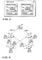
- FIG. 5 and 6 wherein a block diagram and a state diagram illustrating wireless device 100 of Fig. 1 in further detail, in accordance with another embodiment, are shown.
- each controller manager 106a/106b of wireless device 100 instead of having each controller manager 106a/106b of wireless device 100 be endowed with a state machine to complementarily assist the controller manager 106a/106b to control its transceiver 102a/102b in the above described coordinated manner, wireless device 100 is endowed with a single state machine 500 to assist both controller managers 106a and 106b.
- state machine 500 in addition to idle state 610, has four operating states 612-618 (S1 - S4) to output a pair of signals 504a-504b denoting a selected combination of operations, TX with NOP, both RX, and NOP with TX for controller managers 106a and 106b.
- state machine 500 Upon power-on or reset, state machine 500 transitions from idle state 610 to S1 state 612. While in S1 state 612, state machine 500 remains in the state for duration ts1, outputting signal 504a-504b denoting TX and NOP for controller managers 106a and 106b. Ts1 is set to t1. Upon expiration of ts1, state machine 500 transitions from S1 state 612 to S2 state 614. While in S2 state 614, state machine 500 remains in the state for duration ts2, outputting signal 504a-504b denoting RX for both controller managers 106a and 106b. Ts2 is set to t2. Upon expiration of ts2, state machine 500 transitions from S2 state 614 to S3 state 616.
- state machine 500 While in S3 state 616, state machine 500 remains in the state for duration ts3, outputting signal 504a-504b denoting NOP and TX for controller managers 106a and 106b. Ts3 is set to t3. Upon expiration of ts3, state machine 500 transitions from S3 state 616 to S4 state 618. While in S4 state 618, state machine 500 remains in the state for duration ts4, outputting signal 504a-504b denoting RX for both controller managers 106a and 106b. Ts4 is set to t4. Upon expiration of ts4, state machine 500 transitions from S4 state 618 to S1 state 612.
- state machine 500 continues operation as described earlier.
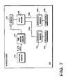
- FIG. 7 a block diagram illustrating wireless device 100 of Fig. 1 in further detail, in accordance with yet another embodiment, is shown.
- wireless device 100 in addition to having wireless device 100 be endowed with a single state machine 700 to assist both controller managers 106a and 106b as described earlier (with signals 708a-708a denoting TX-NOP, RX-RX or NOP-TX), wireless device 100 is further endowed with register 702, time sharing manager 704, and workload monitor 706 operatively coupled to each other and state machine 700 as shown.
- Register 702 stores t1-t4 for state machine 700.
- Time sharing manager 704 dynamically adjusts t1-t4 to enable state machine 700 be able to adaptively assist controller managers 106a and 106b in controlling transceivers 102a and 102b. For the illustrated embodiment, time sharing manager 704 dynamically adjusts t1-t4 based at least in part on transmit and receive workloads of networks 108a and 108b. Transmit and receive workloads are monitored by workload monitor 706 and provided to time sharing manager 704.
- Register 702 may be constituted with any storage circuitry known in the art.
- Time sharing manager 704 and workload monitor 706 may be implemented with any combinatorial logic or in software.
- first protocol of wireless devices 104a of network 108a is assumed to be a frequency hopping protocol as shown, i.e. wireless devices 104a hop from frequency to frequency in accordance with a pseudo random pattern to transmit signals.
- second protocol of wireless devices 104b of network 108b is assumed to be a constant frequency protocol (although in alternate embodiments, it may also be a frequency hopping protocol).
- at least one of the frequencies of the first protocol is the same frequency of the second protocol.
- frequency interference is shown to occur at the 7 th and 14 th hop (f 7 and f 14 ). That is, in accordance with the pseudo random pattern, in each of these two hops, devices 104a transmit in the same frequency employed by devices 104b.
- An example of a frequency hopping protocol is the Bluetooth protocol, and an example of a protocol having an interfering frequency with Bluetooth is the 802.11 protocol.
- the interference pattern is dictated by the intersection of the pseudo random pattern followed by the frequency hopping devices 104a and the frequency employed by devices 104b. ]
- wireless device 100 coordinates the operation of devices 104a and 104b to proactively reduce actual occurrence of interference. More specifically, for the illustrated embodiments, either devices 104a or devices 104b are selected to be the "dominant" devices. The non-selected devices are considered to be the dominated devices. The dominated devices are notified, from time to time, to suspend operation to pro-actively avoid interference with the dominant devices, allowing the dominant devices to continue to operate without interference. As result, the time consuming collision detection, back off and retries are substantially reduced, and experience has shown that the overall operating efficiencies of both networks improve, the dominated network as well as the dominant network.
- Fig. 8a illustrates a period of operation when devices 104a, the frequency hopping devices, are selected to be the dominant devices
- Fig. 8b illustrates a period of operation when devices 104b are selected to be the dominant devices. That is, under Fig. 8a , devices 104b, upon informed, will temporarily suspend operation to proactively avoid interference, whereas under Fig. 8b , devices 104a, upon informed, will temporarily suspend operation to proactively avoid interference.
- wireless device 100 basically operates as earlier described. Except wireless device 100 assumes the additional responsibilities of determining the pseudo random frequency hopping pattern of devices 104a (in one embodiment, including the interfering frequency), selecting either devices 104a or 104b to be the dominated devices, predicting the occurrence of interference, and preemptively notifying the dominated devices to suspend operation to avoid interference (in one embodiment, conditionally suspending operation).
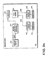
- wireless device 100 is basically the embodiment earlier described referencing Fig. 7 , except wireless device 100 is further provided with network management application (or network manager) 904 to proactively managing network devices 104a and 104b to reduce actual occurrence of interference.
- Network manager 904 also subsumes the earlier described responsibilities of time sharing manager 704, i.e. monitoring the workloads of the two protocols, and adaptively setting the values of t1-t4 for time period T1-T4.
- network manager 904 monitors the operation of devices 104a and 104b for an observation period, and determines the pseudo random frequency hopping pattern followed by devices 104a (and in one embodiment, the interfering frequency with devices 104b ), 912. This may be accomplished using any one of a number of techniques known in the art.
- network manager 904 selects either devices 104a or devices 104b to be the dominant devices, 914.
- network manager 904 makes the selection in accordance with configuration information programmed in configuration register 902. In alternate embodiments, other configuration registers, or other techniques known in the art, such as jumpers, may also be employed to assist network manager 904 in making the selection.
- network manager 904 predicts when interference will occur, using the determined pseudo random pattern and interference frequency, 916. Whenever, an interference is to occur, network manager 904 preemptively notifies the dominated devices to suspend operation accordingly, thereby allowing the dominant devices to operate without interference, 918. [In one embodiment, if the dominated devices are devices 104a, the notification includes the interfering frequency, and the suspension is conditional, only if the predicted frequency is indeed the interfering frequency.] The process continues, as long as there are wireless devices of both types 104a and 104b operating.
- network manager 904 repeats the calibration periodically. In yet another embodiment, network manager 904 monitors actual interference between devices 104a and 104b, and tracks the mean time between interference. Network manager 904 repeats the calibration, whenever the tracked mean time between interference drops below certain given performance level.
- network manager 904 may make the selection of the dominated devices in a dynamic and individualized manner, when an interference is predicted to occur. That is, different device or devices 104a and 104b are dynamically and individually selected for different predictions of interference. Such dynamic, individualized manner of selection may also be made in view of the workloads of the two protocols.
- the above described improved manner of operation may be practiced with minimal or no change to devices 104,a and 104a, as virtually all network devices are capable of temporarily suspending operation responsive to a request.
- the conditional performance may be effectuated through addition of simple frequency testing combinatorial logic.
- first protocol of wireless devices 104a of network 108a is assumed to be a frequency hopping protocol
- second protocol of wireless devices 104b of network 108b is assumed to be a constant frequency protocol (although it may also be a frequency hopping protocol).
- wireless device 100 coordinates the operation of devices 104a and 104b to proactively reduce actual occurrence of interference. More specifically, under this embodiment, devices 104a and 104b are correspondingly notified of the filtering to be employed to correspondingly cancel the respective interfering signals, and when to apply the filtering.
- the filtering to be employed is a notch filter inversely formed in accordance with the other devices' signal.
- both devices 104a and 104b apply the corresponding required filtering to correspondingly cancel the respective interfering signals.
- the basic operations of wireless device 100 remain substantially unchanged, except, wireless device 100 assumes the additional responsibilities of determining the pseudo random frequency hopping pattern of devices 104a, the interfering frequency, the corresponding faltering to be employed to cancel the respective interfering signals, and preemptively notifying devices 104a and 104b of the determined filtering as well as when to apply them.
- wireless device 100 is basically the embodiment earlier described referencing Fig. 9a . That is, wireless device 100 is also additionally provided with network manager 1104, except the additional responsibilities assumed by network manager 1104 to proactively reduce interference, are slightly different.
- network manager 1104 monitors the operation of devices 104a and 104b for an observation period, and determines the pseudo random frequency hopping pattern followed by devices 104a, and the interfering frequency with devices 104b, 1112. This again may be accomplished using any one of a number of techniques known in the art.
- network manager 1104 determines the corresponding filtering to be employed by devices 104a and 104b to correspondingly cancel their respective interfering signals of " the other devices ", and provides the determined information to devices 104a and 104b, 1114.
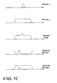
- the corresponding filtering to be employed are notched filters inversely constructed in accordance with the other devices' signals (see Fig. 12 ).
- devices 104a are to apply a notch filter, inversely formed in accordance with transmit signals of devices 104b, whereas, devices 104b are to apply a notch filter, inversely formed in accordance with transmit signals of devices 104a.
- Notch filters in general are known in the art, and will not be further described.
- network manager 1104 predicts when interference will occur, using the determined pseudo random pattern and interference frequency, 1116. Whenever, an interference is to occur, network manager 1104 preemptively notifies devices 104a and 104b to correspondingly apply their corresponding filtering, thereby allowing both devices 104a and 104b to operate without interference, 1118. The process continues, as long as there are wireless devices of both types 104a and 104b operating. [Likewise, the application of filtering by devices 104a may also be conditionally performed, only if the frequency is indeed the same as the interfering frequency.]
- network manager 1104 repeats the calibration periodically.
- network manager 1104 monitors actual interference between devices 104a and 104b, and tracks the mean time between interference.
- Network manager 1104 repeats the calibration, whenever the tracked mean time between interference drops below certain given performance level.
- devices 104a and 104a may also be practiced with minimal change to devices 104a and 104a, by equipping both types of network devices with the ability to responsively apply notch filtering.
- devices 104a may be additionally provided with simple combinatorial logic to effectuate the conditional application of notch filtering.
- wireless device 100 is communicatively coupled to devices 104a and devices 104b of wireless networks 108a and 108b respectively.
- Wireless device 100 performs transmits and receives of the two protocols, in a coordinated manner, to allow wireless device 100 to operate with devices 104a and devices 104b of wireless network 108a and 108b in accordance with the respective protocols at the same time.
- unlike the embodiment of Fig. 1 wireless device 100 is communicatively coupled to devices 104a and devices 104b of wireless networks 108a and 108b respectively.
- Wireless device 100 performs transmits and receives of the two protocols, in a coordinated manner, to allow wireless device 100 to operate with devices 104a and devices 104b of wireless network 108a and 108b in accordance with the respective protocols at the same time.
- wireless device 100 is provided with a single wireless transceiver 1302, which includes joint signal transmit / receive section 1303, and a number of transmit and receive signals up / down conversion sections 1205 sharing joint signal transmit / receive section 1303 .
- Wireless device 100 further includes controller / signal processing ( C / SP ) section 1306 to process data for transmission by wireless transceiver 1302, to process signals received by wireless transceiver 1302, and to control the data / signal processing operations as well as the operation of wireless transceiver 1302.
- C / SP controller / signal processing
- wireless device 100 is endowed with a network manager equipped with the capabilities earlier described referencing Figs. 8a-8b and 9a-9b. In other embodiments, wireless device 100 is endowed with a network manager equipped with the capabilities earlier described referencing Figs, 10 and 11a - 11b .
Landscapes
- Engineering & Computer Science (AREA)
- Computer Networks & Wireless Communication (AREA)
- Signal Processing (AREA)
- Computer Security & Cryptography (AREA)
- Mobile Radio Communication Systems (AREA)
- Small-Scale Networks (AREA)
- Communication Control (AREA)
Description
- The present invention relates to the field of wireless communication. More specifically, the present invention relates to the problem of concurrent wireless communication with multiple communication partners of different wireless communication protocols.
- Advances in microprocessor and communication technology have led to the increase in popularity of wireless communication. Once confined to the privileged, wireless voice communication have become affordable and available to the masses. Today, various efforts are under way to apply wireless communication to replace attachment cables used for attaching peripheral devices, such as printers, scanners and the like, as well as networking cables used for connecting clients, servers and the like. A leading candidate to accomplish the former is commonly known to those skilled in the art as the Bluetooth technology or Bluetooth protocol. Examples of technology to accomplish the later include the different variants of the IEEE 802.11 Standard published by the Institute of Electrical and Electronic Engineers, 802.11 (Frequency Hoping, Direct Sequence), 802.11a, 802.1b, as well as Home RF, also known as Shared Wireless Access Protocol (SWAP) to those skilled in the art.
- A need has emerged in a number of applications that it is desirable for a device to be able to operate "concurrently" in multiple wireless protocols. One such applications is having a notebook computer being able to communicate with peripheral devices such as a phone, a printer, a scanner and the like, in accordance with the Bluetooth protocol; and with other computing devices, such as other peer computers or servers, communication devices, such as modems or adapters, and networking devices, such as gateways, routers, switches and the like, in accordance with one of the 802.11 protocols or Home RF.
- However, the need cannot be met by simply providing the device with multiple transmitters, one for each protocol. The reason is because if multiple ones of these transmitters were to transmit at the same time. The transmitters are going to interfere with each other, resulting in corruption and/or loss of data, as well as degradation in performance.
- As will be described in more detail below, the present invention substantially address this need in a very efficient and low cost manner. This and other advantages of the present invention will be readily apparent from the description to follow.
-
WO99/2912 - According to one aspect of the invention, there is provided apparatus comprising:
- at least one wireless transceiver and at least one controller manager coupled to each other to transmit and receive signals, in a coordinated manner, in accordance with a first and a second protocol to and from first and second network devices of a first and a second wireless network communicatively coupled to the apparatus; and
- a network manager coupled to the at least one wireless transceiver and at least one controller manager to coordinate transmit and receive operations of said first and second network devices of said first and second wireless networks,
- wherein the first and/or second protocol is a frequency hopping protocol comprising a plurality of frequencies employed in accordance with a pseudo random pattern, and
- wherein:
- the network manager is arranged to:
- monitor the operation of the first and second network devices to determine a pseudo random frequency hopping pattern for one of the first or second protocols;
- predict when interference will occur based on the determined pseudo random frequency hopping pattern; and
- if interference is predicted, either
- (a) notify the first or second network devices to temporarily suspend operations; or
- (b) notify the first and second network devices to apply filtering to cancel the predicted interference,
Other aspects include a method of operation of the above apparatus and a collection of networked apparatuses that are managed by such an apparatus.
- the network manager is arranged to:
- The present invention will be described by way of exemplary embodiments, but not limitations, illustrated in the accompanying drawings in which like references denote similar elements, and in which:
-
Figure 1 illustrates an overview of the wireless device of the present invention, in accordance with one embodiment; -
Figure 2 illustrates a period of operation of the wireless devices ofFig. 1 , in accordance with one embodiment; -
Figure 3 illustrates the wireless device ofFig.1 in further detail, in accordance with one implementation; -
Figure 4 illustrates the operational states and flow of the state machine ofFig. 3 in further detail, in accordance with one implementation; -
Figure 5 illustrates the wireless device ofFig.1 in further detail, in accordance with another implementation; -
Figure 6 illustrates the operational states and flow of the state machine ofFig. 5 in further detail, in accordance with one implementation; -
Figure 7 illustrates the wireless device ofFig. 1 in further detail, in accordance with yet another implementation; -
Figures 8a-8b illustrate a period of operation of the wireless devices ofFig. 1 , in accordance with each of two alternate embodiments; -
Figures 9a-9b illustrate the architecture and operational flow of thewireless device 100 ofFig. 1 for practicing a selected one of the methods of operation ofFig. 8a-8b , in accordance with one embodiment; -
Figure 10 illustrates a period of operation of the wireless devices ofFig. 1 , in accordance with another embodiment; -
Figures 11a-11b illustrate the architecture and operational flow of thewireless device 100 ofFig. 1 for practicing the method of operation ofFig. 11 , in accordance with one embodiment; -
Figure 12 illustrates the concept of notch filtering, and -
Figure 13 illustrates an overview of the wireless device of the present invention, in accordance with another embodiment. - In the following description, various aspects of the present invention will be described. However, it will be apparent to those skilled in the art that the present invention may be practiced with only some or all aspects of the present invention. For purposes of explanation, specific numbers, materials and configurations are set forth in order to provide a thorough understanding of the present invention. However, it will also be apparent to one skilled in the art that the present invention may be practiced without the specific details. In other instances, well known features are omitted or simplified in order not to obscure the present invention.
- Parts of the description will be presented using software terminology commonly employed by those skilled in the art to convey the substance of their work to others skilled in the art. As well understood by those skilled in the art, these software quantities take the form of electrical, magnetic, or optical signals capable of being stored, transferred, combined, and otherwise manipulated through mechanical and electrical components of a digital system; and the term digital system includes general purpose as well as special purpose processors, systems, and the like, that are standalone, adjunct or embedded.
- Various operations will be described as multiple discrete steps performed in turn in a manner that is most helpful in understanding the present invention, however, the order of description should not be construed as to imply that these operations are necessarily order dependent, in particular, the order the steps are presented. Furthermore, the phrase "in one embodiment" will be used repeatedly, however the phrase does not necessarily refer to the same embodiment, although it may.
- Referring now to
Figure 1 , wherein an overview of the present invention, in accordance with one embodiment, is shown. As illustrated,wireless device 100 is provided withwireless transceivers device 100 to be communicatively coupled todevices 104a anddevices 104b ofwireless networks Wireless device 100 further includescontroller managers wireless transceivers controller managers wireless transceivers wireless device 100 to operate withdevices 104a anddevices 104b ofwireless network - In one embodiment,
controller managers wireless transceivers controller managers 106b control transceivers Figure 2 illustrates a period of operation in accordance with this embodiment. As shown, in time period T1, for duration t1,control manager 106a controls transceiver 102a to perform transmit of signals todevices 104a ofwireless network 108a (hereinafter, simply network) in accordance with the first wireless communication protocol (hereinafter, simply protocol), whilecontrol manager 106b controlstransceiver 102b to neither perform transmit nor receive of signals to and fromdevices 104b ofnetwork 108b. In time period T3, for duration t3, the reverse is performed.Control manager 106b controlstransceiver 102b to perform transmit of signals todevices 104b ofnetwork 108b in accordance with the second protocol, whilecontrol manager 106a controls transceiver 102a to neither perform transmit nor receive of signals to and fromdevices 104a ofnetwork 108a. In time periods T2 and T4, for duration t2 and t4 respectively,control managers transceivers devices network - Since all wireless protocols operate on either a carrier sense or contention free protocol,
devices 104a are able to receive in time period T1, and transmit when there are packets to transmit, but otherwise receive, in time periods T2-T4. Likewise,devices 104b are able to receive in time period T3, and transmit when there are packets to transmit, but otherwise receive, in time periods T1-T2 and T4. - Accordingly,
wireless device 100 is able to operate withdevices networks - Note that time periods T1-T4 may or may not be equal in duration. That is, numerically t1-t4 may or may not be equal. As will be described in more detail below, in different variants of this embodiment, duration t1-t4 of time periods T1-T4 are dynamically and adaptively set. In particular, in some variants, duration t1-t4 of time periods T1-T4 are adaptively set based at least in part of transmit and receive workloads of
networks - Referring back to
Fig. 1 , except for the teachings of the present invention incorporated inwireless device 100 to effectuate the above described coordinated manner of operation oftransceivers transceivers controller managers transceivers controller managers -
Wireless device 100 is intended to represent a wide range of devices that can benefit from having the ability to wirelessly operate with other wireless devices in two or more wireless communication protocols at the same time. Examples ofdevice 100 include but not limited to computers of various form factors, such as desktop, notebook, palm size and so forth, controller devices (i.e. master devices) to manage and control the operation ofnetworks devices 104a anddevices 104b. - Likewise,
devices devices 104a include but not limited to phones, video cameras, speakers, modems, printers and scanners equipped to wireless communicate in accordance with the Bluetooth protocol. Examples ofdevices 104b include clients and servers, as well as gateways, modems, hubs, routers, and switches equipped to wireless communicate in accordance with a selected variant of the IEEE 802.11 protocols or Home RF. - For ease of understanding, only two groups of
devices Fig. 1 . However, from the description to follow, it will be readily apparent to those skilled in the art, the present invention may be practiced with more than two transceivers (as long as the transceivers are likewise coordinated). - Referring now to
Figures 3 and 4 , wherein a block diagram and a state diagram illustratingwireless device 100 ofFig. 1 in further detail, in accordance with one embodiment, are shown. As illustrated, eachcontroller manager 106a/106b ofwireless device 100 is endowed with astate machine 300a/300b to complementarily assist thecontroller manager 106a/106b to control itstransceiver 102a/102b in the above described coordinated manner. More specifically, eachstate machine 300a/300b, in addition toidle state 410, has four operating states 412-418 (TX, RX1, NOP, and RX2) to output asignal 304a/304b denoting a selected one of a transmit (TX) operation, a receive (RX) operation and no-op (NOP) for itscontroller manager 106a/106b. - Upon power-on or reset, each
state machine 300a/300b either transitions fromidle state 410 toTX state 412 orNOP state 416, depending on the state of configuration (config) signal 302a/302b. One state machine, e.g. 300a, is configured to transition fromidle state 410 toTX state 412, while the other state machine, e.g. 300b, is configured to transition fromidle state 410 toTX state 412. Config signal 302a/302b may be set e.g. via a jumper or other equivalent means, as well as through software. - While in
TX state 412,state machine 300a/300b remains in the state for duration ts1, outputtingsignal 304a/304b denoting TX operation for its controller manager 1026a/106b. In one embodiment, where t1 and t3 may take on different values, one state machine, e.g. 300a, is configured with ts1 set to t1, while the other state machine, e.g. 300b, is configured with ts1 set to t3. Ts1 may be selectively set in any one of a number of techniques known in the art, e.g. through separate registers or multiplexing circuitry. Upon expiration of ts1,state machine 300a/300b transitions fromTX state 412 toRX1 state 414. - While in
RX1 state 414,state machine 300a/300b remains in the state for duration ts2, outputtingsignal 304a/304b denoting RX operation for itscontroller manager 106a/106b. In one embodiment, where t2 and t4 may take on different values, one state machine, e.g. 300a, is configured with ts2 set to t2, while the other state machine, e.g. 300b, is configured with ts2 set to t4. Ts2 may likewise be selectively set in any one of a number of techniques known in the art. Upon expiration of ts2,state machine 300a/300b transitions fromRX1 state 414 toNOP state 416. - While in
NOP state 416,state machine 300a/300b remains in the state for duration ts3, outputtingsignal 304a/304b denoting NOP for itscontroller manager 106a/106b. In one embodiment, where t1 and t3 may take on different values, one state machine, e.g. 300a, is configured with ts3 set to t3, while the other state machine, e.g. 300b, is configured with ts3 set to t1. Ts3 may likewise be selectively set in any one of a number of techniques known in the art. Upon expiration of ts3,state machine 300a/300b transitions fromNOP state 416 toRX2 state 418. - While in
RX2 state 418,state machine 300a/300b remains in the state for duration ts4, outputtingsignal 304a/304b denoting RX operation for itscontroller manager 106a/106b. In one embodiment, where t2 and t4 may take on different values, one state machine, e.g. 300a, is configured with ts4 set to t4, while the other state machine, e.g. 300b, is configured with ts4 set to t2. Ts4 may likewise be selectively set in any one of a number of techniques known in the art. Upon expiration of ts4,state machine 300a/300b transitions fromRX2 state 418 toTX state 412. - From
TX state 412,state machine 300a/300b continues operation as described earlier. - Referring now to
Figures 5 and 6 , wherein a block diagram and a state diagram illustratingwireless device 100 ofFig. 1 in further detail, in accordance with another embodiment, are shown. As illustrated, for this embodiment, instead of having eachcontroller manager 106a/106b ofwireless device 100 be endowed with a state machine to complementarily assist thecontroller manager 106a/106b to control itstransceiver 102a/102b in the above described coordinated manner,wireless device 100 is endowed with asingle state machine 500 to assist bothcontroller managers state machine 500, in addition toidle state 610, has four operating states 612-618 (S1 - S4) to output a pair ofsignals 504a-504b denoting a selected combination of operations, TX with NOP, both RX, and NOP with TX forcontroller managers - Upon power-on or reset,
state machine 500 transitions fromidle state 610 toS1 state 612. While inS1 state 612,state machine 500 remains in the state for duration ts1, outputtingsignal 504a-504b denoting TX and NOP forcontroller managers state machine 500 transitions fromS1 state 612 toS2 state 614. While inS2 state 614,state machine 500 remains in the state for duration ts2, outputtingsignal 504a-504b denoting RX for bothcontroller managers state machine 500 transitions fromS2 state 614 toS3 state 616. - While in
S3 state 616,state machine 500 remains in the state for duration ts3, outputtingsignal 504a-504b denoting NOP and TX forcontroller managers state machine 500 transitions fromS3 state 616 toS4 state 618. While inS4 state 618,state machine 500 remains in the state for duration ts4, outputtingsignal 504a-504b denoting RX for bothcontroller managers state machine 500 transitions fromS4 state 618 toS1 state 612. - From
S1 state 612,state machine 500 continues operation as described earlier. - Referring now to
Figure 7 , wherein a block diagram illustratingwireless device 100 ofFig. 1 in further detail, in accordance with yet another embodiment, is shown. As illustrated, for this embodiment, in addition to havingwireless device 100 be endowed with asingle state machine 700 to assist bothcontroller managers signals 708a-708a denoting TX-NOP, RX-RX or NOP-TX),wireless device 100 is further endowed withregister 702,time sharing manager 704, and workload monitor 706 operatively coupled to each other andstate machine 700 as shown.Register 702 stores t1-t4 forstate machine 700.Time sharing manager 704 dynamically adjusts t1-t4 to enablestate machine 700 be able to adaptively assistcontroller managers transceivers time sharing manager 704 dynamically adjusts t1-t4 based at least in part on transmit and receive workloads ofnetworks workload monitor 706 and provided totime sharing manager 704. -
Register 702 may be constituted with any storage circuitry known in the art.Time sharing manager 704 and workload monitor 706 may be implemented with any combinatorial logic or in software. - Referring now to
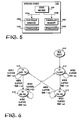
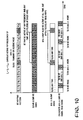
Figures 8a-8b , wherein a period of operation for the wireless devices ofFig. 1 in accordance with each of two alternate embodiments are shown. In each of these two alternate embodiments, first protocol ofwireless devices 104a ofnetwork 108a is assumed to be a frequency hopping protocol as shown, i.e.wireless devices 104a hop from frequency to frequency in accordance with a pseudo random pattern to transmit signals. For ease of understanding, second protocol ofwireless devices 104b ofnetwork 108b is assumed to be a constant frequency protocol (although in alternate embodiments, it may also be a frequency hopping protocol). In any event, to illustrate the present invention, at least one of the frequencies of the first protocol is the same frequency of the second protocol. Thus, if some ofdevices devices 104a selects the same frequency for transmission, interference (or collision) between these devices will occur, resulting in one or more transmission failures. For the illustrated example, frequency interference (or collision) is shown to occur at the 7th and 14th hop (f7 and f14). That is, in accordance with the pseudo random pattern, in each of these two hops,devices 104a transmit in the same frequency employed bydevices 104b. An example of a frequency hopping protocol is the Bluetooth protocol, and an example of a protocol having an interfering frequency with Bluetooth is the 802.11 protocol. [Note that the example interference at the 7th and 14th hop is not intended to suggest that the interference occurs at every 7th hop. The interference pattern is dictated by the intersection of the pseudo random pattern followed by thefrequency hopping devices 104a and the frequency employed bydevices 104b.] - To further improve the operating efficiencies of both network, instead of just letting the interfering
devices wireless device 100 coordinates the operation ofdevices devices 104a ordevices 104b are selected to be the "dominant" devices. The non-selected devices are considered to be the dominated devices. The dominated devices are notified, from time to time, to suspend operation to pro-actively avoid interference with the dominant devices, allowing the dominant devices to continue to operate without interference. As result, the time consuming collision detection, back off and retries are substantially reduced, and experience has shown that the overall operating efficiencies of both networks improve, the dominated network as well as the dominant network. -
Fig. 8a illustrates a period of operation whendevices 104a, the frequency hopping devices, are selected to be the dominant devices, whileFig. 8b illustrates a period of operation whendevices 104b are selected to be the dominant devices. That is, underFig. 8a ,devices 104b, upon informed, will temporarily suspend operation to proactively avoid interference, whereas underFig. 8b ,devices 104a, upon informed, will temporarily suspend operation to proactively avoid interference. - Under either one of these embodiments,
wireless device 100 basically operates as earlier described. Exceptwireless device 100 assumes the additional responsibilities of determining the pseudo random frequency hopping pattern ofdevices 104a (in one embodiment, including the interfering frequency), selecting eitherdevices - Referring now to
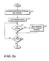
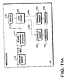
Figs. 9a-9b , wherein the architecture and operational flow ofwireless device 100 having these added responsibilities are shown. As illustrated inFig. 9a ,wireless device 100 is basically the embodiment earlier described referencingFig. 7 , exceptwireless device 100 is further provided with network management application (or network manager) 904 to proactively managingnetwork devices Network manager 904 also subsumes the earlier described responsibilities oftime sharing manager 704, i.e. monitoring the workloads of the two protocols, and adaptively setting the values of t1-t4 for time period T1-T4. - Operationally, as illustrated in
Fig. 9b , upon initialization,network manager 904 monitors the operation ofdevices devices 104a (and in one embodiment, the interfering frequency withdevices 104b), 912. This may be accomplished using any one of a number of techniques known in the art. Next,network manager 904 selects eitherdevices 104a ordevices 104b to be the dominant devices, 914. In one embodiment,network manager 904 makes the selection in accordance with configuration information programmed inconfiguration register 902. In alternate embodiments, other configuration registers, or other techniques known in the art, such as jumpers, may also be employed to assistnetwork manager 904 in making the selection. - Then, on an on going basis,
network manager 904, predicts when interference will occur, using the determined pseudo random pattern and interference frequency, 916. Whenever, an interference is to occur,network manager 904 preemptively notifies the dominated devices to suspend operation accordingly, thereby allowing the dominant devices to operate without interference, 918. [In one embodiment, if the dominated devices aredevices 104a, the notification includes the interfering frequency, and the suspension is conditional, only if the predicted frequency is indeed the interfering frequency.] The process continues, as long as there are wireless devices of bothtypes - In one embodiment,
network manager 904 repeats the calibration periodically. In yet another embodiment,network manager 904 monitors actual interference betweendevices Network manager 904 repeats the calibration, whenever the tracked mean time between interference drops below certain given performance level. - Note that in embodiments where the number of
devices networks device 104a and onedevice 104b innetworks network manager 904 may make the selection of the dominated devices in a dynamic and individualized manner, when an interference is predicted to occur. That is, different device ordevices - As those skilled in the art would appreciate, the above described improved manner of operation (including the embodiment, where suspension is to be conditionally made by
devices 104a) may be practiced with minimal or no change todevices 104,a and 104a, as virtually all network devices are capable of temporarily suspending operation responsive to a request. As to the embodiment where suspension is to be conditionally made bydevices 104a, the conditional performance may be effectuated through addition of simple frequency testing combinatorial logic. - Referring now to
Figure 10 , wherein a period of operation for the wireless devices ofFig. 1 in accordance with another embodiment is shown. Again, first protocol ofwireless devices 104a ofnetwork 108a is assumed to be a frequency hopping protocol, and second protocol ofwireless devices 104b ofnetwork 108b is assumed to be a constant frequency protocol (although it may also be a frequency hopping protocol). Nevertheless, for illustrative purpose, it is suffice that at least one of the frequencies of the first protocol ofwireless devices 104a conflicts with the frequency of the second protocol ofwireless devices 104b as shown, and earlier described. Thus, in like manner, if some ofdevices devices 104a select to transmit in the same frequency, interference, (or collision) will occur, resulting in one or more transmission failures. To further improve the operating efficiencies of both network, instead of just letting the interferingdevices wireless device 100 coordinates the operation ofdevices devices - As illustrated in
Fig. 10 , at each predicted occurrence of interference, bothdevices wireless device 100 remain substantially unchanged, except,wireless device 100 assumes the additional responsibilities of determining the pseudo random frequency hopping pattern ofdevices 104a, the interfering frequency, the corresponding faltering to be employed to cancel the respective interfering signals, and preemptively notifyingdevices - Referring now to
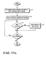
Figs. 11a-11b , wherein the architecture and operational flow ofwireless device 100 having these added responsibilities are shown. As illustrated inFig. 11a ,wireless device 100 is basically the embodiment earlier described referencingFig. 9a . That is,wireless device 100 is also additionally provided withnetwork manager 1104, except the additional responsibilities assumed bynetwork manager 1104 to proactively reduce interference, are slightly different. - As illustrated in
Fig. 11b , upon initialization,network manager 1104 monitors the operation ofdevices devices 104a, and the interfering frequency withdevices network manager 1104 determines the corresponding filtering to be employed bydevices devices Fig. 12 ). That is,devices 104a are to apply a notch filter, inversely formed in accordance with transmit signals ofdevices 104b, whereas,devices 104b are to apply a notch filter, inversely formed in accordance with transmit signals ofdevices 104a. [Notch filters in general are known in the art, and will not be further described.] - Then, on an on going basis,
network manager 1104, predicts when interference will occur, using the determined pseudo random pattern and interference frequency, 1116. Whenever, an interference is to occur,network manager 1104 preemptively notifiesdevices devices types devices 104a may also be conditionally performed, only if the frequency is indeed the same as the interfering frequency.] - As before, in one embodiment,
network manager 1104 repeats the calibration periodically. In yet another embodiment,network manager 1104 monitors actual interference betweendevices Network manager 1104 repeats the calibration, whenever the tracked mean time between interference drops below certain given performance level. - As those skill in the art will appreciate, the immediately described improved manner of operation may also be practiced with minimal change to
devices devices 104a may be additionally provided with simple combinatorial logic to effectuate the conditional application of notch filtering.] - Referring now to
Figure 13 , wherein an overview of the present invention, in accordance with another embodiment, is shown. Similar to the embodiment ofFig. 1 ,wireless device 100 is communicatively coupled todevices 104a anddevices 104b ofwireless networks Wireless device 100 performs transmits and receives of the two protocols, in a coordinated manner, to allowwireless device 100 to operate withdevices 104a anddevices 104b ofwireless network Fig. 1 ,wireless device 100 is provided with asingle wireless transceiver 1302, which includes joint signal transmit/receivesection 1303, and a number of transmit and receive signals up/down conversion sections 1205 sharing joint signal transmit/receivesection 1303.Wireless device 100 further includes controller/signal processing (C/SP) section 1306 to process data for transmission bywireless transceiver 1302, to process signals received bywireless transceiver 1302, and to control the data/signal processing operations as well as the operation ofwireless transceiver 1302. - Additionally, in some embodiments,
wireless device 100 is endowed with a network manager equipped with the capabilities earlier described referencingFigs. 8a-8b and 9a-9b. In other embodiments,wireless device 100 is endowed with a network manager equipped with the capabilities earlier described referencingFigs, 10 and11a -11b. - Thus, a wireless device equipped to substantially operate currently with multiple wireless communication protocols, and various associated methods of operations have been described. While the present invention has been described in terms of the above illustrated embodiments, those skilled in the art will recognize that the invention is not limited to the embodiments described.
- The description is thus to be regarded as illustrative instead of restrictive on the present invention.
Claims (16)
- Apparatus (100) comprising:at least one wireless transceiver (102a, 102b) and at least one controller manager (106a, 106b) coupled to each other to transmit and receive signals, in a coordinated manner, in accordance with a first and a second protocol to and from first and second network devices (104a, 104b) of a first and a second wireless network (108a, 108b) communicatively coupled to the apparatus (100); anda network manager (904) coupled to the at least one wireless transceiver (102a, 102b) and at least one controller manager (106a, 106b) to coordinate transmit and receive operations of said first and second network devices (104a, 104b) of said first and second wireless networks (108a, 108b),wherein the first and/or second protocol is a frequency hopping protocol comprising a plurality of frequencies employed in accordance with a pseudo random pattern, andcharacterised in that:the network manager (904) is arranged to:monitor the operation of the first and second network devices (104a, 104b) to determine a pseudo random frequency hopping pattern for one of the first or second protocols;predict when interference will occur based on the determined pseudo random frequency hopping pattern; andif interference is predicted, either(a) notify the first or second network devices (104a, 104b) to temporarily suspend operations; or(b) notify the first and second network devices (104a, 104b) to apply filtering to cancel the predicted interference,thereby to reduce interference between the first and second network devices (104a, 104b) of the first and second wireless networks (108a, 108b).
- The apparatus of claim 1, wherein the network manager (904) includes logic to select either the first or the second network devices (104a, 104b) as dominated devices, to be operationally dominated by the non-selected first/second network devices (104a, 104b).
- The apparatus of claim 2, wherein the network manager (904) is arranged to notify the dominated devices if an interference is predicted to occur, to temporarily suspend operation to avoid interference with the dominant devices.
- The apparatus of claim 1, wherein the network manager (904) includes logic to determine corresponding filtering to be employed by the first and second network devices (104a, 104b) to correspondingly cancel respective interference signals if an interference is predicted to occur.
- The apparatus of claim 4, wherein the network manager (904) includes logic to determine first and second notch filters, inversely formed in accordance with transmit signals of the second and first network devices (104a, 104b) for the first and second network devices (104a, 104b) respectively.
- The apparatus of claim 1, wherein the first and second protocol are two protocols selected from a group consisting of Bluetooth, 802.11 frequency hopping, 802.11 direct sequence, 802.11a, 802.11b, and Home RF.
- The apparatus of claim 1, wherein the apparatus is a computer having a form factor selected from a group consisting of a desktop type, a notebook type and a palm sized type.
- A method of operation of an apparatus (100) having at least one wireless transceiver (102a, 102b) and at least one controller manager (106a, 106b), the method comprising:monitoring operation of first and second network devices (104a, 104b) of a first and second wireless network (108a, 108b) which are communicatively coupled to the apparatus (100) to transmit and receive signals, in a coordinated manner, to and from the at least one wireless transceiver (102a, 102b) in accordance with a first and a second protocol, the first and/or second protocol being a frequency hopping protocol comprising a plurality of frequencies employed in accordance with a pseudo random pattern, and the monitoring including determining a pseudo random frequency hopping pattern for one of the first or second protocols;predicting when interference will occur between the first and second network devices (104a, 104b) based on the determined pseudo random frequency hopping pattern; andif interference is predicted, either(a) notifying the first or second network devices (104a, 104b) to temporarily suspend operations, or(b) notifying the first and second network devices (104a, 104b) to apply filtering to cancel the predicted interference,thereby to reduce interference between the first and second network devices (104a, 104b) of the first and second wireless networks (108a, 108b).
- A method according to claim 8, wherein step (a) includes:selecting either the first network devices (104a) of the first wireless network (108a) operating in accordance with the first wireless protocol or the second network devices (104b) of the second wireless network (108b) operating in accordance with a second wireless protocol to be dominant devices that operationally dominate the non-selected network devices of the other wireless network; andoperating the at least one wireless transceiver and the at least one controller manager to cause the dominated devices to temporarily suspend operations to avoid interference with the dominant devices.
- A method according to claim 8, wherein step (b) includes
determining the corresponding filtering to be employed by the first and second network devices (104a, 104b) of the first and second wireless networks (108a, 108b), to correspondingly cancel respective interference signals; and
operating the at least one wireless transceiver (102a, 102b) and the at least one controller manager (106a, 106b) to cause the first and second network devices (104a, 104b) to apply the determined filtering if an interference is predicted to occur. - A method according to claim 10, wherein the determining includes determining first and second notch filters, inversely formed in accordance with transmit signals of the second and first network devices (104a, 104b), for the first and second network devices (104a, 104b) respectively.
- A collection of networked apparatuses comprising:a first plurality of apparatuses (104a) wirelessly networked together, with each apparatus being equipped to communicate wirelessly in accordance with a first protocol;a second plurality of apparatuses (104b) wirelessly networked together, with each apparatus being equipped to communicate wirelessly in accordance with a second protocol; anda master apparatus (100) equipped to communicate wirelessly with said first and second plurality of apparatuses (104a, 104b) in accordance with said first and second protocols respectively, as well as equipped to automatically coordinate transmit and receive operations conducted in accordance with said two protocols to enable the master apparatus (100) to manage and control said first and second plurality of apparatuses at the same time, ,wherein the first and/or second protocol is a frequency hopping protocol comprising a plurality of frequencies employed in accordance with a pseudo random pattern, andcharacterised in that:the master apparatus (100) includes a network manager (904) that is arranged to:monitor operation of the first and second plurality of apparatuses (104a, 104b) to determine a pseudo random frequency hopping pattern for one of the first or second protocols;predict when interference will occur based on the determined pseudo random frequency hopping pattern; and,if interference is predicted, either(a) notify the first or second plurality of apparatuses (104a, 104b) to temporarily suspend operations; or(b) notify the first and second plurality of apparatuses (104a, 104b) to apply filtering to cancel the predicted interference,thereby to reduce interference between the first and second plurality of apparatuses.
- The collection of networked apparatuses of claim 12, wherein the master apparatus (100) is equipped to select either the first or the second plurality of apparatuses (104a, 104b) as dominated devices, to be operationally dominated by the non-selected first/second network devices.
- The collection of networked apparatuses of claim 13, wherein the master apparatus (100) is equipped to pre-emptively notify the dominated devices if an interference is predicted to occur, to temporarily suspend operation to avoid interference with the dominant devices.
- The collection of networked apparatuses of claim 12, wherein the master apparatus (100) is equipped to determine the corresponding filtering to be employed by the first and second plurality of apparatuses (104a, 104b) to correspondingly cancel respective interference signals if an interference is predicted to occur.
- The collection of networked apparatuses of claim 15, wherein the master apparatus (100) is equipped to determine first and second notch filters, inversely formed in accordance with transmit signals of the second and first plurality of apparatuses (104a, 104b), for the first and second plurality of apparatuses (104a, 104b) respectively.
Applications Claiming Priority (7)
| Application Number | Priority Date | Filing Date | Title |
|---|---|---|---|
| US09/408,725 US6894988B1 (en) | 1999-09-29 | 1999-09-29 | Wireless apparatus having multiple coordinated transceivers for multiple wireless communication protocols |
| US408725 | 1999-09-29 | ||
| US09/436,458 US6990082B1 (en) | 1999-11-08 | 1999-11-08 | Wireless apparatus having a transceiver equipped to support multiple wireless communication protocols |
| US436458 | 1999-11-08 | ||
| US439946 | 1999-11-12 | ||
| US09/439,946 US6600726B1 (en) | 1999-09-29 | 1999-11-12 | Multiple wireless communication protocol methods and apparatuses |
| PCT/US2000/026805 WO2001024455A1 (en) | 1999-09-29 | 2000-09-29 | Multiple wireless communication protocol methods and apparatuses |
Publications (2)
| Publication Number | Publication Date |
|---|---|
| EP1222777A1 EP1222777A1 (en) | 2002-07-17 |
| EP1222777B1 true EP1222777B1 (en) | 2014-12-24 |
Family
ID=27410769
Family Applications (1)
| Application Number | Title | Priority Date | Filing Date |
|---|---|---|---|
| EP00967090.2A Expired - Lifetime EP1222777B1 (en) | 1999-09-29 | 2000-09-29 | Multiple wireless communication protocol methods and apparatuses |
Country Status (5)
| Country | Link |
|---|---|
| US (2) | US6891857B1 (en) |
| EP (1) | EP1222777B1 (en) |
| JP (1) | JP2003515260A (en) |
| AU (1) | AU7734400A (en) |
| WO (1) | WO2001024455A1 (en) |
Families Citing this family (67)
| Publication number | Priority date | Publication date | Assignee | Title |
|---|---|---|---|---|
| EP1216542B1 (en) * | 1999-09-29 | 2008-12-17 | Mobilian Corporation | Multi-protocol wireless communication methods and apparatuses including quality of service considerations |
| US6782208B1 (en) * | 1999-11-16 | 2004-08-24 | Motorola, Inc. | Wireless communication device and method having coordinated primary and secondary transmitters |
| DE19956318A1 (en) * | 1999-11-23 | 2001-05-31 | Bosch Gmbh Robert | Method for controlling transmission of information specific for the radio transmission protocol i.e. for communication between subscribers of the wireless component of LANs via the core network |
| US7164704B1 (en) * | 1999-12-09 | 2007-01-16 | Texas Instruments Incorporated | Beam forming for transmit using bluetooth modified hopping sequences (BFTBMH) |
| US6804232B1 (en) | 2000-03-27 | 2004-10-12 | Bbnt Solutions Llc | Personal area network with automatic attachment and detachment |
| AU1143602A (en) | 2000-10-06 | 2002-04-15 | Aryya Communications Inc | Systems and methods for interference mitigation among multiple wlan protocols |
| US6526264B2 (en) | 2000-11-03 | 2003-02-25 | Cognio, Inc. | Wideband multi-protocol wireless radio transceiver system |
| US8069254B2 (en) * | 2001-02-28 | 2011-11-29 | Sharp Laboratories Of America, Inc. | Communication period management in a communication system |
| WO2003001742A1 (en) * | 2001-06-25 | 2003-01-03 | Commprize Ventures Limited | Method and system for detection of and dynamic adaptation to radio interference in a shared wireless communications environment |
| JP3600564B2 (en) * | 2001-09-11 | 2004-12-15 | 株式会社東芝 | Portable information device having a plurality of wireless units |
| US7016396B2 (en) * | 2001-11-13 | 2006-03-21 | Telcordia Technologies, Inc. | Unitary bluetooth-enabled terminal having multiple radio interfaces |
| US8005505B2 (en) * | 2002-06-25 | 2011-08-23 | Hewlett-Packard Development Company, L.P. | Identifying remote, external devices and facilitating communication therewith |
| US20040001530A1 (en) * | 2002-06-27 | 2004-01-01 | International Business Machines Corporation | Insertion of null packets to mitigate the effects of interference in wireless communications |
| US6914913B2 (en) * | 2002-08-27 | 2005-07-05 | Motorola, Inc. | Multi-mode interoperable mobile station communications architectures and methods |
| AU2003290581A1 (en) * | 2002-11-04 | 2004-06-07 | Vivato, Inc. | Signal communication coordination |
| JP3993108B2 (en) * | 2003-01-17 | 2007-10-17 | ソニー・エリクソン・モバイルコミュニケーションズ株式会社 | Wireless communication method and wireless communication terminal |
| EP1589677B1 (en) * | 2003-01-31 | 2011-12-21 | Fujitsu Limited | Mobile radio terminal device |
| FR2853800B1 (en) * | 2003-04-11 | 2005-05-27 | Nec Technology Uk Ltd | SOFTWARE ARCHITECTURE AND RADIO ACCESS METHOD OF A MULTI-MODE MOBILE TERMINAL |
| WO2004098141A1 (en) * | 2003-04-24 | 2004-11-11 | Bae Systems Information And Electronic Systems Integration Inc | Multiuser detection aided multiple access differential frequency-hopped spread spectrum |
| GB2402843B (en) * | 2003-06-12 | 2005-09-21 | Nec Technologies | Mobile radio communications device |
| US7406296B2 (en) * | 2003-08-22 | 2008-07-29 | Telefonaktiebolaget L M Ericsson (Publ) | Co-located radio operation |
| US20050048918A1 (en) | 2003-08-29 | 2005-03-03 | Onami, Llc | Radio controller system and method for remote devices |
| US6885337B2 (en) * | 2003-09-10 | 2005-04-26 | Sony Ericsson Mobile Communications Ab | Methods and apparatus for determining the position of a mobile terminal using localized source assistance information |
| US7154933B2 (en) * | 2003-09-25 | 2006-12-26 | Avneesh Agrawal | Interference management for soft handoff and broadcast services in a wireless frequency hopping communication system |
| US7848741B2 (en) | 2003-12-30 | 2010-12-07 | Kivekaes Kalle | Method and system for interference detection |
| US7643811B2 (en) | 2004-05-26 | 2010-01-05 | Nokia Corporation | Method and system for interference detection |
| JP4738329B2 (en) | 2004-05-28 | 2011-08-03 | パナソニック株式会社 | Multi-mode control station, radio communication system, radio station, and radio communication control method |
| US7454171B2 (en) | 2005-02-25 | 2008-11-18 | Nokia Corporation | Method and system for VoIP over WLAN to Bluetooth headset using ACL link and sniff for aligned eSCO transmission |
| US7486932B2 (en) | 2005-02-25 | 2009-02-03 | Nokia Corporation | Method and system for VoIP over WLAN to bluetooth headset using advanced eSCO scheduling |
| ATE384375T1 (en) * | 2005-03-16 | 2008-02-15 | Sony Computer Entertainment Inc | DUAL MODE COMMUNICATION DEVICE HAVING TWO WIRELESS COMMUNICATION MODULES THAT SHARE THE SAME FREQUENCY BAND |
| US7697896B2 (en) * | 2005-03-16 | 2010-04-13 | Sony Computer Entertainment Inc. | Communication apparatus preventing communication interference |
| US8040837B2 (en) * | 2005-06-10 | 2011-10-18 | Panasonic Corporation | Wireless communication apparatus and wireless communication method |
| US7647023B2 (en) * | 2005-06-10 | 2010-01-12 | Broadcom Corporation | Frequency separation for multiple bluetooth devices residing on a single platform |
| US8169980B2 (en) * | 2005-07-11 | 2012-05-01 | Qualcomm Incorporated | Methods and apparatuses for interworking |
| FR2889386B1 (en) * | 2005-07-28 | 2007-10-19 | Sercel Sa | DEVICE AND METHOD FOR CONNECTING TO A WIRELESS NETWORK |
| KR100643300B1 (en) * | 2005-08-08 | 2006-11-10 | 삼성전자주식회사 | Channel allocation method between heterogeneous wireless networks and wireless network apparatus providing the same |
| US8126030B2 (en) * | 2005-08-31 | 2012-02-28 | Motorola Mobility, Inc. | Multi-mode wireless communication device and method |
| US20070082697A1 (en) * | 2005-10-07 | 2007-04-12 | Research In Motion Limited | System and method of handset configuration between cellular and private wireless network modes |
| EP1772994A1 (en) * | 2005-10-07 | 2007-04-11 | Research In Motion Limited | System and method for configuring a handset between a cellular and a private wireless network mode |
| US8180363B2 (en) * | 2005-11-15 | 2012-05-15 | Sony Computer Entertainment Inc. | Communication apparatus preventing communication interference |
| US8447234B2 (en) | 2006-01-18 | 2013-05-21 | Qualcomm Incorporated | Method and system for powering an electronic device via a wireless link |
| US9130602B2 (en) | 2006-01-18 | 2015-09-08 | Qualcomm Incorporated | Method and apparatus for delivering energy to an electrical or electronic device via a wireless link |
| US20070180130A1 (en) * | 2006-02-01 | 2007-08-02 | Arnold William C | Method and apparatus for multi-protocol digital communications |
| US20070183352A1 (en) * | 2006-02-08 | 2007-08-09 | Mustafa Muhammad | Methods and apparatus for providing a shared server system for a platform of multiple wireless communication devices |
| US8064370B2 (en) * | 2006-03-02 | 2011-11-22 | Panasonic Corporation | Transmitting device, wireless communication system and transmitting method |
| GB2438666B (en) * | 2006-06-01 | 2008-08-06 | Toshiba Res Europ Ltd | Method to support multiple mobility protocols in a flexible reconfigurable mobile terminal |
| US8023552B2 (en) * | 2006-09-22 | 2011-09-20 | Alcatel Lucent | Methods of discovering neighbors in opportunistic open access ad hoc wireless networks |
| US9774086B2 (en) | 2007-03-02 | 2017-09-26 | Qualcomm Incorporated | Wireless power apparatus and methods |
| US8203983B2 (en) * | 2007-03-15 | 2012-06-19 | Lantiq Deutschland Gmbh | Multi-domain network with centralized management |
| US9124120B2 (en) | 2007-06-11 | 2015-09-01 | Qualcomm Incorporated | Wireless power system and proximity effects |
| CN103187629B (en) | 2007-08-09 | 2016-08-24 | 高通股份有限公司 | Increase the Q factor of resonator |
| CA2706629C (en) * | 2008-01-24 | 2013-10-29 | Suncor Energy Inc. | Method, system and media for wireless process control of mobile equipment |
| US8170488B2 (en) * | 2008-03-11 | 2012-05-01 | Intel Corporation | Mitigation of internetwork interference |
| US8629576B2 (en) | 2008-03-28 | 2014-01-14 | Qualcomm Incorporated | Tuning and gain control in electro-magnetic power systems |
| US8842554B2 (en) * | 2008-05-07 | 2014-09-23 | Mitsubishi Electric Research Laboratories, Inc. | Antenna selection with frequency-hopped sounding reference signals |
| US9025471B2 (en) * | 2008-05-07 | 2015-05-05 | Mitsubishi Electric Research Laboratories, Inc. | Antenna selection with frequency-hopped sounding reference signals |
| US20100035562A1 (en) * | 2008-08-05 | 2010-02-11 | Motorola, Inc. | Method and System for Signal Processing and Transmission |
| WO2010094119A1 (en) * | 2009-02-23 | 2010-08-26 | Sierra Wireless, Inc. | Apparatus providing plural wireless transceivers within a desired power budget and associated method |
| US8428518B2 (en) * | 2009-09-11 | 2013-04-23 | Intel Corporation | Traffic constraints in a mmWAVE wireless network |
| US9204486B2 (en) * | 2012-03-30 | 2015-12-01 | Texas Instruments Incorporated | Coexistence of wireless sensor networks with other wireless networks |
| US9601267B2 (en) | 2013-07-03 | 2017-03-21 | Qualcomm Incorporated | Wireless power transmitter with a plurality of magnetic oscillators |
| US10102176B2 (en) * | 2015-02-06 | 2018-10-16 | Apple Inc. | Methods and apparatus for rapid switching of hardware configurations with a speed limited bus |
| US10531228B2 (en) * | 2015-12-16 | 2020-01-07 | Sk Planet Co., Ltd. | Approaching user detection, user authentication and location registration method and apparatus based on RF fingerprint |
| US10672252B2 (en) | 2015-12-31 | 2020-06-02 | Delta Faucet Company | Water sensor |
| US10586833B2 (en) * | 2018-05-09 | 2020-03-10 | Microsoft Technology Licensing, Llc | OLED display color compensation |
| JP7239605B2 (en) * | 2018-11-09 | 2023-03-14 | 株式会社ソニー・インタラクティブエンタテインメント | Communication device and connection destination determination method |
| US11064384B2 (en) * | 2019-02-19 | 2021-07-13 | Mediatek Inc. | Apparatuses and methods for multipath communications using a plurality of wireless technologies |
Citations (1)
| Publication number | Priority date | Publication date | Assignee | Title |
|---|---|---|---|---|
| EP0621707A2 (en) * | 1993-04-22 | 1994-10-26 | International Business Machines Corporation | Frequency hopping pattern assignment and control in multiple autonomous collocated radio networks |
Family Cites Families (15)
| Publication number | Priority date | Publication date | Assignee | Title |
|---|---|---|---|---|
| AU7210894A (en) | 1993-06-25 | 1995-01-17 | Xircom, Inc. | Virtual carrier detection for wireless local area network with distributed control |
| JP3248348B2 (en) | 1994-03-15 | 2002-01-21 | 松下電器産業株式会社 | Communication method and communication device |
| JP3349861B2 (en) | 1995-03-17 | 2002-11-25 | 富士通株式会社 | Wireless LAN system |
| JPH09326713A (en) | 1996-06-05 | 1997-12-16 | Sharp Corp | Dual mode cellular telephone system |
| US5812930A (en) * | 1996-07-10 | 1998-09-22 | International Business Machines Corp. | Information handling systems with broadband and narrowband communication channels between repository and display systems |
| DE19651708A1 (en) * | 1996-12-12 | 1998-06-25 | Altvater Air Data Systems Gmbh | Network for the transmission of data packets and method for operating the network |
| US6272120B1 (en) * | 1997-01-28 | 2001-08-07 | Cisco Technology, Inc. | Multi-radio bridge |
| US6608832B2 (en) | 1997-09-25 | 2003-08-19 | Telefonaktiebolaget Lm Ericsson | Common access between a mobile communications network and an external network with selectable packet-switched and circuit-switched and circuit-switched services |
| GB9725659D0 (en) | 1997-12-03 | 1998-02-04 | Nokia Mobile Phones Ltd | The LPRF system with frequency hopping extensions |
| US6928266B1 (en) * | 1999-11-12 | 2005-08-09 | Intel Corporation | Wireless apparatus interference avoidance/resolution method and apparatuses |
| US6990082B1 (en) * | 1999-11-08 | 2006-01-24 | Intel Corporation | Wireless apparatus having a transceiver equipped to support multiple wireless communication protocols |
| US6894988B1 (en) * | 1999-09-29 | 2005-05-17 | Intel Corporation | Wireless apparatus having multiple coordinated transceivers for multiple wireless communication protocols |
| US6600726B1 (en) * | 1999-09-29 | 2003-07-29 | Mobilian Corporation | Multiple wireless communication protocol methods and apparatuses |
| US6278723B1 (en) * | 2000-03-08 | 2001-08-21 | Motorola, Inc. | Method and apparatus for minimizing a probability of self-interference among neighboring wireless networks |
| US6643522B1 (en) * | 2000-03-27 | 2003-11-04 | Sharp Laboratories Of America, Inc. | Method and apparatus providing simultaneous dual mode operations for radios in the shared spectrum |
-
2000
- 2000-04-27 US US09/560,672 patent/US6891857B1/en not_active Expired - Lifetime
- 2000-09-29 EP EP00967090.2A patent/EP1222777B1/en not_active Expired - Lifetime
- 2000-09-29 AU AU77344/00A patent/AU7734400A/en not_active Abandoned
- 2000-09-29 JP JP2001527513A patent/JP2003515260A/en not_active Abandoned
- 2000-09-29 WO PCT/US2000/026805 patent/WO2001024455A1/en active Search and Examination
-
2003
- 2003-06-17 US US10/464,688 patent/US7239615B2/en not_active Expired - Lifetime
Patent Citations (1)
| Publication number | Priority date | Publication date | Assignee | Title |
|---|---|---|---|---|
| EP0621707A2 (en) * | 1993-04-22 | 1994-10-26 | International Business Machines Corporation | Frequency hopping pattern assignment and control in multiple autonomous collocated radio networks |
Also Published As
| Publication number | Publication date |
|---|---|
| US7239615B2 (en) | 2007-07-03 |
| US20030214961A1 (en) | 2003-11-20 |
| JP2003515260A (en) | 2003-04-22 |
| AU7734400A (en) | 2001-04-30 |
| WO2001024455A1 (en) | 2001-04-05 |
| US6891857B1 (en) | 2005-05-10 |
| EP1222777A1 (en) | 2002-07-17 |
Similar Documents
| Publication | Publication Date | Title |
|---|---|---|
| EP1222777B1 (en) | Multiple wireless communication protocol methods and apparatuses | |
| US6600726B1 (en) | Multiple wireless communication protocol methods and apparatuses | |
| EP1216542B1 (en) | Multi-protocol wireless communication methods and apparatuses including quality of service considerations | |
| EP1216544B1 (en) | A wireless apparatus having multiple coordinated transceivers for multiple wireless communication protocols | |
| US6990082B1 (en) | Wireless apparatus having a transceiver equipped to support multiple wireless communication protocols | |
| EP1243099B1 (en) | Wireless apparatus interference avoidance/resolution methods and apparatuses | |
| EP1216545B1 (en) | Multiple wireless communication protocol methods and apparatuses including proactive reduction of interference | |
| US20070223408A1 (en) | Method and Apparatus for Intelligent Seamless Network Switching | |
| JP2003008681A (en) | Information processing apparatus and communication system switching method | |
| US20040015571A1 (en) | Dynamic determination of network configuration | |
| WO2001024458A9 (en) | Wireless communication of concurrent voice and data using overlapping protocols | |
| RX | ‘06L’, CONTROLLER conmouenh M106! | |
| JP2000151618A (en) | Network system, communication apparatus and communication control method | |
| JP2868701B2 (en) | Network equipment | |
| JPS61293043A (en) | Message exchange system for control of network system | |
| JPH1127296A (en) | Network monitoring system | |
| JPH05268224A (en) | Local area network system | |
| JPH11250024A (en) | Terminal state management method, system device therefor and recording medium recorded with terminal state management program | |
| JP2004078588A (en) | Status monitoring system and method by mirroring |
Legal Events
| Date | Code | Title | Description |
|---|---|---|---|
| PUAI | Public reference made under article 153(3) epc to a published international application that has entered the european phase |
Free format text: ORIGINAL CODE: 0009012 |
|
| 17P | Request for examination filed |
Effective date: 20020418 |
|
| AK | Designated contracting states |
Kind code of ref document: A1 Designated state(s): AT BE CH CY DE DK ES FI FR GB GR IE IT LI LU MC NL PT SE |
|
| AX | Request for extension of the european patent |
Free format text: AL;LT;LV;MK;RO;SI |
|
| RIN1 | Information on inventor provided before grant (corrected) |
Inventor name: ZEHAVI, EPHRAIM Inventor name: GINOSAR, RAN Inventor name: MONELLO, BREET, A. Inventor name: NEVO, RON |
|
| 17Q | First examination report despatched |
Effective date: 20061017 |
|
| 17Q | First examination report despatched |
Effective date: 20061017 |
|
| RAP1 | Party data changed (applicant data changed or rights of an application transferred) |
Owner name: INTEL CORPORATION |
|
| REG | Reference to a national code |
Ref country code: DE Ref legal event code: R079 Ref document number: 60048821 Country of ref document: DE Free format text: PREVIOUS MAIN CLASS: H04L0012280000 Ipc: H04L0012660000 |
|
| GRAP | Despatch of communication of intention to grant a patent |
Free format text: ORIGINAL CODE: EPIDOSNIGR1 |
|
| INTG | Intention to grant announced |
Effective date: 20140711 |
|
| RIC1 | Information provided on ipc code assigned before grant |
Ipc: H04W 88/06 20090101ALI20140627BHEP Ipc: H04L 29/06 20060101ALI20140627BHEP Ipc: H04L 12/66 20060101AFI20140627BHEP |
|
| GRAS | Grant fee paid |
Free format text: ORIGINAL CODE: EPIDOSNIGR3 |
|
| GRAA | (expected) grant |
Free format text: ORIGINAL CODE: 0009210 |
|
| AK | Designated contracting states |
Kind code of ref document: B1 Designated state(s): AT BE CH CY DE DK ES FI FR GB GR IE IT LI LU MC NL PT SE |
|
| REG | Reference to a national code |
Ref country code: GB Ref legal event code: FG4D |
|
| REG | Reference to a national code |
Ref country code: CH Ref legal event code: EP |
|
| REG | Reference to a national code |
Ref country code: IE Ref legal event code: FG4D |
|
| REG | Reference to a national code |
Ref country code: AT Ref legal event code: REF Ref document number: 703614 Country of ref document: AT Kind code of ref document: T Effective date: 20150115 |
|
| REG | Reference to a national code |
Ref country code: DE Ref legal event code: R096 Ref document number: 60048821 Country of ref document: DE Effective date: 20150212 |
|
| REG | Reference to a national code |
Ref country code: NL Ref legal event code: VDEP Effective date: 20141224 |
|
| PG25 | Lapsed in a contracting state [announced via postgrant information from national office to epo] |
Ref country code: FI Free format text: LAPSE BECAUSE OF FAILURE TO SUBMIT A TRANSLATION OF THE DESCRIPTION OR TO PAY THE FEE WITHIN THE PRESCRIBED TIME-LIMIT Effective date: 20141224 |
|
| PG25 | Lapsed in a contracting state [announced via postgrant information from national office to epo] |
Ref country code: GR Free format text: LAPSE BECAUSE OF FAILURE TO SUBMIT A TRANSLATION OF THE DESCRIPTION OR TO PAY THE FEE WITHIN THE PRESCRIBED TIME-LIMIT Effective date: 20150325 Ref country code: SE Free format text: LAPSE BECAUSE OF FAILURE TO SUBMIT A TRANSLATION OF THE DESCRIPTION OR TO PAY THE FEE WITHIN THE PRESCRIBED TIME-LIMIT Effective date: 20141224 |
|
| REG | Reference to a national code |
Ref country code: AT Ref legal event code: MK05 Ref document number: 703614 Country of ref document: AT Kind code of ref document: T Effective date: 20141224 |
|
| PG25 | Lapsed in a contracting state [announced via postgrant information from national office to epo] |
Ref country code: NL Free format text: LAPSE BECAUSE OF FAILURE TO SUBMIT A TRANSLATION OF THE DESCRIPTION OR TO PAY THE FEE WITHIN THE PRESCRIBED TIME-LIMIT Effective date: 20141224 |
|
| PG25 | Lapsed in a contracting state [announced via postgrant information from national office to epo] |
Ref country code: ES Free format text: LAPSE BECAUSE OF FAILURE TO SUBMIT A TRANSLATION OF THE DESCRIPTION OR TO PAY THE FEE WITHIN THE PRESCRIBED TIME-LIMIT Effective date: 20141224 |
|
| PG25 | Lapsed in a contracting state [announced via postgrant information from national office to epo] |
Ref country code: AT Free format text: LAPSE BECAUSE OF FAILURE TO SUBMIT A TRANSLATION OF THE DESCRIPTION OR TO PAY THE FEE WITHIN THE PRESCRIBED TIME-LIMIT Effective date: 20141224 |
|
| REG | Reference to a national code |
Ref country code: DE Ref legal event code: R097 Ref document number: 60048821 Country of ref document: DE |
|
| PG25 | Lapsed in a contracting state [announced via postgrant information from national office to epo] |
Ref country code: DK Free format text: LAPSE BECAUSE OF FAILURE TO SUBMIT A TRANSLATION OF THE DESCRIPTION OR TO PAY THE FEE WITHIN THE PRESCRIBED TIME-LIMIT Effective date: 20141224 |
|
| PLBE | No opposition filed within time limit |
Free format text: ORIGINAL CODE: 0009261 |
|
| STAA | Information on the status of an ep patent application or granted ep patent |
Free format text: STATUS: NO OPPOSITION FILED WITHIN TIME LIMIT |
|
| 26N | No opposition filed |
Effective date: 20150925 |
|
| PG25 | Lapsed in a contracting state [announced via postgrant information from national office to epo] |
Ref country code: IT Free format text: LAPSE BECAUSE OF FAILURE TO SUBMIT A TRANSLATION OF THE DESCRIPTION OR TO PAY THE FEE WITHIN THE PRESCRIBED TIME-LIMIT Effective date: 20141224 |
|
| PG25 | Lapsed in a contracting state [announced via postgrant information from national office to epo] |
Ref country code: LU Free format text: LAPSE BECAUSE OF FAILURE TO SUBMIT A TRANSLATION OF THE DESCRIPTION OR TO PAY THE FEE WITHIN THE PRESCRIBED TIME-LIMIT Effective date: 20150929 Ref country code: MC Free format text: LAPSE BECAUSE OF FAILURE TO SUBMIT A TRANSLATION OF THE DESCRIPTION OR TO PAY THE FEE WITHIN THE PRESCRIBED TIME-LIMIT Effective date: 20141224 |
|
| REG | Reference to a national code |
Ref country code: CH Ref legal event code: PL |
|
| PG25 | Lapsed in a contracting state [announced via postgrant information from national office to epo] |
Ref country code: BE Free format text: LAPSE BECAUSE OF FAILURE TO SUBMIT A TRANSLATION OF THE DESCRIPTION OR TO PAY THE FEE WITHIN THE PRESCRIBED TIME-LIMIT Effective date: 20141224 |
|
| REG | Reference to a national code |
Ref country code: IE Ref legal event code: MM4A |
|
| REG | Reference to a national code |
Ref country code: FR Ref legal event code: ST Effective date: 20160531 |
|
| PG25 | Lapsed in a contracting state [announced via postgrant information from national office to epo] |
Ref country code: IE Free format text: LAPSE BECAUSE OF NON-PAYMENT OF DUE FEES Effective date: 20150929 Ref country code: CH Free format text: LAPSE BECAUSE OF NON-PAYMENT OF DUE FEES Effective date: 20150930 Ref country code: LI Free format text: LAPSE BECAUSE OF NON-PAYMENT OF DUE FEES Effective date: 20150930 |
|
| PG25 | Lapsed in a contracting state [announced via postgrant information from national office to epo] |
Ref country code: FR Free format text: LAPSE BECAUSE OF NON-PAYMENT OF DUE FEES Effective date: 20150930 |
|
| PGFP | Annual fee paid to national office [announced via postgrant information from national office to epo] |
Ref country code: DE Payment date: 20160920 Year of fee payment: 17 Ref country code: GB Payment date: 20160928 Year of fee payment: 17 |
|
| PG25 | Lapsed in a contracting state [announced via postgrant information from national office to epo] |
Ref country code: CY Free format text: LAPSE BECAUSE OF FAILURE TO SUBMIT A TRANSLATION OF THE DESCRIPTION OR TO PAY THE FEE WITHIN THE PRESCRIBED TIME-LIMIT Effective date: 20141224 |
|
| REG | Reference to a national code |
Ref country code: DE Ref legal event code: R119 Ref document number: 60048821 Country of ref document: DE |
|
| GBPC | Gb: european patent ceased through non-payment of renewal fee |
Effective date: 20170929 |
|
| PG25 | Lapsed in a contracting state [announced via postgrant information from national office to epo] |
Ref country code: GB Free format text: LAPSE BECAUSE OF NON-PAYMENT OF DUE FEES Effective date: 20170929 Ref country code: PT Free format text: LAPSE BECAUSE OF FAILURE TO SUBMIT A TRANSLATION OF THE DESCRIPTION OR TO PAY THE FEE WITHIN THE PRESCRIBED TIME-LIMIT Effective date: 20141224 Ref country code: DE Free format text: LAPSE BECAUSE OF NON-PAYMENT OF DUE FEES Effective date: 20180404 |