EP1221403B1 - Multi-function steering-wheel - Google Patents
Multi-function steering-wheel Download PDFInfo
- Publication number
- EP1221403B1 EP1221403B1 EP02380004A EP02380004A EP1221403B1 EP 1221403 B1 EP1221403 B1 EP 1221403B1 EP 02380004 A EP02380004 A EP 02380004A EP 02380004 A EP02380004 A EP 02380004A EP 1221403 B1 EP1221403 B1 EP 1221403B1
- Authority
- EP
- European Patent Office
- Prior art keywords
- wheel
- steering
- signals
- function
- accordance
- Prior art date
- Legal status (The legal status is an assumption and is not a legal conclusion. Google has not performed a legal analysis and makes no representation as to the accuracy of the status listed.)
- Expired - Lifetime
Links
Images

Classifications
-
- B—PERFORMING OPERATIONS; TRANSPORTING
- B60—VEHICLES IN GENERAL
- B60Q—ARRANGEMENT OF SIGNALLING OR LIGHTING DEVICES, THE MOUNTING OR SUPPORTING THEREOF OR CIRCUITS THEREFOR, FOR VEHICLES IN GENERAL
- B60Q1/00—Arrangement of optical signalling or lighting devices, the mounting or supporting thereof or circuits therefor
- B60Q1/0076—Switches therefor
- B60Q1/0082—Switches therefor mounted on the steering wheel
-
- B—PERFORMING OPERATIONS; TRANSPORTING
- B60—VEHICLES IN GENERAL
- B60R—VEHICLES, VEHICLE FITTINGS, OR VEHICLE PARTS, NOT OTHERWISE PROVIDED FOR
- B60R11/00—Arrangements for holding or mounting articles, not otherwise provided for
- B60R11/02—Arrangements for holding or mounting articles, not otherwise provided for for radio sets, television sets, telephones, or the like; Arrangement of controls thereof
- B60R11/0264—Arrangements for holding or mounting articles, not otherwise provided for for radio sets, television sets, telephones, or the like; Arrangement of controls thereof for control means
-
- B—PERFORMING OPERATIONS; TRANSPORTING
- B60—VEHICLES IN GENERAL
- B60R—VEHICLES, VEHICLE FITTINGS, OR VEHICLE PARTS, NOT OTHERWISE PROVIDED FOR
- B60R11/00—Arrangements for holding or mounting articles, not otherwise provided for
- B60R2011/0001—Arrangements for holding or mounting articles, not otherwise provided for characterised by position
- B60R2011/0003—Arrangements for holding or mounting articles, not otherwise provided for characterised by position inside the vehicle
- B60R2011/001—Vehicle control means, e.g. steering-wheel or column
Definitions
- the object of the present invention relates to a multifunction steering-wheel, in particular, to a steering wheel of the type of those which are mounted in motor vehicles, which contributes essential characteristics of innovation and notable benefits with respect to the means known and employed for the same ends in the present state of the art.
- the invention proposes the act of equipping a motor car steering wheel as disclosed in DE 3917613 with a device whereby an unlimited number of functions can be selected and executed, said device being of a truly simple design, and foreseen in such a manner that it may be installed in a previously selected position, whereby it proves really comfortable to handle, within the reach of the user without the latter having to adopt uncomfortable postures or that can distract him whilst steering the vehicle.
- the device proposed by the invention for its incorporation in the multifunction steering wheel includes the additional advantage of employing a reduced number of connecting cables for the execution of all the functions for which it has been foreseen.
- the field of application of the invention lies, clearly, within the industrial sector dedicated to the manufacture and/or installation of auxiliary elements for motor cars, in particular elements associated with the steering wheel.
- buttons incorporated on the steering wheel of a motor car intended for the selection and control of some functions associated therewith.
- Such buttons are distributed in a strategic manner; organised so that they result comfortable to use and do not imply for the user any impediment whatever regarding their use, especially when said user is performing vehicle-steering tasks.
- the fundamental objective proposed by the present invention is the act of perfecting the systems already existing, by means of creating an improved device, capable of being installed in the steering wheel of a motor car in a comfortable position within easy reach for the user, said device being materialised in a simple floating wheel, associated with means capable of recognising the direction of rotation of said wheel for the purpose of deciding whether it is desired to select a determined function, or to increase or decrease the magnitude of that function.
- Mechanical means exist for securing the wheel in the chosen position, as well as a pushbutton for establishing the function selected.
- control of the different functions is carried out with the help of two microprocessors, connected by means of a suitable data bus, of those where one of them serves to encode the signals received, and the second, based on the encoded signal received from the first, performs the selection of a different output for each function.
- the concept of the device is extremely simple, easy and comfortable to use, and it is capable of controlling an unlimited number of functions with minimum wiring between the components.
- the invention has foreseen that this embodiment incorporates a pair of optocouplers 4, of those where one of them has the role of emitter and the other that of receiver of the light signal emitted by the first, receiving said signal through the radial openings of the interior wheel 3.
- a pair of optocouplers 4 of those where one of them has the role of emitter and the other that of receiver of the light signal emitted by the first, receiving said signal through the radial openings of the interior wheel 3.
- Each stable position of the wheel corresponds with a function, such that, with the rotation of the wheel, it is possible to select, at will, the different functions that can be performed.
- the confirmation of the position chosen (that is, of the function selected) is carried out mechanically by the closing of a switch 6 in association with the wheel.
- the invention has furthermore fores
- Figure 4 shows a configuration entirely equivalent, from the functional point of view, to that described in relation with Figure 2, and comprises a part 8, provided with flexible pins, such that the rotation of said part causes the aforementioned flexible pins to close or open two independent circuits for the production of the out-of-phase signals that appear also represented in Figure 6 of the drawings; it also has a switch 6 for confirming the function chosen.
- the rotation of said part 8 is carried out by transmission through, for example, gearing which runs directly from the floating wheel to the part 8, through the intermediate part 5.
- the floating wheel 2 is made to rotate in the direction desired, depending on the function that is to be selected, and once its position has been reached, it is sufficient to depress the switch (6) to confirm the selection that has been made.
- the assembly includes means for generating the two signals aforementioned.
- Each signal serves, as has already been stated, to carry out a clearly differentiated mission.
- the pulse of the first signal can be employed advantageously to change the function in question (for example, increase or decrease the volume of a radio receiver, or whatever other function), whilst the second signal, out of phase, as is known, with respect to the first, determines the direction of rotation of the wheel, and therefore the form in which the selection is made from a pre-established initial position.
- the electronic means associated with the assembly includes a first microprocessor (not shown), in which the signals are received, and once encoded, it sends them to a second microprocessor, by means of which the output that corresponds to each function is selected. Moreover said microprocessors serve to reset the selected function to 0 after a determined period of time has elapsed without the pushbutton having been actuated, that is, if no signal is received from the latter.
- the monitoring of the function selected or active at any given moment is carried out preferably by means of a display unit, which can be incorporated in the wheel, or where appropriate by means of light-emitting indicators which can be fitted in the pertinent pushbutton.
- the steering wheel can also incorporate one or several pushbuttons, capable of being secured to whatever part thereof, namely, the framework or the covering of said wheel, making use of screws, clips or whatever other mechanical union that ensures the rigid fastening to the steering wheel and which impedes the projection thereof toward the occupant in the event of an accident.
- the location of said pushbuttons has to be as accessible as possible for the driver, the latter remaining in a comfortable position.
- they can be located on the front face or rear face of the steering wheel, on the arms, on the rim or on the central module.
- the invention has also foreseen that the device be situated in a position, raised, with respect to the plane of the steering wheel, such that the driver actuates it only in an intentional way, and not involuntarily when the former has his hands resting on said wheel.
- the device which has been described above offers the additional benefit that the wiring necessary for its correct installation is considerably reduced, since use is made of only one data bus.
Abstract
Description
- The object of the present invention relates to a multifunction steering-wheel, in particular, to a steering wheel of the type of those which are mounted in motor vehicles, which contributes essential characteristics of innovation and notable benefits with respect to the means known and employed for the same ends in the present state of the art.
- In a more specific manner, the invention proposes the act of equipping a motor car steering wheel as disclosed in DE 3917613 with a device whereby an unlimited number of functions can be selected and executed, said device being of a truly simple design, and foreseen in such a manner that it may be installed in a previously selected position, whereby it proves really comfortable to handle, within the reach of the user without the latter having to adopt uncomfortable postures or that can distract him whilst steering the vehicle. Moreover, the device proposed by the invention for its incorporation in the multifunction steering wheel, includes the additional advantage of employing a reduced number of connecting cables for the execution of all the functions for which it has been foreseen.
- The field of application of the invention lies, clearly, within the industrial sector dedicated to the manufacture and/or installation of auxiliary elements for motor cars, in particular elements associated with the steering wheel.
- The fact is generally known of the increasingly frequent utilisation of buttons incorporated on the steering wheel of a motor car, intended for the selection and control of some functions associated therewith. Such buttons are distributed in a strategic manner; organised so that they result comfortable to use and do not imply for the user any impediment whatever regarding their use, especially when said user is performing vehicle-steering tasks.
- In this sense, the act, increasing widespread, is known of incorporating means on the steering wheel in order that the driver of the vehicle may operate principally, without separating his hands from the wheel, the controls associated with the radio set, cassette or CD player. All of which requires the pertinent internal wiring from the steering wheel, which in many cases comes to be bulky and complex.
- Despite the known devices offering certain drawbacks, of which some have already been stated above, and being moreover limited to that specific function for which they were developed, it is also certain that they fulfil perfectly the mission for which they are intended, although they do not admit alterations or additions to the functions unless the entire system is adequately reconsidered.
- The fundamental objective proposed by the present invention is the act of perfecting the systems already existing, by means of creating an improved device, capable of being installed in the steering wheel of a motor car in a comfortable position within easy reach for the user, said device being materialised in a simple floating wheel, associated with means capable of recognising the direction of rotation of said wheel for the purpose of deciding whether it is desired to select a determined function, or to increase or decrease the magnitude of that function. Mechanical means exist for securing the wheel in the chosen position, as well as a pushbutton for establishing the function selected.
- The control of the different functions is carried out with the help of two microprocessors, connected by means of a suitable data bus, of those where one of them serves to encode the signals received, and the second, based on the encoded signal received from the first, performs the selection of a different output for each function.
- As may be understood, the concept of the device is extremely simple, easy and comfortable to use, and it is capable of controlling an unlimited number of functions with minimum wiring between the components.
- Other characteristics and benefits of the invention shall become more clear from the detailed description that follows of a preferred embodiment thereof, taken by way of illustrative example and not restrictively, with reference to the figures appended, wherein:
- Figure 1 shows a schematic of a steering wheel bearer of the multifunction device of the invention;
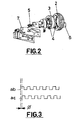
- Figure 2 shows a schematic view in perspective, exploded, of a device constructed in accordance with the invention.
- Figure 3 shows a representation of two square wave signals ab and ac, generated in the device, and out of phase with each other by a certain angle ϕ;
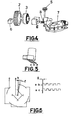
- Figure 4 is a schematic representation in perspective, exploded, of an embodiment of the device of the invention slightly altered with respect to the representation of Figure 2;
- Figure 5 shows the representation of a part fitted with flexible pins capable of rotating on the printed circuit, and
- Figure 6 shows in schematic form the printed circuit employed for the generation of the signals ab and ac as a function of the position occupied by the piece of Figure 5, and of the closing of the pertinent circuit.
-
- The description details the preferred form of embodiment of the invention, said descriptions to be made making use of the drawings appended, throughout which use is made of the same numerical references to designate the identical or similar parts. In this sense, making reference first to Figure 1, it is possible to appreciate the schematic representation of a multifunction steering wheel constructed according to the invention, in which the numerical reference 1 denotes the steering wheel itself, whilst
reference 2 indicates the floating wheel by means of which the device of the invention is materialised,wheels 2 appearing in diametrically opposite, previously selected positions, in such a manner that thewheels 2 prove easy to operate for the user. Of course, these positions are merely by way of illustration and can change depending on the application requirements in each particular case. - With reference to Figures 2 and 3, it is possible to appreciate a form of practical embodiment of the device, in which is distinguished the
aforementioned wheel 2 accessible from the exterior, capable of coupling to aninternal wheel 3, the latter having radial formations implemented in a manner such that they have some gaps having a determined angle of inclination with respect to the radial direction, and optocoupler with superimposed photosensitive areas, or radial gaps and photosensitive areas of the out-of-phase receiver, the object being to be able to obtain signals indicating the direction of rotation of the wheel. To this end, the invention has foreseen that this embodiment incorporates a pair of optocouplers 4, of those where one of them has the role of emitter and the other that of receiver of the light signal emitted by the first, receiving said signal through the radial openings of theinterior wheel 3. There is an engagement mechanism of the different stable positions of thewheel 2, consisting of a ball andspring assembly 5, the ball being capable of lodging in the orifices practiced for this purpose. Each stable position of the wheel corresponds with a function, such that, with the rotation of the wheel, it is possible to select, at will, the different functions that can be performed. The confirmation of the position chosen (that is, of the function selected) is carried out mechanically by the closing of aswitch 6 in association with the wheel. The invention has furthermore foreseen the use of a printedcircuit board 7 for supporting the various components, and it has been designed so as to perform the transmission of the pulses. - According to the foregoing, it can be understood that, depending on the direction of rotation of the wheel, the configuration with which the latter has been endowed causes the signal to be received with a certain shift in phase, just as is shown in Figure 3. This shift in phase has been illustrated graphically as the difference between the two square wave signals ab and ac, and it has been denoted by means of the symbol ϕ. In this manner, the microprocessor means in association are in condition to recognise the direction of rotation of the
wheel 2, and also the final position assumed by said wheel, so determining the variation of the magnitude in question or the change of function. - For its part, Figure 4 shows a configuration entirely equivalent, from the functional point of view, to that described in relation with Figure 2, and comprises a
part 8, provided with flexible pins, such that the rotation of said part causes the aforementioned flexible pins to close or open two independent circuits for the production of the out-of-phase signals that appear also represented in Figure 6 of the drawings; it also has aswitch 6 for confirming the function chosen. The rotation of saidpart 8 is carried out by transmission through, for example, gearing which runs directly from the floating wheel to thepart 8, through theintermediate part 5. - Just as has been stated in the foregoing explanation, the possibility of closing/opening whichever of the two circuits mentioned, by means of the flexible contacts of
rotary part 8 which appears illustrated in Figure 5 of the drawings, provokes the generation of both signals ab and ac. The schematic corresponding to the printed circuit is as shown in Figure 6, in which there appears clearly a first common central position identified with "a", a track "b" surrounding the central position "a", and more external portions of track "c". The generation of the signals ab and ac which appear shown in this same Figure with a phase difference ϕ, is achieved through the rotation of the wheel, one pulse of each signal coinciding with a variation in the engagement of the wheel, permitting detection of the angle turned through and the direction of rotation. - From the foregoing, the manner of operation and exploitation of the device of the invention is easily deduced. As may be understood, the
floating wheel 2 is made to rotate in the direction desired, depending on the function that is to be selected, and once its position has been reached, it is sufficient to depress the switch (6) to confirm the selection that has been made. - In accordance with the invention, the assembly includes means for generating the two signals aforementioned. Each signal serves, as has already been stated, to carry out a clearly differentiated mission. For example, the pulse of the first signal can be employed advantageously to change the function in question (for example, increase or decrease the volume of a radio receiver, or whatever other function), whilst the second signal, out of phase, as is known, with respect to the first, determines the direction of rotation of the wheel, and therefore the form in which the selection is made from a pre-established initial position.
- The electronic means associated with the assembly includes a first microprocessor (not shown), in which the signals are received, and once encoded, it sends them to a second microprocessor, by means of which the output that corresponds to each function is selected. Moreover said microprocessors serve to reset the selected function to 0 after a determined period of time has elapsed without the pushbutton having been actuated, that is, if no signal is received from the latter.
- The monitoring of the function selected or active at any given moment, is carried out preferably by means of a display unit, which can be incorporated in the wheel, or where appropriate by means of light-emitting indicators which can be fitted in the pertinent pushbutton.
- The steering wheel can also incorporate one or several pushbuttons, capable of being secured to whatever part thereof, namely, the framework or the covering of said wheel, making use of screws, clips or whatever other mechanical union that ensures the rigid fastening to the steering wheel and which impedes the projection thereof toward the occupant in the event of an accident. As may be understood, the location of said pushbuttons has to be as accessible as possible for the driver, the latter remaining in a comfortable position. Thus, they can be located on the front face or rear face of the steering wheel, on the arms, on the rim or on the central module.
- Furthermore, the invention has also foreseen that the device be situated in a position, raised, with respect to the plane of the steering wheel, such that the driver actuates it only in an intentional way, and not involuntarily when the former has his hands resting on said wheel.
- As may be understood, the device which has been described above, offers the additional benefit that the wiring necessary for its correct installation is considerably reduced, since use is made of only one data bus.
- It is not deemed necessary to extend further the content of this description for an expert in the matter to be able to comprehend the scope and the benefits resulting from the invention, as well as to develop and implement the object thereof.
- Notwithstanding, it must be understood that the invention has been described according to a preferred embodiment thereof, whereby it can be capable of modification without this implying alteration whatsoever in the essential nature of said invention, it being possible that such alterations, in particular, affect the form, the size and/or the materials of manufacture of the whole or of its parts.
Claims (6)
- Multifunction steering-wheel, specially a steering-wheel of a type of those used for steering motor vehicles, able to incorporate a selection and control device operable and easily accessible from a comfortable position for the driver, situated in such a manner that it may only be actuated in a voluntary manner by said driver, said device being prepared for carrying out an unlimited number of functions, further comprising: a floating wheel (2) to which access is possible from one or more positions of the steering-wheel (1), characterized in that said floating wheel is capable of engagement in an intermediate wheel (3) configured so as to present a multiplicity of radial formations provided with gaps having predetermined geometry and inclination; emitting and receiving means of light signals, constituted by a pair of optocouplers (4), of those in which an emitter transmits the light signal to the receiver through the configuration of said intermediate wheel (3), so that the photosensitive areas of the receiver, out of phase, permit the angle turned through and the direction of rotation of the wheel (2) to be known; a mechanically operated switching means (6), and in association with said wheel (2); means (5) of stable positioning of the different settings of the wheel (2); a printed circuit board (7), in association with the assembly, for holding the components thereof, and electronic means for generating signals and processing the signals received.
- Multifunction steering-wheel in accordance with claim 1, characterised in that each setting of the wheel (2) has an associated determined function (or the variation of the magnitude of said function), confirmation of which is carried out by depressing the switch (6) in association with said wheel (2).
- Multifunction steering-wheel in accordance with claim 1, characterised in that the generation has been foreseen of two signals "ab" and "ac" out of phase with each other by an angle ϕ.
- Multifunction steering-wheel in accordance with claim 1 in association with claim 3, characterised in that the electronic means include two microprocessors, of those in which a first microprocessor carries out the encoding of the signals received and transmits them to the second microprocessor by means of which the enabling is performed of the different outputs associated with each respective function.
- Multifunction steering-wheel in accordance with claim 1, characterised in that in a variant of embodiment, it has been foreseen that the device incorporate a rotary part (8), operable through gearing or the like from the floating wheel (2), provided with flexible contacts, capable of moving over the printed circuit board (7), by means of which contacts the selection is made of two respective circuits which serve to generate the signals "ab" and "ac" out of phase.
- Multifunction steering-wheel in accordance with one or more of the previous claims, characterised in that it further includes the provision of means of displaying the active or selected function, said means being constituted by a display panel or other presentation located in the steering-wheel itself, or where appropriate, by light-emitting indicators associated with the respective pushbuttons.
Applications Claiming Priority (2)
| Application Number | Priority Date | Filing Date | Title |
|---|---|---|---|
| ES200100047 | 2001-01-09 | ||
| ES200100047 | 2001-01-09 |
Publications (3)
| Publication Number | Publication Date |
|---|---|
| EP1221403A2 EP1221403A2 (en) | 2002-07-10 |
| EP1221403A3 EP1221403A3 (en) | 2003-05-07 |
| EP1221403B1 true EP1221403B1 (en) | 2004-10-20 |
Family
ID=8496355
Family Applications (1)
| Application Number | Title | Priority Date | Filing Date |
|---|---|---|---|
| EP02380004A Expired - Lifetime EP1221403B1 (en) | 2001-01-09 | 2002-01-09 | Multi-function steering-wheel |
Country Status (5)
| Country | Link |
|---|---|
| EP (1) | EP1221403B1 (en) |
| AT (1) | ATE280069T1 (en) |
| DE (1) | DE60201612T2 (en) |
| ES (1) | ES2225746T3 (en) |
| PT (1) | PT1221403E (en) |
Cited By (1)
| Publication number | Priority date | Publication date | Assignee | Title |
|---|---|---|---|---|
| CN104220952A (en) * | 2012-03-27 | 2014-12-17 | 德尔福技术有限公司 | Control selector having rotary thumb scroll |
Families Citing this family (4)
| Publication number | Priority date | Publication date | Assignee | Title |
|---|---|---|---|---|
| DE10212781A1 (en) * | 2002-03-22 | 2003-10-02 | Bayerische Motoren Werke Ag | Vehicle steering wheel has switches or buttons on steering wheel spoke which can be operated in mutually perpendicular directions |
| DE10235159B4 (en) * | 2002-08-01 | 2007-09-13 | Daimlerchrysler Ag | Adjustable steering wheel for motor vehicles |
| DE102007053689B4 (en) * | 2007-11-10 | 2017-12-28 | Leopold Kostal Gmbh & Co. Kg | Pressure and drehbetätigbares control for a motor vehicle |
| DE102010049082A1 (en) * | 2010-10-21 | 2012-04-26 | Gm Global Technology Operations Llc (N.D.Ges.D. Staates Delaware) | Steering wheel for a vehicle and vehicle |
Family Cites Families (2)
| Publication number | Priority date | Publication date | Assignee | Title |
|---|---|---|---|---|
| JPH02288117A (en) * | 1989-04-28 | 1990-11-28 | Toyoda Gosei Co Ltd | Knob with switch for steering wheel |
| DE3917613A1 (en) * | 1989-05-31 | 1990-12-06 | Jirka Linhart | Steering wheel with operating elements fitted on its surface - saves spreading controls over dashboard and at door cladding or at roof also under steering wheel or above windscreen |
-
2002
- 2002-01-09 ES ES02380004T patent/ES2225746T3/en not_active Expired - Lifetime
- 2002-01-09 DE DE60201612T patent/DE60201612T2/en not_active Expired - Fee Related
- 2002-01-09 AT AT02380004T patent/ATE280069T1/en not_active IP Right Cessation
- 2002-01-09 PT PT02380004T patent/PT1221403E/en unknown
- 2002-01-09 EP EP02380004A patent/EP1221403B1/en not_active Expired - Lifetime
Cited By (2)
| Publication number | Priority date | Publication date | Assignee | Title |
|---|---|---|---|---|
| CN104220952A (en) * | 2012-03-27 | 2014-12-17 | 德尔福技术有限公司 | Control selector having rotary thumb scroll |
| CN104220952B (en) * | 2012-03-27 | 2016-01-13 | 德尔福技术有限公司 | There is the command selector of rotation roller |
Also Published As
| Publication number | Publication date |
|---|---|
| ES2225746T3 (en) | 2005-03-16 |
| PT1221403E (en) | 2005-02-28 |
| DE60201612T2 (en) | 2005-11-03 |
| DE60201612D1 (en) | 2004-11-25 |
| ATE280069T1 (en) | 2004-11-15 |
| EP1221403A2 (en) | 2002-07-10 |
| EP1221403A3 (en) | 2003-05-07 |
Similar Documents
| Publication | Publication Date | Title |
|---|---|---|
| EP0822119B1 (en) | Multifunctional switching apparatus and a vehicle operating system using the same | |
| US7310084B2 (en) | Multi-way operation switch, input device and input unit | |
| US6300939B1 (en) | Input device | |
| US7579559B2 (en) | Control knob having integrated functionality | |
| JP2002283868A (en) | Storable shifter having electronic gear shift reset | |
| EP1505614B1 (en) | A modular switch and control system for use in a motor vehicle | |
| RU2406636C2 (en) | Automotive steering wheel assembly and method of controlling portable functional component | |
| JP2002347538A (en) | Control device for on-vehicle apparatus | |
| JP2002149324A (en) | Manual input device | |
| EP1108611B1 (en) | Switch structure of steering wheel | |
| US4598237A (en) | Power window control apparatus | |
| CN111824237B (en) | Steering device | |
| EP1221403B1 (en) | Multi-function steering-wheel | |
| JPH10297391A (en) | Switch device for automobile | |
| JP2000003638A (en) | Attaching structure of cable reel to combination switch | |
| US7086292B2 (en) | Force-feedback input device | |
| CN111824238A (en) | Steering device | |
| JP4433252B2 (en) | Remote control transmitter | |
| JP2004136802A (en) | Door for automobile and door trim | |
| GB2281956A (en) | Vehicle steering wheel with airbag and pressure sensor switch | |
| KR101003193B1 (en) | Haptic Switching Unit for Steering Wheel and Haptic Switching System with the same | |
| JP2001297647A (en) | Operation apparatus for vehicle | |
| JP2003153354A (en) | Haptic inputting apparatus | |
| JP2004345552A (en) | In-vehicle apparatus remote-operating system | |
| CN215245081U (en) | Steering device |
Legal Events
| Date | Code | Title | Description |
|---|---|---|---|
| PUAI | Public reference made under article 153(3) epc to a published international application that has entered the european phase |
Free format text: ORIGINAL CODE: 0009012 |
|
| AK | Designated contracting states |
Kind code of ref document: A2 Designated state(s): AT BE CH CY DE DK ES FI FR GB GR IE IT LI LU MC NL PT SE TR |
|
| AX | Request for extension of the european patent |
Free format text: AL;LT;LV;MK;RO;SI |
|
| PUAL | Search report despatched |
Free format text: ORIGINAL CODE: 0009013 |
|
| AK | Designated contracting states |
Designated state(s): AT BE CH CY DE DK ES FI FR GB GR IE IT LI LU MC NL PT SE TR |
|
| AX | Request for extension of the european patent |
Extension state: AL LT LV MK RO SI |
|
| 17P | Request for examination filed |
Effective date: 20031104 |
|
| AKX | Designation fees paid |
Designated state(s): AT BE CH CY DE DK ES FI FR GB GR IE IT LI LU MC NL PT SE TR |
|
| GRAP | Despatch of communication of intention to grant a patent |
Free format text: ORIGINAL CODE: EPIDOSNIGR1 |
|
| GRAS | Grant fee paid |
Free format text: ORIGINAL CODE: EPIDOSNIGR3 |
|
| GRAA | (expected) grant |
Free format text: ORIGINAL CODE: 0009210 |
|
| AK | Designated contracting states |
Kind code of ref document: B1 Designated state(s): AT BE CH CY DE DK ES FI FR GB GR IE IT LI LU MC NL PT SE TR |
|
| PG25 | Lapsed in a contracting state [announced via postgrant information from national office to epo] |
Ref country code: TR Free format text: LAPSE BECAUSE OF FAILURE TO SUBMIT A TRANSLATION OF THE DESCRIPTION OR TO PAY THE FEE WITHIN THE PRESCRIBED TIME-LIMIT Effective date: 20041020 Ref country code: AT Free format text: LAPSE BECAUSE OF FAILURE TO SUBMIT A TRANSLATION OF THE DESCRIPTION OR TO PAY THE FEE WITHIN THE PRESCRIBED TIME-LIMIT Effective date: 20041020 Ref country code: FI Free format text: LAPSE BECAUSE OF FAILURE TO SUBMIT A TRANSLATION OF THE DESCRIPTION OR TO PAY THE FEE WITHIN THE PRESCRIBED TIME-LIMIT Effective date: 20041020 Ref country code: LI Free format text: LAPSE BECAUSE OF FAILURE TO SUBMIT A TRANSLATION OF THE DESCRIPTION OR TO PAY THE FEE WITHIN THE PRESCRIBED TIME-LIMIT Effective date: 20041020 Ref country code: BE Free format text: LAPSE BECAUSE OF FAILURE TO SUBMIT A TRANSLATION OF THE DESCRIPTION OR TO PAY THE FEE WITHIN THE PRESCRIBED TIME-LIMIT Effective date: 20041020 Ref country code: CH Free format text: LAPSE BECAUSE OF FAILURE TO SUBMIT A TRANSLATION OF THE DESCRIPTION OR TO PAY THE FEE WITHIN THE PRESCRIBED TIME-LIMIT Effective date: 20041020 Ref country code: NL Free format text: LAPSE BECAUSE OF FAILURE TO SUBMIT A TRANSLATION OF THE DESCRIPTION OR TO PAY THE FEE WITHIN THE PRESCRIBED TIME-LIMIT Effective date: 20041020 |
|
| REG | Reference to a national code |
Ref country code: GB Ref legal event code: FG4D |
|
| REG | Reference to a national code |
Ref country code: CH Ref legal event code: EP |
|
| REG | Reference to a national code |
Ref country code: IE Ref legal event code: FG4D |
|
| REG | Reference to a national code |
Ref country code: SE Ref legal event code: TRGR |
|
| REF | Corresponds to: |
Ref document number: 60201612 Country of ref document: DE Date of ref document: 20041125 Kind code of ref document: P |
|
| PG25 | Lapsed in a contracting state [announced via postgrant information from national office to epo] |
Ref country code: CY Free format text: LAPSE BECAUSE OF FAILURE TO SUBMIT A TRANSLATION OF THE DESCRIPTION OR TO PAY THE FEE WITHIN THE PRESCRIBED TIME-LIMIT Effective date: 20050109 Ref country code: LU Free format text: LAPSE BECAUSE OF NON-PAYMENT OF DUE FEES Effective date: 20050109 |
|
| PG25 | Lapsed in a contracting state [announced via postgrant information from national office to epo] |
Ref country code: IE Free format text: LAPSE BECAUSE OF NON-PAYMENT OF DUE FEES Effective date: 20050110 |
|
| PG25 | Lapsed in a contracting state [announced via postgrant information from national office to epo] |
Ref country code: DK Free format text: LAPSE BECAUSE OF FAILURE TO SUBMIT A TRANSLATION OF THE DESCRIPTION OR TO PAY THE FEE WITHIN THE PRESCRIBED TIME-LIMIT Effective date: 20050120 Ref country code: GR Free format text: LAPSE BECAUSE OF FAILURE TO SUBMIT A TRANSLATION OF THE DESCRIPTION OR TO PAY THE FEE WITHIN THE PRESCRIBED TIME-LIMIT Effective date: 20050120 |
|
| PG25 | Lapsed in a contracting state [announced via postgrant information from national office to epo] |
Ref country code: MC Free format text: LAPSE BECAUSE OF NON-PAYMENT OF DUE FEES Effective date: 20050131 |
|
| REG | Reference to a national code |
Ref country code: PT Ref legal event code: SC4A Free format text: AVAILABILITY OF NATIONAL TRANSLATION Effective date: 20041221 |
|
| REG | Reference to a national code |
Ref country code: ES Ref legal event code: FG2A Ref document number: 2225746 Country of ref document: ES Kind code of ref document: T3 |
|
| REG | Reference to a national code |
Ref country code: CH Ref legal event code: PL |
|
| NLV1 | Nl: lapsed or annulled due to failure to fulfill the requirements of art. 29p and 29m of the patents act | ||
| ET | Fr: translation filed | ||
| PLBE | No opposition filed within time limit |
Free format text: ORIGINAL CODE: 0009261 |
|
| STAA | Information on the status of an ep patent application or granted ep patent |
Free format text: STATUS: NO OPPOSITION FILED WITHIN TIME LIMIT |
|
| 26N | No opposition filed |
Effective date: 20050721 |
|
| REG | Reference to a national code |
Ref country code: IE Ref legal event code: MM4A |
|
| PGFP | Annual fee paid to national office [announced via postgrant information from national office to epo] |
Ref country code: GB Payment date: 20060104 Year of fee payment: 5 |
|
| PGFP | Annual fee paid to national office [announced via postgrant information from national office to epo] |
Ref country code: PT Payment date: 20060111 Year of fee payment: 5 |
|
| PGFP | Annual fee paid to national office [announced via postgrant information from national office to epo] |
Ref country code: SE Payment date: 20060118 Year of fee payment: 5 |
|
| PG25 | Lapsed in a contracting state [announced via postgrant information from national office to epo] |
Ref country code: SE Free format text: LAPSE BECAUSE OF NON-PAYMENT OF DUE FEES Effective date: 20070110 |
|
| PG25 | Lapsed in a contracting state [announced via postgrant information from national office to epo] |
Ref country code: PT Free format text: LAPSE BECAUSE OF NON-PAYMENT OF DUE FEES Effective date: 20070709 |
|
| REG | Reference to a national code |
Ref country code: PT Ref legal event code: MM4A Free format text: LAPSE DUE TO NON-PAYMENT OF FEES Effective date: 20070709 |
|
| EUG | Se: european patent has lapsed | ||
| GBPC | Gb: european patent ceased through non-payment of renewal fee |
Effective date: 20070109 |
|
| PG25 | Lapsed in a contracting state [announced via postgrant information from national office to epo] |
Ref country code: GB Free format text: LAPSE BECAUSE OF NON-PAYMENT OF DUE FEES Effective date: 20070109 |
|
| PGFP | Annual fee paid to national office [announced via postgrant information from national office to epo] |
Ref country code: ES Payment date: 20081215 Year of fee payment: 8 |
|
| PGFP | Annual fee paid to national office [announced via postgrant information from national office to epo] |
Ref country code: DE Payment date: 20090122 Year of fee payment: 8 |
|
| PGFP | Annual fee paid to national office [announced via postgrant information from national office to epo] |
Ref country code: IT Payment date: 20090127 Year of fee payment: 8 |
|
| PGFP | Annual fee paid to national office [announced via postgrant information from national office to epo] |
Ref country code: FR Payment date: 20090115 Year of fee payment: 8 |
|
| REG | Reference to a national code |
Ref country code: FR Ref legal event code: ST Effective date: 20100930 |
|
| PG25 | Lapsed in a contracting state [announced via postgrant information from national office to epo] |
Ref country code: FR Free format text: LAPSE BECAUSE OF NON-PAYMENT OF DUE FEES Effective date: 20100201 |
|
| PG25 | Lapsed in a contracting state [announced via postgrant information from national office to epo] |
Ref country code: DE Free format text: LAPSE BECAUSE OF NON-PAYMENT OF DUE FEES Effective date: 20100803 |
|
| PG25 | Lapsed in a contracting state [announced via postgrant information from national office to epo] |
Ref country code: IT Free format text: LAPSE BECAUSE OF NON-PAYMENT OF DUE FEES Effective date: 20100109 |
|
| REG | Reference to a national code |
Ref country code: ES Ref legal event code: FD2A Effective date: 20110404 |
|
| PG25 | Lapsed in a contracting state [announced via postgrant information from national office to epo] |
Ref country code: ES Free format text: LAPSE BECAUSE OF NON-PAYMENT OF DUE FEES Effective date: 20110322 |
|
| PG25 | Lapsed in a contracting state [announced via postgrant information from national office to epo] |
Ref country code: ES Free format text: LAPSE BECAUSE OF NON-PAYMENT OF DUE FEES Effective date: 20100110 |