EP1217879A2 - Method and equippment for the thermal conditioning of cabinets containing electronic assemblies - Google Patents
Method and equippment for the thermal conditioning of cabinets containing electronic assemblies Download PDFInfo
- Publication number
- EP1217879A2 EP1217879A2 EP01129577A EP01129577A EP1217879A2 EP 1217879 A2 EP1217879 A2 EP 1217879A2 EP 01129577 A EP01129577 A EP 01129577A EP 01129577 A EP01129577 A EP 01129577A EP 1217879 A2 EP1217879 A2 EP 1217879A2
- Authority
- EP
- European Patent Office
- Prior art keywords
- air
- temperature
- cabinet
- assemblies
- outside
- Prior art date
- Legal status (The legal status is an assumption and is not a legal conclusion. Google has not performed a legal analysis and makes no representation as to the accuracy of the status listed.)
- Granted
Links
Images

Classifications
-
- H—ELECTRICITY
- H05—ELECTRIC TECHNIQUES NOT OTHERWISE PROVIDED FOR
- H05K—PRINTED CIRCUITS; CASINGS OR CONSTRUCTIONAL DETAILS OF ELECTRIC APPARATUS; MANUFACTURE OF ASSEMBLAGES OF ELECTRICAL COMPONENTS
- H05K7/00—Constructional details common to different types of electric apparatus
- H05K7/20—Modifications to facilitate cooling, ventilating, or heating
- H05K7/20536—Modifications to facilitate cooling, ventilating, or heating for racks or cabinets of standardised dimensions, e.g. electronic racks for aircraft or telecommunication equipment
- H05K7/207—Thermal management, e.g. cabinet temperature control
-
- F—MECHANICAL ENGINEERING; LIGHTING; HEATING; WEAPONS; BLASTING
- F24—HEATING; RANGES; VENTILATING
- F24F—AIR-CONDITIONING; AIR-HUMIDIFICATION; VENTILATION; USE OF AIR CURRENTS FOR SCREENING
- F24F1/00—Room units for air-conditioning, e.g. separate or self-contained units or units receiving primary air from a central station
- F24F1/02—Self-contained room units for air-conditioning, i.e. with all apparatus for treatment installed in a common casing
- F24F1/022—Self-contained room units for air-conditioning, i.e. with all apparatus for treatment installed in a common casing comprising a compressor cycle
- F24F1/027—Self-contained room units for air-conditioning, i.e. with all apparatus for treatment installed in a common casing comprising a compressor cycle mounted in wall openings, e.g. in windows
-
- H—ELECTRICITY
- H05—ELECTRIC TECHNIQUES NOT OTHERWISE PROVIDED FOR
- H05K—PRINTED CIRCUITS; CASINGS OR CONSTRUCTIONAL DETAILS OF ELECTRIC APPARATUS; MANUFACTURE OF ASSEMBLAGES OF ELECTRICAL COMPONENTS
- H05K7/00—Constructional details common to different types of electric apparatus
- H05K7/20—Modifications to facilitate cooling, ventilating, or heating
- H05K7/20536—Modifications to facilitate cooling, ventilating, or heating for racks or cabinets of standardised dimensions, e.g. electronic racks for aircraft or telecommunication equipment
- H05K7/20618—Air circulating in different modes under control of air guidance flaps
-
- F—MECHANICAL ENGINEERING; LIGHTING; HEATING; WEAPONS; BLASTING
- F24—HEATING; RANGES; VENTILATING
- F24F—AIR-CONDITIONING; AIR-HUMIDIFICATION; VENTILATION; USE OF AIR CURRENTS FOR SCREENING
- F24F11/00—Control or safety arrangements
- F24F11/0001—Control or safety arrangements for ventilation
- F24F2011/0006—Control or safety arrangements for ventilation using low temperature external supply air to assist cooling
-
- Y—GENERAL TAGGING OF NEW TECHNOLOGICAL DEVELOPMENTS; GENERAL TAGGING OF CROSS-SECTIONAL TECHNOLOGIES SPANNING OVER SEVERAL SECTIONS OF THE IPC; TECHNICAL SUBJECTS COVERED BY FORMER USPC CROSS-REFERENCE ART COLLECTIONS [XRACs] AND DIGESTS
- Y02—TECHNOLOGIES OR APPLICATIONS FOR MITIGATION OR ADAPTATION AGAINST CLIMATE CHANGE
- Y02B—CLIMATE CHANGE MITIGATION TECHNOLOGIES RELATED TO BUILDINGS, e.g. HOUSING, HOUSE APPLIANCES OR RELATED END-USER APPLICATIONS
- Y02B30/00—Energy efficient heating, ventilation or air conditioning [HVAC]
- Y02B30/54—Free-cooling systems
Definitions
- the present invention relates to the cabinets for electronic assemblies, in particular for telecommunication, and more in particular, object of the same is a method and equipment for the thermal conditioning of said cabinets.
- a first solution employs active (or closed circuit) air conditioning systems, whichever the outside temperature is: in the latter, air coming from the cabinets is cooled, and so cooled, it is reintroduced in the cabinets.
- active (or closed circuit) air conditioning systems are disclosed in JP-A-11083354 and JP-A-11135972. Being these systems always in operation, they show high power consumption. Moreover, they originate temperature short-term fluctuations, tied to the transient of the thermal cycle, which reduce the average time between failures. This is an important aspect for assemblies, such as base stations of mobile communication systems placed in areas comparatively difficult to reach by maintenance operators or anyway far from maintenance centres.
- the second solution employs a free ventilation cooling (known as "free cooling"), according to which air drawn from the external environment is let into the cabinet, and hot air coming from the cabinet is exhausted to the outside.
- free ventilation cooling An example is disclosed in WO-A-9414308.
- Free ventilation cooling systems are intrinsically free from short-term fluctuations, however, they are scarcely effective or unusable where there is not a sufficient differential between the outside temperature and the internal one.
- Scope of the invention is to give an air-conditioning method and equipment effective in any climatic condition, enabling a reduced power consumption and minimizing the temperature short-term fluctuations.
- the method according to the invention includes the following steps:
- the equipment according to the invention includes:
- the equipment is housed in a construction module built-in the cabinet to cool.
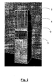
- a cabinet 1 including a given number of modules (three in the example shown in the in figure 2a, 2b, 2c) for electronic assemblies and their power supply devices, and an additional module 3 housing the air conditioning system of the invention.
- Modules 2a - 2c are open at top, to enable the exit of hot air to send to module 3, and at bottom for the inlet of cold air coming from module 3, as indicated by arrows A, B.
- the modules 2a - 2c have height such to define, with the ceiling of cabinet 1, a hollow space 4 to convey hot air to module 3, which in turn shows a rear lowered upper part, as it could be seen in detail in Figures 2 and 3 where this lowered portion has been denoted with the numeric reference 5.
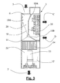
- an inlet opening 6 is made for hot air conveyed by channel 4.
- a lower opening 7 enables to send cold air toward modules 2a-2c, through a hollow space similar to hollow space 4, not shown in the drawings.
- the module 3 houses a system capable of operating both in closed circuit and free ventilation mode. According to the invention, the two types of cooling can be separately and jointly actuated, according to the temperature conditions existing inside and outside the cabinet 1. In particular, three outside temperature bands are identified:
- the front wall of module 3 shows two superimposed openings 8, 9 closed with relevant grates, used for the exhaust of hot air to the environment (arrow C) and for the inlet of air sucked from the external environment (arrow D), respectively, during the free ventilation cooling.
- the upper part placed behind the grates 8, 9 forms an air handling section or chamber 20, and houses a gate 10, with a vertical section, L or obtuse angle shaped, which defines air paths requested by the cooling methods adopted on that moment.
- the position of gate 10 is represented in grey in the figure for the case of sole closed circuit cooling operating, while the position is white coloured when the sole free ventilation cooling is operating.
- the gate 10 is operated by a servomotor 11 controlled by a logic control unit 12 installed in the lower part of the module 3.
- the unit 12 is associated to appropriate sensors, not represented, both of the temperature outside and inside the cabinet, and of the relative humidity of external air, in order to decide the more appropriate cooling method in respect with particular climatic conditions.
- the logic unit can make the gate 10 assume any intermediate position among those shown in fig. 3.
- Devices like unit 12 are well known in the sector of air-conditioning plants.
- module 3 forms an evaporation section or chamber 21 and houses the compressor 13 of the mechanical cooling system and a dripping pan 14 for condensate water.
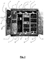
- the cabinet 1 shows also (see figure 1) closure doors, 16, and the door 15 shall in turn be equipped with slots 17, 18 for air passage, matching openings 8, 9. These openings are fit with relevant filters: the opening 18 is equipped with filter to hold air impurities, while opening 17 is fit with attenuation system for the noise cause by air exhaust.
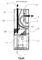
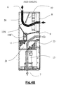
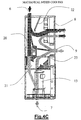
- Figures 4A - 4C show more in detail the air flows corresponding to the use of the sole closed circuit cooling, of the sole free ventilation cooling and of the mixed cooling.
- black arrows indicate hot air and white arrows cold air.
- the upper arm 10A of gate 10 rests against a partition 22 projecting downward from the module ceiling, while the other arm 10B rests against a partition 23 foreseen matching the separation area between chambers 20, 21.
- the gate 10 defines a passage carrying hot air entering the upper opening 6 towards the evaporation chamber 21 (where it is cooled, since the compressor 13 is operating) and from there, to the lower opening 7, while it prevents the passage of air itself towards opening 9 and the exhaust to the environment through this one.Possible external air entering opening 9 is diverted through opening 8 and re-inlet in the environment, without participating in the cooling process.
- the gate is at an intermediate position between those of figures 4A and 4B, enabling the passage to the evaporation section 21 both of air coming from the cabinet through opening 6, and of external air entering opening 9.
- the compressor 13 is operating and therefore also external air is cooled.
- the relevant proportions of the two air inlets will depend on the particular position of the gate, determined by the logic unit 14. This position shall be selected according to the temperature difference between internal and external air, and it could be modified by discrete steps or even continuously, as this difference varies.
- the operation condition corresponding to the intermediate band, for the major part of the operating time of the air-conditioned system during the year.
- the upper threshold could be included for instance between 30°C and 50°C
- the lower temperature threshold between 10°C and 25°C.
- the gate position there could be a variation in the gate position and if the difference between the internal and external temperature varies more than a threshold selected for instance between 2°C and 3°C.
- the humidity threshold causing to pass to the closed circuit cooling could be included for instance between 40% and 80%.
- FIG. 5 shows as a flow chart, the procedure of the invention.
- Te indicates the external air temperature
- T1 and T2 indicate the temperature upper and lower threshold, respectively
- U the relative humidity threshold. The cycle shown is repeated at pre-determined intervals. Considering the previous description the diagram is clear and does not require any additional explanation.
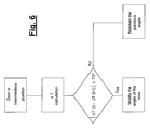
- Figure 6 shows on the contrary the checks on the external and internal temperature made during the mixed cooling operation.
- the difference ⁇ T between the two temperatures, between two subsequent monitoring instants t-1 and t varies of a quantity higher than a given threshold T3, the angle of gate 10 is changed, in order to vary the proportions of external and internal air.
- the essential advantage of the invention is that the free ventilation operation is expanded also to temperatures that otherwise could not employ it, and there is a reduction of the number of thermal cycles in the time unit.
Landscapes
- Engineering & Computer Science (AREA)
- Aviation & Aerospace Engineering (AREA)
- Physics & Mathematics (AREA)
- Thermal Sciences (AREA)
- Microelectronics & Electronic Packaging (AREA)
- Chemical & Material Sciences (AREA)
- Combustion & Propulsion (AREA)
- Mechanical Engineering (AREA)
- General Engineering & Computer Science (AREA)
- Cooling Or The Like Of Electrical Apparatus (AREA)
- Apparatus For Making Beverages (AREA)
- Non-Silver Salt Photosensitive Materials And Non-Silver Salt Photography (AREA)
- Solid-Sorbent Or Filter-Aiding Compositions (AREA)
Abstract
- a closed circuit mechanical cooling of the air drawn from the cabinets, if the outside is higher than a first threshold;
- an open circuit free ventilation cooling, if the outside temperature is lower than a second threshold;
- mixed cooling, in which external air is mixed with the internal one, if the temperature is included between the two thresholds.
Description
- detecting the temperature of outside air;
- comparing the outside temperature with an upper and lower temperature threshold;
- if the temperature exceeds the upper threshold, operating in closed circuit, sending the assemblies cold air obtained through mechanical cooling of hot air drawn from the cabinet;
- if the temperature is under the lower threshold, keeping the mechanical cooling means disabled and operate in open circuit, sending air drawn from the external environment to the assemblies and running hot air drawn from the cabinet into the environment again;
- if the outside temperature is in a band included between the upper and lower thresholds, enabling the mechanical cooling means and send the assemblies a cold air flow obtained by cooling a mix including both air coming from the cabinet and external air, in proportions depending on the values of outside and internal temperature.
- a first and a second air inlet, for the introduction in the equipment of air coming from the cabinet and of outside air, respectively;
- a first and a second air outlet, to send cooling air to the assemblies and to exhaust air to the environment, respectively;
- mechanical cooling means of air inlet in the equipment;
- a logic control unit for detecting the temperature of air outside the cabinet, comparing it with a temperature upper and lower threshold, enabling mechanical cooling means if the temperature is not lower than the lower threshold, and, based on the outside temperature, controlling the equipment operation according to one of the following three conditions: a) closed circuit mechanical cooling, in which air coming from the cabinet is cooled with said cooling means and sent to the assemblies, if the temperature exceeds the upper threshold; b) free ventilation cooling, in which air drawn from the outside environment is sent to the assemblies, at ambient temperature, and air drawn from the cabinet is exhausted to the atmosphere, if the outside temperature is under the relevant lower threshold; c) mixed cooling, in which a mix of air coming from the cabinet and of outside is cooled with con said cooling means and sent to the assemblies, in relative proportions depending on the outside and internal temperature, if the outside temperature is in a band delimited by the thresholds.
- Figure 1 is a front view of a cabinet for electronic assemblies, employing the air conditioning system scope of the invention;
- Figure 2 is a prospect view of cabinet module containing the air-conditioning equipment of the invention,
- Figure 3 is a schematic cross-section view of the module of Figure 2;
- Figures 4A - 4C are schematic views showing three different operation conditions of the equipment;
- Figure 5 is a flow chart of the method; and
- Figure 6 is a diagram of some phases of the mixed cooling.
- a high band, in which the closed circuit cooling only is used ;
- a low band, in the free ventilation cooling only is used, and
- an intermediate band, in which both are used.
For instance, it is possible to include an additional step foreseeing also the measurement of internal temperature Ti and then make a comparison between the outside temperature Te at the cabinet and the internal temperature Ti as shown in Figure 5. If this comparison highlights that the internal temperature is equal to or higher than the outside temperature, the operation cycle already described is restarted.
If on the contrary, the comparison highlights that the internal temperature is under the above mentioned lower threshold, for instance because the cabinet is equipped with a limited number of assemblies, mechanical cooling means are kept disabled and operation takes place in closed circuit, sending the assemblies air drawn from the internal environment. In other words we operate according to a sort of "close circuit cooling" during which non-cooled air drawn from the internal environment is sent to the assemblies instead of air drawn from the external environment as it occurs in the traditional "free cooling".
Claims (11)
- Method for the thermal conditioning of a cabinet containing electronic assemblies, including the following steps:I. detecting the temperature of air outside the cabinet;II. comparing the outside temperature with an upper and lower temperature thresholdIII. if the la temperature exceeds the upper threshold, operating in closed circuit, sending cold air obtained from mechanical cooling of hot air drawn from the cabinet to the assemblies;IV. if the temperature is under the lower threshold, keeping the mechanical cooling means disabled and operate in open circuit, sending the assemblies air drawn from the external environment and exhausting to the atmosphere hot air drawn from the cabinet;V. if the outside temperature is in a range included between the upper and lower thresholds, sending a cold air flow obtained through mechanical cooling of a mix including both air coming from the cabinet and external air to the assemblies, in proportions depending on the values of the outside and internal temperature
- Method according to claim 1, characterized in that it foresees also the following steps:detecting the temperature of air inside the cabinet;comparing the result of the detection of the outside temperature with the result of the internal temperature one;if the above mentioned comparison highlights that the internal temperature is equal to or higher than the outside temperature, restart the steps cycle from I.) to V.), while,if the above mentioned comparison highlights that the internal temperature is under the above mentioned lower threshold, keeping the mechanical cooling means disabled and operate in closed circuit, sending air drawn from the internal environment to the assemblies.
- Method according to claim 1, characterized in that said upper temperature threshold is included between °C and 50°C, and if the lower temperature threshold is included between 10°C and 25°C.
- Method according to claims 1 and 3, characterized in that, in the temperature intermediate range, the relative proportions of air coming from the cabinets and of the outside air are modified when there is a variation of the relative temperature included between 2°C and 3°C.
- Method according to any claim 1 to 4, characterized in that, during the steps in which outside air is sent to the assemblies, the relative humidity of outside air is monitored and if it exceeds a limit value, the operation is switched to closed circuit.
- Method according to claim 5, characterized in that said limit value is included between 40% and 80%.
- Equipment for the thermal conditioning of a cabinet for electronic assemblies, including:a first and a second air inlet (6, 9), to inlet in the equipment air coming from the cabinet (1) and external air, respectively;a first and a second air outlet (7, 8), to send cooling air to the assemblies and to re-inlet air in the environment, respectively;mechanical cooling means (13) of air inlet in the equipment;a logic control unit (12) for detecting the temperature of air outside the cabinet (1), comparing it with an upper and lower temperature threshold, enabling the mechanical cooling means (13) if the temperature is not lower than the lower threshold, and, on the basis of the outside temperature, controlling the operation of the equipment according to one out of three conditions: a) closed circuit mechanical cooling, in which air coming from the cabinet (1) is cooled with said cooling means (13) and sent to the assemblies if the temperature exceeds the upper threshold; b) free ventilation cooling, in which air drawn from the external environment is sent to the assemblies, at ambient temperature and air drawn from the cabinet 1) is re-inlet in the environment, if the outside temperature is under the lower threshold; c) mixed cooling, in which a mix of air coming from the cabinet (1) is cooled air with said cooling means (13) and mixed with external and sent to the assemblies, in relative proportions depending on the outside temperature and on the internal one, if the outside temperature is in a range delimited by the thresholds.
- Equipment according to claim 7, characterized in that it includes air- flow control means (10), controlled by said logic unit (12) and suitable to establish a communication of a), b) and c) in the relevant operation conditions:a) the first inlet (6) and the first outlet (7), through a chamber (21) having inside operating mechanical cooling means (13);b) the second inlet (9) with the first outlet (7), through the chamber (21) at which inside the mechanical cooling means (13) are not operating, and the first inlet (6) with the second outlet (8);c) the first and second inlet (6, 9) with the first outlet (7), through the chamber (21) at which inside mechanical cooling means (13) are operating.
- Equipment according to claim 7 or 8, characterized in that said air control means include a gate (10) that can be rotated by a servomotor (11), following the control of the logic unit (12) in order to assume a first and a second limit switch position, matching operation conditions a) and b), while in the operation condition c) the gate (10) assumes a plurality of intermediate positions, each one corresponding to a different relative proportion of air coming from the cabinets and of external air in the mix.
- Equipment according to claim 9, characterized in that the logic unit is connected to external humidity detection means, and suitable to bring the equipment from the operation condition b) or c) to the a) condition when the relative humidity exceeds a given threshold.
- Cabinet for electronic assemblies, including a plurality of modules (2A...2C) housing the assemblies, and at least an additional module (3) housing an air conditioning equipment according to any claim 7 through 9.
Applications Claiming Priority (2)
| Application Number | Priority Date | Filing Date | Title |
|---|---|---|---|
| IT2000MI002799A IT1319610B1 (en) | 2000-12-22 | 2000-12-22 | PROCEDURE AND EQUIPMENT FOR THERMAL CONDITIONING WINDOWS CONTAINING ELECTRONIC EQUIPMENT |
| ITMI002799 | 2000-12-22 |
Publications (3)
| Publication Number | Publication Date |
|---|---|
| EP1217879A2 true EP1217879A2 (en) | 2002-06-26 |
| EP1217879A3 EP1217879A3 (en) | 2005-04-27 |
| EP1217879B1 EP1217879B1 (en) | 2009-10-28 |
Family
ID=11446301
Family Applications (1)
| Application Number | Title | Priority Date | Filing Date |
|---|---|---|---|
| EP01129577A Expired - Lifetime EP1217879B1 (en) | 2000-12-22 | 2001-12-12 | Method and equippment for the thermal conditioning of cabinets containing electronic assemblies |
Country Status (4)
| Country | Link |
|---|---|
| EP (1) | EP1217879B1 (en) |
| AT (1) | ATE447316T1 (en) |
| DE (1) | DE60140293D1 (en) |
| IT (1) | IT1319610B1 (en) |
Cited By (8)
| Publication number | Priority date | Publication date | Assignee | Title |
|---|---|---|---|---|
| EP1489894A1 (en) * | 2002-03-28 | 2004-12-22 | Mitsubishi Denki Kabushiki Kaisha | Cooling device |
| EP1816408A1 (en) * | 2006-02-07 | 2007-08-08 | Emerson Network Power S.R.L. | Conditioning device of the free cooling type |
| WO2009055142A1 (en) * | 2007-10-25 | 2009-04-30 | Raytheon Company | System and method for cooling structures having both an active state and an inactive state |
| CN101963378A (en) * | 2009-11-04 | 2011-02-02 | 阿尔西制冷工程技术(北京)有限公司 | Data center hot spot air-conditioning refrigeration system |
| ES2371194A1 (en) * | 2010-06-09 | 2011-12-28 | Gesab, S.A. | Air conditioning method for data processing equipment rooms and installation for carrying out said method |
| CN102401424A (en) * | 2010-09-08 | 2012-04-04 | 苏州昆拓冷机有限公司 | Cabinet air conditioner |
| CN103153032A (en) * | 2013-03-22 | 2013-06-12 | 杭州汉超科技有限公司 | Integrated temperature control balanced cabinet |
| WO2024023751A1 (en) * | 2022-07-28 | 2024-02-01 | Mitsubishi Electric Hydronics & IT Cooling Systems S.p.A. | Improved air conditioning unit |
Families Citing this family (1)
| Publication number | Priority date | Publication date | Assignee | Title |
|---|---|---|---|---|
| CN111306747B (en) * | 2020-03-27 | 2024-02-09 | 宁波奥克斯电气股份有限公司 | Electric cabinet cooling control method and device and air conditioner |
Citations (3)
| Publication number | Priority date | Publication date | Assignee | Title |
|---|---|---|---|---|
| WO1994014308A1 (en) | 1992-12-15 | 1994-06-23 | Telefonaktiebolaget Lm Ericsson | Modular packaging system |
| JPH1183354A (en) | 1997-09-04 | 1999-03-26 | Denso Corp | Cooling device |
| JPH11135972A (en) | 1997-10-30 | 1999-05-21 | Denso Corp | Housing cooling device |
Family Cites Families (5)
| Publication number | Priority date | Publication date | Assignee | Title |
|---|---|---|---|---|
| DE1233560B (en) * | 1961-05-15 | 1967-02-02 | Siemens Ag | Fan device for devices and systems of electrical communication technology |
| US4495545A (en) * | 1983-03-21 | 1985-01-22 | Northern Telecom Limited | Enclosure for electrical and electronic equipment with temperature equalization and control |
| IT1208204B (en) * | 1986-02-19 | 1989-06-12 | Gte Telecom Spa | COOLING AIR TREATMENT DEVICE FOR TRANSMITTING VALVES. |
| GB8704411D0 (en) * | 1987-02-25 | 1987-04-01 | Gen Electric Co Plc | Cabinet |
| US6142866A (en) * | 1999-03-18 | 2000-11-07 | Nokia Telecommunications, Oy | Method and apparatus for providing air circulation control for a base transceiver station |
-
2000
- 2000-12-22 IT IT2000MI002799A patent/IT1319610B1/en active
-
2001
- 2001-12-12 AT AT01129577T patent/ATE447316T1/en not_active IP Right Cessation
- 2001-12-12 DE DE60140293T patent/DE60140293D1/en not_active Expired - Fee Related
- 2001-12-12 EP EP01129577A patent/EP1217879B1/en not_active Expired - Lifetime
Patent Citations (3)
| Publication number | Priority date | Publication date | Assignee | Title |
|---|---|---|---|---|
| WO1994014308A1 (en) | 1992-12-15 | 1994-06-23 | Telefonaktiebolaget Lm Ericsson | Modular packaging system |
| JPH1183354A (en) | 1997-09-04 | 1999-03-26 | Denso Corp | Cooling device |
| JPH11135972A (en) | 1997-10-30 | 1999-05-21 | Denso Corp | Housing cooling device |
Cited By (11)
| Publication number | Priority date | Publication date | Assignee | Title |
|---|---|---|---|---|
| EP1489894A1 (en) * | 2002-03-28 | 2004-12-22 | Mitsubishi Denki Kabushiki Kaisha | Cooling device |
| EP1489894A4 (en) * | 2002-03-28 | 2009-02-18 | Mitsubishi Electric Corp | Cooling device |
| EP1816408A1 (en) * | 2006-02-07 | 2007-08-08 | Emerson Network Power S.R.L. | Conditioning device of the free cooling type |
| WO2009055142A1 (en) * | 2007-10-25 | 2009-04-30 | Raytheon Company | System and method for cooling structures having both an active state and an inactive state |
| US9644869B2 (en) | 2007-10-25 | 2017-05-09 | Raytheon Company | System and method for cooling structures having both an active state and an inactive state |
| CN101963378A (en) * | 2009-11-04 | 2011-02-02 | 阿尔西制冷工程技术(北京)有限公司 | Data center hot spot air-conditioning refrigeration system |
| ES2371194A1 (en) * | 2010-06-09 | 2011-12-28 | Gesab, S.A. | Air conditioning method for data processing equipment rooms and installation for carrying out said method |
| CN102401424A (en) * | 2010-09-08 | 2012-04-04 | 苏州昆拓冷机有限公司 | Cabinet air conditioner |
| CN102401424B (en) * | 2010-09-08 | 2013-10-16 | 苏州昆拓冷机有限公司 | Cabinet air conditioner |
| CN103153032A (en) * | 2013-03-22 | 2013-06-12 | 杭州汉超科技有限公司 | Integrated temperature control balanced cabinet |
| WO2024023751A1 (en) * | 2022-07-28 | 2024-02-01 | Mitsubishi Electric Hydronics & IT Cooling Systems S.p.A. | Improved air conditioning unit |
Also Published As
| Publication number | Publication date |
|---|---|
| EP1217879B1 (en) | 2009-10-28 |
| DE60140293D1 (en) | 2009-12-10 |
| EP1217879A3 (en) | 2005-04-27 |
| IT1319610B1 (en) | 2003-10-20 |
| ITMI20002799A1 (en) | 2002-06-22 |
| ATE447316T1 (en) | 2009-11-15 |
Similar Documents
| Publication | Publication Date | Title |
|---|---|---|
| US8621884B2 (en) | AC unit with economizer and sliding damper assembly | |
| EP3150929B1 (en) | Air conditioner and method for controlling an air conditioner | |
| EP1217879B1 (en) | Method and equippment for the thermal conditioning of cabinets containing electronic assemblies | |
| JP4452215B2 (en) | Cooling system | |
| CN201193854Y (en) | Double mode cooling air conditioner for industrial use | |
| US4245481A (en) | Supplemental cold-air supply system | |
| JP3956418B2 (en) | Enclosure cooling device | |
| US6701737B2 (en) | Integral-type air conditioner | |
| EP0734505B1 (en) | Energy efficient domestic refrigeration system | |
| CN113654217B (en) | Control method of air conditioner | |
| KR20030041928A (en) | Idle operation apparatus and its method for outdoor unit's louver blade | |
| KR20180083281A (en) | Air conditioning and fan using cooling system | |
| CN213548159U (en) | High heat exchange efficiency cabinet air conditioner | |
| JP2002277002A (en) | Housing cooling system | |
| CN211090402U (en) | Control cabinet | |
| KR200246356Y1 (en) | Air Conditioner for keeping Airtight Room | |
| CN220771540U (en) | Refrigerator | |
| CN220771539U (en) | Refrigerator | |
| CN111412541A (en) | Multifunctional integrated air conditioner | |
| CN213244716U (en) | Temperature control device and closed equipment | |
| KR200317154Y1 (en) | Cooling system for telecommunication equipment | |
| KR20020091249A (en) | Ventilation and air heating treatment installation in a building comprising several housing units | |
| CN213973508U (en) | Car as a house air conditioner of quick defrosting | |
| CN102869231A (en) | Heat exchanger | |
| CN216203935U (en) | Refrigerating equipment |
Legal Events
| Date | Code | Title | Description |
|---|---|---|---|
| PUAI | Public reference made under article 153(3) epc to a published international application that has entered the european phase |
Free format text: ORIGINAL CODE: 0009012 |
|
| AK | Designated contracting states |
Kind code of ref document: A2 Designated state(s): AT BE CH CY DE DK ES FI FR GB GR IE IT LI LU MC NL PT SE TR |
|
| AX | Request for extension of the european patent |
Free format text: AL;LT;LV;MK;RO;SI |
|
| PUAL | Search report despatched |
Free format text: ORIGINAL CODE: 0009013 |
|
| AK | Designated contracting states |
Kind code of ref document: A3 Designated state(s): AT BE CH CY DE DK ES FI FR GB GR IE IT LI LU MC NL PT SE TR |
|
| AX | Request for extension of the european patent |
Extension state: AL LT LV MK RO SI |
|
| 17P | Request for examination filed |
Effective date: 20051021 |
|
| AKX | Designation fees paid |
Designated state(s): AT BE CH CY DE DK ES FI FR GB GR IE IT LI LU MC NL PT SE TR |
|
| RAP1 | Party data changed (applicant data changed or rights of an application transferred) |
Owner name: SIEMENS S.P.A. |
|
| RAP1 | Party data changed (applicant data changed or rights of an application transferred) |
Owner name: NOKIA SIEMENS NETWORKS GMBH & CO. KG |
|
| GRAP | Despatch of communication of intention to grant a patent |
Free format text: ORIGINAL CODE: EPIDOSNIGR1 |
|
| GRAS | Grant fee paid |
Free format text: ORIGINAL CODE: EPIDOSNIGR3 |
|
| GRAA | (expected) grant |
Free format text: ORIGINAL CODE: 0009210 |
|
| AK | Designated contracting states |
Kind code of ref document: B1 Designated state(s): AT BE CH CY DE DK ES FI FR GB GR IE IT LI LU MC NL PT SE TR |
|
| REG | Reference to a national code |
Ref country code: GB Ref legal event code: FG4D |
|
| REG | Reference to a national code |
Ref country code: CH Ref legal event code: EP |
|
| REG | Reference to a national code |
Ref country code: IE Ref legal event code: FG4D |
|
| REF | Corresponds to: |
Ref document number: 60140293 Country of ref document: DE Date of ref document: 20091210 Kind code of ref document: P |
|
| NLV1 | Nl: lapsed or annulled due to failure to fulfill the requirements of art. 29p and 29m of the patents act | ||
| PG25 | Lapsed in a contracting state [announced via postgrant information from national office to epo] |
Ref country code: PT Free format text: LAPSE BECAUSE OF FAILURE TO SUBMIT A TRANSLATION OF THE DESCRIPTION OR TO PAY THE FEE WITHIN THE PRESCRIBED TIME-LIMIT Effective date: 20100301 Ref country code: FI Free format text: LAPSE BECAUSE OF FAILURE TO SUBMIT A TRANSLATION OF THE DESCRIPTION OR TO PAY THE FEE WITHIN THE PRESCRIBED TIME-LIMIT Effective date: 20091028 Ref country code: SE Free format text: LAPSE BECAUSE OF FAILURE TO SUBMIT A TRANSLATION OF THE DESCRIPTION OR TO PAY THE FEE WITHIN THE PRESCRIBED TIME-LIMIT Effective date: 20091028 Ref country code: ES Free format text: LAPSE BECAUSE OF FAILURE TO SUBMIT A TRANSLATION OF THE DESCRIPTION OR TO PAY THE FEE WITHIN THE PRESCRIBED TIME-LIMIT Effective date: 20100208 |
|
| PG25 | Lapsed in a contracting state [announced via postgrant information from national office to epo] |
Ref country code: CY Free format text: LAPSE BECAUSE OF FAILURE TO SUBMIT A TRANSLATION OF THE DESCRIPTION OR TO PAY THE FEE WITHIN THE PRESCRIBED TIME-LIMIT Effective date: 20091028 |
|
| PG25 | Lapsed in a contracting state [announced via postgrant information from national office to epo] |
Ref country code: AT Free format text: LAPSE BECAUSE OF FAILURE TO SUBMIT A TRANSLATION OF THE DESCRIPTION OR TO PAY THE FEE WITHIN THE PRESCRIBED TIME-LIMIT Effective date: 20091028 Ref country code: BE Free format text: LAPSE BECAUSE OF FAILURE TO SUBMIT A TRANSLATION OF THE DESCRIPTION OR TO PAY THE FEE WITHIN THE PRESCRIBED TIME-LIMIT Effective date: 20091028 |
|
| PG25 | Lapsed in a contracting state [announced via postgrant information from national office to epo] |
Ref country code: DK Free format text: LAPSE BECAUSE OF FAILURE TO SUBMIT A TRANSLATION OF THE DESCRIPTION OR TO PAY THE FEE WITHIN THE PRESCRIBED TIME-LIMIT Effective date: 20091028 Ref country code: MC Free format text: LAPSE BECAUSE OF NON-PAYMENT OF DUE FEES Effective date: 20100701 |
|
| REG | Reference to a national code |
Ref country code: CH Ref legal event code: PL |
|
| PLBE | No opposition filed within time limit |
Free format text: ORIGINAL CODE: 0009261 |
|
| STAA | Information on the status of an ep patent application or granted ep patent |
Free format text: STATUS: NO OPPOSITION FILED WITHIN TIME LIMIT |
|
| REG | Reference to a national code |
Ref country code: FR Ref legal event code: ST Effective date: 20100831 |
|
| GBPC | Gb: european patent ceased through non-payment of renewal fee |
Effective date: 20100128 |
|
| 26N | No opposition filed |
Effective date: 20100729 |
|
| PG25 | Lapsed in a contracting state [announced via postgrant information from national office to epo] |
Ref country code: LI Free format text: LAPSE BECAUSE OF NON-PAYMENT OF DUE FEES Effective date: 20091231 Ref country code: CH Free format text: LAPSE BECAUSE OF NON-PAYMENT OF DUE FEES Effective date: 20091231 Ref country code: IE Free format text: LAPSE BECAUSE OF NON-PAYMENT OF DUE FEES Effective date: 20091212 Ref country code: GR Free format text: LAPSE BECAUSE OF FAILURE TO SUBMIT A TRANSLATION OF THE DESCRIPTION OR TO PAY THE FEE WITHIN THE PRESCRIBED TIME-LIMIT Effective date: 20100129 Ref country code: FR Free format text: LAPSE BECAUSE OF NON-PAYMENT OF DUE FEES Effective date: 20091231 |
|
| PG25 | Lapsed in a contracting state [announced via postgrant information from national office to epo] |
Ref country code: DE Free format text: LAPSE BECAUSE OF NON-PAYMENT OF DUE FEES Effective date: 20100701 |
|
| PG25 | Lapsed in a contracting state [announced via postgrant information from national office to epo] |
Ref country code: GB Free format text: LAPSE BECAUSE OF NON-PAYMENT OF DUE FEES Effective date: 20100128 |
|
| PG25 | Lapsed in a contracting state [announced via postgrant information from national office to epo] |
Ref country code: IT Free format text: LAPSE BECAUSE OF FAILURE TO SUBMIT A TRANSLATION OF THE DESCRIPTION OR TO PAY THE FEE WITHIN THE PRESCRIBED TIME-LIMIT Effective date: 20091028 |
|
| PG25 | Lapsed in a contracting state [announced via postgrant information from national office to epo] |
Ref country code: LU Free format text: LAPSE BECAUSE OF NON-PAYMENT OF DUE FEES Effective date: 20091212 |
|
| PG25 | Lapsed in a contracting state [announced via postgrant information from national office to epo] |
Ref country code: TR Free format text: LAPSE BECAUSE OF FAILURE TO SUBMIT A TRANSLATION OF THE DESCRIPTION OR TO PAY THE FEE WITHIN THE PRESCRIBED TIME-LIMIT Effective date: 20091028 |
|
| PG25 | Lapsed in a contracting state [announced via postgrant information from national office to epo] |
Ref country code: NL Free format text: LAPSE BECAUSE OF FAILURE TO SUBMIT A TRANSLATION OF THE DESCRIPTION OR TO PAY THE FEE WITHIN THE PRESCRIBED TIME-LIMIT Effective date: 20091028 |