EP1217221A2 - Fluid power cylinder - Google Patents
Fluid power cylinder Download PDFInfo
- Publication number
- EP1217221A2 EP1217221A2 EP01890344A EP01890344A EP1217221A2 EP 1217221 A2 EP1217221 A2 EP 1217221A2 EP 01890344 A EP01890344 A EP 01890344A EP 01890344 A EP01890344 A EP 01890344A EP 1217221 A2 EP1217221 A2 EP 1217221A2
- Authority
- EP
- European Patent Office
- Prior art keywords
- piston rod
- piston
- indicator element
- rod
- cylinder
- Prior art date
- Legal status (The legal status is an assumption and is not a legal conclusion. Google has not performed a legal analysis and makes no representation as to the accuracy of the status listed.)
- Withdrawn
Links
Images
Classifications
-
- F—MECHANICAL ENGINEERING; LIGHTING; HEATING; WEAPONS; BLASTING
- F15—FLUID-PRESSURE ACTUATORS; HYDRAULICS OR PNEUMATICS IN GENERAL
- F15B—SYSTEMS ACTING BY MEANS OF FLUIDS IN GENERAL; FLUID-PRESSURE ACTUATORS, e.g. SERVOMOTORS; DETAILS OF FLUID-PRESSURE SYSTEMS, NOT OTHERWISE PROVIDED FOR
- F15B15/00—Fluid-actuated devices for displacing a member from one position to another; Gearing associated therewith
- F15B15/08—Characterised by the construction of the motor unit
- F15B15/14—Characterised by the construction of the motor unit of the straight-cylinder type
- F15B15/1423—Component parts; Constructional details
- F15B15/1457—Piston rods
-
- F—MECHANICAL ENGINEERING; LIGHTING; HEATING; WEAPONS; BLASTING
- F15—FLUID-PRESSURE ACTUATORS; HYDRAULICS OR PNEUMATICS IN GENERAL
- F15B—SYSTEMS ACTING BY MEANS OF FLUIDS IN GENERAL; FLUID-PRESSURE ACTUATORS, e.g. SERVOMOTORS; DETAILS OF FLUID-PRESSURE SYSTEMS, NOT OTHERWISE PROVIDED FOR
- F15B15/00—Fluid-actuated devices for displacing a member from one position to another; Gearing associated therewith
- F15B15/20—Other details, e.g. assembly with regulating devices
- F15B15/28—Means for indicating the position, e.g. end of stroke
- F15B15/2815—Position sensing, i.e. means for continuous measurement of position, e.g. LVDT
- F15B15/2861—Position sensing, i.e. means for continuous measurement of position, e.g. LVDT using magnetic means
Definitions
- the invention relates to a pressure medium cylinder sealed in the axial direction out of the cylinder, with the piston moving piston rod, the one elongated indicator element with differently magnetized zones, by a sensor device arranged in the area of the lead-out of the piston rod can be scanned to determine the piston position.
- Arrangements of the type mentioned are for example from EP 695 879 A1 or WO 94/07037 and enable a position determination in a relatively simple and precise manner the piston or the piston rod, as used for the control of work processes, end position determination and similar tasks are required.
- Known arrangement is a magnetic strip with several in succession in the axial direction arranged, alternating pole magnetized zones in a lateral groove or Flattening arranged on the outer circumference of the piston rod and provided with a cover strip, which protect the magnetic stripe and restore a sealable Outer contour of the piston rod should allow.
- the object of the present invention is to provide a pressure medium cylinder mentioned type to improve so that the disadvantages of the known such Arrangements are avoided and in particular that an easy to manufacture easily sealed and strength-sufficient construction is possible.
- the piston rod is a substantially central has arranged axial bore in which the indicator element is arranged.
- the moment of resistance of the piston rod is weakened very little, so that compared to a purely rod-like full piston rod in practice none or only a very small increase in diameter to accommodate the indicator element is required.
- the manufacture of such a piston rod is much easier than in the arrangements described in the introduction, the sealing to be sealed in an advantageous manner The outer surface of the piston rod remains completely unaffected.
- the axial bore receiving the fixed and possibly sealed indicator element the piston rod is in an advantageous embodiment of the invention as from the side blind hole originating from the piston or the side of the rod head, what a simple manufacture with a problem-free sealing to the outside or ensures inside.
- the piston rod but also as an open indicator on both sides, the fixed and sealed indicator element in the inner bore be formed supporting tube which on one side the piston and the other side carries the rod head.
- Appropriate pipes with suitable dimensions and strengths are mass-produced goods, so that the production of the Total pressure cylinder is further simplified and cheaper.
- the sensor device arranged in a hole in the cylinder cover near the piston rod bushing, what enables a structurally simple solution and sufficient sensitivity of the position determination ensures.
- the sensor device in a separate one near the piston rod bushing on the cylinder cover Receiving element arranged, which is also the simple retrofitting conventional Cylinder allows.
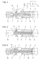
- Fig. 1 shows a partially sectioned shown pressure medium cylinder including parts of the measuring and control device and Fig. 2 and 3 show further exemplary embodiments of pressure medium cylinders according to the invention.
- the pressure medium cylinder 1 has an in in all illustrated embodiment variants sealed in the axial direction out of the cylinder 2, connected to the piston 3 and moving piston rod 4, which magnetized an elongated, differently Zones (symbolized only in FIG. 1 by the lines 5) has indicator element 6.
- This indicator element 6 or the differently magnetized zones are identified by an im Area of the lead-out 7 of the piston rod 4 in a bore 8 in the cylinder cover 9 (Figs. 1 and 2) or in a separately on the cylinder cover 9, e.g. in the form of a ring element, attached receiving element 18 (FIG. 3) arranged sensor device 10 for determination the piston position or the piston rod position can be scanned.
- FIG Line connection 11 to a processing unit 12 (for example ASIC) and to one Control unit 13 is drawn, which then via an only schematically indicated output 14 reports the respective piston or rod position in a manner not of further interest here or forwards corresponding commands.
- a processing unit 12 for example ASIC
- Control unit 13 is drawn, which then via an only schematically indicated output 14 reports the respective piston or rod position in a manner not of further interest here or forwards corresponding commands.
- the indicator element 6 is in one in the illustrated embodiments Piston rod 4 arranged essentially centrally arranged axial bore 15, wherein this axial bore 15 in the case of FIG. 1 as from the side of the rod head 16 and in 2 is designed as a blind hole extending from the side of the piston 3, which is closed on the open side by means of a fixing or sealing element 17. 3, the piston rod 4 is open on both sides, in the Inner bore 15 the correspondingly fixed and, if necessary, sealed indicator element 6 supporting tube formed, which on one side the piston 3 and on the other Side carries the rod head 16. There is an element 17 for sealing only on one side the bore 15 is drawn - of course, such an element could, if necessary also close the bore 15 on the rod side or the indicator element 6 completely fix and seal.
- the indicator element 6 with its spaced apart Zones of different magnetization have different known possibilities - it is only essential that these axially spaced zones make a clear determination allow the position of the piston rod 4 or at least some positions of the piston rod 4.
Landscapes
- Engineering & Computer Science (AREA)
- Physics & Mathematics (AREA)
- Fluid Mechanics (AREA)
- Mechanical Engineering (AREA)
- General Engineering & Computer Science (AREA)
- Actuator (AREA)
- Pistons, Piston Rings, And Cylinders (AREA)
- Measurement Of Length, Angles, Or The Like Using Electric Or Magnetic Means (AREA)
Abstract
Description
Die Erfindung betrifft einen Druckmittelzylinder mit einer in axialer Richtung abgedichtet aus dem Zylinder geführten, mit dem Kolben mitbewegten Kolbenstange, die ein längserstrecktes, unterschiedlich magnetisierte Zonen aufweisendes Indikatorelement trägt, das durch eine im Bereich der Herausführung der Kolbenstange angeordnete Sensoreinrichtung zur Ermittlung der Kolbenposition abtastbar ist.The invention relates to a pressure medium cylinder sealed in the axial direction out of the cylinder, with the piston moving piston rod, the one elongated indicator element with differently magnetized zones, by a sensor device arranged in the area of the lead-out of the piston rod can be scanned to determine the piston position.
Anordnungen der genannten Art sind beispielsweise aus EP 695 879 A1 oder WO 94/07037 bekannt und ermöglichen auf relativ einfache und genaue Weise eine Positionsbestimmung des Kolbens bzw. der Kolbenstange, wie sie für die Steuerung von Arbeitsabläufen, die Endlagenbestimmung und dergleichen Aufgaben erforderlich ist. Bei der erstgenannten bekannten Anordnung wird ein Magnetstreifen mit mehreren in Axialrichtung aufeinanderfolgend angeordneten, wechselpolig magnetisierten Zonen in einer seitlichen Nut bzw. Abflachung am Außenumfang der Kolbenstange angeordnet und mit einer Deckleiste versehen, die einen Schutz des Magnetstreifens und die Wiederherstellung einer abdichtbaren Außenkontur der Kolbenstange ermöglichen soll. Abgesehen von der relativ komplizierten Herstellung dieser Anordnung ist auch die tatsächliche Abdichtbarkeit der Kolbenstange an der Durchführung im Zylinderdeckel beeinträchtigt und das Widerstandsmoment der Kolbenstange geschwächt, was für viele Anwendungen nachteilig ist. Bei der zweitgenannten bekannten Anordnung sind Ringkörper mit unterschiedlicher Magnetisierung auf einem Kernstück der Kolbenstange angeordnet und außen mit einer zusätzlichen rohrförmigen Abdichtung versehen. Bei festigkeitsmäßig ausreichend dickem Kern der so aufgebauten Kolbenstange wird diese relativ voluminös, sodaß in dieser Schrift bereits vorgeschlagen wird, die beidseitig herausgeführte Kolbenstange auf der einen Seite für diese Indikatoreinrichtung und nur auf der anderen Seite für die eigentliche Kraftübertragung zu verwenden.Arrangements of the type mentioned are for example from EP 695 879 A1 or WO 94/07037 and enable a position determination in a relatively simple and precise manner the piston or the piston rod, as used for the control of work processes, end position determination and similar tasks are required. With the former Known arrangement is a magnetic strip with several in succession in the axial direction arranged, alternating pole magnetized zones in a lateral groove or Flattening arranged on the outer circumference of the piston rod and provided with a cover strip, which protect the magnetic stripe and restore a sealable Outer contour of the piston rod should allow. Aside from the relatively complicated Making this arrangement also depends on the actual sealability of the piston rod the implementation in the cylinder cover and affects the section modulus of the piston rod weakened, which is disadvantageous for many applications. In the second known Arrangement are ring bodies with different magnetization on a core the piston rod and the outside with an additional tubular seal Mistake. With a sufficiently thick core of the piston rod constructed in this way this becomes relatively voluminous, so that this document already proposes that Piston rod led out on both sides on one side for this indicator device and only to be used on the other side for the actual power transmission.
Aufgabe der vorliegenden Erfindung ist es, einen Druckmittelzylinder der eingangs genannten Art so zu verbessern, daß die angesprochenen Nachteile der bekannten derartigen Anordnungen vermieden werden und daß insbesonders eine einfach herzustellende, leicht abzudichtende und festigkeitsmäßig ausreichende Konstruktion möglich wird.The object of the present invention is to provide a pressure medium cylinder mentioned type to improve so that the disadvantages of the known such Arrangements are avoided and in particular that an easy to manufacture easily sealed and strength-sufficient construction is possible.
Diese Aufgabe wird gemäß der vorliegenden Erfindung bei einer Anordnung der eingangs genannten Art dadurch gelöst, daß die Kolbenstange eine im wesentlichen zentral angeordnete Axialbohrung aufweist, in der das Indikatorelement angeordnet ist. Durch diese zentrale Bohrung wird das Widerstandsmoment der Kolbenstange nur sehr wenig geschwächt, sodaß gegenüber einer rein stangenartig vollen Kolbenstange in der Praxis keine oder nur eine sehr geringe Durchmesservergrößerung zur Aufnahme des Indikatorelementes erforderlich ist. Außerdem ist die Herstellung einer derartigen Kolbenstange sehr viel einfacher als bei den eingangs beschriebenen Anordnungen, wobei in vorteilhafter Weise die abzudichtende Außenfläche der Kolbenstange völlig unbeeinflußt bleibt.This object is achieved according to the present invention in an arrangement of the beginning mentioned type in that the piston rod is a substantially central has arranged axial bore in which the indicator element is arranged. Through this in the central bore, the moment of resistance of the piston rod is weakened very little, so that compared to a purely rod-like full piston rod in practice none or only a very small increase in diameter to accommodate the indicator element is required. In addition, the manufacture of such a piston rod is much easier than in the arrangements described in the introduction, the sealing to be sealed in an advantageous manner The outer surface of the piston rod remains completely unaffected.
Die das fixierte und gegebenenfalls abgedichtete Indikatorelement aufnehmende Axialbohrung der Kolbenstange ist in vorteilhafter Ausgestaltung der Erfindung als von der Seite des Kolbens bzw. der Seite des Stangenkopfes ausgehende Sacklochbohrung ausgeführt, was eine einfache Herstellung bei gleichzeitig problemloser Abdichtung nach außen bzw. innen sicherstellt.The axial bore receiving the fixed and possibly sealed indicator element the piston rod is in an advantageous embodiment of the invention as from the side blind hole originating from the piston or the side of the rod head, what a simple manufacture with a problem-free sealing to the outside or ensures inside.
Nach einer anderen bevorzugten Ausgestaltung der Erfindung kann die Kolbenstange aber auch als beidseitig offenes, in der Innenbohrung das fixierte und abgedichtete Indikatorelement tragendes Rohr ausgebildet sein, welches auf der einen Seite den Kolben und auf der anderen Seite den Stangenkopf trägt. Entsprechende Rohre mit geeigneten Dimensionen und Festigkeiten sind Massenware, sodaß bei dieser Ausgestaltung die Herstellung des Druckmittelzylinders insgesamt weiter vereinfacht und kostengünstiger wird.According to another preferred embodiment of the invention, the piston rod but also as an open indicator on both sides, the fixed and sealed indicator element in the inner bore be formed supporting tube which on one side the piston and the other side carries the rod head. Appropriate pipes with suitable dimensions and strengths are mass-produced goods, so that the production of the Total pressure cylinder is further simplified and cheaper.
Die Sensoreinrichtung ist nach einer weiters bevorzugten Ausgestaltung der Erfindung in einer Bohrung im Zylinderdeckel nahe der Kolbenstangendurchführung angeordnet, was eine konstruktiv einfache Lösung ermöglicht und eine ausreichende Empfindlichkeit der Positionsbestimmung sicherstellt. According to a further preferred embodiment of the invention, the sensor device arranged in a hole in the cylinder cover near the piston rod bushing, what enables a structurally simple solution and sufficient sensitivity of the position determination ensures.
Gemäß einer weiteren vorteilhaften Ausführung der Erfindung ist die Sensoreinrichtung in einem nahe der Kolbenstangendurchführung am Zylinderdeckel angebrachten, separaten Aufnahmeelement angeordnet, was auch die einfache Nachrüstung konventioneller Zylinder ermöglicht.According to a further advantageous embodiment of the invention, the sensor device in a separate one near the piston rod bushing on the cylinder cover Receiving element arranged, which is also the simple retrofitting conventional Cylinder allows.
Die Erfindung wird im folgenden noch anhand der in der Zeichnung schematisch dargestellten Ausführungsbeispiele näher erläutert. Fig. 1 zeigt dabei einen teilweise geschnitten dargestellten Druckmittelzylinder samt Teilen der Meß- und Steuereinrichtung und Fig. 2 und 3 zeigen weitere Ausführungsbeispiele von erfindungsgemäßen Druckmittelzylindern.The invention is illustrated below with reference to that shown schematically in the drawing Exemplary embodiments explained in more detail. Fig. 1 shows a partially sectioned shown pressure medium cylinder including parts of the measuring and control device and Fig. 2 and 3 show further exemplary embodiments of pressure medium cylinders according to the invention.
Der Druckmittelzylinder 1 weist in allen dargestellten Ausführungsvarianten eine in
axialer Richtung abgedichtet aus dem Zylinder 2 geführte, mit dem Kolben 3 verbundene
und mitbewegte Kolbenstange 4 auf, die ein längserstrecktes, unterschiedlich magnetisierte
Zonen (nur in Fig. 1 symbolisiert durch die Striche 5) aufweisendes Indikatorelement 6 trägt.
Dieses Indikatorelement 6 bzw. die unterschiedlich magnetisierten Zonen sind durch eine im
Bereich der Herausführung 7 der Kolbenstange 4 in einer Bohrung 8 im Zylinderdeckel 9
(Fig. 1 und 2) bzw. in einem separat am Zylinderdeckel 9, z.B. in Form eines Ringelementes,
angebrachten Aufnahmeelement 18 (Fig. 3) angeordnete Sensoreinrichtung 10 zur Ermittlung
der Kolbenposition bzw. der Kolbenstangenposition abtastbar. Dazu ist in Fig. 1 eine
Leitungsverbindung 11 zu einer Aufbereitungseinheit 12 (beispielsweise ASIC) und zu einem
Steuergerät 13 eingezeichnet, das dann über einen nur schematisch angedeuteten Ausgang
14 auf hier nicht weiter interessante Weise die jeweilige Kolben- bzw. Stangenposition weitermeldet
bzw. entsprechende Befehle weiterleitet.The
Das Indikatorelement 6 ist in allen dargestellten Ausführungsformen in einer in der
Kolbenstange 4 im wesentlichen zentral angeordneten Axialbohrung 15 angeordnet, wobei
diese Axialbohrung 15 im Falle der Fig. 1 als von der Seite des Stangenkopfes 16 und im
Falle der Fig. 2 als von der Seite des Kolbens 3 ausgehende Sacklochbohrung ausgeführt ist,
welche auf der offenen Seite mittels eines Fixier- bzw. Dichtelementes 17 abgeschlossen ist.
Im Falle der Ausführung nach Fig. 3 ist die Kolbenstange 4 als beidseitig offenes, in der
Innenbohrung 15 das entsprechend fixierte und bedarfsweise abgedichtete Indikatorelement
6 tragendes Rohr ausgebildet, welches auf der einen Seite den Kolben 3 und auf der anderen
Seite den Stangenkopf 16 trägt. Es ist hier nur auf einer Seite ein Element 17 zur Abdichtung
der Bohrung 15 eingezeichnet - bedarfsweise könnte aber natürlich ein derartiges Element
auch auf der Stangenseite die Bohrung 15 abschließen bzw. das Indikatorelement 6 vollständig
fixieren und abdichten.The
Für die konkrete Ausführung des Indikatorelementes 6 mit seinen beabstandeten
Zonen unterschiedlicher Magnetisierung gibt es verschiedenste bekannte Möglichkeiten -
wesentlich ist nur, daß diese axial beabstandet liegenden Zonen eine eindeutige Feststellung
der Position der Kolbenstange 4 bzw. zumindest einiger Positionen der Kolbenstange 4 erlauben.For the specific implementation of the
Claims (5)
Applications Claiming Priority (2)
| Application Number | Priority Date | Filing Date | Title |
|---|---|---|---|
| AT21162000 | 2000-12-20 | ||
| AT21162000 | 2000-12-20 |
Publications (2)
| Publication Number | Publication Date |
|---|---|
| EP1217221A2 true EP1217221A2 (en) | 2002-06-26 |
| EP1217221A3 EP1217221A3 (en) | 2004-03-17 |
Family
ID=3689890
Family Applications (1)
| Application Number | Title | Priority Date | Filing Date |
|---|---|---|---|
| EP01890344A Withdrawn EP1217221A3 (en) | 2000-12-20 | 2001-12-19 | Fluid power cylinder |
Country Status (1)
| Country | Link |
|---|---|
| EP (1) | EP1217221A3 (en) |
Cited By (3)
| Publication number | Priority date | Publication date | Assignee | Title |
|---|---|---|---|---|
| US6863334B2 (en) * | 2001-06-01 | 2005-03-08 | Bayerische Motoren Werke Aktiengesellschaft | System for opening and closing a folding top or displaceable vehicle roof on a convertible vehicle |
| WO2007110095A1 (en) * | 2006-03-28 | 2007-10-04 | Norgren Gmbh | Displacement sensor for a rod |
| EP3293402A1 (en) * | 2016-09-07 | 2018-03-14 | ELGO-Electronic GmbH & Co. KG | Piston-cylinder device and use of same |
Citations (2)
| Publication number | Priority date | Publication date | Assignee | Title |
|---|---|---|---|---|
| WO1994007037A1 (en) | 1992-09-23 | 1994-03-31 | Ab Rexroth Mecman | Positioning device for fluid cylinder |
| EP0695879A1 (en) | 1994-08-02 | 1996-02-07 | Festo KG | Power cylinder |
Family Cites Families (4)
| Publication number | Priority date | Publication date | Assignee | Title |
|---|---|---|---|---|
| DE3324584A1 (en) * | 1982-07-07 | 1984-01-12 | Linde Ag, 6200 Wiesbaden | Device for detecting a relative displacement position |
| US4717874A (en) * | 1984-02-10 | 1988-01-05 | Kabushiki Kaisha Sg | Reluctance type linear position detection device |
| JPS635201A (en) * | 1986-06-25 | 1988-01-11 | Denki Kagaku Kogyo Kk | Apparatus for detecting linear displacement |
| DE3734547A1 (en) * | 1987-10-13 | 1989-05-03 | Festo Kg | PISTON CYLINDER AGGREGATE |
-
2001
- 2001-12-19 EP EP01890344A patent/EP1217221A3/en not_active Withdrawn
Patent Citations (2)
| Publication number | Priority date | Publication date | Assignee | Title |
|---|---|---|---|---|
| WO1994007037A1 (en) | 1992-09-23 | 1994-03-31 | Ab Rexroth Mecman | Positioning device for fluid cylinder |
| EP0695879A1 (en) | 1994-08-02 | 1996-02-07 | Festo KG | Power cylinder |
Cited By (5)
| Publication number | Priority date | Publication date | Assignee | Title |
|---|---|---|---|---|
| US6863334B2 (en) * | 2001-06-01 | 2005-03-08 | Bayerische Motoren Werke Aktiengesellschaft | System for opening and closing a folding top or displaceable vehicle roof on a convertible vehicle |
| WO2007110095A1 (en) * | 2006-03-28 | 2007-10-04 | Norgren Gmbh | Displacement sensor for a rod |
| CN101427106B (en) * | 2006-03-28 | 2012-02-22 | 诺格伦有限责任公司 | Displacement sensor for a rod |
| US8237430B2 (en) | 2006-03-28 | 2012-08-07 | Norgren Gmbh | Displacement sensor for a rod |
| EP3293402A1 (en) * | 2016-09-07 | 2018-03-14 | ELGO-Electronic GmbH & Co. KG | Piston-cylinder device and use of same |
Also Published As
| Publication number | Publication date |
|---|---|
| EP1217221A3 (en) | 2004-03-17 |
Similar Documents
| Publication | Publication Date | Title |
|---|---|---|
| EP3840968B1 (en) | Roll stabilizer | |
| DE102015102233B4 (en) | Position sensor and thus created measuring arrangement | |
| EP0097868B1 (en) | Door closer with an adjustable closing force | |
| EP1489385B1 (en) | Device for detecting the axial position of a first part which is moveable relative to a second part | |
| DE102014019546B3 (en) | Spring body for a load cell, such as torque and / or traction / pressure cell | |
| DE102006049724A1 (en) | Valve arrangement with position sensor | |
| DE102016121671B3 (en) | Position sensor and positioner with position sensor | |
| DE102009041159B4 (en) | Displacement sensor unit and arrangement with the displacement sensor unit | |
| DE3319522C2 (en) | Pressure fluid operated piston-cylinder unit | |
| DE102008062521A1 (en) | Flow sensor for fluid media | |
| DE102006045827A1 (en) | Axially displaceable component, in particular in a motor vehicle engine or transmission | |
| CH688419A5 (en) | Safety valve for a pressure cooker. | |
| WO2010088931A1 (en) | Piston-cylinder assembly having integrated measuring device | |
| DE10200609A1 (en) | Electrically assisted power steering for motor vehicles | |
| WO2000073756A1 (en) | Sensor, in particular, a magnetostrictive or magnetoelastic sensor | |
| DE102005060674C5 (en) | Position sensor in rod construction and procedure for exchange | |
| EP1217221A2 (en) | Fluid power cylinder | |
| DE202018103775U1 (en) | Performance measurement arrangement | |
| EP1253329B1 (en) | Pressure fluid actuator with means for preventing rotation | |
| DE10152178A1 (en) | Pressure cylinder with a displaceable sensor for the detection of the piston position | |
| CH704909A2 (en) | Knitting cylinders with sensor. | |
| EP1070856B1 (en) | Piston position indicator | |
| EP3611088B1 (en) | Crank and bicycle comprising same | |
| DE3510252A1 (en) | Position transmitter for a hydraulic working cylinder | |
| DE102004060920B4 (en) | Bar magnet for measuring device, measuring device |
Legal Events
| Date | Code | Title | Description |
|---|---|---|---|
| PUAI | Public reference made under article 153(3) epc to a published international application that has entered the european phase |
Free format text: ORIGINAL CODE: 0009012 |
|
| AK | Designated contracting states |
Kind code of ref document: A2 Designated state(s): AT BE CH CY DE DK ES FI FR GB GR IE IT LI LU MC NL PT SE TR |
|
| AX | Request for extension of the european patent |
Free format text: AL;LT;LV;MK;RO;SI |
|
| PUAL | Search report despatched |
Free format text: ORIGINAL CODE: 0009013 |
|
| AK | Designated contracting states |
Kind code of ref document: A3 Designated state(s): AT BE CH CY DE DK ES FI FR GB GR IE IT LI LU MC NL PT SE TR |
|
| AX | Request for extension of the european patent |
Extension state: AL LT LV MK RO SI |
|
| 17P | Request for examination filed |
Effective date: 20040408 |
|
| 17Q | First examination report despatched |
Effective date: 20040805 |
|
| AKX | Designation fees paid |
Designated state(s): DE FR SE |
|
| STAA | Information on the status of an ep patent application or granted ep patent |
Free format text: STATUS: THE APPLICATION IS DEEMED TO BE WITHDRAWN |
|
| 18D | Application deemed to be withdrawn |
Effective date: 20041216 |