EP1216331B1 - Tank - Google Patents
Tank Download PDFInfo
- Publication number
- EP1216331B1 EP1216331B1 EP00960931A EP00960931A EP1216331B1 EP 1216331 B1 EP1216331 B1 EP 1216331B1 EP 00960931 A EP00960931 A EP 00960931A EP 00960931 A EP00960931 A EP 00960931A EP 1216331 B1 EP1216331 B1 EP 1216331B1
- Authority
- EP
- European Patent Office
- Prior art keywords
- tank
- tank according
- torus
- fitting
- partitions
- Prior art date
- Legal status (The legal status is an assumption and is not a legal conclusion. Google has not performed a legal analysis and makes no representation as to the accuracy of the status listed.)
- Expired - Lifetime
Links
Images

Classifications
-
- E—FIXED CONSTRUCTIONS
- E03—WATER SUPPLY; SEWERAGE
- E03F—SEWERS; CESSPOOLS
- E03F11/00—Cesspools
-
- B—PERFORMING OPERATIONS; TRANSPORTING
- B65—CONVEYING; PACKING; STORING; HANDLING THIN OR FILAMENTARY MATERIAL
- B65D—CONTAINERS FOR STORAGE OR TRANSPORT OF ARTICLES OR MATERIALS, e.g. BAGS, BARRELS, BOTTLES, BOXES, CANS, CARTONS, CRATES, DRUMS, JARS, TANKS, HOPPERS, FORWARDING CONTAINERS; ACCESSORIES, CLOSURES, OR FITTINGS THEREFOR; PACKAGING ELEMENTS; PACKAGES
- B65D88/00—Large containers
- B65D88/02—Large containers rigid
- B65D88/04—Large containers rigid spherical
Definitions
- the invention relates to a tank according to the preamble of claim 1.
- Tanks such as sewage holding tanks, usually have a cylindrical or spherical form.
- the prior art also shows a sewage holding tank in the shape of a ball with spherical indentations removed from opposite sides thereof. It is rather difficult to provide a cylindrical sewage holding tank with sufficient strength properties. On the other hand, it is difficult to transport spherical sewage holding tanks, which require for example separate legs or some other corresponding supports during the transportation in order not to fall over. Further, a problem that is common to all sewage holding tanks is that their depth of installation is rather great, i.e. installation of the tanks requires the excavation of quite a deep pit. Also, it is rather difficult to anchor especially plastic sewage holding tanks in place so that they will not be moved by soil frost or ground water.
- US-A-5 628 420 discloses a rollable container.
- the container comprises a hollow enclosed substantially cylindrical rigid body.
- the body is provided with an elongate passageway extending through the body along the cylindrical axis thereof.
- the container is provided with a handling device for retaining the container rotatably about the cylindrical axis.
- US-A-4 475 662 discloses a toroidal pressure vessel of compound material.
- the pressure vessel has an inner core, which is very lightweight and made of rubber for example.
- the core has an inner toroidal shape and an outer cylindrical contour.
- a first plurality of filament windings is wrapped in a meridian direction around the core and an additional plurality of filament windings is wrapped equatorially on the vessel around the cylindrical contour.
- the purpose of the present invention is to provide a tank where at least some of the aforementioned disadvantages can be avoided.
- the tank according to the invention is characterized by the characterizing part of claim 1.
- the basic idea of the invention is that the inner surface of the tank is substantially torus-shaped.
- the idea of a preferred embodiment is that also the outer surface of the tank is substantially torus-shaped.
- the surface of the tank is provided with ribs that reinforce the tank structure.
- the idea of a third preferred embodiment is that the ribs provided on the surface of the tank are made such that grooves are formed on the outer surface of the tank.
- the idea of a fourth preferred embodiment is that the tank is provided with at least one preformed opening in order that a separate pipe fitting can be arranged to be used as an inlet/outlet fitting or as a rising pipe.
- the idea of a fifth preferred embodiment is that the tank is converted into a septic tank through the installation of partitions inside the torus-shaped tank.
- An advantage of the invention is that when the tank is laid in the ground, it does not require a very deep pit.
- the tank of the invention does not require as deep a pit as is required for the same volume in a spherical or cylindrical shape.
- the structure of the tank is rather strong and it can be made such that it does not contain long horizontal surfaces but, for example, mainly curved surfaces. Due to the curved surfaces the loads stressing the structure are distributed advantageously with respect to the strength properties.
- the tank can be anchored to the ground rather easily if the outer surface of the tank is also torus-shaped, since the anchoring can be implemented utilizing a hole that is situated in the middle of the tank outside it.
- the tank remains in an upright position without the need to use separate legs or other special arrangements to support the tank.
- the structure can be strengthened further.
- the grooves can be utilized as guides for ropes that anchor the tank in place.
- a separate pipe fitting is used as an inlet/outlet fitting or as a rising pipe, a pipe can be installed and fastened from any direction of the tank. installation of partitions in the torus-shaped tank provides a compact septic tank in a simple and easy manner.
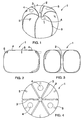
- FIG. 1 shows a tank 1, which is made of a plastic material, for example a polyolefin, such as polyethylene PE, polypropylene PP or crosslinked polyethylene PEX.
- the tank 1 shown in the figure can be formed as a single piece for example through rotational casting.
- the tank 1 can be used as a fluid tank for storing for example water or, for example, a sewage holding tank for storing waste water or some other waste liquid. Further, the tank can also be used as a septic tank or a part thereof.
- the tank is thus pressureless and intended to be used buried in the ground.
- the inner surface of the tank 1 is substantially torus-shaped so that the height of the tank is smaller than the height of a spherical tank for the same volume.
- substantially torus-shaped means that the inner surface of the tank 1 has a similar shape as a surface formed by a closed curve which has revolved around the axis on the same level. Further, the definition “substantially torus-shaped” means that the closed curve can be for example circular but it can also be oval and it may comprise straight sections in the upper and lower parts thereof and on each side, and the curve may even be rectangular, as shown in greater detail in Figures 2 and 3, and 9 to 12.
- the outer surface of the tank 1 is also substantially torus-shaped, and there is a hole 2 situated outside the container of the tank 1 intended for storing liquid, the hole being also positioned in the middle of the tank 1. Therefore the walls of the tank 1 do not comprise long unsupported horizontal sections and the walls can be made rather thin.
- the walls of the tank 1 can be provided with ribs 3 that support the walls.
- the ribs 3 are preferably formed such that the wall of the tank 1 is shaped so that it is provided with grooves which are directed inwards.
- the grooves formed by the ribs 3, and the hole 2 of the tank 1 can be utilized when the tank 1 is being anchored in place.
- the number and shape of the ribs 3 may vary according to the needs.
- the tank 1 can be laid in the ground, but if desired, it can also be installed indoors. Despite the rather great volume of the tank 1 the tank is not very high, wherefore it does not require a very deep pit in order to be installed.
- the ribs 3 are not shown in Figures 2 and 3.
- the tank 1 is provided with three preformed openings 4, at least one of which is opened when the tank 1 is taken into use. There must be at least one preformed opening 4 and the number thereof may vary depending on the size and intended use of the tank 1.
- a separate inlet or outlet fitting or a rising pipe is to be connected to the opened preformed opening 4.
- the tank 1 can also be provided with a desired number of fixed fittings.
- the upper part of the tank 1 is also provided with anchor fasteners 5, which can be used to anchor the tank 1 in place.
- the anchor fasteners 5 can also be utilized as lifting lugs so that the tank 1 can be fastened easily to a lifting apparatus.
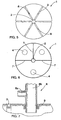
- the tank 1 is shown in Figure 4 in a top view and in Figure 5 in a bottom view.
- Figure 5 shows recesses 6 formed in the ribs 3 and placed at the bottom of the tank 1 to ensure that a segment between two ribs 3 will not contain any liquid after the tank 1 has been emptied.
- Figure 6 shows an arrangement where the tank 1 is converted by means of partitions 7 into a septic tank with three chambers.
- the septic tank comprises separate chambers through which waste water flows. Water is arranged to flow as slowly as possible from the upper part of a preceding chamber to the next chamber in order that the greatest particles in each chamber have time to fall to the bottom of the chamber to form precipitate. When the waste water has passed through the last chamber, all the solids that might interfere with the subsequent cleaning have been separated from the water.
- the volume of the first chamber is most preferably about half of the total volume of the tank 1.
- a preformed opening 4 provided in connection with each chamber is opened and a rising pipe is placed in the opened preformed opening for the purpose of emptying the chamber.
- the first chamber can be provided, for example, with a fitting 8 shown in Figure 7, the horizontal part 8a of the fitting 8 forming the inlet fitting and the vertical part 8b forming the rising pipe intended for emptying.
- the upper part of the partition 7 comprises one or several holes via which the waste liquid is able to flow to the next chamber.
- the last chamber in the direction of flow of the waste liquid is provided with an outlet fitting directed sideways, as shown for example in Figure 2 by a broken line.
- Figure 7 shows a separate fitting 8, which is placed in connection with the opened preformed opening 4, and which may be an inlet fitting or an outlet fitting or a rising pipe used for emptying.
- the fitting 8 is sealed to the tank 1 by seals 9.
- the use of a separate fitting 8 enables, for example, the fastening of an inlet pipe to the tank 1 from any direction. Therefore, when the tank 1 is being laid in the ground, the direction of the inlet pipe does not have to be known exactly and the position of the tank 1 can thus be selected rather freely during the installation.
- the diameter of the preformed opening 4 and the fitting 8 can vary depending on the needs.
- FIG 8 shows a tank 1 comprising one partition 7.
- the tank 1 also comprises an inlet fitting 10 and an outlet fitting 11.
- the partition 7 most preferably extends continuously from the bottom to the top. Therefore the liquid flowing into the tank 1 enters through the inlet fitting 10 and is discharged through the outlet fitting 11, and it flows in the tank 1 in the manner shown by arrow A and it settles in the tank 1. Therefore the tank 1 operates as a settlement tank in the embodiment shown in Figure 8.
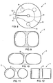
- Figure 9 shows a tank 1 the outer surface of which resembles a flattened sphere. However, since the inner surface of the tank 1 is substantially torus-shaped, the tank 1 comprises in the middle a supporting section, wherefore the tank 1 does not comprise long horizontal unsupported parts. For example compared to the arrangement shown in Figure 3, the solution of Figure 9 does not comprise a hole 2 situated in the middle of the tank outside it, but the hole is replaced in the tank of Figure 9 with the supporting section.
- the tank 1 of Figure 9 can be made, for example, by manufacturing through injection molding two tank halves that are joined.
- Figure 11 shows a tank where the outer and inner surfaces are substantially torus-shaped, and the torus surfaces are formed by circles that have revolved around the axis on the same level.
- the torus surfaces of the tank shown in Figure 10 are formed by ovals which have revolved around the axis on the same level. Also in the arrangement of Figure 3 the torus surfaces are formed by ovals, but therein the area of the horizontal surface is smaller than the area of the vertical surface, whereas in Figure 10 the area of the horizontal surface is, in turn, greater than the area of the vertical surface.
- the torus surfaces of the tank are formed by rectangles which have revolved around the axis on the same level. If desired, the rectangles may have rounded comers.
- Figure 13 shows a tank 1, which is provided with a rising pipe 12 substantially in the middle of the tank 1.
- the diameter of the rising pipe 12 is greater than the diameter of a hole 2 or, for example, the diameter of the supporting section of the tank shown in Figure 9.
- the tank 1 comprises openings 13, so that the interior of the tank 1 is connected to the rising pipe 12.
- the hole 2 is provided with a bottom 14. Further, it is possible to provide one or more openings in the tank 1, for example in the lower part thereof, as shown with a broken line in Figure 13.
- Figure 14 shows a detail of a wall of a tank, the wall consisting of several layers.
- the innermost layer 15a is preferably lighter than the other layers. This facilitates checking and maintenance of the tank. For example, less light is needed inside the tank during maintenance and checking when the innermost layer 15a is light compared to a situation where the innermost layer 15a is dark.
- one of the layers can be made of closed cell polyolefin. Closed cell polyolefin acts as heat insulation, providing thus a thermally insulated tank.
- the middle layer 15b is preferably made of closed cell polyolefin, whereas the innermost layer 15a and the outermost layer 15c are made of normal polyolefin.
- the tank 1 can be provided with a spirit level with which the horizontal position of the tank 1 can be checked easily during the installation.
- the tank 1 is typically mounted in a horizontal position as accurately as possible in order to prevent for example the formation of air pockets in the tank 1.
- the tank 1 can also be installed in some other position than horizontally.
- the tank 1 can be provided with an alarm, which identifies the boundary between air and water and indicates that the tank is full.
- the alarm indicating the filling of the tank is most preferably installed in a rising pipe so that it can be easily replaced and handled in connection with breakage and/or maintenance.
Landscapes
- Engineering & Computer Science (AREA)
- Health & Medical Sciences (AREA)
- Life Sciences & Earth Sciences (AREA)
- Hydrology & Water Resources (AREA)
- Public Health (AREA)
- Water Supply & Treatment (AREA)
- Mechanical Engineering (AREA)
- Electrical Discharge Machining, Electrochemical Machining, And Combined Machining (AREA)
- Treatment Of Biological Wastes In General (AREA)
- Glass Compositions (AREA)
Applications Claiming Priority (3)
| Application Number | Priority Date | Filing Date | Title |
|---|---|---|---|
| FI992114 | 1999-09-30 | ||
| FI992114A FI19992114A (fi) | 1999-09-30 | 1999-09-30 | Säiliö |
| PCT/IB2000/001392 WO2001023682A1 (en) | 1999-09-30 | 2000-09-28 | Tank |
Publications (2)
| Publication Number | Publication Date |
|---|---|
| EP1216331A1 EP1216331A1 (en) | 2002-06-26 |
| EP1216331B1 true EP1216331B1 (en) | 2004-10-20 |
Family
ID=8555393
Family Applications (1)
| Application Number | Title | Priority Date | Filing Date |
|---|---|---|---|
| EP00960931A Expired - Lifetime EP1216331B1 (en) | 1999-09-30 | 2000-09-28 | Tank |
Country Status (10)
| Country | Link |
|---|---|
| EP (1) | EP1216331B1 (et) |
| AT (1) | ATE280283T1 (et) |
| AU (1) | AU7308100A (et) |
| DE (2) | DE60015166T2 (et) |
| EE (1) | EE04569B1 (et) |
| FI (1) | FI19992114A (et) |
| NO (1) | NO335605B1 (et) |
| PL (1) | PL354084A1 (et) |
| RU (1) | RU2261308C2 (et) |
| WO (1) | WO2001023682A1 (et) |
Cited By (1)
| Publication number | Priority date | Publication date | Assignee | Title |
|---|---|---|---|---|
| WO2015031699A3 (en) * | 2013-08-28 | 2015-04-23 | Moon Express, Inc. | System and method for multi-role planetary lander and ascent spacecraft |
Families Citing this family (6)
| Publication number | Priority date | Publication date | Assignee | Title |
|---|---|---|---|---|
| DE10237299A1 (de) * | 2002-08-14 | 2004-03-04 | Richter, Günter | Kunststoffbehälter zum Sammeln von Regenwasser |
| FI20021571A (fi) | 2002-09-03 | 2004-03-04 | Uponor Innovation Ab | Säiliö |
| AU2005203085C1 (en) * | 2005-05-16 | 2011-09-01 | Duraplas Industries Pty. Limited | Improved Storage Tank and Method of Installation |
| EP1902975A1 (en) * | 2006-09-22 | 2008-03-26 | Ecologia Soluzione Ambiente S.p.A. | A series of modular elements for forming a self-supporting waste liquid tray, and a process for assembly thereof |
| IT1394373B1 (it) * | 2009-06-22 | 2012-06-15 | Rototec S P A | Serbatoio idraulico da interro |
| RU168597U1 (ru) * | 2014-12-05 | 2017-02-09 | Общество с ограниченной ответственностью "Туборус" | Многотоннажный резервуар для хранения воды |
Family Cites Families (8)
| Publication number | Priority date | Publication date | Assignee | Title |
|---|---|---|---|---|
| US3612329A (en) * | 1969-09-25 | 1971-10-12 | Union Tank Car Co | Tank |
| US3784012A (en) * | 1972-03-31 | 1974-01-08 | H Carlson | Septic tank construction |
| FR2487305A1 (fr) * | 1980-07-25 | 1982-01-29 | Poulain Edgard | Cuveries a partir d'elements modulaires |
| DE3147867C1 (de) * | 1981-12-03 | 1983-07-07 | Messerschmitt-Bölkow-Blohm GmbH, 8000 München | Torusfoermiger Druckbehaelter aus Verbundmaterial |
| US4790472A (en) * | 1984-10-11 | 1988-12-13 | Allied Signal Inc. | Methods for manufacturing a toroidal pressure vessel |
| US4824287A (en) * | 1988-02-19 | 1989-04-25 | Tracy Lawrence M | Septic system |
| BR9302938A (pt) * | 1992-07-22 | 1994-02-22 | Pieter Johannes Hendrikse | Recipiente e metodo de fabricacao de recipiente por processo de moldagem |
| GB9523089D0 (en) * | 1995-09-23 | 1996-01-10 | Secr Defence | Gas containment apparatus |
-
1999
- 1999-09-30 FI FI992114A patent/FI19992114A/fi not_active Application Discontinuation
-
2000
- 2000-09-28 EP EP00960931A patent/EP1216331B1/en not_active Expired - Lifetime
- 2000-09-28 DE DE60015166T patent/DE60015166T2/de not_active Expired - Lifetime
- 2000-09-28 PL PL00354084A patent/PL354084A1/xx unknown
- 2000-09-28 AU AU73081/00A patent/AU7308100A/en not_active Abandoned
- 2000-09-28 WO PCT/IB2000/001392 patent/WO2001023682A1/en active IP Right Grant
- 2000-09-28 EE EEP200200089A patent/EE04569B1/et not_active IP Right Cessation
- 2000-09-28 RU RU2002111566/03A patent/RU2261308C2/ru not_active IP Right Cessation
- 2000-09-28 DE DE1216331T patent/DE1216331T1/de active Pending
- 2000-09-28 AT AT00960931T patent/ATE280283T1/de not_active IP Right Cessation
-
2002
- 2002-03-19 NO NO20021363A patent/NO335605B1/no not_active IP Right Cessation
Cited By (1)
| Publication number | Priority date | Publication date | Assignee | Title |
|---|---|---|---|---|
| WO2015031699A3 (en) * | 2013-08-28 | 2015-04-23 | Moon Express, Inc. | System and method for multi-role planetary lander and ascent spacecraft |
Also Published As
| Publication number | Publication date |
|---|---|
| EE200200089A (et) | 2003-04-15 |
| RU2261308C2 (ru) | 2005-09-27 |
| FI19992114A (fi) | 2001-03-30 |
| NO20021363L (no) | 2002-03-19 |
| ATE280283T1 (de) | 2004-11-15 |
| EP1216331A1 (en) | 2002-06-26 |
| WO2001023682A1 (en) | 2001-04-05 |
| NO20021363D0 (no) | 2002-03-19 |
| DE60015166D1 (en) | 2004-11-25 |
| NO335605B1 (no) | 2015-01-12 |
| AU7308100A (en) | 2001-04-30 |
| EE04569B1 (et) | 2005-12-15 |
| DE60015166T2 (de) | 2006-02-02 |
| PL354084A1 (en) | 2003-12-29 |
| DE1216331T1 (de) | 2003-09-18 |
Similar Documents
| Publication | Publication Date | Title |
|---|---|---|
| US10894660B2 (en) | Underwater energy storage system and power station powered therewith | |
| US6318581B1 (en) | Discharge outlet for double wall containment tank assembly | |
| US6328890B1 (en) | Septic waste treatment system | |
| US3429128A (en) | Offshore storage structure | |
| RU2005115479A (ru) | Хранилище, расположенное на морском дне | |
| EP1216331B1 (en) | Tank | |
| KR890012892A (ko) | 부패 시스템 | |
| WO2001064309A1 (en) | Residential septic tank | |
| US4987922A (en) | Storage tank for two fluids of different density | |
| US4884709A (en) | Underground storage tank | |
| US6474496B1 (en) | Containment tank assembly | |
| CN1072172C (zh) | 用于货物集装箱的自动排水装置 | |
| GB2066095A (en) | A device for recovery of fluids from a subaqueous leak | |
| US6012871A (en) | Septic tank system and distribution device suitable for use in sloping terrain | |
| US7207284B2 (en) | Tank installation for the storage of liquids | |
| US3422628A (en) | Offshore storage tank system | |
| RU2002111566A (ru) | Резервуар | |
| US7341660B1 (en) | Unitary three stage wastewater treatment system | |
| RU151535U1 (ru) | Емкость горизонтальная | |
| CA2543235C (en) | Tank mixing system and valve therefor | |
| JP4744045B2 (ja) | 空気弁 | |
| JP3017171B2 (ja) | 有水式のガスホルダー | |
| JP4082527B2 (ja) | 内面螺旋案内路付き管 | |
| AU673123B2 (en) | Anchoring reservoirs in the ground | |
| GB2222612A (en) | Septic tank |
Legal Events
| Date | Code | Title | Description |
|---|---|---|---|
| PUAI | Public reference made under article 153(3) epc to a published international application that has entered the european phase |
Free format text: ORIGINAL CODE: 0009012 |
|
| 17P | Request for examination filed |
Effective date: 20020308 |
|
| AK | Designated contracting states |
Kind code of ref document: A1 Designated state(s): AT BE CH CY DE DK ES FI FR GB GR IE IT LI LU MC NL PT SE |
|
| AX | Request for extension of the european patent |
Free format text: AL PAYMENT 20020308;LT PAYMENT 20020308;LV PAYMENT 20020308;MK PAYMENT 20020308;RO PAYMENT 20020308;SI PAYMENT 20020308 |
|
| 17Q | First examination report despatched |
Effective date: 20030424 |
|
| DET | De: translation of patent claims | ||
| GRAP | Despatch of communication of intention to grant a patent |
Free format text: ORIGINAL CODE: EPIDOSNIGR1 |
|
| GRAS | Grant fee paid |
Free format text: ORIGINAL CODE: EPIDOSNIGR3 |
|
| GRAA | (expected) grant |
Free format text: ORIGINAL CODE: 0009210 |
|
| AK | Designated contracting states |
Kind code of ref document: B1 Designated state(s): AT BE CH CY DE DK ES FI FR GB GR IE IT LI LU MC NL PT SE |
|
| AX | Request for extension of the european patent |
Extension state: AL LT LV MK RO SI |
|
| PG25 | Lapsed in a contracting state [announced via postgrant information from national office to epo] |
Ref country code: IT Free format text: LAPSE BECAUSE OF FAILURE TO SUBMIT A TRANSLATION OF THE DESCRIPTION OR TO PAY THE FEE WITHIN THE PRESCRIBED TIME-LIMIT;WARNING: LAPSES OF ITALIAN PATENTS WITH EFFECTIVE DATE BEFORE 2007 MAY HAVE OCCURRED AT ANY TIME BEFORE 2007. THE CORRECT EFFECTIVE DATE MAY BE DIFFERENT FROM THE ONE RECORDED. Effective date: 20041020 Ref country code: CH Free format text: LAPSE BECAUSE OF FAILURE TO SUBMIT A TRANSLATION OF THE DESCRIPTION OR TO PAY THE FEE WITHIN THE PRESCRIBED TIME-LIMIT Effective date: 20041020 Ref country code: NL Free format text: LAPSE BECAUSE OF FAILURE TO SUBMIT A TRANSLATION OF THE DESCRIPTION OR TO PAY THE FEE WITHIN THE PRESCRIBED TIME-LIMIT Effective date: 20041020 Ref country code: FR Free format text: LAPSE BECAUSE OF FAILURE TO SUBMIT A TRANSLATION OF THE DESCRIPTION OR TO PAY THE FEE WITHIN THE PRESCRIBED TIME-LIMIT Effective date: 20041020 Ref country code: BE Free format text: LAPSE BECAUSE OF FAILURE TO SUBMIT A TRANSLATION OF THE DESCRIPTION OR TO PAY THE FEE WITHIN THE PRESCRIBED TIME-LIMIT Effective date: 20041020 Ref country code: AT Free format text: LAPSE BECAUSE OF FAILURE TO SUBMIT A TRANSLATION OF THE DESCRIPTION OR TO PAY THE FEE WITHIN THE PRESCRIBED TIME-LIMIT Effective date: 20041020 Ref country code: LI Free format text: LAPSE BECAUSE OF FAILURE TO SUBMIT A TRANSLATION OF THE DESCRIPTION OR TO PAY THE FEE WITHIN THE PRESCRIBED TIME-LIMIT Effective date: 20041020 |
|
| REG | Reference to a national code |
Ref country code: GB Ref legal event code: FG4D |
|
| REG | Reference to a national code |
Ref country code: CH Ref legal event code: EP |
|
| REG | Reference to a national code |
Ref country code: IE Ref legal event code: FG4D |
|
| REF | Corresponds to: |
Ref document number: 60015166 Country of ref document: DE Date of ref document: 20041125 Kind code of ref document: P |
|
| REG | Reference to a national code |
Ref country code: SE Ref legal event code: TRGR |
|
| PG25 | Lapsed in a contracting state [announced via postgrant information from national office to epo] |
Ref country code: GR Free format text: LAPSE BECAUSE OF FAILURE TO SUBMIT A TRANSLATION OF THE DESCRIPTION OR TO PAY THE FEE WITHIN THE PRESCRIBED TIME-LIMIT Effective date: 20050120 |
|
| PG25 | Lapsed in a contracting state [announced via postgrant information from national office to epo] |
Ref country code: ES Free format text: LAPSE BECAUSE OF FAILURE TO SUBMIT A TRANSLATION OF THE DESCRIPTION OR TO PAY THE FEE WITHIN THE PRESCRIBED TIME-LIMIT Effective date: 20050131 |
|
| REG | Reference to a national code |
Ref country code: DK Ref legal event code: T3 |
|
| LTIE | Lt: invalidation of european patent or patent extension |
Effective date: 20041020 |
|
| REG | Reference to a national code |
Ref country code: CH Ref legal event code: PL |
|
| NLV1 | Nl: lapsed or annulled due to failure to fulfill the requirements of art. 29p and 29m of the patents act | ||
| PLBE | No opposition filed within time limit |
Free format text: ORIGINAL CODE: 0009261 |
|
| STAA | Information on the status of an ep patent application or granted ep patent |
Free format text: STATUS: NO OPPOSITION FILED WITHIN TIME LIMIT |
|
| PG25 | Lapsed in a contracting state [announced via postgrant information from national office to epo] |
Ref country code: IE Free format text: LAPSE BECAUSE OF NON-PAYMENT OF DUE FEES Effective date: 20050928 Ref country code: CY Free format text: LAPSE BECAUSE OF FAILURE TO SUBMIT A TRANSLATION OF THE DESCRIPTION OR TO PAY THE FEE WITHIN THE PRESCRIBED TIME-LIMIT Effective date: 20050928 Ref country code: GB Free format text: LAPSE BECAUSE OF NON-PAYMENT OF DUE FEES Effective date: 20050928 |
|
| PG25 | Lapsed in a contracting state [announced via postgrant information from national office to epo] |
Ref country code: MC Free format text: LAPSE BECAUSE OF NON-PAYMENT OF DUE FEES Effective date: 20050930 Ref country code: LU Free format text: LAPSE BECAUSE OF NON-PAYMENT OF DUE FEES Effective date: 20050930 |
|
| 26N | No opposition filed |
Effective date: 20050721 |
|
| EN | Fr: translation not filed | ||
| GBPC | Gb: european patent ceased through non-payment of renewal fee |
Effective date: 20050928 |
|
| REG | Reference to a national code |
Ref country code: IE Ref legal event code: MM4A |
|
| PG25 | Lapsed in a contracting state [announced via postgrant information from national office to epo] |
Ref country code: PT Free format text: LAPSE BECAUSE OF NON-PAYMENT OF DUE FEES Effective date: 20050320 |
|
| PGFP | Annual fee paid to national office [announced via postgrant information from national office to epo] |
Ref country code: DE Payment date: 20140922 Year of fee payment: 15 |
|
| PGFP | Annual fee paid to national office [announced via postgrant information from national office to epo] |
Ref country code: FI Payment date: 20150911 Year of fee payment: 16 |
|
| PGFP | Annual fee paid to national office [announced via postgrant information from national office to epo] |
Ref country code: SE Payment date: 20150923 Year of fee payment: 16 |
|
| PGFP | Annual fee paid to national office [announced via postgrant information from national office to epo] |
Ref country code: DK Payment date: 20150918 Year of fee payment: 16 |
|
| REG | Reference to a national code |
Ref country code: DE Ref legal event code: R119 Ref document number: 60015166 Country of ref document: DE |
|
| PG25 | Lapsed in a contracting state [announced via postgrant information from national office to epo] |
Ref country code: DE Free format text: LAPSE BECAUSE OF NON-PAYMENT OF DUE FEES Effective date: 20160401 |
|
| REG | Reference to a national code |
Ref country code: DK Ref legal event code: EBP Effective date: 20160930 |
|
| PG25 | Lapsed in a contracting state [announced via postgrant information from national office to epo] |
Ref country code: FI Free format text: LAPSE BECAUSE OF NON-PAYMENT OF DUE FEES Effective date: 20160928 Ref country code: SE Free format text: LAPSE BECAUSE OF NON-PAYMENT OF DUE FEES Effective date: 20160929 |
|
| REG | Reference to a national code |
Ref country code: SE Ref legal event code: EUG |
|
| PG25 | Lapsed in a contracting state [announced via postgrant information from national office to epo] |
Ref country code: DK Free format text: LAPSE BECAUSE OF NON-PAYMENT OF DUE FEES Effective date: 20160930 |