EP1215869A2 - Method and arrangement for operating a configuration group consisting of several subscribers - Google Patents
Method and arrangement for operating a configuration group consisting of several subscribers Download PDFInfo
- Publication number
- EP1215869A2 EP1215869A2 EP01125554A EP01125554A EP1215869A2 EP 1215869 A2 EP1215869 A2 EP 1215869A2 EP 01125554 A EP01125554 A EP 01125554A EP 01125554 A EP01125554 A EP 01125554A EP 1215869 A2 EP1215869 A2 EP 1215869A2
- Authority
- EP
- European Patent Office
- Prior art keywords
- team
- call
- telecommunication
- subscriber
- signaling
- Prior art date
- Legal status (The legal status is an assumption and is not a legal conclusion. Google has not performed a legal analysis and makes no representation as to the accuracy of the status listed.)
- Withdrawn
Links
Images


Classifications
-
- H—ELECTRICITY
- H04—ELECTRIC COMMUNICATION TECHNIQUE
- H04M—TELEPHONIC COMMUNICATION
- H04M7/00—Arrangements for interconnection between switching centres
- H04M7/009—Arrangements for interconnection between switching centres in systems involving PBX or KTS networks
-
- H—ELECTRICITY
- H04—ELECTRIC COMMUNICATION TECHNIQUE
- H04M—TELEPHONIC COMMUNICATION
- H04M2203/00—Aspects of automatic or semi-automatic exchanges
- H04M2203/20—Aspects of automatic or semi-automatic exchanges related to features of supplementary services
- H04M2203/2044—Group features, e.g. closed user group
Definitions
- the invention relates to a method for operating a team configuration within an array of telecommunications facilities - e.g. Telecommunication systems or - server - according to the preamble of claim 1 and a corresponding Arrangement.
- FIG. 1 A corresponding configuration is shown schematically in FIG. 1 shown. This figure is due to its lettering self-explanatory and therefore requires no further explanation.
- the invention has for its object an improved Processes of the generic type and a corresponding one Specify an arrangement, in particular an improved immunity to interference have a lower signaling volume connected and more easily scalable.
- This task is regarding its procedural aspect by a method having the features of claim 1 and in terms of their device aspect through an arrangement solved with the features of claim 14.
- Fig. 2 The concept of an "imaginary team participant" is shown in Fig. 2 shown.
- a subscriber with the number 4712 is on the Telecommunications system PBX 2 (home) physically connected and thus in the team control of this telecommunications system a real team participant while in the Team controls of the telecommunications systems TK-System 1 and PBX 3 exists as an imaginary team member.
- the decentralized approach of the invention results increased reliability of the overall solution, i.e. the Failure of a telecommunication system or the connection between two telecommunication systems does not lead to loss the team functionality of the remaining telecommunications systems of the network, but only to the failure of the team functionality regarding the team participants in the failed segment of the network.
- the invention enables due to its good scalability the realization of teams with a large number of participants in a team and a large total number of team participants all in all.
- the invention enables the signaling to be minimized between the telecommunication systems and so needs one lower transmission bandwidth between the telecommunications systems than other solutions.
- the solution thus enables also a cost saving in cases where the telecommunications equipment are separated and leased lines for the connection of the individual telecommunication systems with each other are needed.
- the signaling required for the invention between the telecommunications systems regardless of the connection used between the telecommunications systems and can be made using various, even unsecured, connections and logs are made.
- the solution described in the invention recognizes independently the loss of signaling related message elements or the failure of a partner system and, managed by Detect such an error independently all affected Subscriber signaling back.
- the invention is also characterized in that Inconsistencies in the team configurations of the different Telecommunication systems within the telecommunication network be recognized independently and serious errors like this can be avoided.
- the invention is characterized in that the additional effort compared to a team solution on a single telecommunication system is low.
- each participant one real instance and n-1 imaginary instances or shadow instances assigned.
- a major advantage of the approach chosen with the invention is that the real instances and the imaginary Instances except for the aforementioned lack of the associated Process instances are identical in the imaginary instances.
- the logical address is a unique index for addressing a subscriber within a telecommunications system (a phone number is only a unique index with a uniform phone number plan, in principle closed subscriber groups are also used and it is possible to use a phone number multiple times within different closed subscriber groups) , A logical address is a unique index only within a telecommunication system and does not apply to all systems.
- Each participant has their own instance data, their current status, its configuration and its subscriber-specific Include data. This data is partial also secured and then stand even after a failure of the Telecommunications system available again.
- the part of a telecommunications system that, among other things, For the configuration of the telecommunications system is responsible.
- the part of the telecommunications system that is responsible for the control of system terminals.
- the team control on which the invention is based is implemented in this DHSYM.
- FIG. 3 shows a distributed team configuration of 5 participants. Two team participants are physically connected to the PBX 1 and the PBX 3. A team member is physically connected to the PBX 2. Accordingly, the individual PBXs have different RTT and ITT instances (see Table 1). telephone number PBX 1 PBX 2 PBX 3 4710 RTT ITT ITT 4711 RTT ITT ITT 4712 ITT RTT ITT 4713 ITT ITT RTT 4723 ITT ITT RTT
- a first step 1) the incoming call of the RTT instance of subscriber 4710 delivered to PBX 1.
- a second step 2) the incoming call is the subscriber 4710 delivered, i.e. the doorbell rings with the number 4710.
- the RTT instance of the participant 4710 states that this subscriber has a call distribution activated and also by team partners on the PBX 3 is monitored.
- the RTT instance of subscriber 4710 sends then a message with the parameters of the call to the PBX 3, regardless of how many participants on the PBX 3 monitor subscriber 4710 and regardless of whether these participants activate call pickup for team calls have or not.
- PBXs 2 and 3 are not notified of this call. Only when the subscriber 4710 the call distribution activated and in cases where the call is still pending, PBX systems 2 and 3 are notified. The parameters are in the ITT instance of subscriber 4710 of the incoming call and, if necessary, to the Team participants distributed [see following steps 5) and 6)].
- a fifth step 5 the RTT instance of the participant 4710 notes that the participant 4710 also from team partners is monitored on the PBX 2, and also sends a message to the PBX 2 [analogous to step 3)].
- the ITT instance of subscriber 4710 was in incoming call signaled. In a sixth step 6) this call now distributed to the corresponding team partners. Based on Data of the ITT instance of subscriber 4710 on the PBX 3, it is determined that this is being monitored by subscriber 4723 and via the RTT instance of subscriber 4723 it is determined that subscriber 4723 is answering the call activated. Now team member 4723 will be the next Call signaled as if it were the team call for you Team partner of your own PBX 3.
- a seventh step the participant becomes analogous to step 6) 4713 the team call signals.
- step 8 the participant becomes analogous to step 6) 4712 on the PBX 2 the team call is signaled.
- a team member e.g. the subscriber 4713
- a call for a team partner e.g. 4710
- the team member can accept this call for accept his team partner. This is done via a targeted Call inquiry, i.e. subscriber 4713 signals the PBX 1 that he wants to accept the call for subscriber 4710 and the PBX 1 transfers this call to subscriber 4713 on the PBX 3.
- the PBX now receives an incentive from the previous one failed partner system, the signaling of Call status again, i.e. the cross-system functionality is now available again. For performance reasons at the "first contact” or at the "reunion” of the networked PBXs no refresh of all switching states Team participants.
- Fig. 5 it is assumed that the connections of the PBX 1 to PBX systems 2 and 3 are severed. The outside line the PBX 1 has been preserved and Subscriber 4710 will continue to be called. The team partner 4711 The call is still signaled on the PBX 1 and the call can also be accepted.
- the cross-network teams are configured by a program that runs on one of the PBXs or on one external computer is started. This program is running independent of the actual team control and is used for does not need the actual operation of the team, but rather only for cross-network configuration.
- the team configuration is for the consistency of the data distributed teams and enables new team participants to include in a team, participants from a team delete or the specifications of which team participants which Team partners may monitor changes. This calls for this Program the current team configuration of the individual PBXs and then works with the data of the "real team participants" (RTT).
- Fig. 6 two networked PBXs are shown in simplified form.
- Team control is assigned to the DHSYM complex.
- the end devices with team functionality are provided by the DHSYM controlled.
- the DHSYM communicates via the internal Interfaces # l1 and # l2 with the components ZBT and ZVT.
- the communication that takes place via the interface # l1 the configuration of the team data is necessary.
- the Interface # l2 is the communication for cross-plant Call signaling within networked Teams is necessary.
- the DHSYM addresses via the ZVT component of your own PABX the external interface # e1 and above it the ZVT component the partner system that sends this signaling to the DHSYM passes the partner system.
- the external interfaces # e2 and # e3 serve the ZBT component u. a. for configuration of cross-plant teams.
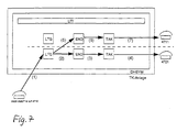
- Fig. 7 is the distribution of a call within a single system shown.
- the subscriber 4710 receives a call: (1). This call is signaled on your own device: (2) to 4). Based on the team data, the LTG component of the Participant 4710 determined that the participant 4711 the Participant 4710 actively monitors and also participant 4711 the call is signaled: (5) to (7).
- the routing processes [(1) to (7)] within the PABX 1 are identical to those of a single system.
- the LTG process of the called party 4710 now determines that this party 4710 also monitored by team partners on other telecommunications systems and the LTG process sends a message to the global UTI process (8).
- the data of the call (phone number of the caller, ...) temporarily stored in the data of the ITT instance.
- the ITT data is then used to determine which real team participants of the corresponding PABX 2 and 3 monitor the subscriber 4710. For each of these team participants it is now determined whether he activates the call pickup in the team Has.
- the UTI process now generates one for all affected RTTs Message to the RTD END process [(10), (14) and (17)].
- This message is sent as the sender of the LTG process Participant 4710 simulated, i.e. for the END process and the following processes [(11), (12), (15), (16), (18) and (19)] the signaling of the team call behaves analogously to one Single asset.
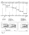
- Fig. 9 this is cross-system routing of a team call shown as a communication diagram.
- the ZVT component sends the S_DT_KLE message to the LTG process of the participant 4710 and signals him that he is called. Signaled with the message LTG_END_TT_RUFT the participant's LTG process 4710 the participant's END process 4711 the team reputation. With the message LTG_UTI_SYN_TT_RUFT becomes the cross-plant routing initiated. The UTI process now sends the message DG_SYM / UTI_SYN_TT_RUFT to the ZVT component. It routes it Datagram then to the PBX 2.
- the ZVT component then sends the message on the PBX 2 DG_SYM / UTI_SYN_TT_RUFT forward to the UTI process.
- the UTI process then determines the affected instances of the team partners and sends the message LTG_END_TT_RUFT to the participant 4712th
- a participant's team data were added parameters extended for cross-system routing; so e.g. the plant number of a TT.
- FIG. 10 shows a schematic illustration for explanation the storage organization in connection with the implementation of a team reputation.
- the team participant indices (tfi) of the different telecommunications systems can assume different values for the same subscriber on the different telecommunications systems, ie the scope of validity of a tti is limited to one system.
- Missing message detection is based on simple Numbering of every message from the team control one PBX is sent to another PBX.
- the team control each individual PBX saves when you receive one Message from a partner system the number of the last received message in a list between (an entry for each partner system). Now the next message from received by the partner system, the cached Number compared with the number of the new message. Is the Number of the new message one more than that of the cached, so no message has been lost and the processing of the call signaling can take place normally. Is the delta between the cached number with the number of the new message not equal to one, so lies an error case. It is now all new messages discarded by the corresponding partner system until all signaling relating to this system is managed back have been.
- the message number When receiving a message from a partner system, the same applies the message number also includes a timestamp in one global list (one entry for each partner system) saved. This list is now cyclical (e.g. once per minute) processed for all partner plants with which active relationships exist, i.e. it becomes the current system time with the saved timestamp of receipt of the last message compared.
- This mechanism ensures that after a finite Time after the connection to a partner system fails all calls are managed back, i.e. a team call rings not forever.
Abstract
Description
Die Erfindung betrifft ein Verfahren zum Betrieb einer Teamkonfiguration
innerhalb einer Anordnung von Telekommunikationseinrichtungen
- z.B. Telekommunikationsanlagen bzw. -
server - nach dem Oberbegriff des Anspruchs 1 sowie eine entsprechende
Anordnung.The invention relates to a method for operating a team configuration
within an array of telecommunications facilities
- e.g. Telecommunication systems or -
server - according to the preamble of
Derartige Verfahren und Anordnungen sind beispielsweise aus der internationalen Offenlegungsschrift WO 98/15134 und der deutschen Offenlegungsschrift DE 197 52 403 A1 bekannt. Sie basieren auf dem Ansatz einer zentralen Steuerung der Teamfunktionalität innerhalb einer Telekommunikationsanlage oder eines Telekommunikationsservers. Dabei laufen entweder die gesamte Steuerung oder zumindest zentrale Teile der Steuerung der Teamfunktionalität innerhalb einer Telekommunikationsanlage ab. Team-Teilnehmer die an eine andere Telekommunikationsanlage angeschlossen sind, werden beispielsweise über sogenannte Verlängerungsverbindungen von der erstgenannten, steuernden Telekommunikationsanlage - in der Literatur häufig auch als zentrale "Masteranlage" bezeichnet - gesteuert.Such methods and arrangements are, for example, from international patent application WO 98/15134 and German patent application DE 197 52 403 A1 known. she are based on the approach of central control of team functionality within a telecommunication system or a telecommunication server. Either run entire controller or at least central parts of the controller the team functionality within a telecommunications system from. Team participants connected to another telecommunications system are connected, for example, via so-called extension connections from the former, controlling telecommunications system - common in the literature also referred to as the central "master system" - controlled.
Eine entsprechende Konfiguration ist schematisch in Fig. 1 dargestellt. Diese Figur ist infolge ihrer Beschriftung selbsterklärend und bedarf daher keiner weiteren Erläuterung.A corresponding configuration is shown schematically in FIG. 1 shown. This figure is due to its lettering self-explanatory and therefore requires no further explanation.
Diese bekannten Lösungen haben im wesentlichen folgende Nachteile:
- Ausfall der Teamfunktionalität in allen abgesetzten Telekommunikationsanlagen bei einem Ausfall der Masteranlage oder bei einem Ausfall der Verbindung zur Masteranlage.
- Beim Ausfall der Masteranlage sind die abgesetzten Team-Teilnehmer nicht mehr erreichbar, können aber selber noch telefonieren.
- Aufgrund der Steuerung der Teamfunktionalität ausgehend von einer zentralen Masteranlage besteht auf der Masteranlage ein erhöhter Performancebedarf.
- Aufgrund der Steuerung jedes einzelnen Team-Teilnehmers ausgehend von einer Masteranlage entsteht ein erhöhtes Signalisierungsaufkommen, da jeder Team-Teilnehmer auf einer abgesetzten Anlage einzeln gesteuert werden muß (z.B. Signalisierung eines Team-Rufes über eine LED einschalten).
- Die beiden obengenannten Punkte bewirken eine schlechte Skalierbarkeit eines derartigen Lösungsansatzes, d.h. große verteilte Teams sind nur schwer realisierbar, da der Signalisierungsaufwand zwischen den abgesetzten Telekommunikationsanlagen und der Masteranlage linear mit der Anzahl der abgesetzten Team-Teilnehmer steigt.
- Failure of the team functionality in all remote telecommunication systems in the event of a failure of the master system or a failure of the connection to the master system.
- If the master system fails, the remote team participants can no longer be reached, but can still make calls themselves.
- Due to the control of the team functionality starting from a central master system, there is an increased performance requirement on the master system.
- Due to the control of each individual team member starting from a master system, there is an increased signaling volume, since each team member must be controlled individually on a remote system (e.g., signaling a team call via an LED).
- The two points mentioned above result in poor scalability of such an approach, ie large, distributed teams are difficult to implement, since the signaling effort between the remote telecommunications systems and the master system increases linearly with the number of remote team participants.
Der Erfindung liegt die Aufgabe zugrunde, ein verbessertes Verfahren der gattungsgemäßen Art sowie eine entsprechende Anordnung anzugeben, die insbesondere eine verbesserte Störsicherheit aufweisen, mit einem geringeren Signalisierungsaufkommen verbunden sind und leichter skalierbar sind.The invention has for its object an improved Processes of the generic type and a corresponding one Specify an arrangement, in particular an improved immunity to interference have a lower signaling volume connected and more easily scalable.
Diese Aufgabe wird hinsichtlich ihres Verfahrensaspektes
durch ein Verfahren mit den Merkmalen des Anspruchs 1 und
hinsichtlich ihres Vorrichtungsaspektes durch eine Anordnung
mit den Merkmalen des Anspruchs 14 gelöst.This task is regarding its procedural aspect
by a method having the features of
Die Erfindung schließt den grundlegenden Gedanken ein, alle Telekommunikationsanlagen der Teamkonfiguration einander gleichwertig auszuführen, d.h. keiner der Telekommunikationsanlagen eine zentrale Rolle bei der Steuerung der Team-Funktionalität zuzuweisen. Sie schließt weiter den Gedanken ein, für jeden Team-Teilnehmer, der zwar konfiguriert ist, jedoch auf einer Telekommunikationsanlage keine physikalische Entsprechung hat, eine imaginäre Instanz (auch "Schatteninstanz" oder "imaginärer Team-Teilnehmer" = ITT genannt) zu verwenden, die für die Steuerung der Teamfunktionalität genutzt wird. Hingegen gibt es auf derjenigen Telekommunikationsanlage, an welcher der entsprechende Teilnehmer physikalisch angeschlossen ist (seiner "Home-Telekommunikationsanlage") eine reale Instanz (auch als "realer Team-Teilnehmer" = RTT bezeichnet). Die imaginären und realen Instanzen der Team-Teilnehmer, d.h. die Team-Daten, existieren neben den eigentlichen Prozeßinstanzen, die für den herkömmlichen Telefoniebetrieb benötigt werden.The invention includes the basic idea, all Team configuration telecommunication systems each other equivalent, i.e. none of the telecommunication systems a central role in controlling team functionality assign. It further includes the thought for each team member that is configured, however no physical equivalent on a telecommunications system has an imaginary instance (also called "shadow instance" or "imaginary team member" = called ITT), which is used to control team functionality becomes. On the other hand, on that telecommunication system, to which the corresponding subscriber is physically connected is (its "home telecommunication system") one real instance (also referred to as "real team member" = RTT). The imaginary and real instances of the team participants, i.e. the team data exist alongside the actual ones Process instances for conventional telephony are needed.
Das Konzept eines "imaginären Team-Teilnehmers" ist in Fig. 2
dargestellt. Ein Teilnehmer mit der Rufnummer 4712 ist an der
Telekommunikationsanlage TK-Anlage 2 (Home) physikalisch angeschlossen
und somit in der Teamsteuerung dieser Telekommunikationsanlage
ein realer Team-Teilnehmer, während er in den
Teamsteuerungen der Telekommunikationsanlagen TK-Anlage 1 und
TK-Anlage 3 als imaginärer Team-Teilnehmer existiert.The concept of an "imaginary team participant" is shown in Fig. 2
shown. A subscriber with the
Infolge des dezentralen Ansatzes der Erfindung ergibt sich eine erhöhte Ausfallsicherheit der Gesamtlösung, d.h. der Ausfall einer Telekommunikationsanlage oder der Verbindung zwischen zwei Telekommunikationsanlagen führt nicht zum Verlust der Teamfunktionalität der restlichen Telekommunikationsanlagen des Netzes, sondern nur zum Ausfall der Teamfunktionalität bezüglich der Team-Teilnehmer im ausgefallen Segment des Netzes.The decentralized approach of the invention results increased reliability of the overall solution, i.e. the Failure of a telecommunication system or the connection between two telecommunication systems does not lead to loss the team functionality of the remaining telecommunications systems of the network, but only to the failure of the team functionality regarding the team participants in the failed segment of the network.
Die Erfindung ermöglicht aufgrund ihrer guten Skalierbarkeit die Realisierung von Teams mit einer großen Anzahl von Teilnehmern in einem Team und einer großen Gesamtanzahl an Team-Teilnehmern insgesamt.The invention enables due to its good scalability the realization of teams with a large number of participants in a team and a large total number of team participants all in all.
Die Erfindung ermöglicht eine Minimierung der Signalisierung zwischen den Telekommunikationsanlagen und benötigt so eine geringere Übertragungsbandbreite zwischen den Telekommunikationsanlagen als andere Lösungen. Die Lösung ermöglicht somit auch eine Kostenersparnis in Fällen, in denen die Telekommunikationsanlagen örtlich getrennt sind und Mietleitungen für die Verbindung der einzelnen Telekommunikationsanlagen untereinander benötigt werden.The invention enables the signaling to be minimized between the telecommunication systems and so needs one lower transmission bandwidth between the telecommunications systems than other solutions. The solution thus enables also a cost saving in cases where the telecommunications equipment are separated and leased lines for the connection of the individual telecommunication systems with each other are needed.
Des weiteren ist die für die Erfindung benötigte Signalisierung zwischen den Telekommunikationsanlagen unabhängig von der genutzten Verbindung zwischen den Telekommunikationsanlagen und kann über verschiedene, auch ungesicherte Verbindungen und Protokolle erfolgen.Furthermore, the signaling required for the invention between the telecommunications systems regardless of the connection used between the telecommunications systems and can be made using various, even unsecured, connections and logs are made.
Die in der Erfindung beschriebene Lösung erkennt selbständig den Verlust von Signalisierungs-bezogenen Nachrichtenelementen oder den Ausfall einer Partneranlage und, verwaltet beim Erkennen eines solchen Fehlerfalls selbständig alle betroffenen Teilnehmersignalisierungen zurück.The solution described in the invention recognizes independently the loss of signaling related message elements or the failure of a partner system and, managed by Detect such an error independently all affected Subscriber signaling back.
Die Erfindung ist ebenfalls dadurch gekennzeichnet, daß auch Inkonsistenzen in den Teamkonfigurationen der verschiedenen Telekommunikationsanlagen innerhalb des Telekommunikationsnetzes selbständig erkannt werden und schwere Fehlerfälle so vermieden werden können.The invention is also characterized in that Inconsistencies in the team configurations of the different Telecommunication systems within the telecommunication network be recognized independently and serious errors like this can be avoided.
Die Erfindung ist dadurch gekennzeichnet, das der Mehraufwand gegenüber einer Teamlösung auf eine einzelne Telekommunikationsanlage gering ist.The invention is characterized in that the additional effort compared to a team solution on a single telecommunication system is low.
Nach obigem sind insbesondere in einer Teamkonfiguration von n Telekommunikationsanlagen jedem Teilnehmer eine einzelne reale Instanz und n-1 imaginäre Instanzen bzw. Schatteninstanzen zugewiesen.According to the above are in a team configuration of n Telecommunication systems each participant one real instance and n-1 imaginary instances or shadow instances assigned.
Einer realen Instanz sind stets auch verschiedene Prozeßinstanzen zugeordnet, da diese für den Telefoniebetrieb benötigt werden. Hingegen verfügt eine imaginäre Instanz nicht über derartige Prozesse, da die imaginären Instanzen selbst kein Kommunikationsendgerät steuern, sondern nur zur Weiterverteilung der Rufe einer realen Instanz dienen. In diesem Sinne ist das Verhältnis einer realen Instanz zu der ihr zugehörigen imaginären Instanzen auch als Master-Slave-Verhältnis zu beschreiben.Different process instances are always a real instance assigned because it is required for telephony become. On the other hand, an imaginary instance does not about such processes because the imaginary instances themselves do not control a communication terminal, but only for further distribution serve the calls of a real instance. In this The meaning is the relationship of a real instance to its associated one imaginary instances also as a master-slave relationship to describe.
Ein wesentlicher Vorteil des mit der Erfindung gewählten Ansatzes besteht darin, daß die realen Instanzen und die imaginären Instanzen bis auf das erwähnte Fehlen der zugehörigen Prozeßinstanzen bei den imaginären Instanzen identisch sind.A major advantage of the approach chosen with the invention is that the real instances and the imaginary Instances except for the aforementioned lack of the associated Process instances are identical in the imaginary instances.
Die Signalisierung zwischen den Telekommunikationsanlagen erfolgt über einzelne Nachrichtenelemente, die nachfolgend auch als "Datagramme" bezeichnet werden.The signaling between the telecommunications systems takes place about individual message elements, the following also referred to as "datagrams".
Nachfolgend werden im Zusammenhang mit der Erläuterung der Erfindung relevante Begriffe und Abkürzungen erklärt:The following are in connection with the explanation of Invention-related terms and abbreviations explained:
eine Gruppe von Teilnehmern:
- die demselben Rufnummernplan angehören,
- die sich auf verschiedenen vernetzten Telekommunikationsanlagen befinden können,
- deren Rufe innerhalb der Gruppe in Abhängigkeit von der Konfiguration signalisiert werden;
- der Teamnummer zugeordnet ist.
- who belong to the same numbering plan,
- which can be located on different networked telecommunication systems,
- whose calls within the group are signaled depending on the configuration;
- is assigned to the team number.
Teilnehmer in einem Team, mit folgenden Merkmalen:
- die kommenden Rufe dieses TT können anderen Teilnehmern im selben Team signalisiert werden;
- diesem TT können die kommenden Rufe anderer Teilnehmer im selben Team signalisiert werden;
- der TT kann die Rufe anderer TT übernehmen;
- die Rufe dieses TT können von anderen TT übernommen werden;
- ein TT kann einem anderen TT einen Ruf zuteilen;
- ein TT kann die Anrufverteilung seiner Rufe ein- oder ausschalten;
- ein TT kann die Anrufübernahme für die ihm signalisierten Rufe seiner Team-Partner ein- oder ausschalten.
- the incoming calls of this TT can be signaled to other participants in the same team;
- This call can signal the incoming calls of other participants in the same team;
- the TT can take over the calls of other TT;
- the calls of this TT can be taken over by other TT;
- one TT can assign a call to another TT;
- a TT can switch the call distribution of its calls on or off;
- a TT can switch call pickup on or off for the calls signaled to him by his team partners.
Dieser Teilnehmer hat auf der Telekommunikationsanlage, die diesen Teilnehmer betrachtet, eine logische Adresse, hinter der sich eine Rufnummer befindet, und folgende Merkmale aufweist:
- ein RTT ist sowohl auf Einzelanlagen als auch bei vernetzten Telekommunikationsanlagen möglich;
- bei einem RTT im Anlagenverbund wird auch vom Home des TT gesprochen;
- ein RTT kann teilnehmerindividuelle Daten sichern und so z.B. speichern, an welcher Tastenposition ein anderer Team-Partner überwacht wird;
- ein RTT verfügt typischerweise über eine physikalische Entsprechung (d.h. ein angeschlossenes Kommunikationsendgerät); ein RTT kann aber auch ein "virtueller Team-Teilnehmer sein.
- an RTT is possible both on individual systems and in networked telecommunications systems;
- in the case of an RTT in the system network, the home of the TT is also spoken of;
- an RTT can save subscriber-specific data and thus save, for example, the key position at which another team partner is monitored;
- an RTT typically has a physical equivalent (ie a connected communication terminal); an RTT can also be a "virtual team participant.
Dieser Teilnehmer befindet sich nicht auf der Anlage, die diesen Teilnehmer betrachtet, d.h. er hat auf dieser Anlage keine physikalische oder virtuelle Entsprechung und natürlich auch keine logische Adresse und folgende weitere Merkmale:
- die Rufnummer dieses Teilnehmers ist im gleichen Wählbaum wie die seiner Team-Partner und verweist auf die Anlassung zu einer anderen Anlage;
- zu einem ITT gehört immer ein RTT;
- bei n-vernetzten Telekommunikationsanlagen gehören zu einem RTT (n-1) ITT's;
- ein ITT hat keine Instanzdaten für ein Kommunikationsendgerät, sondern nur Team-Daten;
- ein ITT kann keine teilnehmerindividuellen Daten sichern;
- die Daten eines ITT's werden u.a. aus den Team-Daten der RTT's der Anlage rekonstruiert;
- ein ITT verteilt die Rufe des zugehörigen RTT einer Partneranlage.
- the number of this subscriber is in the same dialing tree as that of his team partners and refers to the reason for another system;
- an ITT always has an RTT;
- in the case of n-networked telecommunication systems, an RTT (n-1) includes ITT's;
- an ITT has no instance data for a communication terminal, only team data;
- an ITT cannot save subscriber-specific data;
- the data of an ITT are reconstructed from the team data of the RTTs of the plant;
- an ITT distributes the calls of the associated RTT of a partner system.
Ein virtueller Team-Teilnehmer ist ein Team-Teilnehmer ohne physikalische Entsprechung, d.h. ein Teilnehmer mit eigener logischen Adresse, eigenen Instanzdaten und eigener Rufnummer, der Team-Rufe verteilen kann, aber über keine zugehörige Physik verfügt und folgende weitere Merkmale hat:
- der VTT kann selbst keinen Ruf annehmen oder gehend eine Leitung belegen;
- der VTT wird z.B. für die Anrufverteilung im Team benutzt;
- ein VTT ist ein Hilfskonstrukt in einer Teamkonfiguration, das, unabhängig von der Vernetzungs-Problematik, dazu genutzt wird, die Anzahl der von extern erreichbaren Rufnummern im Team zu erhöhen, ohne die Anzahl der tatsächlichen Teilnehmer zu erhöhen (So kann ein Teilnehmer z.B. unter 3 verschiedenen Rufnummern erreichbar sein).
- the VTT itself cannot accept a call or seize a line;
- the VTT is used, for example, for call distribution in a team;
- A VTT is an auxiliary construct in a team configuration that, regardless of the networking problem, is used to increase the number of externally accessible phone numbers in the team without increasing the number of actual subscribers (for example, a subscriber under 3 different numbers can be reached).
Alle TT innerhalb eines Teams, außer dem TT selber.All TT within a team, except the TT itself.
Taste eines TT, der einen TTP überwacht;
- TK's sind entweder vom Konfigurator fest vorgegeben oder können entsprechend der Vorgaben des Konfigurators frei programmiert werden;
- TK's werden durch eine virtuelle Tastenposition der Rufnummer des Team-Partners, die Signalisierungsart und den zugehörigen Rufrythmus beschrieben.
- TCs are either predefined by the configurator or can be freely programmed according to the configurator's specifications;
- TCs are described by a virtual key position of the team partner's number, the type of signaling and the associated call rhythm.
Option eines TT einen TP auf eine frei programmierbare Funktionstaste speichern zu können. Option of a TT a TP on a freely programmable function key to be able to save.
Vom Home eines Team-Teilnehmers spricht man bei vernetzten Telekommunikationsanlagen, wenn es sich um den RTT (s.o.) handelt.One speaks of a team member's home in networked Telecommunications systems, if it is the RTT (see above) is.
Eineindeutige Abbildung einer physikalischen Tastenposition (Tastennummer + Angabe Endgerät bzw. Rufnummerngeber) auf einen zusammenhängenden Zahlenbereich.Clear illustration of a physical key position (Key number + specification of terminal or number transmitter) on one contiguous range of numbers.
Die logische Adresse ist ein eindeutiger Index zur Adressierung
eines Teilnehmers innerhalb einer Telekommunikaitonsanlage
(eine Rufnummer stellt nur bei einem einheitlichen Rufnummernplan
einen eindeutigen Index dar, prinzipiell werden
auch geschlossene Teilnehmergruppen verwandt und es ist möglich,
innerhalb von verschiedenen geschlossenen Teilnehmergruppen
eine Rufnummer mehrfach zu verwenden).
Eine logische Adresse ist nur innerhalb einer Telekommunikationsanlage
ein eineindeutiger Index und gilt nicht anlagen-übergreifend.The logical address is a unique index for addressing a subscriber within a telecommunications system (a phone number is only a unique index with a uniform phone number plan, in principle closed subscriber groups are also used and it is possible to use a phone number multiple times within different closed subscriber groups) ,
A logical address is a unique index only within a telecommunication system and does not apply to all systems.
Für jeden Teilnehmer werden für den Betrieb verschiedene Prozesse
(z.B. LTG, END, TAK) und die dazugehörigen Datenbereiche
benötigt.
Diese werden auch als Instanz bzw. Inkarnation dieses Teilnehmers
bezeichnet.Various processes (e.g. LTG, END, TAK) and the associated data areas are required for each participant for operation.
These are also referred to as the instance or incarnation of this participant.
Jeder Teilnehmer verfügt über eigene Instanzdaten, die seine aktuellen Stati, seine Konfiguration und seine teilnehmerindividuellen Daten beinhalten. Diese Daten werden teilweise auch gesichert und stehen dann auch nach einem Ausfall der Telekommunikationsanlage wieder zur Verfügung. Each participant has their own instance data, their current status, its configuration and its subscriber-specific Include data. This data is partial also secured and then stand even after a failure of the Telecommunications system available again.
Das sind diejenigen Daten, die für die Teamfunktionalität benötigt werden, mit folgenden Merkmalen:
- die Team-Daten sind an die Rufnummer und die Teamnummer eines Team-Teilnehmers gebunden;
- über die Instanzdaten eines RTT ist mit Hilfe des Team-Teilnehmer Index (M) ein Zugriff auf die eigenen Team-Daten und die Team-Daten der Team Partner möglich;
- ein zentraler Prozeß (UTI) kann auf die Team-Daten aller Team-Teilnehmer zugreifen;
- ITT's verfügen nur über Team-Daten (es gibt keine Instanz und keine Instanzdaten (END-,LTG und TAK-Prozeß)für einen ITT).
- the team data are linked to the phone number and the team number of a team member;
- With the help of the team participant index (M), the own team data and the team data of the team partners can be accessed via the instance data of an RTT;
- a central process (UTI) can access the team data of all team participants;
- ITTs only have team data (there is no instance and no instance data (END, LTG and TAK process) for an ITT).
Innerhalb der Teamsteuerung einer Telekommunikationsanlage eindeutiger Index, der einen Team-Teilnehmer identifiziert.Within the team control of a telecommunication system unique index that identifies a team member.
Derjenige Teil einer Telekommunikationsanlage, der u.a. für die Konfiguration der Telekommunikationsanlage zuständig ist.The part of a telecommunications system that, among other things, For the configuration of the telecommunications system is responsible.
Derjenige Teil in einer Telekommunikationsanlage, der für den Aufbau und die Abwicklung von "klassischen" Vermittlungsfunktionen zuständig ist.The part in a telecommunications system that for the Development and handling of "classic" mediation functions responsible is.
Derjenige Teil der Telekommunikationsanlage, der für die
Steuerung von Systemendgeräten zuständig ist.
In diesem DHSYM ist die der Erfindung zugrundeliegende Teamsteuerung
realisiert.The part of the telecommunications system that is responsible for the control of system terminals.
The team control on which the invention is based is implemented in this DHSYM.
Verschiedene Prozesse für die Steuerung eines Endgerätes innerhalb des DHSYM, die für jeden Teilnehmer einmal vorhanden sind. Different processes for the control of a device within of the DHSYM, which is available once for each participant are.
Zentraler Prozeß innerhalb des DHSYM, der für alle Endgeräte nur einmal existiert.Central process within the DHSYM, for all devices only exists once.
Vorteile und Zweckmäßigkeiten der Erfindung ergeben sich - neben den oben erwähnten grundsätzlichen Aspekten - aus den Unteransprüchen sowie der nachfolgenden Beschreibung bevorzugter Aspekte und Ausführungsformen der Erfindung anhand der Figuren 3 bis 10.Advantages and advantages of the invention result - in addition to the basic aspects mentioned above - from the Subclaims and the following description are more preferred Aspects and embodiments of the invention based on the Figures 3 to 10.
- Fig. 3:Fig. 3:
- eine schematische Darstellung einer verteilten Teamkonfiguration aus fünf Teilnehmern,a schematic representation of a distributed Team configuration of five participants,
- Fig. 4:Fig. 4:
- eine Darstellung zur Verteilung eines kommenden Rufes innerhalb des verteilten Teams nach Fig. 3,a representation of the distribution of an incoming call within the distributed team according to FIG. 3,
- Fig. 5:Fig. 5:
-
eine beispielhafte Darstellung zur Erläuterung der
Fehlererkennung und -behandlung bei einer Teamkonfiguration
nach Fig. 3,an exemplary representation to explain the
Error detection and handling in a
team configuration 3, - Fig. 6:Fig. 6:
- eine schematische Darstellung zum Aufbau von Telekommunikationsanlagen, aus denen eine Anordnung gemäß einem Ausführungsbeispiel der Erfindung gebildet ist,a schematic representation of the construction of telecommunications systems, from which an arrangement according formed an embodiment of the invention is
- Fig. 7:Fig. 7:
- eine schematische Darstellung zur Verteilung eines Team-Rufes in einer Einzelanlage gemäß einer Ausführungsform der Erfindung,a schematic representation of the distribution of a Team reputation in a single system according to one embodiment the invention,
- Fig. 8:Fig. 8:
- eine schematische Darstellung eines netzübergreifenden Routing eines Rufes gemäß einer Ausführungsform der Erfindung,a schematic representation of a cross-network Routing a call according to one embodiment the invention,
- Fig. 9:Fig. 9:
- eine Darstellung eines anlagenübergreifenden Kommunikationsdiagramms bei einer Ausführungsform der Erfindung unda representation of a cross-system communication diagram in one embodiment of the Invention and
- Fig. 10:Fig. 10:
- eine schematische Darstellung zur Erläuterung der Speicherorganisation im Zusammenhang mit der Realisierung eines Team-Rufes bei einer Ausführungsform der Erfindung.a schematic representation to explain the Storage organization in connection with the realization a team call in one embodiment the invention.
In Fig. 3 ist eine verteilte Teamkonfiguration aus 5 Teilnehmern
dargestellt. An der TK-Anlage 1 und der TK-Anlage 3 sind
jeweils zwei Team-Teilnehmer physikalisch angeschlossen. An
der TK-Anlage 2 ist ein Team-Teilnehmer physikalisch angeschlossen.
Dementsprechend verfügen die einzelnen TK-Anlagen
über unterschiedliche RTT- und ITT-Instanzen (siehe Tabelle
1).
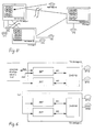
In Fig. 4 ist ein Fall schematisch dargestellt, bei dem ein
kommender Ruf innerhalb des Teams zwischen den TK-Anlagen 1,
2 und 3 verteilt wird.4 schematically shows a case in which a
incoming call within the team between the
In einem ersten Schritt 1) wird der kommende Ruf der RTT-Instanz
des Teilnehmers 4710 auf der TK-Anlage 1 zugestellt.In a first step 1) the incoming call of the RTT instance
of
In einem zweiten Schritt 2) wird der kommende Ruf dem Teilnehmer
4710 zugestellt, d.h. es klingelt am Kommunikationsendgerät
mit der Rufnummer 4710.In a second step 2) the incoming call is the
In einem dritten Schritt 3) wird der Ruf an den Team-Partner
4711 innerhalb der TK-Anlage 1 verteilt.In a third step 3) the call to the
In einem vierten Schritt 4) stellt die RTT-Instanz des Teilnehmers
4710 fest, daß dieser Teilnehmer eine Anrufverteilung
aktiviert hat und auch von Team-Partnern auf der TK-Anlage 3
überwacht wird. Die RTT-Instanz des Teilnehmers 4710 sendet
daraufhin eine Nachricht mit den Parametern des Rufes an die
TK-Anlage 3, unabhängig davon, wieviele Teilnehmer auf der
TK-Anlage 3 den Teilnehmer 4710 überwachen und unabhängig davon,
ob diese Teilnehmer die Anrufübernahme für Team-Rufe aktiviert
haben oder nicht.In a fourth step 4), the RTT instance of the
Hat der Teilnehmer 4710 die Anrufverteilung nicht aktiviert,
so werden die Parameter des Rufes zwar zwischengespeichert,
die TK-Anlagen 2 und 3 werden aber nicht über diesen Ruf benachrichtigt.
Erst wenn der Teilnehmer 4710 die Anrufverteilung
aktiviert und in Fällen, in denen der Ruf immer noch ansteht,
erfolgt eine Benachrichtigung der TK-Anlagen 2 und 3.
In der ITT-Instanz des Teilnehmers 4710 werden die Parameter
des kommenden Rufes gespeichert und gegebenenfalls an die
Team-Teilnehmer verteilt [siehe folgenden Schritte 5) und
6)].If
Gibt es auf der TK-Anlage 2 keine ITT-Instanz für den Teilnehmer
4710, was z.B. bei einer inkonsistenten Datenbasis der
vernetzten TK-Anlagen der Fall wäre, so kann dieser Fehlerfall
jetzt erkannt werden und eine entsprechende Fehlerreaktion
ausgelöst werden.There is no ITT instance for the subscriber on
In einem fünften Schritt 5) stellt die RTT-Instanz des Teilnehmers
4710 fest, daß der Teilnehmer 4710 auch von Team-Partnern
auf der TK-Anlage 2 überwacht wird, und sendet auch
an die TK-Anlage 2 eine Nachricht [analog zu Schritt 3)].In a fifth step 5), the RTT instance of the
Der ITT-Instanz des Teilnehmers 4710 wurde in kommender Ruf
signalisiert. In einem sechsten Schritt 6) wird dieser Ruf
nun an die entsprechenden Team-Partner verteilt. Anhand der
Daten der ITT-Instanz des Teilnehmers 4710 auf der TK-Anlage
3 wird festgestellt, daß dieser von dem Teilnehmer 4723 überwacht
wird, und über die RTT-Instanz des Teilnehmers 4723
wird ermittelt, daß der Teilnehmer 4723 die Anrufübernahme
aktiviert hat. Nun wird dem Team-Teilnehmer 4723 der kommende
Ruf derart signalisiert, als wäre es der Team-Ruf für einen
Team-Partner der eigenen TK-Anlage 3. The ITT instance of
In einem siebten Schritt wird analog zu Schritt 6) dem Teilnehmer 4713 der Team-Ruf signalisiert.In a seventh step, the participant becomes analogous to step 6) 4713 the team call signals.
In einem achten Schritt wird analog zu Schritt 6) dem Teilnehmer
4712 auf der TK-Anlage 2 der Team-Ruf signalisiert.In an eighth step, the participant becomes analogous to step 6)
4712 on the
Die vernetzte Signalisierung anderer Vermittlungsstati, wie beispielsweise
- Team-Teilnehmer ist belegt,
- Team-Teilnehmer ist frei,
- Ende des Rufes für den Team-Teilnehmer
- Team participant is busy
- Team participant is free
- End of the call for the team member
Wird einem Team-Teilnehmer, z.B. der Teilnehmer 4713, ein Ruf
für einen Team-Partner, z.B. 4710, auf einer anderen TK-Anlage
signalisiert, so kann der Team-Teilnehmer diesen Ruf für
seinen Team-Partner annehmen. Dies erfolgt über eine gezielte
Rufabfrage, d.h. der Teilnehmer 4713 signalisiert der TK-Anlage
1, daß er den Ruf für den Teilnehmer 4710 annehmen will
und die TK-Anlage 1 übergibt diesen Ruf an Teilnehmer 4713
auf der TK-Anlage 3.If a team member, e.g. the
Die Erfindung nutzt verschiedene Mechanismen der Fehlererkennung, um ein stabiles Arbeiten eines vernetzten Team zu sichern, so z.B.:
- das Erkennen des Ausfalls einer Partner-TK-Anlage bzw. des Ausfalls der Routingwege zu dieser TK-Anlage,
- das Erkennen dessen, daß eine Partner-TK-Anlage neu hochgelaufen ist,
- das Erkennen von Verlusten einer oder mehrerer Nachrichten in der Kommunikation mit einer Partneranlage,
- das Erkennen von inkonsistenten Teamkonfigurationen.
- the detection of the failure of a partner PBX or the failure of the routing routes to this PBX,
- recognizing that a partner PBX has started up,
- the detection of losses of one or more messages in the communication with a partner system,
- the detection of inconsistent team configurations.
Erkennt die Teamsteuerung eine gestörte Kommunikation zu einer Partneranlage, so werden alle Signalisierungen von Vermittlungsstati, die diese TK-Anlage betreffen, zurückverwaltet, d.h. ein anstehender Team-Ruf wird automatisch durch ein "Ruf aus" beendet, unabhängig davon, ob der Partner noch gerufen wird oder nicht. In dem Zeitraum, der benötigt wird, die Querbeziehungen zu der ausgefallenen Partneranlage zurückzuverwalten, werden keine neuen Anreize von der ausgefallen Partneranlage akzeptiert. Nachdem alle Rufstati zurückverwaltet wurden, steht die Teamfunktionalität bezüglich der ausgefallenen TK-Anlage nicht mehr zur Verfügung.If the team management detects a faulty communication with one Partner system, so all signaling of switching status, managed back to those PBXs, i.e. an upcoming team call is automatically indicated by a "Call off" ended regardless of whether the partner is still called will or not. In the period that is needed manage the cross-relationships to the failed partner system, there will be no new incentives from the Partner facility accepted. After all call states are managed back the team functionality regarding the failed PBX is no longer available.
Erhält die TK-Anlage nun wieder einen Anreiz von der vorher ausgefallenen Partneranlage, beginnt die Signalisierung von Rufstati erneut, d.h. die anlagenübergreifende Funktionalität steht nun wieder zur Verfügung. Aus Performancegründen erfolgt beim "Erstkontakt" oder beim "Wiedertreffen" der vernetzten TK-Anlagen kein Refresh aller Vermittlungsstati der Team-Teilnehmer.The PBX now receives an incentive from the previous one failed partner system, the signaling of Call status again, i.e. the cross-system functionality is now available again. For performance reasons at the "first contact" or at the "reunion" of the networked PBXs no refresh of all switching states Team participants.
In Fig. 5 wird angenommen, daß die Verbindungen der TK-Anlage
1 zu den TK-Anlagen 2 und 3 durchgetrennt sind. Die Amtsverbindung
der TK-Anlage 1 ist aber erhalten geblieben und der
Teilnehmer 4710 wird weiterhin gerufen. Dem Team-Partner 4711
auf der TK-Anlage 1 wird der Ruf auch weiterhin signalisiert
und der Ruf kann auch angenommen werden.In Fig. 5 it is assumed that the connections of the
Die Teamsteuerungen der TK-Anlagen 2 und 3 erkennen - etwa
nach einem bestimmten Zeitraum, oder beim Versuch den Ruf für
den Team-Partner 4710 anzunehmen - daß die Verbindung zu der
TK-Anlage 1 unterbrochen ist. Die Signalisierung des Rufes
für den Team-Teilnehmer 4710 wird nun selbständig durch die
Teamsteuerungen der TK-Anlagen 2 und 3 rückverwaltet und
nicht wie im "normalen" Betrieb durch die TK-Anlage 1. Die
Teamfunktionalität der TK-Anlagen 2 und 3 ist nun um die
Teilnehmer Anlage 1 eingeschränkt, so wie auch auf der Anlage
1 nur noch lokale Teamfunktionalität zur Verfügung steht.Recognize the team controls of
Die netzübergreifende Funktionalität der TK-Anlagen 2 und 3
ist aber noch voll vorhanden, d.h. erhält der Teilnehmer 4723
der TK-Anlage 3 nun einen Ruf, so wird dieser Ruf auch bei
dem Team-Teilnehmer 4712 auf der TK-Anlage 2 signalisiert.
Hierin zeigt sich die größere Robustheit der beschriebenen
Lösung gegenüber einer nicht vollständig dezentralen Lösung,
wie sie z.B. in der internationalen Offenlegungsschrift WO
98/15135 beschrieben ist.The cross-network functionality of
Die Konfiguration der netzübergreifenden Teams erfolgt durch ein Programm, das auf einer der TK-Anlagen läuft oder auf einem externen Rechner gestartet wird. Dieses Programm läuft unabhängig von der eigentlichen Teamsteuerung und wird für den eigentlichen Betrieb des Teams nicht benötigt, sondern nur für die netzübergreifende Konfiguration.The cross-network teams are configured by a program that runs on one of the PBXs or on one external computer is started. This program is running independent of the actual team control and is used for does not need the actual operation of the team, but rather only for cross-network configuration.
Die Teamkonfiguration ist für die Konsistenz der Daten der verteilten Teams zuständig und ermöglicht es, neue Team-Teilnehmer in ein Team aufzunehmen, Teilnehmer aus einem Team zu löschen oder die Vorgaben, welcher Team-Teilnehmer welchen Team-Partner monitoren darf, zu ändern. Hierzu fordert dieses Programm die aktuelle Teamkonfiguration von den einzelnen TK-Anlagen an und arbeitet dann mit den Daten der "realen Team-Teilnehmer" (RTT).The team configuration is for the consistency of the data distributed teams and enables new team participants to include in a team, participants from a team delete or the specifications of which team participants which Team partners may monitor changes. This calls for this Program the current team configuration of the individual PBXs and then works with the data of the "real team participants" (RTT).
Die anlagenweit angebotene Teamfunktionalität entspricht der
in der deutschen Offenlegungsschrift DE 197 52 403 A1 beschriebenen
Teamfunktionalität einer Einzelanlage. Es werden
folgende Teamleistungsmerkmale realisiert:
- akustisch (Normalruf oder Kurzruf)
- im Display des entsprechenden Endgerätes
- an der LED der entsprechenden Team-Taste am Endgerät (blinken)
- über die Team-Taste am Endgerät
- über einen entsprechenden Menüpunkt im Display, auch wenn es die korrespondierende Team-Taste physikalisch gar nicht gibt, z.B. an einem DECT-Mobiltelefon
- über eine separate Funktionstaste
- über einen Menüpunkt
- über eine separate Funktionstaste
- über einen Menüpunkt
- acoustic (normal call or short call)
- in the display of the corresponding end device
- on the LED of the corresponding team key on the end device (flashing)
- via the team button on the end device
- via a corresponding menu item in the display, even if the corresponding team key does not physically exist, for example on a DECT mobile phone
- via a separate function key
- via a menu item
- via a separate function key
- via a menu item
Der Aufbau einer TK-Anlage, wie sie in der Erfindung genutzt wird, und die verschiedenen zugehörigen Module, Tasks bzw. Prozesse sind früher bereits ausführlich beschrieben worden und wird im folgenden nur kurz skizziert. The construction of a telecommunications system, as used in the invention and the various associated modules, tasks or Processes have previously been described in detail and is only briefly outlined below.
In Fig. 6 sind zwei vernetzte TK-Anlagen vereinfacht dargestellt. Die Teamsteuerung ist hierbei dem Komplex DHSYM zugeordnet. Die Endgeräte mit Teamfunktionalität werden durch den DHSYM gesteuert. Der DHSYM kommuniziert über die internen Schnittstellen #l1 und #l2 mit den Komponente ZBT und ZVT.In Fig. 6 two networked PBXs are shown in simplified form. Team control is assigned to the DHSYM complex. The end devices with team functionality are provided by the DHSYM controlled. The DHSYM communicates via the internal Interfaces # l1 and # l2 with the components ZBT and ZVT.
Über die Schnittstelle #l1 erfolgt die Kommunikation, die für die Konfiguration der Team-Daten notwendig ist. Über die Schnittstelle #l2 erfolgt die Kommunikation, die für die anlagenübergreifende Rufsignalisierung innerhalb vernetzter Teams notwendig ist.The communication that takes place via the interface # l1 the configuration of the team data is necessary. About the Interface # l2 is the communication for cross-plant Call signaling within networked Teams is necessary.
Der DHSYM adressiert über die ZVT-Komponente der eigenen TK-Anlage die externe Schnittstelle #e1 und darüber die ZVT-Komponente der Partneranlage, die diese Signalisierung an den DHSYM der Partneranlage weiterreicht. Die externen Schnittstellen #e2 und #e3 dienen der ZBT-Komponente u. a. zur Konfiguration von anlagenübergreifenden Teams.The DHSYM addresses via the ZVT component of your own PABX the external interface # e1 and above it the ZVT component the partner system that sends this signaling to the DHSYM passes the partner system. The external interfaces # e2 and # e3 serve the ZBT component u. a. for configuration of cross-plant teams.
In Fig. 7 ist die Verteilung eines Rufes innerhalb einer Einzelanlage
dargestellt. Der Teilnehmer 4710 erhält einen Ruf:
(1). Dieser Ruf wird am eigenen Endgerät signalisiert: (2)
bis (4). Anhand der Team-Daten wird in der LTG-Komponente des
Teilnehmers 4710 festgestellt, das der Teilnehmer 4711 den
Teilnehmer 4710 aktiv monitort und auch beim Teilnehmer 4711
wird der Ruf signalisiert: (5) bis (7).In Fig. 7 is the distribution of a call within a single system
shown. The
Die hier dargestellte Steuerung eines Endgerätes durch die drei Prozesse LTG, END und TAK ist nur beispielhaft für die konkrete Umsetzung der Erfindung. Prinzipiell kann die der Erfindung zugrunde liegende Teamsteuerung auch mit einer anders strukturierten Endgerätesteuerung zusammenarbeiten (z.B. nur einen Prozeß je Endgerät). The control of a terminal shown here by the three processes LTG, END and TAK is only exemplary for the concrete implementation of the invention. In principle, the Team control on which the invention is based also with another work together with structured terminal control (e.g. only one process per terminal).
In Fig. 8 ist das netzübergreifende Routing eines Team-Rufes
dargestellt. Wie bereits in Fig. 7 wird der Teilnehmer 4710
gerufen.The cross-network routing of a team call is shown in FIG. As already in FIG. 7,
Die Abläufe des Routings [(1) bis (7)] innerhalb der TK-Anlage
1 sind mit denen einer Einzelanlage identisch. Durch
einen Zugriff auf die Team-Daten stellt der LTG-Prozeß des
gerufenen Teilnehmers 4710 nun fest, daß dieser Teilnehmer
4710 auch von Team-Partnern auf anderen TK-Anlagen überwacht
wird, und der LTG-Prozeß sendet eine Nachricht an den globalen
UTI-Prozeß (8).The routing processes [(1) to (7)] within the
Dieser UTI-Prozeß hat den Zugriff auf die Team-Daten aller Teilnehmer (ITT & RTT). Der UTI-Prozeß ermittelt nun anhand der Team-Daten auf welchen TK-Anlagen des Netzes der Teilnehmer 4710 noch überwacht wird und erstellt so eine Liste mit den betroffenen TK-Anlagen zusammen. An jede betroffene TK-Anlage, d.h. an jede TK-Anlage im Netz, an der mindestens ein Team-Teilnehmer den Teilnehmer 4710 überwacht, wird nun eine Nachricht [(9) und (13)] gesendet, die folgende Informationen enthält:
der Teilnehmer 4710 wird gerufender Teilnehmer 4710 ist im Team Nr.2- die Parameter des Rufes, z.B.:
- wenn bekannt, die Rufnummer und den Namen des Rufers
- den Rufrythmus
- die Teilnehmerart des Rufers etc.
-
subscriber 4710 is called -
participant 4710 is in team no.2 - the parameters of the call, for example:
- if known, the call number and the name of the caller
- the rhythm of calls
- the type of subscriber of the caller etc.
In den TK-Anlagen 2 und 3 wird nun nach Erhalt der Nachrichten
(9) und (13) untersucht, ob es in den Team-Daten der Anlagen
2 und 3 einen "imaginären Team-Teilnehmer" mit der Rufnummer
4710 gibt, der im Team Nr. 2 ist.In the
Ist das nicht der Fall, so handelt es sich um eine inkonsistente Teamkonfiguration und nun kann eine Fehlerbehandlung einsetzen, z.B. kann eine Fehlermeldung abgesetzt werden. If this is not the case, it is an inconsistent one Team configuration and now can error handling use, e.g. an error message can be issued.
Wurde aber eine ITT-Instanz zu der Rufnummer 4710 im Team Nr.
2 gefunden, so werden zuerst die Daten des Rufes (Rufnummer
des Rufers, ...) in den Daten der ITT-Instanz zwischengespeichert.
Danach wird anhand der Daten des ITT ermittelt, welche
realen Team-Teilnehmer der entsprechenden TK-Anlage 2 und 3
den Teilnehmer 4710 monitoren. Für jeden dieser Team-Teilnehmer
wird nun ermittelt, ob er die Anrufübernahme im Team aktiviert
hat.However, if an ITT instance was assigned to the
Für alle betroffenen RTT generiert nun der UTI-Prozeß eine
Nachricht an den END-Prozeß des RTT [(10), (14) und (17)]. In
dieser Nachricht wird als Absender des LTG-Prozesses der
Teilnehmer 4710 vorgetäuscht, d.h. für den END-Prozeß und die
folgenden Abläufe [(11), (12), (15), (16), (18) und (19)]
verhält sich die Signalisierung des Team-Rufes analog zu einer
Einzelanlage.The UTI process now generates one for all affected RTTs
Message to the RTD END process [(10), (14) and (17)]. In
This message is sent as the sender of the
Hatte nun aber ein RTT, z.B. 4723 auf der TK-Anlage 3, die
Anrufübernahme nicht aktiviert, der Ruf steht noch an und der
Teilnehmer aktiviert nun doch die Anrufübernahme, so kann der
Ruf anhand der in den ITT-Daten zwischengespeicherten Rufdaten
auch verzögert zugestellt werden. Hat der Teilnehmer 4710
aber die Anrufverteilung ausgeschaltet und wird er gerufen,
so werden die Daten des Rufes in den Team-Daten des Teilnehmers
(RTT) zwischengespeichert, aber nicht verteilt. Schaltet
der Teilnehmer 4710 nun die Anrufverteilung ein und der Ruf
steht immer noch an, so wird der Ruf anhand der in der Team-Daten
zwischengespeicherten Daten verteilt.But now had an RTT, e.g. 4723 on the
In Fig. 9 ist das anlagenübergreifende Routen eines Team-Rufes als Kommunikationsdiagramm dargestellt.In Fig. 9 this is cross-system routing of a team call shown as a communication diagram.
Die Komponente ZVT sendet die Nachricht S_DT_KLE an den LTG-Prozeß
des Teilnehmers 4710 und signalisiert ihm so, daß er
gerufen wird. Mit der Nachricht LTG_END_TT_RUFT signalisiert
der LTG-Prozeß des Teilnehmer 4710 dem END-Prozeß des Teilnehmers
4711 den Team-Ruf. Mit der Nachricht
LTG_UTI_SYN_TT_RUFT wird das anlagenübergreifende Routing
eingeleitet. Der UTI-Prozeß sendet nun die Nachricht
DG_SYM/UTI_SYN_TT_RUFT an die ZVT-Komponente. Die routet das
Datagramm dann zu der TK-Anlage 2.The ZVT component sends the S_DT_KLE message to the LTG process
of the
Auf der TK-Anlage 2 sendet dann die ZVT-Komponente die Nachricht
DG_SYM/UTI_SYN_TT_RUFT weiter an den UTI-Prozeß. Der
UTI-Prozeß ermittelt dann die betroffenen Instanzen der Team-Partner
und sendet die Nachricht LTG_END_TT_RUFT an den Teilnehmer
4712.The ZVT component then sends the message on the
Die Strukturierung der Team-Daten wurde bereits früher eingehend beschrieben.The structuring of the team data has already been discussed in detail earlier described.
Die Team-Daten eines Teilnehmers wurden um zusätzliche Parameter für das anlagenübergreifende Routing erweitert; so z.B. der Anlagennummer eines TT.A participant's team data were added parameters extended for cross-system routing; so e.g. the plant number of a TT.
Fig. 10 zeigt eine schematische Darstellung zur Erläuterung der Speicherorganisation im Zusammenhang mit der Realisierung eines Team-Rufes.10 shows a schematic illustration for explanation the storage organization in connection with the implementation of a team reputation.
Der Zugriff auf die Daten wird am Beispiel der anlagenübergreifenden
Signalisierung eines Team-Rufes dargestellt.
Ein Team-Teilnehmer (Ruf-Nr. 4710) auf Anlage 1 wird vom Amt
(Ruf-Nr. 05251820718) gerufen. Ein weiterer Team-Teilnehmer
(Ruf-Nr. 4712) im selben Team, aber auf einer anderen Anlage
(Anlage 2), überwacht den Gerufenen auf einer Team-Taste
(Team Key). An der LED dieser Team-Taste, über einen Kurzruf
und im Display wird der kommende Ruf des Team-Partners beim
Teilnehmer (4712) signalisiert.
A team member (call no. 4710) on
Die Team-Teilnehmer Indizes (tfi) der verschieden TK-Anlagen können für ein und denselben Teilnehmer auf den unterschiedlichen TK-Anlagen verschiedene Werte annehmen, d.h. der Gültigkeitsbereich eines tti ist auf eine Anlage beschränkt.The team participant indices (tfi) of the different telecommunications systems can assume different values for the same subscriber on the different telecommunications systems, ie the scope of validity of a tti is limited to one system.
Das Erkennen inkonsistenter Team Konfigurationen wurde bereits weiter oben beschrieben.Detecting inconsistent team configurations has already been done described above.
Das Erkennen fehlender Nachrichten basiert auf der einfachen Numerierung jeder Nachricht, die von der Teamsteuerung einer TK-Anlage zu einer anderen TK-Anlage gesendet wird. Die Teamsteuerung jeder einzelnen TK-Anlage speichert beim Erhalt einer Nachricht von einer Partneranlage die Nummer der zuletzt empfangenen Nachricht in einer Liste zwischen (ein Eintrag für jede Partneranlage). Wird nun die nächste Nachricht von der Partneranlage empfangen, so wird die zwischengespeicherte Nummer mit der Nummer der neuen Nachricht verglichen. Ist die Nummer der neuen Nachricht um eins größer als die der zwischengespeicherten, so ist keine Nachricht verloren gegangen und die Abarbeitung der Rufsignalisierung kann normal erfolgen. Ist das Delta zwischen der zwischengespeicherten Nummer mit der Nummer der neuen Nachricht ungleich eins, so liegt ein Fehlerfall vor. Es werden nun solange alle neuen Nachrichten von der entsprechenden Partneranlage verworfen, bis alle diese Anlage betreffenden Signalisierungen zurückverwaltet worden sind.Missing message detection is based on simple Numbering of every message from the team control one PBX is sent to another PBX. The team control each individual PBX saves when you receive one Message from a partner system the number of the last received message in a list between (an entry for each partner system). Now the next message from received by the partner system, the cached Number compared with the number of the new message. Is the Number of the new message one more than that of the cached, so no message has been lost and the processing of the call signaling can take place normally. Is the delta between the cached number with the number of the new message not equal to one, so lies an error case. It is now all new messages discarded by the corresponding partner system until all signaling relating to this system is managed back have been.
In der beschriebenen Lösung werden also potentiell fehlerhafte Signalisierungen von Vermittlungsstati von Team-Partnern auf der Partneranlage verworfen.In the described solution, therefore, are potentially faulty Signaling of placement status from team partners discarded on the partner system.
Sind nun alle Querbeziehungen wieder zurückverwaltet, so setzt die Signalisierung wieder neu auf, d.h. beim Erhalt der nächsten Nachricht von der Partneranlage wird die Nummer der Nachricht wieder in die globale Liste der Teamverwaltung übernommen, und es wird die Signalisierung im Team abgearbeitet. Erhält die Teamsteuerung einer TK-Anlage von einer Partneranlage eine Nachricht mit der Nummer Null, so ist dies ein Indiz dafür, das diese Anlage neu hochgelaufen ist ("Erstkontakt"). Falls für diese Partneranlage noch Rufsignalisierungen anstanden, so werden diese gegebenenfalls auch zurückverwaltet (siehe oben).If all cross-relationships are now managed again, so resets the signaling, i.e. upon receipt of the The next message from the partner system will be the number of the Message added back to the global list of team management, and the signaling is processed in the team. Receives the team control of a PBX from a partner system a message with the number zero, this is a Indication that this system has rebooted ("first contact"). If call signaling is still available for this partner system queued, they will be managed back if necessary (see above).
Zusätzlich zu den bereits beschriebenen Verfahren der Fehlererkennung nutzt die beschriebene Teamlösung das im folgenden beschriebene Verfahren, um zu erkennen, ob eine Partneranlage noch erreichbar ist. Die Teamsteuerung einer TK-Anlage verfügt in ihren globalen Daten über die Information, zu weichen Partneranlagen sie "aktive Beziehungen" unterhält. Es wird also die Information gepflegt, daß für mindestens einen "imaginären Team-Teilnehmer" der Partner Anlage "X" ein Vermittlungszustand ungleich frei signalisiert wird.In addition to the error detection methods already described the team solution described uses this in the following described procedure to recognize whether a partner plant is still available. The team control of a PBX has to give way in their global data on information Partner plants she maintains "active relationships". It will So the information maintained that for at least one "imaginary Team participants "of the partner facility" X "a mediation state is signaled unequally free.
Beim Erhalt einer Nachricht von einer Partneranlage wird analog der Nummer der Nachricht auch ein Zeitstempel in einer globalen Liste (ein Eintrag für jede Partneranlage) gespeichert. Diese Liste wird nun zyklisch (z.B. einmal je Minute) für alle Partneranlagen abgearbeitet, zu denen aktive Beziehungen bestehen, d.h. es wird die aktuelle Systemzeit mit dem gespeicherten Zeitstempel des Erhalts der letzten Nachricht verglichen.When receiving a message from a partner system, the same applies the message number also includes a timestamp in one global list (one entry for each partner system) saved. This list is now cyclical (e.g. once per minute) processed for all partner plants with which active relationships exist, i.e. it becomes the current system time with the saved timestamp of receipt of the last message compared.
Wurde nun ein vorgegebener Grenzwert überschritten (z.B. zwei Minuten), so wird an die entsprechende Partneranlage eine Nachricht versandt, sich zu melden. Beantwortet die Partneranlage diese Anfrage ordnungsgemäß, so startet dieser Mechanismus nach der vorgegebenen Zeit von neuen, falls in der Zwischenzeit keine "normale" Nachricht von der Partneranlage eingetroffen ist. Antwortet die Partneranlage bis zum nächsten zyklischen Vergleich der Zeiten nicht, so gilt sie als nicht mehr erreichbar und alle Rufstati werden wie bereits beschrieben zurückverwaltet.If a specified limit value has now been exceeded (e.g. two Minutes), a will be sent to the corresponding partner system Message sent to report. Answer the partner system this request properly, this mechanism starts after the given time of new ones, if in the In the meantime no "normal" message from the partner system has arrived. The partner system answers until the next one cyclical comparison of times, it is considered no longer available and all call statuses will be the same as before described back managed.
Dieser Mechanismus stellt sicher, daß nach einer endlichen Zeit nach dem Ausfall der Verbindung zu einer Partneranlage alle Rufe zurückverwaltet werden, d.h. ein Team-Ruf klingelt nicht ewig.This mechanism ensures that after a finite Time after the connection to a partner system fails all calls are managed back, i.e. a team call rings not forever.
Der Vorteil des beschriebenen Mechanismus liegt darin, das ein Pollen der Partneranlagen nur dann stattfindet, wenn zu dieser Partneranlage aktive Beziehungen bestehen und über einen längeren Zeitraum keine Nachricht von dieser Anlage mehr signalisiert wurde. So wird der Nachrichtenverkehr zwischen den TK-Anlagen minimiert.The advantage of the mechanism described is that Polling of the partner plants only takes place if too active relationships exist with this partner investment and via a no longer a message from this system for a longer period of time was signaled. So the message traffic between the PBXs minimized.
Aufgrund der langen Pollzeiten des oben beschriebenen "Live Controll"-Mechanismus ist es möglich, daß die Verbindung zu einer Partneranlage unterbrochen ist, dies ab noch nicht erkannt wurde. D.h. ein Team-Ruf für einen Team-Teilnehmer auf der Partneranlage wird noch signalisiert, obwohl dieser gar nicht mehr erreichbar ist. Wird nun versucht, diesen Team-Ruf zu übernehmen so wird dies durch die Vermittlungstechnik negativ quittiert. Diese negative Quittung wird als Indiz dafür bewertet, das der Team-Partner nicht mehr erreichbar ist und der betroffene Team-Ruf wird automatisch zurückverwaltet. Außerdem wird für die betroffene Partneranlage der oben beschriebene Mechanismus vorzeitig gestartet, es wird also an die Partneranlage die Nachricht "Hallo lebst du noch?" gesendet und wenn diese nicht innerhalb der festgelegten Zeit antwortet werden alle Querbeziehungen der Vermittlungsstati zu der Partneranlage zurückverwaltet.Due to the long polling times of the "Live Controll "mechanism, it is possible to connect to a partner system is interrupted, this has not yet been recognized has been. That a team call for a team member the partner system is still signaled, even though it is is no longer available. Now try this team reputation to take over so this becomes negative through the switching technology acknowledged. This negative receipt is used as an indication of this evaluates that the team partner is no longer available and the team call concerned is automatically managed back. Moreover will be the one described above for the partner system concerned Mechanism started prematurely, so it will start the partner system the message "Hello are you still alive?" Posted and if it doesn't respond within the specified time all cross-relationships between the mediation states managed back to the partner system.
Claims (16)
dadurch gekennzeichnet, daß
die Telekommunikationseinrichtungen gleichrangig miteinander kommunizieren, wobei für jeden Teilnehmer in jeder Telekommunikationseinrichtungen neben den zum normalen Telekommunikationsbetrieb vorgesehenen Prozeßinstanzen eine reale oder eine imaginäre Instanz eingerichtet wird.Method for operating a team configuration consisting of several participants in an arrangement consisting of a plurality of interconnected telecommunication devices,
characterized in that
the telecommunication devices communicate with one another on an equal footing, a real or an imaginary instance being set up for each subscriber in each telecommunication device in addition to the process instances provided for normal telecommunication operation.
dadurch gekennzeichnet, daß
in einer Teamkonfiguration mit n Telekommunikationseinrichtungen jedem Teilnehmer eine reale Instanz und n-1 imaginäre Instanzen zugewiesen sind.Method according to claim 1,
characterized in that
In a team configuration with n telecommunication devices, each participant is assigned a real instance and n-1 imaginary instances.
dadurch gekennzeichnet, daß
jede Statusänderung eines Teilnehmers nur einmal an eine Partner-Telekommunikationseinrichtung signalisiert und in dieser die Steuerung der Teamfunktionalität durch die dem Teilnehmer dort zugewiesene imaginäre Instanz ausgeführt wird.The method of claim 1 or 2,
characterized in that
each change in the status of a subscriber is signaled only once to a partner telecommunications device and in this the control of the team functionality is carried out by the imaginary instance assigned to the subscriber there.
dadurch gekennzeichnet, daß
bei Erkennung des Ausfalls einer Telekommunikationseinrichtungen bzw. eines Routingweges zu dieser Telekommunikationseinrichtungen ein anstehender Team-Ruf selbsttätig beendet wird und alle Rufstati zurückverwaltet werden.Method according to one of the preceding claims,
characterized in that
If the failure of a telecommunication device or a routing path to this telecommunication device is detected, an upcoming team call is automatically ended and all call states are managed back.
dadurch gekennzeichnet, daß
im Ansprechen auf eine Reaktivierung der ausgefallenen Telekommunikationseinrichtung kein Wiederauffrischen der Vermittlungsstati der Teilnehmer durchgeführt wird.Method according to claim 4,
characterized in that
in response to a reactivation of the failed telecommunication device, no renewal of the switching states of the subscribers is carried out.
dadurch gekennzeichnet, daß
die Konfigurierung der Teamkonfiguration durch ein von einer Betriebssteuerung unabhängigem Programm ausgeführt wird, welches in einer der Telekommunikationseinrichtungen oder einem extern an die Anordnung angeschlossenen Datenverarbeitungseinrichtung implementiert ist.Method according to one of the preceding claims,
characterized in that
the configuration of the team configuration is carried out by a program which is independent of an operational control and which is implemented in one of the telecommunication devices or in a data processing device connected externally to the arrangement.
gekennzeichnet durch
die Realisierung folgender Teamleistungsmerkmale über die gesamte Anordnung:
marked by
the realization of the following team performance characteristics over the entire arrangement:
gekennzeichnet durch
die freie Programmierbarkeit der Art der Signalisierung eines Team-Rufes über die Funktionstaste am einem jeweiligen Telekommunikations-Endgerät.Method according to claim 7,
marked by
the free programmability of the type of signaling of a team call via the function key on the respective telecommunications terminal.
dadurch gekennzeichnet, daß
die Signalisierung von Team-Rufen akustisch über einen Normalruf oder Kurzruf erfolgt.Method according to claim 7 or 8,
characterized in that
Team calls are signaled acoustically via a normal call or short call.
dadurch gekennzeichnet, daß
die Signalisierung von Team-Rufen optisch im Display oder an der Funktionstaste des jeweiligen Telekommunikations-Endgerätes erfolgt.Method according to one of claims 7 to 9,
characterized in that
Team calls are signaled optically on the display or on the function key of the respective telecommunications terminal.
dadurch gekennzeichnet, daß
die Annahme eines Team-Rufes, die Aktivierung/Deaktivierung der Signalisierung anderer Team-Rufe am Telekommunikations-Endgerät eines Teilnehmers und/oder die Aktivierung/Deaktivierung der Verteilung eigener Rufe im Team jeweils über eine spezielle Funktionstaste am Telekommunikations-Endgerät erfolgt.Method according to one of claims 7 to 10,
characterized in that
the acceptance of a team call, the activation / deactivation of the signaling of other team calls on a subscriber's telecommunication terminal and / or the activation / deactivation of the distribution of own calls within the team is carried out using a special function key on the telecommunication terminal.
dadurch gekennzeichnet, daß
die Annahme eines Team-Rufes, die Aktivierung/Deaktivierung der Signalisierung anderer Team-Rufe am Telekommunikations-Endgerät eines Teilnehmers und/oder die Aktivierung/Deaktivierung der Verteilung eigener Rufe im Team jeweils über einen Menüpunkt einer, insbesondere optischen, Menüführung erfolgt.Method according to one of claims 7 to 10,
characterized in that
the acceptance of a team call, the activation / deactivation of the signaling of other team calls on the telecommunication terminal of a subscriber and / or the activation / deactivation of the distribution of own calls in the team is carried out in each case via a menu item of, in particular visual, menu navigation.
gekennzeichnet durch
die Einbindung rein virtueller Teilnehmer mit eigener Rufnummer, aber ohne reale Instanz.Method according to one of the preceding claims,
marked by
the integration of purely virtual subscribers with their own phone number, but without a real instance.
dadurch gekennzeichnet, daß
die Telekommunikationseinrichtungen
characterized in that
the telecommunication facilities
dadurch gekennzeichnet, daß
die erste und zweite interne Schnittstelle die Steuerung der System-Telekommunikationsendgeräte und damit die Teamsteuerung mit einer Komponente Zentrale Betriebstechnik bzw. einer Komponente Zentrale Vermittlungstechnik verbinden.Arrangement according to claim 14,
characterized in that
the first and second internal interfaces connect the control of the system telecommunication terminals and thus the team control with a central operating technology component or a central switching technology component.
dadurch gekennzeichnet, daß
die erste externe Schnittstelle die Komponente Zentrale Betriebstechnik mit einer entsprechenden Komponente einer anderen Telekommunikationseinrichtung oder einem Konfigurationstool und die zweite externe Schnittstelle die Komponenten Zentrale Vermittlungstechnik zweier Telekommunikationseinrichtungen miteinander verbindet.Arrangement according to claim 15,
characterized in that
the first external interface connects the central operating technology component with a corresponding component of another telecommunications device or a configuration tool and the second external interface connects the central switching technology components of two telecommunications devices with one another.
Applications Claiming Priority (2)
| Application Number | Priority Date | Filing Date | Title |
|---|---|---|---|
| DE10061295 | 2000-12-08 | ||
| DE10061295 | 2000-12-08 |
Publications (2)
| Publication Number | Publication Date |
|---|---|
| EP1215869A2 true EP1215869A2 (en) | 2002-06-19 |
| EP1215869A3 EP1215869A3 (en) | 2003-04-02 |
Family
ID=7666419
Family Applications (1)
| Application Number | Title | Priority Date | Filing Date |
|---|---|---|---|
| EP01125554A Withdrawn EP1215869A3 (en) | 2000-12-08 | 2001-10-25 | Method and arrangement for operating a configuration group consisting of several subscribers |
Country Status (2)
| Country | Link |
|---|---|
| US (1) | US20020136386A1 (en) |
| EP (1) | EP1215869A3 (en) |
Cited By (1)
| Publication number | Priority date | Publication date | Assignee | Title |
|---|---|---|---|---|
| EP2093985A1 (en) | 2008-02-21 | 2009-08-26 | Avaya GmbH & Co. KG | Method for operating a telephone system with at least two telephone terminals and telephone terminal for implementing the method |
Families Citing this family (4)
| Publication number | Priority date | Publication date | Assignee | Title |
|---|---|---|---|---|
| EP1351527B1 (en) * | 2002-04-03 | 2007-05-30 | Evolium S.A.S. | Unique repository server in an operations and maintenance center for a telecommunications system |
| DE102004013392A1 (en) * | 2004-03-17 | 2005-10-27 | Tenovis Gmbh & Co. Kg | Method for the configuration and method for operating a telecommunication system, dispatcher software in a telecommunication system and telecommunication system |
| EP2083559A1 (en) * | 2008-01-23 | 2009-07-29 | Avaya GmbH & Co. KG | Method for establishing a communication connection for group calls with transmission of status messages to the calling party |
| US8249627B2 (en) * | 2009-12-21 | 2012-08-21 | Julia Olincy | “I am driving/busy” automatic response system for mobile phones |
Citations (2)
| Publication number | Priority date | Publication date | Assignee | Title |
|---|---|---|---|---|
| DE19752403A1 (en) * | 1997-11-26 | 1999-05-27 | Siemens Ag | Communication system for combined terminals |
| EP1011253A1 (en) * | 1998-12-17 | 2000-06-21 | Siemens Aktiengesellschaft | Method for establishing a call to a usergroup in a telecommunications network |
Family Cites Families (9)
| Publication number | Priority date | Publication date | Assignee | Title |
|---|---|---|---|---|
| US5638432A (en) * | 1992-06-23 | 1997-06-10 | Siemens Aktiengesellschaft | Method of setting up telecommunication connections |
| FI97191C (en) * | 1994-10-05 | 1996-10-25 | Nokia Telecommunications Oy | Regional Centrex |
| JPH08242475A (en) * | 1995-03-06 | 1996-09-17 | Toshiba Corp | Method for call reception and call transmission for private branch of exchange |
| US5978464A (en) * | 1995-06-30 | 1999-11-02 | Siemens Information And Communications Networks, Inc. | Method for updating a local switch internal database in system having different service providers within a common numbering plan area |
| DE19640221A1 (en) * | 1996-09-30 | 1998-04-02 | Siemens Ag | Communication system consisting of at least two private branch exchanges with team function |
| DE19640266A1 (en) * | 1996-09-30 | 1998-04-02 | Siemens Ag | Communication system consisting of at least two private branch exchanges with team function |
| EP0876067A1 (en) * | 1997-04-30 | 1998-11-04 | Alcatel | Virtual private networks with common destination |
| US6047058A (en) * | 1997-09-18 | 2000-04-04 | Siemens Aktiengesellschaft | Communication system of at least two private branch exchanges having a team function |
| DE19852774B4 (en) * | 1998-11-16 | 2006-05-04 | Siemens Ag | Telephone switching system for the integration of mobile network subscribers into a CENTREX group |
-
2001
- 2001-10-25 EP EP01125554A patent/EP1215869A3/en not_active Withdrawn
- 2001-12-10 US US10/015,017 patent/US20020136386A1/en not_active Abandoned
Patent Citations (2)
| Publication number | Priority date | Publication date | Assignee | Title |
|---|---|---|---|---|
| DE19752403A1 (en) * | 1997-11-26 | 1999-05-27 | Siemens Ag | Communication system for combined terminals |
| EP1011253A1 (en) * | 1998-12-17 | 2000-06-21 | Siemens Aktiengesellschaft | Method for establishing a call to a usergroup in a telecommunications network |
Non-Patent Citations (1)
| Title |
|---|
| ANONYMOUS: "Hicom 150 H Bedienungsanleitung" SIEMENS OPERATING DOCUMENTATION, [Online] 3. Juli 2000 (2000-07-03), Seiten 1-38, XP002228915 Internet Gefunden im Internet: <URL:www.hephy.oeaw.ac.at./telefon1/de/h15 0/std/30/ba/01/index.htm> [gefunden am 2003-01-28] * |
Cited By (2)
| Publication number | Priority date | Publication date | Assignee | Title |
|---|---|---|---|---|
| EP2093985A1 (en) | 2008-02-21 | 2009-08-26 | Avaya GmbH & Co. KG | Method for operating a telephone system with at least two telephone terminals and telephone terminal for implementing the method |
| US8139740B2 (en) | 2008-02-21 | 2012-03-20 | Avaya Inc. | Method for operating a telephone system with at least two telephony terminals and a telephony terminal for carrying out the method |
Also Published As
| Publication number | Publication date |
|---|---|
| EP1215869A3 (en) | 2003-04-02 |
| US20020136386A1 (en) | 2002-09-26 |
Similar Documents
| Publication | Publication Date | Title |
|---|---|---|
| EP0631454B1 (en) | Method for establishing virtual connections in packet switching networks | |
| EP0630142A1 (en) | Method for storing of messages in storage units linked in networks for messages | |
| DE3727952A1 (en) | MODULAR STRUCTURED DIGITAL COMMUNICATION SYSTEM | |
| EP1813091A1 (en) | Call distribution in a direct communication network | |
| EP0813330B1 (en) | Connection set-up method and exchange, service processor and communication network | |
| EP1215869A2 (en) | Method and arrangement for operating a configuration group consisting of several subscribers | |
| EP1387589A1 (en) | Media gateway for providing PSTN/ISDN services in next generation networks | |
| EP0697796B1 (en) | Communication switching system comprising a feature server system and a basic switching system | |
| DE19836560A1 (en) | Operability test method for switching centre | |
| DE2749803C3 (en) | Circuit arrangement for telecommunications switching systems, in particular telephone switching systems with call diversion | |
| EP0291790A1 (en) | Circuit arrangement for telecommunication exchanges, especially PCM time-division telephone exchanges, with decentralized switching stages connected to a cental switching network | |
| DE102005030133B4 (en) | Method and communication device for signaling switching states between a team module and a communication module | |
| EP1584176B1 (en) | Method and configuration for controlling and/or monitoring a terminal connected to a communications system | |
| EP1202523A2 (en) | Device and method for synchronizing databases in distributed communications systems | |
| EP0782810B1 (en) | Method and arrangement for resolving performance feature interactions in a communication system | |
| WO2005094050A1 (en) | Communication server, system, and method for controlling and monitoring terminals by cti | |
| EP0535601B1 (en) | Method for the establishment of conference connections in a processor controlled communication system | |
| EP0529343A2 (en) | Method for establishing communication between a communication terminal, connected to a communication exchange, and a plurality of further terminals | |
| EP1163805B1 (en) | Method of transmitting data to members of an operator service | |
| EP1189461A2 (en) | Distributed communications system | |
| DE60122758T2 (en) | DISTRIBUTED DISTRIBUTION PLATFORM AND OPERATING METHOD THEREFOR | |
| DE19535545C2 (en) | Procedure for an emergency operation in the event of failure of an automatic call distribution in a communication system | |
| DE10120041B4 (en) | Method for monitoring states of telecommunication terminals and telecommunication system | |
| EP0967823A2 (en) | Method for controlling a telecommunication exchange by a computer and corresponding interfaces | |
| EP0735785B1 (en) | Communication system with switched servers |
Legal Events
| Date | Code | Title | Description |
|---|---|---|---|
| PUAI | Public reference made under article 153(3) epc to a published international application that has entered the european phase |
Free format text: ORIGINAL CODE: 0009012 |
|
| AK | Designated contracting states |
Kind code of ref document: A2 Designated state(s): AT BE CH CY DE DK ES FI FR GB GR IE IT LI LU MC NL PT SE TR |
|
| AX | Request for extension of the european patent |
Free format text: AL;LT;LV;MK;RO;SI |
|
| PUAL | Search report despatched |
Free format text: ORIGINAL CODE: 0009013 |
|
| RIC1 | Information provided on ipc code assigned before grant |
Ipc: 7H 04M 3/54 B Ipc: 7H 04M 3/46 A |
|
| AK | Designated contracting states |
Kind code of ref document: A3 Designated state(s): AT BE CH CY DE DK ES FI FR GB GR IE IT LI LU MC NL PT SE TR Designated state(s): AT BE CH CY DE DK ES FI FR GB GR IE IT LI LU MC NL PT SE TR |
|
| AX | Request for extension of the european patent |
Extension state: AL LT LV MK RO SI |
|
| 17P | Request for examination filed |
Effective date: 20030303 |
|
| 17Q | First examination report despatched |
Effective date: 20030801 |
|
| AKX | Designation fees paid |
Designated state(s): DE FR GB IT |
|
| STAA | Information on the status of an ep patent application or granted ep patent |
Free format text: STATUS: THE APPLICATION HAS BEEN WITHDRAWN |
|
| 18W | Application withdrawn |
Effective date: 20050407 |