EP1215386A2 - Apparatus and method for diagnosing fuel supply system of internal combustion engine - Google Patents
Apparatus and method for diagnosing fuel supply system of internal combustion engine Download PDFInfo
- Publication number
- EP1215386A2 EP1215386A2 EP01129734A EP01129734A EP1215386A2 EP 1215386 A2 EP1215386 A2 EP 1215386A2 EP 01129734 A EP01129734 A EP 01129734A EP 01129734 A EP01129734 A EP 01129734A EP 1215386 A2 EP1215386 A2 EP 1215386A2
- Authority
- EP
- European Patent Office
- Prior art keywords
- fuel supply
- compensation amount
- qcy
- supply system
- cylinder
- Prior art date
- Legal status (The legal status is an assumption and is not a legal conclusion. Google has not performed a legal analysis and makes no representation as to the accuracy of the status listed.)
- Granted
Links
Images


Classifications
-
- F—MECHANICAL ENGINEERING; LIGHTING; HEATING; WEAPONS; BLASTING
- F02—COMBUSTION ENGINES; HOT-GAS OR COMBUSTION-PRODUCT ENGINE PLANTS
- F02D—CONTROLLING COMBUSTION ENGINES
- F02D41/00—Electrical control of supply of combustible mixture or its constituents
- F02D41/008—Controlling each cylinder individually
- F02D41/0085—Balancing of cylinder outputs, e.g. speed, torque or air-fuel ratio
-
- F—MECHANICAL ENGINEERING; LIGHTING; HEATING; WEAPONS; BLASTING
- F02—COMBUSTION ENGINES; HOT-GAS OR COMBUSTION-PRODUCT ENGINE PLANTS
- F02D—CONTROLLING COMBUSTION ENGINES
- F02D41/00—Electrical control of supply of combustible mixture or its constituents
- F02D41/02—Circuit arrangements for generating control signals
- F02D41/14—Introducing closed-loop corrections
- F02D41/1497—With detection of the mechanical response of the engine
- F02D41/1498—With detection of the mechanical response of the engine measuring engine roughness
-
- F—MECHANICAL ENGINEERING; LIGHTING; HEATING; WEAPONS; BLASTING
- F02—COMBUSTION ENGINES; HOT-GAS OR COMBUSTION-PRODUCT ENGINE PLANTS
- F02D—CONTROLLING COMBUSTION ENGINES
- F02D41/00—Electrical control of supply of combustible mixture or its constituents
- F02D41/22—Safety or indicating devices for abnormal conditions
-
- F—MECHANICAL ENGINEERING; LIGHTING; HEATING; WEAPONS; BLASTING
- F02—COMBUSTION ENGINES; HOT-GAS OR COMBUSTION-PRODUCT ENGINE PLANTS
- F02D—CONTROLLING COMBUSTION ENGINES
- F02D41/00—Electrical control of supply of combustible mixture or its constituents
- F02D41/30—Controlling fuel injection
- F02D41/38—Controlling fuel injection of the high pressure type
- F02D41/3809—Common rail control systems
-
- F—MECHANICAL ENGINEERING; LIGHTING; HEATING; WEAPONS; BLASTING
- F02—COMBUSTION ENGINES; HOT-GAS OR COMBUSTION-PRODUCT ENGINE PLANTS
- F02D—CONTROLLING COMBUSTION ENGINES
- F02D41/00—Electrical control of supply of combustible mixture or its constituents
- F02D41/22—Safety or indicating devices for abnormal conditions
- F02D2041/224—Diagnosis of the fuel system
-
- F—MECHANICAL ENGINEERING; LIGHTING; HEATING; WEAPONS; BLASTING
- F02—COMBUSTION ENGINES; HOT-GAS OR COMBUSTION-PRODUCT ENGINE PLANTS
- F02D—CONTROLLING COMBUSTION ENGINES
- F02D2200/00—Input parameters for engine control
- F02D2200/02—Input parameters for engine control the parameters being related to the engine
- F02D2200/10—Parameters related to the engine output, e.g. engine torque or engine speed
- F02D2200/1015—Engines misfires
Definitions
- the present invention relates to an apparatus and a method for diagnosing a fuel supply system of an internal combustion engine, which is feed-back controlled by compensating a commanded value of a quantity of fuel supply to the engine according to a compensation amount determined on the basis of a deviation of an actual operating state of the engine with respect to a desired operating state of the engine, so that the engine is operated in the desired operating state.
- JP-B2-2907001 discloses an apparatus arranged to lean-burn combustion of a lean-burn gasoline engine and diagnose the engine for abnormality, such that each cylinder of the engine is diagnosed for its combustion state by detecting a variation of a rotation speed of the engine, and the fuel supply to each cylinder is compensated so as to reduce the fuel concentration in each cylinder in a good combustion state, and increase the fuel concentration in each cylinder in a poor combustion state.
- This apparatus is further arranged to check if the compensation of the air/fuel ratio of an air-fuel mixture to increase the fuel concentration has been implemented more than a predetermined number of times, for any of the cylinders of the engine, and determine that the fuel supply system or an ignition system is defective, for each cylinder for which the compensation has been implemented more than the predetermined number of times.
- the known apparatus described above is arranged to determine that a given cylinder of the engine is defective, where the fuel supply quantity of that cylinder cannot be controlled in a feedback fashion.
- a cylinder to which the fuel supply is completely stopped due to sticking of a fuel injection valve in its closed position the commanded value of the fuel supply quantity of that cylinder is continuously compensated so as to increase the air/fuel ratio, so that this cylinder is diagnosed to be defective.
- the feedback control in some specific operating conditions of the engine may permit normal fuel supply to a given cylinder whose fuel injection valve suffers from leakage of the fuel due to poor seating of its valve body or deterioration of its function of adjusting its opening time caused by an increased sliding resistance of the valve body.
- the inadequate duration of opening of the fuel injection valve has a considerable influence on the quantity of the fuel supply to the cylinder, and the feedback control may not permit the normal fuel supply to that cylinder depending upon the operating condition of the engine.
- the apparatus may not determine that the cylinder is defective, while in fact the fuel supply system for that cylinder is defective.
- the feedback control so as to reflect the compensation amount obtained during the engine idling may permit normal fuel supply to that cylinder, even in the operating conditions of the engine other than some specific operating conditions such as the engine idling, if opening and closing actions of the fuel injection valve are normal
- the known apparatus is not capable of accurately diagnosing the fuel supply system for abnormality or defect, causing not only a risk of a continued operation of the engine in a poor combustion state with the fuel supply system in a defective state, and deteriorated fuel economy and exhaust emission and other problems, but also a risk of erroneous diagnosis that the normally functioning fuel supply system is defective, which erroneous diagnosis prevents a normal operation of the engine.
- the present invention was made in view of the prior art problems discussed above. It is therefore an object of the present invention to provide an apparatus and method which permits accurate diagnosis of a fuel supply system of an internal combustion engine.
- the one object indicated above may be achieved according to a first aspect of this invention, which provides an apparatus for diagnosing a fuel supply system of an internal combustion engine provided with feedback control means for determining a compensation amount for compensating a commanded value of a quantity of injection of a fuel by the fuel supply system into the internal combustion engine on the basis of a deviation of an actual operating state of the internal combustion engine with respect to a desired operating state thereof, and for controlling the fuel supply system in a feedback fashion by compensating said commanded value, according to the compensation amount, so that the internal combustion engine is operated in the desired operating state
- the apparatus comprising diagnosing means for diagnosing the fuel supply system by compulsorily effecting a diagnostic adjustment of an operating condition of the fuel supply system when the compensation amount falls outside a predetermined reference range.
- the object indicated above may be achieved according to another aspect of this invention, which provides a method of diagnosing a fuel supply system of an internal combustion engine wherein the fuel supply system is feedback-controlled such that the internal combustion engine is operated in a desired operating state, characterized by comprising the steps of:
- the diagnosing apparatus and method described above are not arranged to diagnose the fuel supply system, depending merely upon whether the compensation amount used for the feedback control of the fuel supply system falls outside the predetermined reference range. Instead, the present diagnosing apparatus and method are arranged to compulsorily effect the diagnostic adjustment of the operating condition of the fuel supply system when the compensation amount falls outside the predetermined reference range, so that the fuel supply system is diagnosed on the basis of a result of the diagnostic adjustment.
- the present arrangement to effect the diagnostic operational adjustment of the fuel supply system permits accurate diagnosis of the fuel supply system for not only a sticking defect of a fuel injection valve in the fuel supply system, but also other abnormalities regarding the opening and closing actions of the fuel injection valve, such as deterioration of its function to adjust its opening time. Further, the diagnostic adjustment is effected when the compensation amount is outside the reference range, that is, when there is a high possibility that the fuel supply system is defective. This arrangement permits a further improvement in the accuracy of diagnosis of the fuel supply system.
- the diagnostic adjustment of the operating condition of the fuel supply system effected only when the compensation amount is outside the predetermined reference range prevents an unnecessary change of the combustion state of the internal combustion engine, and minimizes the deterioration of the fuel economy and exhaust emission of the engine, and munimizes the vibration of the engine due to a variation in its operating state.
- the feedback control means detects an amount of variation of the actual operating state of the internal combustion engine while the internal combustion engine is in an idling state, calculates a the deviation of the amount of variation of the actual operating state in the idling state with respect to a desired amount of variation thereof, determines the compensation amount of each cylinders of the internal combustion engine on the basis of the above-indicated deviation, and compensates the commanded value of the quantity of injection of the fuel by the fuel supply system into each cylinder, according to the determined compensation amount, so that the internal combustion engine is operated in the desired operating state.
- the diagnosing means effects the diagnostic adjustment of the operating condition of the fuel supply system when the compensation amount determined on the basis of the deviation between the actual and desired amounts of variation of the operating state of the fuel supply system falls outside the predetermined reference range, so that the fuel supply system is diagnosed on the basis of a result of the diagnostic adjustment.
- the above-described arrangement permits accurate diagnosis of the fuel supply system for each cylinder of the engine.
- the accuracy of diagnosis is further improved since the diagnostic adjustment is effected only when the compensation amount of each cylinder is outside the reference range, that is, only when there is a high possibility that the fuel supply system is defective.
- the diagnostic adjustment of the operating condition of the fuel supply system effected only when the compensation amount of each cylinder is outside the reference range prevents an unnecessary change of the combustion state of the internal combustion engine, and minimizes the deterioration of the fuel economy and exhaust emission of the engine, and minimizes the vibration of the engine due to a variation in its operating state.
- the diagnosing means is operable when the compensation amount of any one of the cylinders falls outside the predetermined reference range, to terminate an operation of the feedback control means and effect the diagnostic adjustment of the operating condition of the fuel supply system for the above-indicated any one of the cylinders.
- the diagnosing means described just above is arranged to terminate the feedback control operation by the feedback control means and effect the diagnostic adjustment of the fuel supply system for the cylinder whose compensation amount has become outside the reference range. This arrangement permits efficient and accurate diagnosis of the fuel supply system.
- the diagnosing means is operable when the compensation amount of any one of the cylinders falls outside the predetermined reference range, to terminate an operation of the feedback control means and effect the diagnostic adjustments of the operating conditions of the fuel supply systems for selected ones of the cylinders of the internal combustion engine, which selected ones include the above-indicated any one cylinder.
- the diagnosing means described just above is arranged to terminate the feedback control operation by the feedback control means and effect the diagnostic adjustments of the fuel supply systems for the selected cylinders include the cylinder whose compensation amount has become outside the reference range. According to this arrangement, only the fuel supply systems for the selected cylinders, which include the fuel supply system relatively likely to be defective, are diagnosed by effecting the diagnostic adjustments of those fuel supply systems. Accordingly, the present arrangement not only permits efficient and accurate diagnosis, but also effectively prevents an unnecessary change of the combustion state of the internal combustion engine, while minimizing the deterioration of the fuel economy and exhaust emission of the engine, and minimizes the vibration of the engine due to a variation in its operating state.
- the diagnosing means may be arranged to be operable to effect a diagnostic compulsory increase or reduction of the compensation amount of each of selected at least one of cylinders of the internal combustion engine, and diagnosing the fuel supply system for each selected cylinder, on the basis of a variation in the actual operating state of the internal combustion engine which is caused by the diagnostic compulsory increase or reduction of the compensation amount.
- the fuel supply system for each of the selected cylinders of the engine is diagnosed on the basis of the variation in the actual operating state of the engine which is caused by the diagnostic compulsory increase or reduction of the compensation amount by the diagnosing means.
- This arrangement permits higher degrees of efficiency and accuracy of the diagnosis.
- the diagnosing means may be arranged to be operable to diagnose the fuel supply system for each selected cylinder to be normal when the actual operating state of the internal combustion engine varies in accordance with the diagnostic compulsory increase or reduction of the compensation amount, and defective or abnormal when the actual operating state does not vary in accordance with the diagnostic compulsory increase or reduction of the compensation amount.
- the diagnosing means may be arranged to diagnose the fuel supply system to be normal if the actual operating state of the engine varies in accordance with the diagnostic compulsory increase or reduction of the compensation amount, and defective or abnormal if the actual operating state of the engine does not vary in accordance with the diagnostic compulsory increase or reduction of the compensation amount.
- the compensation amount may be gradually increased or reduced when the diagnostic increase or reduction is compulsorily executed.
- the compensation amount may be gradually returned to an original value after the diagnostic increase or reduction of the compensation amount is compulsorily executed.
- a diesel engine 2 of common-rail type and a control system arranged according to the first embodiment of the present invention, for controlling the diesel engine 2.
- the diesel engine 2 is adapted to be installed as a drive power source on an automotive vehicle.
- the diesel engine 2 has a plurality of cylinders, more precisely, four cylinders #1-#4, in this specific embodiment.
- Fig. 1 only one of the four cylinders #1-#4 is shown.
- Each cylinder is provided with a fuel injection valve 4 arranged to inject fuel into its combustion chamber.
- the fuel injection valve 4 is provided with an electromagnetic control valve 4a which is opened to permit the fuel injection valve 4a to inject the fuel into the corresponding cylinder and closed to inhibit the fuel injection.
- an electromagnetic control valve 4a which is opened to permit the fuel injection valve 4a to inject the fuel into the corresponding cylinder and closed to inhibit the fuel injection.
- Each fuel injection valve 4 is connected to a common rail 6, which functions an accumulator commonly for the four cylinders #1-#4. While the electromagnetic control valve 4a indicated above is held open, the fluid delivered from the common rail 6 is injected into the corresponding cylinder through the corresponding fuel injection valve 4.
- the common rail 6 is kept charged with the pressurized fuel, the pressure of which is high enough to permit the fuel injection into each cylinder.
- the common rail 6 is connected through a supply tube 8 to a discharge portion 10a of a fuel supply pump 10.
- the fuel supply pump 10 is connected to a fuel tank 12 through a suction port 10b. A passage connecting the suction port 10b and the fuel tank 12 is provided with a filter 14.
- the fuel supply pump 10 includes a plunger which is reciprocated by a drive cam (not shown) which is rotated in synchronization with a rotary motion of the diesel engine 2. With the fuel supply pump 10 thus operated, the fuel received from the fuel tank 12 through the filter 14 is pressurized by the fuel supply pump 10 to the desired level, and the thus pressurized fuel is delivered to the common rail 6.
- the combustion chamber of each cylinder of the diesel engine 2 is connected to an intake passage 18 and an exhaust passage 20, and a throttle valve (not shown) is provided in the intake passage 18.
- the angle of opening of this throttle valve is controlled depending upon the operating state of the diesel engine 2, to thereby a rate of flow of the intake air into the combustion chamber.
- each cylinder of the diesel engine 2 is provided with a glow plug 22, which is energized with an electric current applied thereto from a glow-plug relay 22a immediately before the diesel engine 2 is started.
- a spray mist of the fuel blown over the glow plug 22 is easily ignited, and the combustion of the fuel is promoted.
- the glow plug 22 serves as a device for assisting the starting of the diesel engine 2.
- an accelerator sensor 26 is disposed near an accelerator pedal 24, for detecting an operating amount ACCPF of the accelerator pedal 24, and an accelerator-OFF switch 28 is disposed near the accelerator sensor 26, to detect that the accelerator pedal 24 is at rest, that is, is placed in its non-operated position.
- the diesel engine 2 is further provided with a starter 30 for starting the engine. This starter 30 is provided with a starter switch 30a for detecting its operating state.
- the diesel engine 2 is also provided with a water temperature sensor 32 disposed on its cylinder block, for detecting a temperature THW of a cooling water flowing through the cylinder block.
- the diesel engine 2 has an oil pan (not shown) in which an engine oil is stored, and is provided with an oil temperature sensor 34 for detecting a temperature THO of the engine oil in the oil pan.
- a return tube 16 connected to the fuel tank 12, fuel supply pump 10 and fuel injection valve 4 is provided with a fuel temperature sensor 36 for detecting a temperature THF of the fuel.
- the common rail 6 is provided with a fuel pressure sensor 38 for detecting the pressure of the fuel within the common rail 6.
- the crankshaft (not shown) of the diesel engine 2 is provided with a pulser 41, and an engine speed sensor 40 for detecting the rotation speed of the engine 2 is disposed near the pulser 41, as shown in Fig. 4.
- a rotary motion of the crankshaft is transmitted through a timing belt to a cam shaft (not shown) provided to open and close an intake valve 18a and an exhaust valve 20a.
- This cam shaft is rotated at a speed which is one half the rotating speed of the crankshaft.
- a pulser (not shown) disposed on the cam shaft, there is disposed a cylinder detecting sensor 42.
- output signals of the engine speed sensor 40 and the cylinder detecting sensor 42 are used to calculate the speed NE and a crank angle CA of the diesel engine 2, and a top dead center (TDC) of the cylinder #1.
- the vehicle has a transmission 44, which is provided with a shift position sensor 46 for detecting the presently selected one of the operating positions of the transmission 44 and an output speed sensor 48 for detecting the rotating speed of an output shaft of the transmission 44.
- the output signal of the output speed sensor 48 is used to calculate a running speed SPD of the vehicle.
- the vehicle also has an air conditioner (not shown) which is driven by the diesel engine 2 and which is turned on and off by an air conditioner switch 50.
- an electronic control unit (ECU) 52 arranged according to the present embodiment of the invention.
- the ECU 52 is arranged to effect a fuel-injection control, a glow-plug control and other controls of the diesel engine 2, and is further arranged to effect diagnostic controls to diagnose the fuel supply system of each cylinder.
- the ECU 52 is principally constituted by a microcomputer incorporating: a central processing unit (CPU); a read-only memory (ROM) storing various control programs and data maps; a random-access memory (RAM) for temporarily storing various sorts of data such as those obtained by arithmetic operations by the CPU; a back-up RAM for storing arithmetic operation data and prepared data; time counters; an input interface; and an output interface.
- CPU central processing unit
- ROM read-only memory
- RAM random-access memory
- RAM random-access memory
- the engine speed sensor 40 Also connected to the input interface are the engine speed sensor 40, cylinder detecting sensor 42, output speed sensor 48, etc. through waveform shaping circuits (not shown).
- the accelerator-OFF switch 28, starter switch 30a, shift position sensor 46, air conditioner switch 50, etc. are directly connected to the input interface of the ECU 52.
- the input interface of the ECU 52 further receives a signal indicative of a battery voltage Vb and a signal indicative of a duty ratio DF of an alternator (not shown) provided for the diesel engine 2.
- the CPU reads in the output signals of the above-described sensors and switches which are received through the input interface.
- the above-indicated electromagnetic control valve 4a and glow-plug relay 22a there are connected through driver circuits the above-indicated electromagnetic control valve 4a and glow-plug relay 22a, and a pressure control valve 10c provided for controlling the delivery pressure of the fuel supply pump 10.
- the CPU operates to perform arithmetic operations on the basis of the signals received through the input interface, and suitably control the electromagnetic control valve 4a, pressure control valve 10c, glow relay 22a, etc., through the output interface.
- a fuel-injection control routine executed by the ECU 52.
- This fuel-injection control routine is repeatedly executed as an interruption routine with a cycle time corresponding to a predetermined amount of change of the crank angle CA of the engine 2, more precisely, with a cycle time corresponding to a change of the crank angle CA by 180°, in the present embodiment in which the engine 2 has the four cylinders.
- steps of performing respective control operations are identified by respective step numbers preceded by alphabetic letter "S".
- the fuel-injection control routine of Fig. 2 is initiated with step S110 to calculate a commanded value QFIN of a fuel injection quantity Q on the basis of the engine speed NE and accelerator operating amount ACCPF, and according to a predetermined equation.
- Step S110 is followed by step S120 in which the commanded value QFIN of the fuel injection quantity is compensated according to the following equation (1), on the basis of a cylinder compensation amount qcy[K] which has been calculated in a cylinder-compensation-amount calculating routine (which will be described by reference to the flow chart of Fig. 3), for a presently selected cylinder #K into which the fuel is to be injected.
- step S130 sets the opening time of the electromagnetic control valve 4a of the fuel injection valve 4 provided for the presently selected cylinder #K, on the basis of the thus compensated commanded value QFIN of fuel injection quantity.
- the above-indicated cylinder-compensation-amount calculating routine will be described by reference to the flow chart of Fig. 3.
- the present routine is repeatedly executed as an interruption routine with a cycle time corresponding to the predetermined amount of change of the crank angle CA, more precisely, with a cycle time corresponding to a change of the crank angle CA by 180°, in the present embodiment in which the engine 2 has the four cylinders.
- the cylinder-compensation-amount calculating routine of Fig. 3 is initiated with step S200 to determine whether a CALCULATION PERMIT flag Xqcy is in an ON state. If the flag Xqcy is in an OFF state, that is, if a negative decision (NO) is obtained in step S200, one cycle of execution of the routine is terminated.
- step S200 If the flag Xqcy is in the ON state, that is, if an affirmative decision (YES) is obtained in step S200, the control flow goes to step S210 to determine whether the diesel engine 2 is in a stable idling state.
- the stabling idling state of the diesel engine 2 is interpreted to mean an idling state in which the vehicle speed SPD is 0km/h and the idling speed of the diesel engine 2 is stabilized with an elapse of a sufficiently long time after the accelerator pedal 24 has been returned to its fully released or non-operated position (at which the operating amount ACCPF is 0% and the accelerator-OFF switch 28 is in the ON state.
- step S210 If the diesel engine 2 is not in the stable idling state, that is, if a negative decision (NO) is obtained in step S210, one cycle of execution of the routine of Fig. 3 is terminated. If the diesel engine 2 is in the stable idling state, that is, if an affirmative decision (YES) is obtained in step S210, the control flow goes to step S220 to determine whether the presently detected engine speed NE is substantially equal to a desired idling speed NF, namely, whether the actual engine idling speed NE is held within a predetermined reference range determined by the desired idling speed NF.
- a desired idling speed NF namely, whether the actual engine idling speed NE is held within a predetermined reference range determined by the desired idling speed NF.
- This step S220 is implemented for the purpose of determining whether an external device to be driven by the diesel engine 2, such as a compressor of the air conditioner, has been just turned on or off. If the external device has been just turned on or off, the actual engine speed NE changes to a value outside the predetermined reference range which includes the desired idling speed NF, that is, the actual engine speed NE is not stabilized. The actual engine speed NE is stabilized while being held within the predetermined reference range, unless the external device has just been turned on or off.
- step S220 If the actual engine speed NE is not substantially equal to the desired idling speed NF, that is, if a negative decision (NO) is obtained in step S220, one cycle of execution of the present routine is terminated. If the actual engine speed NE is substantially equal to the desired idling speed NF, that is, if an affirmative decision (YES) is obtained in step S220, on the other hand, the control flow goes to step S230 to calculate a speed variation DNE[K] of the presently selected cylinder #K (into which the fuel is to be injected), according to the following equation: DNE[K] ⁇ TNH[K] - TNH[K-1]
- TNH[K] represents a value in dependence on the maximal speed of the presently selected cylinder #K (hereinafter referred to as "cylinder maximal speed), and TNH[K-1] represents a value corresponding to the maximal speed of the cylinder #K-1 the combustion stroke of which takes place one stroke before that of the presently selected cylinder #K.
- the values TNH[K] and TNH[K-1], which will be later described in detail, are inversely or reciprocally proportional to the speed NE of the diesel engine 2.
- the value TNH represents a time duration during which a predetermined number of successive pulse signals are generated by the engine speed sensor 40 in cooperation with the pulser 41 shown in Fig. 4.
- the engine speed sensor 40 including an electromagnetic pick-up coil is disposed in the toothed outer circumferential surface of the wheel of the pulser 41 attached to the crankshaft of the diesel engine 2.
- the engine speed sensor 40 generates a pulse signal each time one tooth formed on the wheel of the pulser 41 passes the engine speed sensor 40 during rotation of the crankshaft.
- the ECU 52 calculates the rotation speed NE of the diesel engine 2 on the basis of the pulse signals generated by the engine speed sensor 40.
- the wheel of the pulser 41 has a total of 36 tooth positions equiangularly spaced apart from each other in its circumferential direction at an angular interval of 10 °. However, the wheel of the pulse 41 has a total of 34 teeth in the absence of teeth at two successive ones of the 36 tooth positions, that is, in the presence of a non-toothed circumferential portion 41a corresponding to those two successive tooth positions.
- one pulse signal is generated per each change of the crank angle CA by 10° and per each tooth of the pulse 41, namely, the pulse signals are generated by the engine speed sensor 40 at an angular spacing interval of 10° of the teeth of the pulser 41, as indicated in Fig.
- the pulse-to-pulse interval at the non-toothed portion 41a corresponds to 30°, and this comparatively large pulse-to-pulse interval corresponding to the non-toothed portion 41a appears for each change of the crank angle CA by 360°, that is, for each full rotation of the crankshaft.
- the cylinder detecting sensor 42 is arranged to detect a reference angular position of the cam shaft corresponding to the top dead center (TDC) of the cylinder #1, on the basis of the pulse signals generated by the engine speed sensor 40 and the cylinder detecting sensor 42, as described above, and the crank angle CA is obtained with respect to the detected top dead center of the cylinder #1.
- the value TNH[K] represents the time duration during which the predetermined number of successive pulse signals are generated by the engine speed sensor 40
- the value TNH[K] is smaller than the value TNH[K-1] when the maximal speed of the presently selected cylinder #K is higher than that of the cylinder #K-1.
- the speed variation DNE[K] calculated according to the above equation (2) is a negative value.
- the value TNH[K] is larger than the value TNK[K-1]. In this case, therefore, the speed variation DNE[K] is a positive value.
- the maximal speed of each cylinder is presented by the time duration TNH of the predetermined number of successive pulse signals, namely, three pulse signals in the specific example of Fig. 5.
- This time duration TNH of the three pulse signals is a time interval between the moments of rise of the first and fourth ones of four successive pulse signals which include the above-indicated three pulse signals and which are generated by the engine speed sensor 40 at respective four different crank angles CA (respective four angular positions of the crankshaft) which are equally spaced from each other. That is, those four pulse signals are generated at the respective crank angles CA corresponding to the maximal speed of each cylinder, as indicated in the graph of Fig. 5.
- the value DNE[K] calculated according to the above equation (2) represents a difference between the maximal speeds of the two cylinders #K and #K-1, that is, a speed variation of the presently selected cylinder #K with respect to the speed of the preceding cylinder #K-1.
- step S240 the control flow goes to step S240 to calculate an integral compensation amount dqcy on the basis of the speed variation DNE[K] and according to a graph shown in Fig. 6.
- This graph represents a relationship between the integral compensation amount dqcy and the speed variation DNE[K], and is formulated such that the integral compensation amount dqcy increases with an increase of the speed variation DNE[K].
- step S250 the cylinder compensation amount qcy[K] is updated on the basis of the thus calculated integral compensation amount dqcy and according to the following equation (3): qcy[K] ⁇ qcy[K] + dqcy
- the integral compensation amount dqcy is added to the cylinder compensation qcy[K] when the speed variation of the successive two cylinders #K and #K-1 of the diesel engine 2, and the thus updated cylinder compensation amount qcy[K] is used in step S120 of the fuel injection control routine of Fig. 2, to compensate the commanded value QFIN of the fuel injection quantity of each of the four cylinders, so as to eliminate the speed variation of the diesel engine 2, so that the fuel supply system is feedback-controlled so as to minimize a variation of the rotation speed of the diesel engine 2.
- the integral compensation amount dqcy is a negative value, so that the cylinder compensation amount qcy[K] is reduced by the integral compensation amount dqcy. Consequently, the commanded fuel injection quantity value QFIN for the presently selected cylinder #K is reduced by the compensation in step S120.
- the integral compensation amount dqcy is a positive value, so that the cylinder compensation amount qcy[K] is increased by the integral compensation amount dqcy. Consequently, the commanded fuel injection quantity value QFIN for the present cylinder #K is increased by the compensation in step S120.
- the preliminary-diagnosis routine is illustrated in the flow charts of Figs. 7 and 8. This routine is repeatedly executed per each change of the crank angle CA by 180°.
- the preliminary-diagnosis routine is initiated with step S310 to determine whether the diesel engine 2 is in the stable idling state.
- This step S310 is identical with the step S210 in the cylinder-compensation-amount calculating routine of Fig. 3. If the diesel engine 2 is in the stable idling state, that is, if an affirmative decision (YES) is obtained in step S310, the control flow goes to step S320 to determine whether the detected engine speed NE is substantially equal to the desired idling speed NF.
- This step S320 is identical to the step S220 of the cylinder-compensation-amount calculating routine of Fig. 2.
- step S310 or S320 If a negative decision (NO) is obtained in step S310 or S320, the control flow goes to step S330 to reset a DELAY counter Dcnt. If an affirmative decision (YES) is obtained in both of the steps S310, S320, the control flow goes to step S340 to increment the DELAY counter Dcnt.
- the content of the DELAY counter Dcnt represents a period of time during which the diesel engine 2 has been in the stable idling state with its speed NE being held substantially equal to the desired idling speed NF. More precisely, the content of the DELAY counter Dcnt represents a cumulative number of rotations of the crankshaft while the diesel engine 2 is held in the stable idling state with its speed NE being held substantially equal to the desired idling speed NF.
- Step S330 and S340 are followed by step S350 to determine whether the content of the DELAY counter Dcnt is larger than a threshold value Td.
- This threshold value Td provides a period of time necessary to obtain the cylinder compensation amounts qcy[K] of all of the four cylinders, by repeated implementation of steps S230-S250 in the cylinder-compensation-amount calculating routine of Fig. 3.
- step S350 If the content of the DELAY counter Dcnt is equal to or smaller than the threshold Td, that is, if a negative decision (NO) is obtained in step S350, the control flow goes to step S370.
- a cylinder identification value "k” is set to 1. "k” identifies the cylinder whose compensation amount qcy[K] is to be diagnosed. In this case, one cycle of execution of the routine is terminated.
- step S350 When the content of the DELAY counter Dcnt has exceeded than the threshold Td as a result of repeated incrementing operations of the DELAY counter Dcnt while the diesel engine 2 is held in the stable idling state with its speed substantially equal to the desired idling speed NF, that is, when an affirmative decision (YES) is obtained in step S350 as a reslt of the repeated incrementing operations of the counter Dcnt after the affirmative decisions (YES) are repeatedly obtained in steps S310 and S320, the control flow goes to step S380 to determine whether an UNDER-DIAGNOSIS flag Xtst is in an OFF state.
- step S380 Since this flag Xtst is initially set in the OFF state, that is, since an affirmative decision (YES) is obtained in step S380 in the first cycle of execution of the present preliminary-diagnosis routine, the control flow goes to step S390 to determine whether the cylinder compensation amount qcy[K] obtained in step S250 of the cylinder-compensation-amount calculating routine of Fig. 3 is equal to or larger than zero. Since the cylinder identification value "k" is initially set to "1", the compensation value qcy[1] of the cylinder #1 is checked.
- step S390 If the cylinder compensation amount qcy[K] is equal to or larger than zero, that is, if an affirmative decision (YES) is obtained in step S390, the control flow goes to step S400 to set a SIGN flag explus[k] in an ON state. In the first cycle, the SIGN flag explus[1] is set in the ON state. If the cylinder compensation amount qcy[1] is smaller than zero, that is, if a negative decision (NO) is obtained in step S390, the control flow goes to step S410 to set the SIGN flag explus[1] in an OFF state.
- Steps S400 and S410 are followed by step S420 to determine whether the absolute value of the cylinder compensation amount qcy[k] is equal to or smaller than a preliminary-diagnosis threshold A. If absolute value of the compensation amount qcy[1] is equal to or smaller than the threshold A, that is, if an affirmative decision (YES) is obtained in step S420, the control flow goes to step S430 to increment the cylinder identification value "k". In the first cycle of execution of the routine of Figs. 7 and 8, the cylinder identification value "k" is incremented to "2".
- step S420 If the absolute value of the compensation amount qcy[1] is larger than the threshold A, that is, if a negative decision (NO) is obtained in step S420, the control flow goes to step S440 to set the UNDER-DIAGNOSIS flag in the ON state. Step S440 is followed by step S430 to increment the cylinder identification value "k".
- Step S430 is followed by step S450 to determine whether the cylinder identification value "k" is equal to or smaller than "4".
- the diesel engine 2 has the four cylinders #1-#4. Since the cylinder identification value "k” is now equal to "2”, an affirmative decision (YES) is obtained in step S450, and the control flow returns to step S390.
- step S450 When the cylinder identification value "k" has been incremented to "5", that is, when a negative decision (NO) is obtained in step S450, the control flow goes to step S470 to determine whether the UNDER-DIAGNOSIS flag Xtst is now placed in the ON state. If the flag Xtst is placed in the OFF state, that is, if a negative decision (NO) is obtained in step S470, the control flow goes to step S475 to reset the DELAY counter Dcnt to "0", and one cycle of execution of the routine is terminated.
- the UNDER-DIAGNOSIS flag Xtst in the OFF state indicates that the values
- the DELAY counter Dcnt is reset to "0", and the preliminary-diagnosis routine of Figs. 7-8 is executed again.
- step S470 If the PRELIMINARY-DIAGNOSIS flag Xtst is set in the ON state, that is, if an affirmative decision (YES) is obtained in step S470, this indicates that the absolute value of the compensation amount qcy[k] is larger than the threshold A for at least one of the four cylinders #1-#4. In this case, the control flow goes to step S480 to reset an addition-subtraction term dtst to "0". The term dtst will be described below.
- step S490 is implemented to store the presently obtained cylinder compensation amounts qcy[1], qcy[2], qcy[3] and qcy[4] as respective variables qcyorg[1], qcyorg[2], qcyorg[3] and qcyorg[4], and one cycle of execution of the routine is terminated.
- step S380 a negative decision (NO) is obtained in step S380 since the UNDER-DIAGNOSIS flag Xtst is set in the ON state, and this cycle is terminated. As long as the flag Xtst is kept in the ON state, steps S390-S490 are not implemented even if the affirmative decision (YES) is maintained in steps S310, S320 and S350.
- step S500 determines whether a GRADUAL RETURN flag Xret is set in an OFF state. Since this flag is initially set in the OFF state, an affirmative decision (YES) is obtained in the first cycle of execution of the routine, and the control flow goes to step S510 to determine whether the diesel engine 2 is in the stable idling state.
- step S510 is identical with the step S210 in the cylinder-compensation-amount calculating routine of Fig. 3.
- step S510 If the diesel engine 2 is in the stable idling state, that is, if an affirmative decision (YES) is obtained in step S510, the control flow goes to step S520 to determine whether the detected engine speed NE is substantially equal to the desired idling speed NF.
- step S520 is identical with the step S220 in the cylinder-compensation-amount calculating routine of Fig. 3.
- step S510 or S520 If a negative decision (NO) is obtained in step S510 or S520, the control flow goes to step S525 to set the UNDER-DIAGNOSIS flag Xtst in the OFF state, and then goes to step S526 to reset the DELAY counter Dcnt to "0". Step S526 is followed by step S530 to set the CALCULATION PERMIT flag Xqcy in the ON state, and step S540 to increment a cylinder identification value "m", namely, to set the value "m” to "1" in the first cycle of execution of the routine. Thus, one cycle of execution of the routine is terminated.
- the affirmative decision (YES) is obtained in step S380 in the preliminary-diagnosis routine of Figs. 7 and 8, and steps S390-S490 may be implemented. Further, since the flag Xqcy is set in the ON state, the affirmative decision (YES) is obtained in step S200 of the cylinder-compensation-amount calculating routine of Fig. 3, and the cylinder compensation amount qcy[K]may be updated in step S240.
- step S550 determines whether the UNDER-DIAGNOSIS flag Xtst is in the ON state. If the flag Xtst is in the OFF state, that is, if a negative decision (NO) is obtained in step S550, the control flow goes to step S530 to set the CALCULATION PERMIT flag Xqcy in the ON state. Step S530 is followed by step S540 to set the value "m" to "1", and one cycle of execution of the routine is terminated.
- step S550 If the flag Xtst is in the ON state, that is, if an affirmative decision (YES) is obtained in step S550, the control flow goes to step S560 to set the CALCULATION PERMIT flag Xqcy in the OFF state.
- the negative decision (NO) is obtained in step S200 in the cylinder-compensation-amount calculating routine of Fig. 3, so that the cylinder compensation amount qcy[K] of each cylinder is not updated in the routine of Fig. 3.
- step S570 is implemented to calculate the addition-subtraction term dtst according to the following equation (4): dtst ⁇ dtst + dq
- dtst ⁇ dtst + dq
- "dq" represents a gradual changing value provided to gradually increase the addition-subtraction value dtst.
- step S580 determines whether the SIGN flag explus[m] is in the ON state.
- the value "m” is equal to "1"
- a determination as to whether the SIGN flag explus[1] is in the ON state If the flag explus[1] is in the ON state, that is, if an affirmative decision (YES) is obtained in step S580, the control flow goes to step S590 to update the cylinder compensation amount qcy[m] according to the following equation (5): qcy[m] ⁇ qcyorg[m] - dtst
- step S580 If the flag explus[m] is in the OFF state, that is, if a negative decision (NO) is obtained in step S580, the control flow goes to step S600 to update the cylinder compensation amount qcy[m] according to the following equation (6): qcy[m] ⁇ qcyorg[m] + dtst
- Steps S590 and S600 are followed by step S610 to calculate the speed variation DNE[m] according to the following equation (7): DNE[m] ⁇ TNH[m] - TNH[m-1]
- the calculation according to the above equation (7) is the same as the calculation effect in step S230 according to the equation (2).
- Step S610 is followed by step S620 to determine whether the absolute value of the speed variation DNE[m] is larger than a threshold B. If the value
- the cylinder compensation amount qcy[m] is gradually changed as long as the absolute value of the speed variation DNE[m] is equal to or smaller than the threshold B and the addition-subtraction term dtst is equal to or smaller than the threshold D, that is, as long as the negative decision (NO) is obtained in steps S620 and S630, while the fuel injection quantity is gradually increased or reduced by implementation of steps S590 and S600.
- the commanded value QFIN of the fuel injection quantity of each cylinder is gradually increased or reduced by the gradual increase or reduction of the cylinder compensation amount qcy[K] which has been described with respect to step S120 in the fuel-injection control routine of Fig. 2 and which is calculated according to the above equation (1).
- step S640 diagnoses that the fuel supply system for the cylinder #m is normal.
- step S640 is followed by step S650 to increment the cylinder identification value "m”. If the fuel supply system for the cylinder #1 is diagnosed to be normal, the value "m" is incremented to "2".
- Step S650 is followed by step S660 to determine whether the cylinder identification value "m" is equal to or smaller than "4". Since the value "m” is now equal to "2”, an affirmative decision(YES) is obtained in step S660, and the control flow goes to step S670 to reset the addition-subtraction term dtst to "0". Step S680 is then implemented to reset the GRADUAL RETURN flag Xret to the ON state, and one cycle execution of the routine is terminated.
- step S500 the flag Xret is set in the ON state, that is, a negative decision (NO) is obtained in step S500, no operation is practically performed.
- a gradual-return control routine (which will be described) is executed to gradually return the cylinder compensation amount qcy[1] to the original value qcyorg[1].
- step S500 the operation described above is repeated for the cylinder #2. Described in detail, the compensation amount qcy[2] for the cylinder #2 is gradually increased or reduced in steps S590, S600 depending upon the state of the SIGN flag explus[2], and the determination as to whether the absolute value of the speed variation DNE[2] is larger than the threshold B is made in step S620.
- step S620 If the value
- Step S640 is followed by step S650 to increment the cylinder identification value "m" to "3". Since the value "m” is now equal to "3", the affirmative decision (YES) is obtained in step S660, and the control flow goes to step S670 to reset the addition-subtraction value dtst to "0". Step S680 is then implemented to set the GRADUAL RETURN flag to the ON state, and one cycle of execution of the routine is terminated.
- step S500 the flag Xret is set in the ON state, that is, the negative decision (NO) is obtained in step S500, so that no operation practically is performed.
- the gradual-return control routine (which will be described) is executed to gradually return the cylinder compensation amount qcy[2] to the original value qcyorg[2].
- step S500 the operation described above is repeated for the cylinder #3. Described in detail, the compensation amount qcy[3] for the cylinder #3 is gradually increased or reduced in steps S590, S600 depending upon the state of the SIGN flag explus[3], and the determination as to whether the absolute value of the speed variation DNE[3] is larger than the threshold B is made in step S620.
- step S620 If the value
- step S620 If the value
- the CALCULATION PERMIT flag Xqcy is set in the ON state in the gradual-return control routine, and the UNDER-DIAGNOSIS flag Xtst is set in the OFF state. Since the flag Xqcy is in the ON state, the compensation amount calculation according to the calculating routine of Fig. 3 may be practically effected. Since the flag Xtst is in the OFF state, the preliminary diagnosis according to the routine of Figs. 7 and 8 may be initiated, while the main diagnosis according to the routine of Figs. 9 and 10 is not practically effected.
- step S810 determines whether the GRADUAL RETURN flag Xret is set in the ON state. If the fag Xret is in the ON state, that is, an affirmative decision (NO) is obtained in step S810, one cycle of execution of the routine is terminated.
- step S810 If the GRADUAL RETURN flag Xret has been set in the ON state in step S680 in the main-diagnosis routine of Figs. 9 and 10, an affirmative decision (YES) is obtained in step S810, and the control flow goes to step S820 to determine whether the SIGN flag explus(m-1) is set in an ON state. If, for instance, the fuel supply system for the cylinder #1 is diagnosed in step S620 to be normal in the main-diagnosis routine of Figs. 9 and 10, with the affirmative decision (YES) obtained in step S620, the affirmative decision (YES) is obtained in step S680. In this instance, the cylinder identification value "m" is set to "2".
- step S820 determines whether the SIGN flag explus[m-1] is in the ON state. If the SIGN flag explus[m-1] is in the ON state, that is, if an affirmative decision (YES) is obtained in step S820, the control flow goes to step S830 to update the cylinder compensation amount qcy[m-1] according to the following equation (8): qcy[m-1] ⁇ qcy[m-1] + dret
- the value dret is a gradual returning value for gradually returning the cylinder compensation amount qcy[m-1]. The gradual returning amount dret may be the same as the gradual changing value "dq" described above.
- step S590 the cylinder compensation amount qcy[m-1] is increased by the gradual returning value dret, so that the amount qcy[m-1] is gradually returned to the original value.
- step S840 determines whether the cylinder compensation amount qcy[m-1] is equal to or larger than the variable qcyorg[m-1] which is the original value. If the cylinder compensation amount qcy[m-1] is smaller than the variable qcyorg[m-1], that is, a negative decision (NO) is obtained in step S840, it means that the cylinder compensation amount qcy[m-1] has not been returned to the original value qcyorg[m-1]. In this case, one cycle of execution of the routine is terminated.
- step S850 If the flag explus[m-1] is in the OFF state, that is, if the negative decision (NO) is obtained in step S820, the control flow goes to step S850 to update the cylinder compensation amount qcy[m-1] according to the following equation (9): qcy[m-1] ⁇ qcy[m-1] - dret The gradual returning value dret in the above equation (9) has been described above.
- step S600 If the cylinder compensation amount qcy[m-1] has been gradually increased in step S600 in the main-diagnosis routine of Figs. 9 and 10, the cylinder compensation amount qcy[m-1] is reduced by the gradual returning value dret, so that the amount qcy[m-1] is gradually returned to the original value.
- step S860 determines whether the cylinder compensation amount qcy[m-1] is equal to or smaller than the variable qcyorg[m-1] which is the original value. If the cylinder compensation amount qcy[m-1] is larger than the variable qcyorg[m-1], that is, a negative decision (NO) is obtained in step S860, it means that the cylinder compensation amount qcy[m-1] has not been returned to the original value qcyorg[m-1]. In this case, one cycle of execution of the routine is terminated.
- step S840 or S860 If the cylinder compensation amount qcy[m-1] has been returned to the original value qcyorg[m-1] and an affirmative decision (YES) is obtained in step S840 or S860 as a result of repeated implementation of step S830 or S850, the control flow goes to step S870 to set the variable qcyorg[m-1] as the cylinder compensation amount qcy[m-1], and to step S880 to set the GRADUAL RETURN flag Xret in the OFF state.
- step S890 determines whether the value "m-1" is equal to "4". Since the value "m” is now equal to "2”, a negative decision (NO) is obtained in step S890, and one cycle of execution of the routine is terminated. In the next cycle of execution, the flag Xret is in the OFF state, and the negative decision (NO) is obtained in step S810, so that no operation is practically performed in the gradual-return control routine of Fig. 11. On the other hand, the affirmative decision (YES) is obtained in step S500 in the main-diagnosis routine of Figs. 9 and 10 since the flag Xret is set in the OFF state, so that the fuel supply system for the cylinder #2 is diagnosed as described above since the value "m” is now equal to "2".
- the GRADUAL RETURN flag Xret is set in the ON state in step S680, and the gradual-return control routine of Fig. 11 is executed for the cylinder #3, in the same manner as described above. Then, the fuel supply system for the cylinder #3 is diagnosed as described above. If the fuel supply system for the cylinder #3 is diagnosed to be normal, the gradual-return control routine of Fig. 11 is executed for the cylinder #4, in the same manner as described above. Then, the fuel supply system for the cylinder #4 is diagnosed, and if the fuel supply system for the cylinder #4 is diagnosed to be normal, the gradual-return control routine of Fig. 11 is executed with the value "m" set at "5".
- step S890 is implemented to determine whether the value "m-1" is equal to "4", and the affirmative decision (YES) is obtained in step S890.
- the CALCULATION PERMIT flag Xqcy is set in the ON state in step S900, and the UNDER-DIAGNOSIS flag Xtst is set in the OFF state in step S910.
- the DELAY counter Dent is reset in step S911, and one cycle of execution of the routine of Fig. 11 is terminated.
- the flag Xret is set in the OFF state, and no operation is practically performed. Since the flag Xqcy is set in the ON state, the compensation amount calculation according to the calculating routine of Fig. 3 may be practically effected. Since the flag Xtst is in the OFF state, the preliminary diagnosis according to the routine of Figs. 7 and 8 may be initiated, while the main diagnosis according to the routine of Figs. 9 and 10 is not practically effected.
- the time chart of Fig. 12 shows an example in which the fuel supply system for any cylinder is diagnosed to be defective.
- the DELAY counter Dcnt has exceeded the threshold Td with the affirmative decision (YES) obtained in step S350 in the preliminary-diagnosis routine of Figs. 7 and 8, at a point of time "t1", and steps S390-S450 are implemented.
- the absolute value of the compensation amount qcy[2] is larger than the threshold A with the negative decision (NO) obtained in step S420, so that the UNDER-DIAGNOSIS flag Xtst is set in the ON state in step S440.
- the CALCULATION PERMIT flag Xqcy is set in the OFF state in step S560 in the main-diagnosis routine of Figs. 9 and 10, and the compensation amount qcy[1] for the cylinder #1 is gradually reduced during a time period between points of time "t1" and “t2” and gradually increased during a time period between points of time “t2" and “t3", since the amount qcy[1] is equal to or larger than zero.
- the compensation amount qcy[1] for the cylinder #1 is diagnosed to be normal, the compensation amount qcy[2] for the cylinder #2 is gradually reduced during a time period between points of time "t3" and "t4" and gradually increased during a time period between points of time "t4" and "t5", since the amount qcy[2] is equal to or larger than zero. Since the compensation amount qcy[2] for the cylinder #2 is also diagnosed to be normal, the compensation amount qcy[3] for the cylinder #3 is gradually increased during a time period between points of time "t5" and "t6” and gradually reduced during a time period between points of time "t6” and "t7", since the amount qcy[3] is smaller than zero.
- the compensation amount qcy[3] for the cylinder #3 is also diagnosed to be normal, the compensation amount qcy[4] for the cylinder #4 is gradually reduced during a time period between points of time "t7" and “t8” and gradually increased during a time period between points of time "t8" and “t9", since the amount qcy[4] is equal to or larger than zero.
- the GRADUAL RETURN flag Xret is reset to the OFF state in step S880, and the CALCULATION PERMIT flag Xqcy is reset to the ON state in step S900, while the UNDER-DIAGNOSIS flag Xtst is reset to the OFF state. Accordingly, the compensation amount calculation according to the cylinder-compensation-amount calculating routine of Fig. 3 and the preliminary diagnosis according to the preliminary-diagnosis routine of Figs. 7 and 8 are practically initiated, while the main diagnosis according to the main-diagnosis routine of Figs. 9 and 10 is not practically effected.
- the time duration TNH[2] of the cylinder #2 is longer than the time duration TNH[1] of the cylinder #1, for instance.
- the speed variation DNE[2] calculated according to the above equation (2) in step S230 is a positive value
- the positive integral compensation amount dqcy is determined in step S240 according to the graph of Fig. 6, so that this integral compensation amount dqcy is added to the compensation amount qcy[2] in step S250.
- step S420 If it is determined in step S420 in the preliminary-diagnosis routine of Figs. 7 and 8 that the compensation amount qcy[2] becomes larger than the threshold A, that is, if the negative decision (NO) is obtained in step S420, as a result of the addition of the integral compensation amount dqcy to the compensation amount qcy[2], the UNDER-DIAGNOSIS flag Xtst is set in the ON state in step S440.
- the main diagnosis according to the routine of Figs. 9 and 10 is practically initiated, and fuel supply system for the cylinder #1 is initially diagnosed, by gradually changing the fuel quantity to be injected from the fuel injection valve 4 for the cylinder #1.
- the absolute value of the speed variation DNE[1] exceeds the threshold B before the addition-subtraction term dtst exceeds the threshold D, that is, the affirmative decision (YES is obtained in step S620 before the affirmative decision (YES) is obtained in step S630. Accordingly, the fuel supply system for the cylinder #1 is diagnosed in step S640 to be normal.
- the main diagnosis of the fuel system for the cylinder #2 is initiated according to the routine of Figs. 9 and 10.
- the electromagnetic control valve 4a for the cylinder #2 is deteriorated in its function of adjusting its opening time
- the quantity of the fuel injection into the cylinder #2 is not actually changed according to a command applied to the electromagnetic control valve 4a of the corresponding fuel injection valve, even if the commanded value of the fuel quantity to be injected from the fuel injection valve 4 into the cylinder #2 is gradually reduced, that is, even if the commanded opening time of the electromagnetic control valve 4a of that fuel injection valve 4 is gradually reduced, by gradually increasing the addition-subtraction term dtst in step S590.
- the addition-subtraction term dtst exceeds the threshold D before the speed variation DNE[2] exceeds the threshold B, that is, the affirmative decision (YES) is obtained in step S630 before the affirmative decision (YES) is obtained in step S620.
- ta indicates a point of time at which the addition-subtraction term dtst exceeds the threshold D.
- step S700 the fuel supply system for the cylinder #2 is diagnosed in step S690 to be defective, and a suitable remedial operation is performed in step S700 to deal with the defect.
- the normal control of the diesel engine 2 is interrupted, and the remedial operation such as a "limp-home" processing is initiated.
- Step S700 is followed by step S710 to set the UNDER-DIAGNOSIS flag Xtst in the OFF state, and one cycle of execution of the routine is terminated.
- the cylinder-compensation-amount calculating routine of Fig. 3 corresponds to feedback control means for feedback-controlling the fuel supply system
- the preliminary-diagnosis routine of Figs. 7 and 8 main-diagnosis routine of Figs. 9 and 10 and gradual-return control routine of Fig. 11 correspond to diagnosing means for diagnosing the fuel supply system for each cylinder.
- the diagnosing apparatus has the following advantages: (1) The main-diagnosis routine of Figs. 9 and 10 and the gradual-return control routine of Fig. 11 are formulated to make an adjustment of the operating condition of the fuel supply system for each cylinder, for thereby diagnosing the fuel supply system.
- the fuel supply system is not diagnosed only on the basis of the cylinder compensation amount qcy[K] calculated in the cylinder-compensation-amount calculating routine of Fig. 3.
- the present diagnosing apparatus permits accurate diagnosis of the fuel supply system for not only a sticking defect of the electromagnetic control valve 4a of the fuel injection valve 4, but also other abnormalities regarding the opening and closing actions of the vale 4a, such as deterioration of its function to adjust its opening time.
- the main-diagnosis routine of Figs. 9 and 10 and the gradual-return control routine of Fig. 11 are executed when the absolute value of the cylinder compensation amount qcy[K] calculated according to the cylinder-compensation-amount calculating routine of Fig. 3 becomes larger than the threshold A. That is, when the cylinder compensation amount qcy[K] is outside the predetermined reference range, there is a high possibility that the fuel supply system is defective. In this case, the main-diagnosis routine of Figs. 9 and 10 and the gradual-return control routine of Fig. 11 are executed. This arrangement assures improved accuracy of diagnosis of the fuel supply system for abnormality.
- the diagnostic adjustment of the operating condition of the fuel supply system only when the cylinder compensation amount qcy[K] is outside the reference range prevents an unnecessary change of the combustion state of each cylinder, and prevents deterioration of the fuel economy and exhaust emission of the diesel engine 2, and minimizes the vibration of the diesel engine 2 due to a variation in its rotation speed.
- the main-diagnosis routine of Figs. 9 and 10 is arranged to diagnose the fuel supply system for the presently selected cylinder such that the fuel supply system is normal if the rotation speed of the diesel engine 2 varies in accordance with the diagnostic increase or reduction of the compensation amount qcy[K], and is defective if the rotation speed does not vary in accordance with the diagnostic increase or reduction of the compensation amount qcy[K]. This arrangement permits efficient and higher accuracy of diagnosis of the fuel supply system.
- the compulsory diagnostic increase or reduction of the cylinder compensation amount qcy[K] is gradually implemented. This gradual increase or reduction of the cylinder compensation amount qcy[K] is effective to minimize the vibration of the diesel engine 2 due to its speed variation caused by the diagnostic increase or reduction. Further, the cylinder compensation amount qcy[K] is gradually returned to the original value before the gradual diagnostic increase or reduction is effected. This gradual return is also effective to minimize the vibration of the diesel engine 2 due to its speed variation caused by the reverse change of the cylinder compensation amount.
- the main-diagnosis routine of Figs. 9 and 10 and the gradual-return control routine of Fig. 11 are executed for all of the cylinders, when the compensation amount qcy[K] for any one of the cylinders falls outside the predetermined reference range.
- the defective state of the fuel supply system for a given cylinder tends to have a significant influence on the compensation amounts qcy[K] of the cylinders whose combustion strokes take place one stroke before and after the combustion stroke of the cylinder whose fuel supply system is defective.
- the diagnosis may be limited to the cylinders which are comparatively likely to be defective. This arrangement makes it possible to minimize the time required for execution of the main-diagnosis routine of Figs. 9 and 10 and the gradual-return control routine of Fig. 11, resulting in an accordingly reduced influence of the diagnosis on the vibration and exhaust emission of the diesel engine 2.
- the main-diagnosis routine of Figs. 9 and 10 in the first embodiment is formulated such that the step S690 in which the fuel supply system for a given cylinder is diagnosed when the affirmative decision (YES) is obtained in step S630 is followed by the step S700 in which a suitable remedial operation is performed to deal with the defect. In this case, the diagnosis of the other cylinder or cylinders is not effected.
- the main-diagnosis routine of Fig. 9 may be modified as shown in the flow chart of Fig. 13, which corresponds to Fig. 10. In this modified routine, the control flow goes to step S650 when the fuel supply system for a given cylinder is diagnosed to be defective in step S690, on the basis of the affirmative decision (YES) in step S630.
- the fuel supply systems for all of the cylinders are diagnosed according to this modified routine, so that all cylinders whose fuel supply systems are defective can be identified, where the fuel supply systems for two or more of the cylinders are defective.
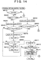
- the third embodiment is further arranged to execute a gradual-return control routine illustrated in the flow chart of Fig. 14, in place of the gradual-return control routine of Fig. 11 used in the first embodiment, when the fuel supply system for any one of the cylinders is diagnosed to be defective. According to the gradual-return control routine of Fig.
- step S912 determines whether fuel supply system for any one of the cylinders is defective. If none of the fuel supply systems for all of the cylinders are defective, that is, if a negative decision (NO) is obtained in step S912, one cycle execution of the routine is terminated. If the fuel supply system for any one of the cylinders is defective, that is, if an affirmative decision (YES) is obtained in step S912, the control flow goes to step S914 in which the suitable remedial operation is performed to deal with the defect.
- step S912 the normal operation of the diesel engine 2 is terminated, and the remedial operation such as the "limp-home" processing is initiated to deal with the defect.
- the limp-home processing is an operation to save data in software to minimize problems which would be caused by the defective fuel supply system.
- the diagnostic change of the cylinder compensation amount qcy[K] is effected only once, and the fuel supply system for a given cylinder is diagnosed to be defective if the speed of the engine does not vary in accordance with the diagnostic change of the compensation amount qcy of that cylinder.
- the accuracy of the diagnosis may be improved by effecting two or more diagnostic gradual changes of the compensation amount qcy[K] of each cylinder.
- the fuel supply system for a given cylinder is diagnosed to be defective only if the speed of the engine does not vary in accordance with all of the two more diagnostic gradual changes of the compensation amount qcy[K].
- the diagnosis may be effected depending upon the number of the diagnostic gradual changes by which the engine speed varies accordingly, and the number of the diagnostic gradual changes by which the engine speed does not vary accordingly.
- the fuel supply system may be diagnosed to be defective if the engine speed does not vary in accordance with any one of the two or more diagnostic gradual changes.
- the fourth embodiment of this invention employs any one of the alternative diagnostic methods described above.
- Apparatus and method for diagnosing a fuel supply system of an internal combustion engine wherein a compensation amount (qcy) for each cylinder is determined on the basis of a deviation (DNE) of an actual operating state of the engine with respect to a desired operating state thereof, and the fuel supply system is feedback-controlled by compensating a commanded value (QFIN) of a quantity of injection of a fuel by the fuel supply system into the internal combustion engine, according to the compensation amount.
- a compensation amount (qcy) for each cylinder is determined on the basis of a deviation (DNE) of an actual operating state of the engine with respect to a desired operating state thereof, and the fuel supply system is feedback-controlled by compensating a commanded value (QFIN) of a quantity of injection of a fuel by the fuel supply system into the internal combustion engine, according to the compensation amount.
- DNE deviation
- QFIN commanded value
- the apparatus and method include respectively include a diagnosing device (52) and a diagnostic step for effecting a diagnostic compulsory adjustment (in steps S590 and S600) of an operating condition of the fuel supply system for each cylinder when the absolute value of the compensation amount (qcy) exceeds a predetermined threshold (A) (when affirmative decision is obtained in step S550), and for diagnosing the fuel supply system on the basis of a speed variation of the engine cause by the adjustment.
Landscapes
- Engineering & Computer Science (AREA)
- Chemical & Material Sciences (AREA)
- Combustion & Propulsion (AREA)
- Mechanical Engineering (AREA)
- General Engineering & Computer Science (AREA)
- Electrical Control Of Air Or Fuel Supplied To Internal-Combustion Engine (AREA)
- Combined Controls Of Internal Combustion Engines (AREA)
Abstract
Description
- The present invention relates to an apparatus and a method for diagnosing a fuel supply system of an internal combustion engine, which is feed-back controlled by compensating a commanded value of a quantity of fuel supply to the engine according to a compensation amount determined on the basis of a deviation of an actual operating state of the engine with respect to a desired operating state of the engine, so that the engine is operated in the desired operating state.
- JP-B2-2907001 discloses an apparatus arranged to lean-burn combustion of a lean-burn gasoline engine and diagnose the engine for abnormality, such that each cylinder of the engine is diagnosed for its combustion state by detecting a variation of a rotation speed of the engine, and the fuel supply to each cylinder is compensated so as to reduce the fuel concentration in each cylinder in a good combustion state, and increase the fuel concentration in each cylinder in a poor combustion state. This apparatus is further arranged to check if the compensation of the air/fuel ratio of an air-fuel mixture to increase the fuel concentration has been implemented more than a predetermined number of times, for any of the cylinders of the engine, and determine that the fuel supply system or an ignition system is defective, for each cylinder for which the compensation has been implemented more than the predetermined number of times.
- Thus, the known apparatus described above is arranged to determine that a given cylinder of the engine is defective, where the fuel supply quantity of that cylinder cannot be controlled in a feedback fashion. According to this apparatus, a cylinder to which the fuel supply is completely stopped due to sticking of a fuel injection valve in its closed position, the commanded value of the fuel supply quantity of that cylinder is continuously compensated so as to increase the air/fuel ratio, so that this cylinder is diagnosed to be defective. On the other hand, the feedback control in some specific operating conditions of the engine, for example, during idling of the engine, may permit normal fuel supply to a given cylinder whose fuel injection valve suffers from leakage of the fuel due to poor seating of its valve body or deterioration of its function of adjusting its opening time caused by an increased sliding resistance of the valve body. In operating conditions of the engine other than the specific operating conditions (e.g., during the engine idling), however, the inadequate duration of opening of the fuel injection valve has a considerable influence on the quantity of the fuel supply to the cylinder, and the feedback control may not permit the normal fuel supply to that cylinder depending upon the operating condition of the engine. In this case, the apparatus may not determine that the cylinder is defective, while in fact the fuel supply system for that cylinder is defective.
- Where the compensation of the air/fuel ratio so as to increase the fuel concentration in a given cylinder has been implemented by adjusting its fuel injection valve for more than the predetermined number of time during idling of the engine, the feedback control so as to reflect the compensation amount obtained during the engine idling may permit normal fuel supply to that cylinder, even in the operating conditions of the engine other than some specific operating conditions such as the engine idling, if opening and closing actions of the fuel injection valve are normal
- As described above the known apparatus is not capable of accurately diagnosing the fuel supply system for abnormality or defect, causing not only a risk of a continued operation of the engine in a poor combustion state with the fuel supply system in a defective state, and deteriorated fuel economy and exhaust emission and other problems, but also a risk of erroneous diagnosis that the normally functioning fuel supply system is defective, which erroneous diagnosis prevents a normal operation of the engine.
- The present invention was made in view of the prior art problems discussed above. It is therefore an object of the present invention to provide an apparatus and method which permits accurate diagnosis of a fuel supply system of an internal combustion engine.
- The one object indicated above may be achieved according to a first aspect of this invention, which provides an apparatus for diagnosing a fuel supply system of an internal combustion engine provided with feedback control means for determining a compensation amount for compensating a commanded value of a quantity of injection of a fuel by the fuel supply system into the internal combustion engine on the basis of a deviation of an actual operating state of the internal combustion engine with respect to a desired operating state thereof, and for controlling the fuel supply system in a feedback fashion by compensating said commanded value, according to the compensation amount, so that the internal combustion engine is operated in the desired operating state, the apparatus comprising diagnosing means for diagnosing the fuel supply system by compulsorily effecting a diagnostic adjustment of an operating condition of the fuel supply system when the compensation amount falls outside a predetermined reference range.
- The object indicated above may be achieved according to another aspect of this invention, which provides a method of diagnosing a fuel supply system of an internal combustion engine wherein the fuel supply system is feedback-controlled such that the internal combustion engine is operated in a desired operating state, characterized by comprising the steps of:
- calculating a deviation of an amount of variation of the an actual operating state with respect to a desired amount of variation thereof;
- determining a compensation amount for compensating a commanded value of a quantity of injection of a fuel by the fuel supply system into the internal combustion engine of each of cylinders of the internal combustion engine on the basis of the above-indicated deviation;
- determining whether the determined compensation amount falls outside a predetermined reference range; and
- diagnosing the fuel supply system by interrupting a feedback control of the fuel supply system and compulsorily effecting a diagnostic adjustment of an operating condition of the fuel supply system when the determined compensation amount falls outside the predetermined reference range.
-
- The diagnosing apparatus and method described above are not arranged to diagnose the fuel supply system, depending merely upon whether the compensation amount used for the feedback control of the fuel supply system falls outside the predetermined reference range. Instead, the present diagnosing apparatus and method are arranged to compulsorily effect the diagnostic adjustment of the operating condition of the fuel supply system when the compensation amount falls outside the predetermined reference range, so that the fuel supply system is diagnosed on the basis of a result of the diagnostic adjustment. The present arrangement to effect the diagnostic operational adjustment of the fuel supply system permits accurate diagnosis of the fuel supply system for not only a sticking defect of a fuel injection valve in the fuel supply system, but also other abnormalities regarding the opening and closing actions of the fuel injection valve, such as deterioration of its function to adjust its opening time. Further, the diagnostic adjustment is effected when the compensation amount is outside the reference range, that is, when there is a high possibility that the fuel supply system is defective. This arrangement permits a further improvement in the accuracy of diagnosis of the fuel supply system.
- Further, the diagnostic adjustment of the operating condition of the fuel supply system effected only when the compensation amount is outside the predetermined reference range prevents an unnecessary change of the combustion state of the internal combustion engine, and minimizes the deterioration of the fuel economy and exhaust emission of the engine, and munimizes the vibration of the engine due to a variation in its operating state.
- According to one preferred form of the present invention, the feedback control means detects an amount of variation of the actual operating state of the internal combustion engine while the internal combustion engine is in an idling state, calculates a the deviation of the amount of variation of the actual operating state in the idling state with respect to a desired amount of variation thereof, determines the compensation amount of each cylinders of the internal combustion engine on the basis of the above-indicated deviation, and compensates the commanded value of the quantity of injection of the fuel by the fuel supply system into each cylinder, according to the determined compensation amount, so that the internal combustion engine is operated in the desired operating state.
- While the fuel supply system for each cylinder of the engine is feedback-controlled by the feedback control means described just above, the diagnosing means effects the diagnostic adjustment of the operating condition of the fuel supply system when the compensation amount determined on the basis of the deviation between the actual and desired amounts of variation of the operating state of the fuel supply system falls outside the predetermined reference range, so that the fuel supply system is diagnosed on the basis of a result of the diagnostic adjustment.
- The above-described arrangement permits accurate diagnosis of the fuel supply system for each cylinder of the engine. The accuracy of diagnosis is further improved since the diagnostic adjustment is effected only when the compensation amount of each cylinder is outside the reference range, that is, only when there is a high possibility that the fuel supply system is defective.
- In addition, the diagnostic adjustment of the operating condition of the fuel supply system effected only when the compensation amount of each cylinder is outside the reference range prevents an unnecessary change of the combustion state of the internal combustion engine, and minimizes the deterioration of the fuel economy and exhaust emission of the engine, and minimizes the vibration of the engine due to a variation in its operating state.
- In a first advantageous arrangement of the apparatus according to the above-indicted preferred form of the invention, the diagnosing means is operable when the compensation amount of any one of the cylinders falls outside the predetermined reference range, to terminate an operation of the feedback control means and effect the diagnostic adjustment of the operating condition of the fuel supply system for the above-indicated any one of the cylinders.
- The diagnosing means described just above is arranged to terminate the feedback control operation by the feedback control means and effect the diagnostic adjustment of the fuel supply system for the cylinder whose compensation amount has become outside the reference range. This arrangement permits efficient and accurate diagnosis of the fuel supply system.
- In a second advantageous arrangement of the apparatus according to the above-indicated preferred form of the invention, the diagnosing means is operable when the compensation amount of any one of the cylinders falls outside the predetermined reference range, to terminate an operation of the feedback control means and effect the diagnostic adjustments of the operating conditions of the fuel supply systems for selected ones of the cylinders of the internal combustion engine, which selected ones include the above-indicated any one cylinder.
- The diagnosing means described just above is arranged to terminate the feedback control operation by the feedback control means and effect the diagnostic adjustments of the fuel supply systems for the selected cylinders include the cylinder whose compensation amount has become outside the reference range. According to this arrangement, only the fuel supply systems for the selected cylinders, which include the fuel supply system relatively likely to be defective, are diagnosed by effecting the diagnostic adjustments of those fuel supply systems. Accordingly, the present arrangement not only permits efficient and accurate diagnosis, but also effectively prevents an unnecessary change of the combustion state of the internal combustion engine, while minimizing the deterioration of the fuel economy and exhaust emission of the engine, and minimizes the vibration of the engine due to a variation in its operating state.
- In the apparatus and method according to the above-indicated preferred form of the invention, the diagnosing means may be arranged to be operable to effect a diagnostic compulsory increase or reduction of the compensation amount of each of selected at least one of cylinders of the internal combustion engine, and diagnosing the fuel supply system for each selected cylinder, on the basis of a variation in the actual operating state of the internal combustion engine which is caused by the diagnostic compulsory increase or reduction of the compensation amount.
- In the apparatus described just above, the fuel supply system for each of the selected cylinders of the engine is diagnosed on the basis of the variation in the actual operating state of the engine which is caused by the diagnostic compulsory increase or reduction of the compensation amount by the diagnosing means. This arrangement permits higher degrees of efficiency and accuracy of the diagnosis.
- In the apparatus and method described just above, the diagnosing means may be arranged to be operable to diagnose the fuel supply system for each selected cylinder to be normal when the actual operating state of the internal combustion engine varies in accordance with the diagnostic compulsory increase or reduction of the compensation amount, and defective or abnormal when the actual operating state does not vary in accordance with the diagnostic compulsory increase or reduction of the compensation amount.
- Where the operating state of the fuel supply system such as the opening and closing actions of its fuel injection valve is normal, the actual operating state of the internal combustion engine varies in accordance with the diagnostic increase or reduction of the compensation amount of each selected cylinder. In view of this fact, the diagnosing means may be arranged to diagnose the fuel supply system to be normal if the actual operating state of the engine varies in accordance with the diagnostic compulsory increase or reduction of the compensation amount, and defective or abnormal if the actual operating state of the engine does not vary in accordance with the diagnostic compulsory increase or reduction of the compensation amount.
- The compensation amount may be gradually increased or reduced when the diagnostic increase or reduction is compulsorily executed.
- The compensation amount may be gradually returned to an original value after the diagnostic increase or reduction of the compensation amount is compulsorily executed.
- The above and other objects, features, advantages and technical and industrial significance of the present invention will be better understood by reading the following detailed description of presently preferred exemplary embodiments of the invention, when considered in connection with the accompanying drawings, in which:
- Fig. 1 is a schematic view showing a diesel engine of common-rail type, and a control system arranged according to a first embodiment of this invention for controlling the diesel engine;
- Fig. 2 is a flow chart illustrating a fuel-injection quantity control routine executed by an ECU of the control system of the first embodiment;
- Fig. 3 is a flow chart illustrating a cylinder-compensation-amount calculating routine executed for each cylinder of the engine, in the first embodiment;
- Fig. 4 is an illustration of an arrangement of an engine speed sensor and a pulser used in the first embodiment;
- Fig. 5 is a time chart depicting a variation of the rotation speed of the common-rail type diesel engine, in the first embodiment;
- Fig. 6 is a graph indicating a data map used in the cylinder-compensation-amount calculating routine of Fig. 3, to calculate an integral compensating amount dqcy on the basis of a speed variation DNE(K);
- Fig. 7 is a flow chart illustrating a portion of a preliminary-diagnosis routine executed by the ECU of the control system of the first embodiment, to effect a preliminary diagnosis of the fuel supply system;
- Fig. 8 is a flow chart illustrating the other portion of the preliminary-diagnosis routine;
- Fig. 9 is a flow chart illustrating a portion of a main-diagnosis routine executed in the first embodiment, to effect a main diagnosis of the fuel supply system;
- Fig. 10 is a flow chart illustrating the other portion of the main-diagnosis routine;
- Fig. 11 is a flow chart illustrating a gradual-return control routine executed in the first embodiment;
- Fig. 12 is a time chart depicting an example of various parameters whose values change during the control effected in the first embodiment;
- Fig. 13 is a flow chart illustrating a fuel-supply-system diagnostic routine executed in a third embodiment of the present invention; and
- Fig. 14 is a flow chart illustrating a gradual-return control routine executed in the third embodiment.
-
- Referring to the accompanying drawings, the presently preferred embodiments of this invention will be described in detail.
- Referring first to the schematic view of Fig. 1, there are shown a
diesel engine 2 of common-rail type, and a control system arranged according to the first embodiment of the present invention, for controlling thediesel engine 2. Thediesel engine 2 is adapted to be installed as a drive power source on an automotive vehicle. - The
diesel engine 2 has a plurality of cylinders, more precisely, four cylinders #1-#4, in this specific embodiment. In Fig. 1, only one of the four cylinders #1-#4 is shown. Each cylinder is provided with afuel injection valve 4 arranged to inject fuel into its combustion chamber. Thefuel injection valve 4 is provided with anelectromagnetic control valve 4a which is opened to permit thefuel injection valve 4a to inject the fuel into the corresponding cylinder and closed to inhibit the fuel injection. Although the present embodiment as applied to the four-cylinder diesel engine 2 will be described, the same embodiment is equally applicable to not only the diesel engine but also gasoline engines, and also applicable to a diesel or gasoline engine having six cylinders or any other number of cylinders as well as a four-cylinder engine. - Each
fuel injection valve 4 is connected to a common rail 6, which functions an accumulator commonly for the four cylinders #1-#4. While theelectromagnetic control valve 4a indicated above is held open, the fluid delivered from the common rail 6 is injected into the corresponding cylinder through the correspondingfuel injection valve 4. The common rail 6 is kept charged with the pressurized fuel, the pressure of which is high enough to permit the fuel injection into each cylinder. To keep the fuel pressure in the common rail 6 at a desired level, the common rail 6 is connected through a supply tube 8 to adischarge portion 10a of afuel supply pump 10. Thefuel supply pump 10 is connected to afuel tank 12 through asuction port 10b. A passage connecting thesuction port 10b and thefuel tank 12 is provided with a filter 14. Thefuel supply pump 10 includes a plunger which is reciprocated by a drive cam (not shown) which is rotated in synchronization with a rotary motion of thediesel engine 2. With thefuel supply pump 10 thus operated, the fuel received from thefuel tank 12 through the filter 14 is pressurized by thefuel supply pump 10 to the desired level, and the thus pressurized fuel is delivered to the common rail 6. - The combustion chamber of each cylinder of the
diesel engine 2 is connected to an intake passage 18 and anexhaust passage 20, and a throttle valve (not shown) is provided in the intake passage 18. The angle of opening of this throttle valve is controlled depending upon the operating state of thediesel engine 2, to thereby a rate of flow of the intake air into the combustion chamber. - The combustion chamber of each cylinder of the
diesel engine 2 is provided with aglow plug 22, which is energized with an electric current applied thereto from a glow-plug relay 22a immediately before thediesel engine 2 is started. Upon energization of theglow plug 22, a spray mist of the fuel blown over theglow plug 22 is easily ignited, and the combustion of the fuel is promoted. Thus, theglow plug 22 serves as a device for assisting the starting of thediesel engine 2. - To monitor the operating state of the
diesel engine 2 in the present embodiment, there are provided the following sensors. Namely, anaccelerator sensor 26 is disposed near anaccelerator pedal 24, for detecting an operating amount ACCPF of theaccelerator pedal 24, and an accelerator-OFF switch 28 is disposed near theaccelerator sensor 26, to detect that theaccelerator pedal 24 is at rest, that is, is placed in its non-operated position. Thediesel engine 2 is further provided with astarter 30 for starting the engine. Thisstarter 30 is provided with astarter switch 30a for detecting its operating state. Thediesel engine 2 is also provided with awater temperature sensor 32 disposed on its cylinder block, for detecting a temperature THW of a cooling water flowing through the cylinder block. Thediesel engine 2 has an oil pan (not shown) in which an engine oil is stored, and is provided with anoil temperature sensor 34 for detecting a temperature THO of the engine oil in the oil pan. Areturn tube 16 connected to thefuel tank 12,fuel supply pump 10 andfuel injection valve 4 is provided with afuel temperature sensor 36 for detecting a temperature THF of the fuel. The common rail 6 is provided with afuel pressure sensor 38 for detecting the pressure of the fuel within the common rail 6. The crankshaft (not shown) of thediesel engine 2 is provided with apulser 41, and anengine speed sensor 40 for detecting the rotation speed of theengine 2 is disposed near thepulser 41, as shown in Fig. 4. - A rotary motion of the crankshaft is transmitted through a timing belt to a cam shaft (not shown) provided to open and close an
intake valve 18a and anexhaust valve 20a. This cam shaft is rotated at a speed which is one half the rotating speed of the crankshaft. Near a pulser (not shown) disposed on the cam shaft, there is disposed acylinder detecting sensor 42. In the first embodiment of this invention, output signals of theengine speed sensor 40 and thecylinder detecting sensor 42 are used to calculate the speed NE and a crank angle CA of thediesel engine 2, and a top dead center (TDC) of thecylinder # 1. The vehicle has atransmission 44, which is provided with ashift position sensor 46 for detecting the presently selected one of the operating positions of thetransmission 44 and anoutput speed sensor 48 for detecting the rotating speed of an output shaft of thetransmission 44. The output signal of theoutput speed sensor 48 is used to calculate a running speed SPD of the vehicle. The vehicle also has an air conditioner (not shown) which is driven by thediesel engine 2 and which is turned on and off by anair conditioner switch 50. - To effect various controls of the
diesel engine 2, there is provided an electronic control unit (ECU) 52 arranged according to the present embodiment of the invention. TheECU 52 is arranged to effect a fuel-injection control, a glow-plug control and other controls of thediesel engine 2, and is further arranged to effect diagnostic controls to diagnose the fuel supply system of each cylinder. TheECU 52 is principally constituted by a microcomputer incorporating: a central processing unit (CPU); a read-only memory (ROM) storing various control programs and data maps; a random-access memory (RAM) for temporarily storing various sorts of data such as those obtained by arithmetic operations by the CPU; a back-up RAM for storing arithmetic operation data and prepared data; time counters; an input interface; and an output interface. To the input interface of theECU 52, there are connected the above-describedaccelerator sensor 26,water temperature sensor 32,oil temperature sensor 34,oil temperature sensor 36,fuel pressure sensor 38, etc. through buffers, multiplexers and A/D converters (not shown). Also connected to the input interface are theengine speed sensor 40,cylinder detecting sensor 42,output speed sensor 48, etc. through waveform shaping circuits (not shown). The accelerator-OFF switch 28,starter switch 30a, shiftposition sensor 46,air conditioner switch 50, etc. are directly connected to the input interface of theECU 52. The input interface of theECU 52 further receives a signal indicative of a battery voltage Vb and a signal indicative of a duty ratio DF of an alternator (not shown) provided for thediesel engine 2. The CPU reads in the output signals of the above-described sensors and switches which are received through the input interface. To the output interface of theECU 52, there are connected through driver circuits the above-indicatedelectromagnetic control valve 4a and glow-plug relay 22a, and apressure control valve 10c provided for controlling the delivery pressure of thefuel supply pump 10. The CPU operates to perform arithmetic operations on the basis of the signals received through the input interface, and suitably control theelectromagnetic control valve 4a,pressure control valve 10c,glow relay 22a, etc., through the output interface. - Referring next to the flow chart of Fig. 2, there is illustrated a fuel-injection control routine executed by the
ECU 52. This fuel-injection control routine is repeatedly executed as an interruption routine with a cycle time corresponding to a predetermined amount of change of the crank angle CA of theengine 2, more precisely, with a cycle time corresponding to a change of the crank angle CA by 180°, in the present embodiment in which theengine 2 has the four cylinders. In the fuel-injection control routine of Fig. 2 and other routines which will be described, steps of performing respective control operations are identified by respective step numbers preceded by alphabetic letter "S". - The fuel-injection control routine of Fig. 2 is initiated with step S110 to calculate a commanded value QFIN of a fuel injection quantity Q on the basis of the engine speed NE and accelerator operating amount ACCPF, and according to a predetermined equation. Step S110 is followed by step S120 in which the commanded value QFIN of the fuel injection quantity is compensated according to the following equation (1), on the basis of a cylinder compensation amount qcy[K] which has been calculated in a cylinder-compensation-amount calculating routine (which will be described by reference to the flow chart of Fig. 3), for a presently selected cylinder #K into which the fuel is to be injected.
electromagnetic control valve 4a of thefuel injection valve 4 provided for the presently selected cylinder #K, on the basis of the thus compensated commanded value QFIN of fuel injection quantity. Thus, one cycle of execution of the routine of Fig. 2 is terminated. - With the fuel-injection control routine of Fig. 2 being repeatedly executed, appropriate quantities of fuel are successively injected from the
fuel injection valves 4 into the respective individual cylinders which are to be sequentially supplied with the fuel in a predetermined order. Thus, the quantities of the fuel supplied to the cylinders are suitably controlled depending upon the specific operating condition of the vehicle. - Then, the above-indicated cylinder-compensation-amount calculating routine will be described by reference to the flow chart of Fig. 3. Like the fuel-injection control routine of Fig. 2, the present routine is repeatedly executed as an interruption routine with a cycle time corresponding to the predetermined amount of change of the crank angle CA, more precisely, with a cycle time corresponding to a change of the crank angle CA by 180°, in the present embodiment in which the
engine 2 has the four cylinders. The cylinder-compensation-amount calculating routine of Fig. 3 is initiated with step S200 to determine whether a CALCULATION PERMIT flag Xqcy is in an ON state. If the flag Xqcy is in an OFF state, that is, if a negative decision (NO) is obtained in step S200, one cycle of execution of the routine is terminated. - If the flag Xqcy is in the ON state, that is, if an affirmative decision (YES) is obtained in step S200, the control flow goes to step S210 to determine whether the
diesel engine 2 is in a stable idling state. The stabling idling state of thediesel engine 2 is interpreted to mean an idling state in which the vehicle speed SPD is 0km/h and the idling speed of thediesel engine 2 is stabilized with an elapse of a sufficiently long time after theaccelerator pedal 24 has been returned to its fully released or non-operated position (at which the operating amount ACCPF is 0% and the accelerator-OFF switch 28 is in the ON state. - If the
diesel engine 2 is not in the stable idling state, that is, if a negative decision (NO) is obtained in step S210, one cycle of execution of the routine of Fig. 3 is terminated. If thediesel engine 2 is in the stable idling state, that is, if an affirmative decision (YES) is obtained in step S210, the control flow goes to step S220 to determine whether the presently detected engine speed NE is substantially equal to a desired idling speed NF, namely, whether the actual engine idling speed NE is held within a predetermined reference range determined by the desired idling speed NF. This step S220 is implemented for the purpose of determining whether an external device to be driven by thediesel engine 2, such as a compressor of the air conditioner, has been just turned on or off. If the external device has been just turned on or off, the actual engine speed NE changes to a value outside the predetermined reference range which includes the desired idling speed NF, that is, the actual engine speed NE is not stabilized. The actual engine speed NE is stabilized while being held within the predetermined reference range, unless the external device has just been turned on or off. - If the actual engine speed NE is not substantially equal to the desired idling speed NF, that is, if a negative decision (NO) is obtained in step S220, one cycle of execution of the present routine is terminated. If the actual engine speed NE is substantially equal to the desired idling speed NF, that is, if an affirmative decision (YES) is obtained in step S220, on the other hand, the control flow goes to step S230 to calculate a speed variation DNE[K] of the presently selected cylinder #K (into which the fuel is to be injected), according to the following equation:
- In the above equation (2), TNH[K] represents a value in dependence on the maximal speed of the presently selected cylinder #K (hereinafter referred to as "cylinder maximal speed), and TNH[K-1] represents a value corresponding to the maximal speed of the cylinder #K-1 the combustion stroke of which takes place one stroke before that of the presently selected cylinder #K. The values TNH[K] and TNH[K-1], which will be later described in detail, are inversely or reciprocally proportional to the speed NE of the
diesel engine 2. - That is, the value TNH represents a time duration during which a predetermined number of successive pulse signals are generated by the
engine speed sensor 40 in cooperation with thepulser 41 shown in Fig. 4. Described in detail, theengine speed sensor 40 including an electromagnetic pick-up coil is disposed in the toothed outer circumferential surface of the wheel of thepulser 41 attached to the crankshaft of thediesel engine 2. Theengine speed sensor 40 generates a pulse signal each time one tooth formed on the wheel of the pulser 41 passes theengine speed sensor 40 during rotation of the crankshaft. TheECU 52 calculates the rotation speed NE of thediesel engine 2 on the basis of the pulse signals generated by theengine speed sensor 40. The wheel of thepulser 41 has a total of 36 tooth positions equiangularly spaced apart from each other in its circumferential direction at an angular interval of 10 °. However, the wheel of thepulse 41 has a total of 34 teeth in the absence of teeth at two successive ones of the 36 tooth positions, that is, in the presence of a non-toothedcircumferential portion 41a corresponding to those two successive tooth positions. During an operation of thediesel engine 2, one pulse signal is generated per each change of the crank angle CA by 10° and per each tooth of thepulse 41, namely, the pulse signals are generated by theengine speed sensor 40 at an angular spacing interval of 10° of the teeth of thepulser 41, as indicated in Fig. 5, in which the pulse signals after their waveforms have been shaped are shown. It is noted that the pulse-to-pulse interval at thenon-toothed portion 41a corresponds to 30°, and this comparatively large pulse-to-pulse interval corresponding to thenon-toothed portion 41a appears for each change of the crank angle CA by 360°, that is, for each full rotation of the crankshaft. Thecylinder detecting sensor 42 is arranged to detect a reference angular position of the cam shaft corresponding to the top dead center (TDC) of thecylinder # 1, on the basis of the pulse signals generated by theengine speed sensor 40 and thecylinder detecting sensor 42, as described above, and the crank angle CA is obtained with respect to the detected top dead center of thecylinder # 1. - Since the value TNH[K] represents the time duration during which the predetermined number of successive pulse signals are generated by the
engine speed sensor 40, the value TNH[K] is smaller than the value TNH[K-1] when the maximal speed of the presently selected cylinder #K is higher than that of the cylinder #K-1. In this case, therefore, the speed variation DNE[K] calculated according to the above equation (2) is a negative value. When the maximal speed of the presently selected cylinder #K is lower than that of the cylinder #K-1, on the other hand, the value TNH[K] is larger than the value TNK[K-1]. In this case, therefore, the speed variation DNE[K] is a positive value. - Described more specifically, the maximal speed of each cylinder is presented by the time duration TNH of the predetermined number of successive pulse signals, namely, three pulse signals in the specific example of Fig. 5. This time duration TNH of the three pulse signals is a time interval between the moments of rise of the first and fourth ones of four successive pulse signals which include the above-indicated three pulse signals and which are generated by the
engine speed sensor 40 at respective four different crank angles CA (respective four angular positions of the crankshaft) which are equally spaced from each other. That is, those four pulse signals are generated at the respective crank angles CA corresponding to the maximal speed of each cylinder, as indicated in the graph of Fig. 5. Accordingly, the value DNE[K] calculated according to the above equation (2) represents a difference between the maximal speeds of the two cylinders #K and #K-1, that is, a speed variation of the presently selected cylinder #K with respect to the speed of the preceding cylinder #K-1. - After the speed variation DNE[K] has been calculated as described above, the control flow goes to step S240 to calculate an integral compensation amount dqcy on the basis of the speed variation DNE[K] and according to a graph shown in Fig. 6. This graph represents a relationship between the integral compensation amount dqcy and the speed variation DNE[K], and is formulated such that the integral compensation amount dqcy increases with an increase of the speed variation DNE[K]. y
- The control flow then goes to step S250 in which the cylinder compensation amount qcy[K] is updated on the basis of the thus calculated integral compensation amount dqcy and according to the following equation (3):
- Thus, the integral compensation amount dqcy is added to the cylinder compensation qcy[K] when the speed variation of the successive two cylinders #K and #K-1 of the
diesel engine 2, and the thus updated cylinder compensation amount qcy[K] is used in step S120 of the fuel injection control routine of Fig. 2, to compensate the commanded value QFIN of the fuel injection quantity of each of the four cylinders, so as to eliminate the speed variation of thediesel engine 2, so that the fuel supply system is feedback-controlled so as to minimize a variation of the rotation speed of thediesel engine 2. - Where the speed variation DNE[K] of the presently selected cylinder #K is a negative value, that is, the speed of the
diesel engine 2 as a result of combustion in the presently selected cylinder #K is higher than that as a result of combustion in the preceding cylinder #K-1, the integral compensation amount dqcy is a negative value, so that the cylinder compensation amount qcy[K] is reduced by the integral compensation amount dqcy. Consequently, the commanded fuel injection quantity value QFIN for the presently selected cylinder #K is reduced by the compensation in step S120. - Where the speed variation DNE[K] of the cylinder #K is a positive value, that is, the speed of the
diesel engine 2 as a result of combustion in the present cylinder #K is lower than that as a result of combustion in the preceding cylinder #K-1, the integral compensation amount dqcy is a positive value, so that the cylinder compensation amount qcy[K] is increased by the integral compensation amount dqcy. Consequently, the commanded fuel injection quantity value QFIN for the present cylinder #K is increased by the compensation in step S120. - When the absolute value of the speed variation DNE[K] is comparatively small, that is, the speed as a result of combustion in the present cylinder #K and the speed as a result of combustion in the preceding cylinder #K-1 are almost equal to each other, the integral compensation amount dqcy is almost zero, and the cylinder compensation amount qcy[K] remains substantially unchanged, so that the commanded value QFIN of the fuel injection quantity of the present cylinder #K remains substantially constant.
- Referring next to the flow charts of Figs. 7-10, there will next be described a preliminary-diagnosis routine and a main-diagnosis routine. The preliminary-diagnosis routine is illustrated in the flow charts of Figs. 7 and 8. This routine is repeatedly executed per each change of the crank angle CA by 180°.
- The preliminary-diagnosis routine is initiated with step S310 to determine whether the
diesel engine 2 is in the stable idling state. This step S310 is identical with the step S210 in the cylinder-compensation-amount calculating routine of Fig. 3. If thediesel engine 2 is in the stable idling state, that is, if an affirmative decision (YES) is obtained in step S310, the control flow goes to step S320 to determine whether the detected engine speed NE is substantially equal to the desired idling speed NF. This step S320 is identical to the step S220 of the cylinder-compensation-amount calculating routine of Fig. 2. - If a negative decision (NO) is obtained in step S310 or S320, the control flow goes to step S330 to reset a DELAY counter Dcnt. If an affirmative decision (YES) is obtained in both of the steps S310, S320, the control flow goes to step S340 to increment the DELAY counter Dcnt. Thus, the content of the DELAY counter Dcnt represents a period of time during which the
diesel engine 2 has been in the stable idling state with its speed NE being held substantially equal to the desired idling speed NF. More precisely, the content of the DELAY counter Dcnt represents a cumulative number of rotations of the crankshaft while thediesel engine 2 is held in the stable idling state with its speed NE being held substantially equal to the desired idling speed NF. - Step S330 and S340 are followed by step S350 to determine whether the content of the DELAY counter Dcnt is larger than a threshold value Td. This threshold value Td provides a period of time necessary to obtain the cylinder compensation amounts qcy[K] of all of the four cylinders, by repeated implementation of steps S230-S250 in the cylinder-compensation-amount calculating routine of Fig. 3.
- If the content of the DELAY counter Dcnt is equal to or smaller than the threshold Td, that is, if a negative decision (NO) is obtained in step S350, the control flow goes to step S370. In step S370 a cylinder identification value "k" is set to 1. "k" identifies the cylinder whose compensation amount qcy[K] is to be diagnosed. In this case, one cycle of execution of the routine is terminated. When the content of the DELAY counter Dcnt has exceeded than the threshold Td as a result of repeated incrementing operations of the DELAY counter Dcnt while the
diesel engine 2 is held in the stable idling state with its speed substantially equal to the desired idling speed NF, that is, when an affirmative decision (YES) is obtained in step S350 as a reslt of the repeated incrementing operations of the counter Dcnt after the affirmative decisions (YES) are repeatedly obtained in steps S310 and S320, the control flow goes to step S380 to determine whether an UNDER-DIAGNOSIS flag Xtst is in an OFF state. Since this flag Xtst is initially set in the OFF state, that is, since an affirmative decision (YES) is obtained in step S380 in the first cycle of execution of the present preliminary-diagnosis routine, the control flow goes to step S390 to determine whether the cylinder compensation amount qcy[K] obtained in step S250 of the cylinder-compensation-amount calculating routine of Fig. 3 is equal to or larger than zero. Since the cylinder identification value "k" is initially set to "1", the compensation value qcy[1] of thecylinder # 1 is checked. - If the cylinder compensation amount qcy[K] is equal to or larger than zero, that is, if an affirmative decision (YES) is obtained in step S390, the control flow goes to step S400 to set a SIGN flag explus[k] in an ON state. In the first cycle, the SIGN flag explus[1] is set in the ON state. If the cylinder compensation amount qcy[1] is smaller than zero, that is, if a negative decision (NO) is obtained in step S390, the control flow goes to step S410 to set the SIGN flag explus[1] in an OFF state.
- Steps S400 and S410 are followed by step S420 to determine whether the absolute value of the cylinder compensation amount qcy[k] is equal to or smaller than a preliminary-diagnosis threshold A. If absolute value of the compensation amount qcy[1] is equal to or smaller than the threshold A, that is, if an affirmative decision (YES) is obtained in step S420, the control flow goes to step S430 to increment the cylinder identification value "k". In the first cycle of execution of the routine of Figs. 7 and 8, the cylinder identification value "k" is incremented to "2".
- If the absolute value of the compensation amount qcy[1] is larger than the threshold A, that is, if a negative decision (NO) is obtained in step S420, the control flow goes to step S440 to set the UNDER-DIAGNOSIS flag in the ON state. Step S440 is followed by step S430 to increment the cylinder identification value "k".
- Step S430 is followed by step S450 to determine whether the cylinder identification value "k" is equal to or smaller than "4". In this respect, it is noted that the
diesel engine 2 has the four cylinders #1-#4. Since the cylinder identification value "k" is now equal to "2", an affirmative decision (YES) is obtained in step S450, and the control flow returns to step S390. Steps S390-S450 are repeated to check the compensation amount qcy[2] of the cylinder #2 (identified by the value "k" = 2) the combustion stroke of which takes place following that of the cylinder #1 (identified by the value "k" = 1). After the steps S390-S450 have been repeated for the compensation amount qcy[2], these steps are further repeated for the compensation amounts qcy[3] and qcy[4] of the followingcylinders # 3 and #4. - When the cylinder identification value "k" has been incremented to "5", that is, when a negative decision (NO) is obtained in step S450, the control flow goes to step S470 to determine whether the UNDER-DIAGNOSIS flag Xtst is now placed in the ON state. If the flag Xtst is placed in the OFF state, that is, if a negative decision (NO) is obtained in step S470, the control flow goes to step S475 to reset the DELAY counter Dcnt to "0", and one cycle of execution of the routine is terminated. The UNDER-DIAGNOSIS flag Xtst in the OFF state indicates that the values |qcy[k]| of all of the four cylinders are equal to or smaller than the threshold A, that is, the affirmative decision (YES) was obtained in step S420 for all of the four cylinders. In this case, the DELAY counter Dcnt is reset to "0", and the preliminary-diagnosis routine of Figs. 7-8 is executed again.
- If the PRELIMINARY-DIAGNOSIS flag Xtst is set in the ON state, that is, if an affirmative decision (YES) is obtained in step S470, this indicates that the absolute value of the compensation amount qcy[k] is larger than the threshold A for at least one of the four cylinders #1-#4. In this case, the control flow goes to step S480 to reset an addition-subtraction term dtst to "0". The term dtst will be described below. Then, step S490 is implemented to store the presently obtained cylinder compensation amounts qcy[1], qcy[2], qcy[3] and qcy[4] as respective variables qcyorg[1], qcyorg[2], qcyorg[3] and qcyorg[4], and one cycle of execution of the routine is terminated.
- In the next cycle of execution of the routine after steps S470-S490, a negative decision (NO) is obtained in step S380 since the UNDER-DIAGNOSIS flag Xtst is set in the ON state, and this cycle is terminated. As long as the flag Xtst is kept in the ON state, steps S390-S490 are not implemented even if the affirmative decision (YES) is maintained in steps S310, S320 and S350.
- Then, the main-diagnosis routine will be described by reference to the flow chart of Figs. 9 and 10. This routine is also executed with a cycle time corresponding to a change of the crank angle CA by 180°. The present main-diagnosis routine is initiated with step S500 to determine whether a GRADUAL RETURN flag Xret is set in an OFF state. Since this flag is initially set in the OFF state, an affirmative decision (YES) is obtained in the first cycle of execution of the routine, and the control flow goes to step S510 to determine whether the
diesel engine 2 is in the stable idling state. This step S510 is identical with the step S210 in the cylinder-compensation-amount calculating routine of Fig. 3. If thediesel engine 2 is in the stable idling state, that is, if an affirmative decision (YES) is obtained in step S510, the control flow goes to step S520 to determine whether the detected engine speed NE is substantially equal to the desired idling speed NF. This step S520 is identical with the step S220 in the cylinder-compensation-amount calculating routine of Fig. 3. - If a negative decision (NO) is obtained in step S510 or S520, the control flow goes to step S525 to set the UNDER-DIAGNOSIS flag Xtst in the OFF state, and then goes to step S526 to reset the DELAY counter Dcnt to "0". Step S526 is followed by step S530 to set the CALCULATION PERMIT flag Xqcy in the ON state, and step S540 to increment a cylinder identification value "m", namely, to set the value "m" to "1" in the first cycle of execution of the routine. Thus, one cycle of execution of the routine is terminated. In this case wherein the flag Xtst is set in the OFF state, the affirmative decision (YES) is obtained in step S380 in the preliminary-diagnosis routine of Figs. 7 and 8, and steps S390-S490 may be implemented. Further, since the flag Xqcy is set in the ON state, the affirmative decision (YES) is obtained in step S200 of the cylinder-compensation-amount calculating routine of Fig. 3, and the cylinder compensation amount qcy[K]may be updated in step S240.
- If the
diesel engine 2 is in the stable idling state with its speed NE being substantially equal to the desired idling speed, that is, if an affirmative decision (YES) is obtained in steps S510 and S520, the control flow goes to step S550 to determine whether the UNDER-DIAGNOSIS flag Xtst is in the ON state. If the flag Xtst is in the OFF state, that is, if a negative decision (NO) is obtained in step S550, the control flow goes to step S530 to set the CALCULATION PERMIT flag Xqcy in the ON state. Step S530 is followed by step S540 to set the value "m" to "1", and one cycle of execution of the routine is terminated. - If the flag Xtst is in the ON state, that is, if an affirmative decision (YES) is obtained in step S550, the control flow goes to step S560 to set the CALCULATION PERMIT flag Xqcy in the OFF state. In this case, the negative decision (NO) is obtained in step S200 in the cylinder-compensation-amount calculating routine of Fig. 3, so that the cylinder compensation amount qcy[K] of each cylinder is not updated in the routine of Fig. 3.
- Then, step S570 is implemented to calculate the addition-subtraction term dtst according to the following equation (4):
- Then, the control flow goes to step S580 to determine whether the SIGN flag explus[m] is in the ON state. In the first cycle of execution of the routine, the value "m" is equal to "1", a determination as to whether the SIGN flag explus[1] is in the ON state. If the flag explus[1] is in the ON state, that is, if an affirmative decision (YES) is obtained in step S580, the control flow goes to step S590 to update the cylinder compensation amount qcy[m] according to the following equation (5):
- If the flag explus[m] is in the OFF state, that is, if a negative decision (NO) is obtained in step S580, the control flow goes to step S600 to update the cylinder compensation amount qcy[m] according to the following equation (6):
- Thus, when the cylinder compensation amount qcy[m] is equal to or larger than zero, this amount qcy[m] is reduced by the gradually increasing addition-subtraction term dtst, so that the actual fuel injection quantity is gradually reduced. When the cylinder compensation amount qcy[m] is smaller than zero, this amount qcy[m] is increased by the gradually increasing addition-subtraction term dtst, so that the actual fuel injection quantity is gradually increased.
- Steps S590 and S600 are followed by step S610 to calculate the speed variation DNE[m] according to the following equation (7):
- Step S610 is followed by step S620 to determine whether the absolute value of the speed variation DNE[m] is larger than a threshold B. If the value |DNE[m] | is equal to or smaller than the threshold B, that is, if a negative decision (NO) is obtained in step S620, the control flow goes to step S630 to determine whether the addition-subtraction term dtst is larger than a threshold D. If the value dtst is equal to or smaller than the threshold D, that is, if a negative decision (NO) is obtained in step S630, one cycle of execution of the present routine is terminated. Accordingly, the cylinder compensation amount qcy[m] is gradually changed as long as the absolute value of the speed variation DNE[m] is equal to or smaller than the threshold B and the addition-subtraction term dtst is equal to or smaller than the threshold D, that is, as long as the negative decision (NO) is obtained in steps S620 and S630, while the fuel injection quantity is gradually increased or reduced by implementation of steps S590 and S600. In other words, the commanded value QFIN of the fuel injection quantity of each cylinder is gradually increased or reduced by the gradual increase or reduction of the cylinder compensation amount qcy[K] which has been described with respect to step S120 in the fuel-injection control routine of Fig. 2 and which is calculated according to the above equation (1).
- If the value |DNE[m] | has become larger than the threshold B before the term dtst has become larger than the threshold D, that is, if an affirmative decision (YES) is obtained in step S620 before an affirmative decision (YES) is obtained in step S630, with an increase of the speed variation DNE[m] as a result of the gradual change of the cylinder compensation amount qcy[m], it means that the speed variation DNE[m] has increased as expected owing to a change of the cylinder compensation amount qcy[m] based on the addition-subtraction term dtst. In this case, therefore, the control flow goes to step S640 to diagnose that the fuel supply system for the cylinder #m is normal. Step S640 is followed by step S650 to increment the cylinder identification value "m". If the fuel supply system for the
cylinder # 1 is diagnosed to be normal, the value "m" is incremented to "2". - Step S650 is followed by step S660 to determine whether the cylinder identification value "m" is equal to or smaller than "4". Since the value "m" is now equal to "2", an affirmative decision(YES) is obtained in step S660, and the control flow goes to step S670 to reset the addition-subtraction term dtst to "0". Step S680 is then implemented to reset the GRADUAL RETURN flag Xret to the ON state, and one cycle execution of the routine is terminated.
- In the next cycle of execution of the routine of Figs. 9 and 10, the flag Xret is set in the ON state, that is, a negative decision (NO) is obtained in step S500, no operation is practically performed. In this case, a gradual-return control routine (which will be described) is executed to gradually return the cylinder compensation amount qcy[1] to the original value qcyorg[1].
- After the cylinder compensation amount qcy[1] has been returned to the original value qcyorg[1], the GRADUAL RETURN flag Xret is reset to the OFF state in the gradual-return control routine, so that the affirmative decision (YES) is obtained in step S500. Accordingly, the operation described above is repeated for the
cylinder # 2. Described in detail, the compensation amount qcy[2] for thecylinder # 2 is gradually increased or reduced in steps S590, S600 depending upon the state of the SIGN flag explus[2], and the determination as to whether the absolute value of the speed variation DNE[2] is larger than the threshold B is made in step S620. - If the value |DNE[2]| has become larger than the threshold B before the term dtst has become larger than the threshold D, that is, if the affirmative decision (YES) is obtained in step S620 before the affirmative decision (YES) is obtained in step S630, with an increase of the speed variation DNE[2] as a result of the gradual change of the cylinder compensation amount qcy[2], it means that the speed variation DNE[2] has increased as expected owing to a change of the cylinder compensation amount qcy[2] based on the addition-subtraction term dtst. In this case, therefore, the control flow goes to step S640 to diagnose that the fuel supply system for the
cylinder # 2 is normal. Step S640 is followed by step S650 to increment the cylinder identification value "m" to "3". Since the value "m" is now equal to "3", the affirmative decision (YES) is obtained in step S660, and the control flow goes to step S670 to reset the addition-subtraction value dtst to "0". Step S680 is then implemented to set the GRADUAL RETURN flag to the ON state, and one cycle of execution of the routine is terminated. - In the next cycle of execution of the routine of Figs. 9 and 10, the flag Xret is set in the ON state, that is, the negative decision (NO) is obtained in step S500, so that no operation practically is performed. In this case, the gradual-return control routine (which will be described) is executed to gradually return the cylinder compensation amount qcy[2] to the original value qcyorg[2].
- After the cylinder compensation amount qcy[2] has been returned to the original value qcyorg[2], the GRADUAL RETURN flag Xret is reset to the OFF state in the gradual-return control routine, so that the affirmative decision (YES) is obtained in step S500. Accordingly, the operation described above is repeated for the
cylinder # 3. Described in detail, the compensation amount qcy[3] for thecylinder # 3 is gradually increased or reduced in steps S590, S600 depending upon the state of the SIGN flag explus[3], and the determination as to whether the absolute value of the speed variation DNE[3] is larger than the threshold B is made in step S620. - If the value |DNE[3]| has become larger than the threshold B, that is, if the affirmative decision (YES) is obtained in step S620, the fuel supply system for the
cylinder # 3 is diagnosed to be normal, and the compensation amount qcy[3] for thecylinder # 3 is gradually returned to the original value qcyorg[3]. Then, the compensation amount qcy[4] for thecylinder # 4 is gradually increased or reduced in steps S590, S600 depending upon the state of the SIGN flag explus[4], and determination as to whether the absolute value of the speed variation DNE[4] is larger than the threshold B is made in step S620. - If the value |DNE[4]| has become larger than the threshold B, that is, if the affirmative decision (YES) is obtained in step S620, the fuel supply system for the
cylinder # 4 is diagnosed to be normal. Then, the cylinder identification value "m" is incremented to "5" in step S650, so that a negative decision (NO) is obtained in step S660. The GRADUAL RETURN flag Xret is then set in the ON state in step S680, and one cycle of execution of the routine is terminated. Accordingly, the compensation amount qcy[4] for thecylinder # 4 is gradually returned to the original value qcyorg[4] in the gradual return control routine. - With the compensation amount qcy[4] returned to the original value qcyorg[4], the CALCULATION PERMIT flag Xqcy is set in the ON state in the gradual-return control routine, and the UNDER-DIAGNOSIS flag Xtst is set in the OFF state. Since the flag Xqcy is in the ON state, the compensation amount calculation according to the calculating routine of Fig. 3 may be practically effected. Since the flag Xtst is in the OFF state, the preliminary diagnosis according to the routine of Figs. 7 and 8 may be initiated, while the main diagnosis according to the routine of Figs. 9 and 10 is not practically effected.
- Referring next to the flow chart of Fig. 11, there will be described the gradual-return control routine. This routine is executed with a cycle time corresponding to a change of the crank angle CA by 180°. The routine is initiated with step S810 to determine whether the GRADUAL RETURN flag Xret is set in the ON state. If the fag Xret is in the ON state, that is, an affirmative decision (NO) is obtained in step S810, one cycle of execution of the routine is terminated.
- If the GRADUAL RETURN flag Xret has been set in the ON state in step S680 in the main-diagnosis routine of Figs. 9 and 10, an affirmative decision (YES) is obtained in step S810, and the control flow goes to step S820 to determine whether the SIGN flag explus(m-1) is set in an ON state. If, for instance, the fuel supply system for the
cylinder # 1 is diagnosed in step S620 to be normal in the main-diagnosis routine of Figs. 9 and 10, with the affirmative decision (YES) obtained in step S620, the affirmative decision (YES) is obtained in step S680. In this instance, the cylinder identification value "m" is set to "2". - If the value "m" is equal to "2", the determination in step S820 as to whether the SIGN flag explus[m-1] is in the ON state is a determination as to whether the SIGN flag explus[1] is in the ON state. If the SIGN flag explus[m-1] is in the ON state, that is, if an affirmative decision (YES) is obtained in step S820, the control flow goes to step S830 to update the cylinder compensation amount qcy[m-1] according to the following equation (8):
- If the cylinder compensation amount qcy[m-1] has been gradually reduced in step S590 in the main-diagnosis routine of Figs. 9 and 10, the cylinder compensation amount qcy[m-1] is increased by the gradual returning value dret, so that the amount qcy[m-1] is gradually returned to the original value.
- Then, the control flow goes to step S840 to determine whether the cylinder compensation amount qcy[m-1] is equal to or larger than the variable qcyorg[m-1] which is the original value. If the cylinder compensation amount qcy[m-1] is smaller than the variable qcyorg[m-1], that is, a negative decision (NO) is obtained in step S840, it means that the cylinder compensation amount qcy[m-1] has not been returned to the original value qcyorg[m-1]. In this case, one cycle of execution of the routine is terminated.
- If the flag explus[m-1] is in the OFF state, that is, if the negative decision (NO) is obtained in step S820, the control flow goes to step S850 to update the cylinder compensation amount qcy[m-1] according to the following equation (9):
- If the cylinder compensation amount qcy[m-1] has been gradually increased in step S600 in the main-diagnosis routine of Figs. 9 and 10, the cylinder compensation amount qcy[m-1] is reduced by the gradual returning value dret, so that the amount qcy[m-1] is gradually returned to the original value.
- Then, the control flow goes to step S860 to determine whether the cylinder compensation amount qcy[m-1] is equal to or smaller than the variable qcyorg[m-1] which is the original value. If the cylinder compensation amount qcy[m-1] is larger than the variable qcyorg[m-1], that is, a negative decision (NO) is obtained in step S860, it means that the cylinder compensation amount qcy[m-1] has not been returned to the original value qcyorg[m-1]. In this case, one cycle of execution of the routine is terminated.
- If the cylinder compensation amount qcy[m-1] has been returned to the original value qcyorg[m-1] and an affirmative decision (YES) is obtained in step S840 or S860 as a result of repeated implementation of step S830 or S850, the control flow goes to step S870 to set the variable qcyorg[m-1] as the cylinder compensation amount qcy[m-1], and to step S880 to set the GRADUAL RETURN flag Xret in the OFF state.
- Then, the control flow goes to step S890 to determine whether the value "m-1" is equal to "4". Since the value "m" is now equal to "2", a negative decision (NO) is obtained in step S890, and one cycle of execution of the routine is terminated. In the next cycle of execution, the flag Xret is in the OFF state, and the negative decision (NO) is obtained in step S810, so that no operation is practically performed in the gradual-return control routine of Fig. 11. On the other hand, the affirmative decision (YES) is obtained in step S500 in the main-diagnosis routine of Figs. 9 and 10 since the flag Xret is set in the OFF state, so that the fuel supply system for the
cylinder # 2 is diagnosed as described above since the value "m" is now equal to "2". - If the fuel supply system for the
cylinder # 2 is diagnosed to be normal in the main-diagnosis routine of Figs. 9 and 10, the GRADUAL RETURN flag Xret is set in the ON state in step S680, and the gradual-return control routine of Fig. 11 is executed for thecylinder # 3, in the same manner as described above. Then, the fuel supply system for thecylinder # 3 is diagnosed as described above. If the fuel supply system for thecylinder # 3 is diagnosed to be normal, the gradual-return control routine of Fig. 11 is executed for thecylinder # 4, in the same manner as described above. Then, the fuel supply system for thecylinder # 4 is diagnosed, and if the fuel supply system for thecylinder # 4 is diagnosed to be normal, the gradual-return control routine of Fig. 11 is executed with the value "m" set at "5". - In the gradual-return control routine of Fig. 11 with the value "m" set at "5", the compensation amount qcy[4] is returned to the original value qcyorg[4] in step S870, and the flag Xret is set in the OFF state in step S880. Then, step S890 is implemented to determine whether the value "m-1" is equal to "4", and the affirmative decision (YES) is obtained in step S890. As a result, the CALCULATION PERMIT flag Xqcy is set in the ON state in step S900, and the UNDER-DIAGNOSIS flag Xtst is set in the OFF state in step S910. Then, the DELAY counter Dent is reset in step S911, and one cycle of execution of the routine of Fig. 11 is terminated.
- In the next cycle of execution of the gradual-return control routine of Fig. 11, the flag Xret is set in the OFF state, and no operation is practically performed. Since the flag Xqcy is set in the ON state, the compensation amount calculation according to the calculating routine of Fig. 3 may be practically effected. Since the flag Xtst is in the OFF state, the preliminary diagnosis according to the routine of Figs. 7 and 8 may be initiated, while the main diagnosis according to the routine of Figs. 9 and 10 is not practically effected.
- Where the fuel supply system for any one of the four cylinders is not diagnosed to be defective, as described above, the cylinder-compensation-amount calculating routine of Fig. 3 and the preliminary-diagnosis routine of Figs. 7 and 8 are again executed in the same manners as described above.
- The time chart of Fig. 12 shows an example in which the fuel supply system for any cylinder is diagnosed to be defective. In this time chart, the DELAY counter Dcnt has exceeded the threshold Td with the affirmative decision (YES) obtained in step S350 in the preliminary-diagnosis routine of Figs. 7 and 8, at a point of time "t1", and steps S390-S450 are implemented. As a result, the absolute value of the compensation amount qcy[2] is larger than the threshold A with the negative decision (NO) obtained in step S420, so that the UNDER-DIAGNOSIS flag Xtst is set in the ON state in step S440.
- The CALCULATION PERMIT flag Xqcy is set in the OFF state in step S560 in the main-diagnosis routine of Figs. 9 and 10, and the compensation amount qcy[1] for the
cylinder # 1 is gradually reduced during a time period between points of time "t1" and "t2" and gradually increased during a time period between points of time "t2" and "t3", since the amount qcy[1] is equal to or larger than zero. Since the compensation amount qcy[1] for thecylinder # 1 is diagnosed to be normal, the compensation amount qcy[2] for thecylinder # 2 is gradually reduced during a time period between points of time "t3" and "t4" and gradually increased during a time period between points of time "t4" and "t5", since the amount qcy[2] is equal to or larger than zero. Since the compensation amount qcy[2] for thecylinder # 2 is also diagnosed to be normal, the compensation amount qcy[3] for thecylinder # 3 is gradually increased during a time period between points of time "t5" and "t6" and gradually reduced during a time period between points of time "t6" and "t7", since the amount qcy[3] is smaller than zero. Since the compensation amount qcy[3] for thecylinder # 3 is also diagnosed to be normal, the compensation amount qcy[4] for thecylinder # 4 is gradually reduced during a time period between points of time "t7" and "t8" and gradually increased during a time period between points of time "t8" and "t9", since the amount qcy[4] is equal to or larger than zero. Since the compensation amount qcy[4] for thecylinder # 4 is also diagnosed to be normal, the GRADUAL RETURN flag Xret is reset to the OFF state in step S880, and the CALCULATION PERMIT flag Xqcy is reset to the ON state in step S900, while the UNDER-DIAGNOSIS flag Xtst is reset to the OFF state. Accordingly, the compensation amount calculation according to the cylinder-compensation-amount calculating routine of Fig. 3 and the preliminary diagnosis according to the preliminary-diagnosis routine of Figs. 7 and 8 are practically initiated, while the main diagnosis according to the main-diagnosis routine of Figs. 9 and 10 is not practically effected. - If, for example, the
fuel injection valve 4 for thecylinder # 2 becomes defective in its function to adjust the fuel injection amount, due to deterioration of the function of itselectromagnetic control valve 4a to adjust its opening time, during execution of the routines described above, the time duration TNH[2] of thecylinder # 2 is longer than the time duration TNH[1] of thecylinder # 1, for instance. Accordingly, the speed variation DNE[2] calculated according to the above equation (2) in step S230 is a positive value, and the positive integral compensation amount dqcy is determined in step S240 according to the graph of Fig. 6, so that this integral compensation amount dqcy is added to the compensation amount qcy[2] in step S250. If it is determined in step S420 in the preliminary-diagnosis routine of Figs. 7 and 8 that the compensation amount qcy[2] becomes larger than the threshold A, that is, if the negative decision (NO) is obtained in step S420, as a result of the addition of the integral compensation amount dqcy to the compensation amount qcy[2], the UNDER-DIAGNOSIS flag Xtst is set in the ON state in step S440. - With the flag Xtst set in the ON state, the main diagnosis according to the routine of Figs. 9 and 10 is practically initiated, and fuel supply system for the
cylinder # 1 is initially diagnosed, by gradually changing the fuel quantity to be injected from thefuel injection valve 4 for thecylinder # 1. In the absence of a defect of the fuel supply system for thecylinder # 1, the absolute value of the speed variation DNE[1] exceeds the threshold B before the addition-subtraction term dtst exceeds the threshold D, that is, the affirmative decision (YES is obtained in step S620 before the affirmative decision (YES) is obtained in step S630. Accordingly, the fuel supply system for thecylinder # 1 is diagnosed in step S640 to be normal. After the compensation amount qcy[1] is returned to the original value, the main diagnosis of the fuel system for thecylinder # 2 is initiated according to the routine of Figs. 9 and 10. In this specific example in which theelectromagnetic control valve 4a for thecylinder # 2 is deteriorated in its function of adjusting its opening time, the quantity of the fuel injection into thecylinder # 2 is not actually changed according to a command applied to theelectromagnetic control valve 4a of the corresponding fuel injection valve, even if the commanded value of the fuel quantity to be injected from thefuel injection valve 4 into thecylinder # 2 is gradually reduced, that is, even if the commanded opening time of theelectromagnetic control valve 4a of thatfuel injection valve 4 is gradually reduced, by gradually increasing the addition-subtraction term dtst in step S590. - Accordingly, the addition-subtraction term dtst exceeds the threshold D before the speed variation DNE[2] exceeds the threshold B, that is, the affirmative decision (YES) is obtained in step S630 before the affirmative decision (YES) is obtained in step S620. This is indicated by one-dot chain line in Fig. 12 in which "ta" indicates a point of time at which the addition-subtraction term dtst exceeds the threshold D.
- Accordingly, the fuel supply system for the
cylinder # 2 is diagnosed in step S690 to be defective, and a suitable remedial operation is performed in step S700 to deal with the defect. Namely, the normal control of thediesel engine 2 is interrupted, and the remedial operation such as a "limp-home" processing is initiated. Step S700 is followed by step S710 to set the UNDER-DIAGNOSIS flag Xtst in the OFF state, and one cycle of execution of the routine is terminated. - In the first embodiment of this invention which has been described above, the cylinder-compensation-amount calculating routine of Fig. 3 corresponds to feedback control means for feedback-controlling the fuel supply system, while the preliminary-diagnosis routine of Figs. 7 and 8, main-diagnosis routine of Figs. 9 and 10 and gradual-return control routine of Fig. 11 correspond to diagnosing means for diagnosing the fuel supply system for each cylinder.
- The diagnosing apparatus according to the first embodiment described above has the following advantages: (1) The main-diagnosis routine of Figs. 9 and 10 and the gradual-return control routine of Fig. 11 are formulated to make an adjustment of the operating condition of the fuel supply system for each cylinder, for thereby diagnosing the fuel supply system. Thus, the fuel supply system is not diagnosed only on the basis of the cylinder compensation amount qcy[K] calculated in the cylinder-compensation-amount calculating routine of Fig. 3. The present diagnosing apparatus permits accurate diagnosis of the fuel supply system for not only a sticking defect of the
electromagnetic control valve 4a of thefuel injection valve 4, but also other abnormalities regarding the opening and closing actions of thevale 4a, such as deterioration of its function to adjust its opening time. - The main-diagnosis routine of Figs. 9 and 10 and the gradual-return control routine of Fig. 11 are executed when the absolute value of the cylinder compensation amount qcy[K] calculated according to the cylinder-compensation-amount calculating routine of Fig. 3 becomes larger than the threshold A. That is, when the cylinder compensation amount qcy[K] is outside the predetermined reference range, there is a high possibility that the fuel supply system is defective. In this case, the main-diagnosis routine of Figs. 9 and 10 and the gradual-return control routine of Fig. 11 are executed. This arrangement assures improved accuracy of diagnosis of the fuel supply system for abnormality.
- Further, the diagnostic adjustment of the operating condition of the fuel supply system only when the cylinder compensation amount qcy[K] is outside the reference range prevents an unnecessary change of the combustion state of each cylinder, and prevents deterioration of the fuel economy and exhaust emission of the
diesel engine 2, and minimizes the vibration of thediesel engine 2 due to a variation in its rotation speed. - (2) According to the main-diagnosis routine of Figs. 9 and 10 and the gradual-return control routine of Fig. 11, the execution of the cylinder-compensation-amount calculating routine of Fig. 3 is terminated when the cylinder compensation amount qcy[K] falls outside the reference range. Then, the compensation amount qcy[K] for the presently selected one of the cylinders is increased or reduced for the diagnostic purpose. On the basis of the speed variation of the
diesel engine 2 which is caused by the increase or reduction of the compensation amount qcy[K], the fuel supply system for the presently selected cylinder #K is diagnosed for abnormality. - The main-diagnosis routine of Figs. 9 and 10 is arranged to diagnose the fuel supply system for the presently selected cylinder such that the fuel supply system is normal if the rotation speed of the
diesel engine 2 varies in accordance with the diagnostic increase or reduction of the compensation amount qcy[K], and is defective if the rotation speed does not vary in accordance with the diagnostic increase or reduction of the compensation amount qcy[K]. This arrangement permits efficient and higher accuracy of diagnosis of the fuel supply system. - (3) The compulsory diagnostic increase or reduction of the cylinder compensation amount qcy[K] is gradually implemented. This gradual increase or reduction of the cylinder compensation amount qcy[K] is effective to minimize the vibration of the
diesel engine 2 due to its speed variation caused by the diagnostic increase or reduction. Further, the cylinder compensation amount qcy[K] is gradually returned to the original value before the gradual diagnostic increase or reduction is effected. This gradual return is also effective to minimize the vibration of thediesel engine 2 due to its speed variation caused by the reverse change of the cylinder compensation amount. - In the first embodiment of this invention which has been described, the main-diagnosis routine of Figs. 9 and 10 and the gradual-return control routine of Fig. 11 are executed for all of the cylinders, when the compensation amount qcy[K] for any one of the cylinders falls outside the predetermined reference range. The defective state of the fuel supply system for a given cylinder tends to have a significant influence on the compensation amounts qcy[K] of the cylinders whose combustion strokes take place one stroke before and after the combustion stroke of the cylinder whose fuel supply system is defective. In view of this tendency, the main-diagnosis routine of Figs. 9 and 10 and the gradual-return control routine of Fig. 11 may be executed for only the three cylinders indicated above, namely, the cylinder whose compensation amount qcy[K] falls outside the reference range, and the two cylinders whose combustion strokes precede and follow that of the cylinder whose compensation amount is outside the reference range. Thus, the diagnosis may be limited to the cylinders which are comparatively likely to be defective. This arrangement makes it possible to minimize the time required for execution of the main-diagnosis routine of Figs. 9 and 10 and the gradual-return control routine of Fig. 11, resulting in an accordingly reduced influence of the diagnosis on the vibration and exhaust emission of the
diesel engine 2. - The main-diagnosis routine of Figs. 9 and 10 in the first embodiment is formulated such that the step S690 in which the fuel supply system for a given cylinder is diagnosed when the affirmative decision (YES) is obtained in step S630 is followed by the step S700 in which a suitable remedial operation is performed to deal with the defect. In this case, the diagnosis of the other cylinder or cylinders is not effected. However, the main-diagnosis routine of Fig. 9 may be modified as shown in the flow chart of Fig. 13, which corresponds to Fig. 10. In this modified routine, the control flow goes to step S650 when the fuel supply system for a given cylinder is diagnosed to be defective in step S690, on the basis of the affirmative decision (YES) in step S630. Thus, the fuel supply systems for all of the cylinders are diagnosed according to this modified routine, so that all cylinders whose fuel supply systems are defective can be identified, where the fuel supply systems for two or more of the cylinders are defective. The third embodiment is further arranged to execute a gradual-return control routine illustrated in the flow chart of Fig. 14, in place of the gradual-return control routine of Fig. 11 used in the first embodiment, when the fuel supply system for any one of the cylinders is diagnosed to be defective. According to the gradual-return control routine of Fig. 14, steps S900-S911 implemented when the value "m-1" becomes equal to "4", that is, when the affirmative decision (YES) is obtained in step S890, are followed by step S912 to determine whether fuel supply system for any one of the cylinders is defective. If none of the fuel supply systems for all of the cylinders are defective, that is, if a negative decision (NO) is obtained in step S912, one cycle execution of the routine is terminated. If the fuel supply system for any one of the cylinders is defective, that is, if an affirmative decision (YES) is obtained in step S912, the control flow goes to step S914 in which the suitable remedial operation is performed to deal with the defect. In step S912, the normal operation of the
diesel engine 2 is terminated, and the remedial operation such as the "limp-home" processing is initiated to deal with the defect. The limp-home processing is an operation to save data in software to minimize problems which would be caused by the defective fuel supply system. - In the first embodiment, the diagnostic change of the cylinder compensation amount qcy[K] is effected only once, and the fuel supply system for a given cylinder is diagnosed to be defective if the speed of the engine does not vary in accordance with the diagnostic change of the compensation amount qcy of that cylinder. However, the accuracy of the diagnosis may be improved by effecting two or more diagnostic gradual changes of the compensation amount qcy[K] of each cylinder. In this case, the fuel supply system for a given cylinder is diagnosed to be defective only if the speed of the engine does not vary in accordance with all of the two more diagnostic gradual changes of the compensation amount qcy[K]. Alternatively, the diagnosis may be effected depending upon the number of the diagnostic gradual changes by which the engine speed varies accordingly, and the number of the diagnostic gradual changes by which the engine speed does not vary accordingly. Further alternatively, the fuel supply system may be diagnosed to be defective if the engine speed does not vary in accordance with any one of the two or more diagnostic gradual changes. The fourth embodiment of this invention employs any one of the alternative diagnostic methods described above.
- While the first through fourth embodiments of the present invention have been described above, the present invention may cover other embodiments such as the following modifications and variants:
- (1) An apparatus for diagnosing a fuel supply system of an internal combustion engine provided with feedback control means for determining a compensation amount on the basis of a deviation of an actual operating state of the internal combustion engine with respect to a desired operating state thereof, and controlling the fuel supply system in a feedback fashion by compensating a commanded value of a quantity of injection of a fuel by the fuel supply system into the internal combustion engine, according to the compensation amount, so that the internal combustion engine is operated in the desired operating state, characterized by comprising diagnosing means for diagnosing the fuel supply system by effecting a diagnostic adjustment of an operating condition of the fuel supply system.
- (2) The apparatus characterized in that the above-indicated diagnosing means for diagnosing the fuel supply system by effecting the diagnostic adjustment of the operating condition of the fuel supply system is arranged to terminate or inhibit the feedback control by the feedback control means when the compensation amount for any one of cylinders of the internal combustion engine falls outside the predetermined reference range, and is further arranged to effect diagnostic adjustments of the operating conditions of the fuel supply systems for the above-indicated one cylinder and the two cylinders whose combustion strokes take place one stroke before and after that of the above-indicated one cylinder, so that those fuel supply systems are diagnosed on the basis of a result of the diagnostic adjustments.
- (3) The apparatus characterized in that the above-indicated diagnosing means is arranged to effect a diagnostic increase or reduction of the compensation amount of each of selected at least one of cylinders of the internal combustion engine, and diagnosing the fuel supply system for each selected cylinder to be normal when an amount of a variation of the rotation speed of the internal combustion engine caused by the diagnostic increase or reduction of the compensation amount is larger than a predetermined threshold, and defective when the amount of the variation is not larger than the predetermined threshold.
-
- While the present invention has been described above in its presently preferred embodiments, it is to be understood that the present invention is not limited to the details of the preferred embodiments, but may be embodied with various other changes, modifications and equivalents of the illustrated embodiments. In addition, while the various elements of the preferred embodiments are shown in specific combinations and configurations, for illustrative purpose only, other combinations and configurations, including more or less elements or only a single element, are also within the scope of the present invention.
Apparatus and method for diagnosing a fuel supply system of an internal combustion engine wherein a compensation amount (qcy) for each cylinder is determined on the basis of a deviation (DNE) of an actual operating state of the engine with respect to a desired operating state thereof, and the fuel supply system is feedback-controlled by compensating a commanded value (QFIN) of a quantity of injection of a fuel by the fuel supply system into the internal combustion engine, according to the compensation amount. The apparatus and method include respectively include a diagnosing device (52) and a diagnostic step for effecting a diagnostic compulsory adjustment (in steps S590 and S600) of an operating condition of the fuel supply system for each cylinder when the absolute value of the compensation amount (qcy) exceeds a predetermined threshold (A) (when affirmative decision is obtained in step S550), and for diagnosing the fuel supply system on the basis of a speed variation of the engine cause by the adjustment.
Claims (15)
- An apparatus for diagnosing a fuel supply system of an internal combustion engine (2) provided with feedback control means (52) for determining a compensation amount (qcy) for compensating a commanded value (QFIN) of a quantity of injection of a fuel by the fuel supply system into the internal combustion engine (2) on the basis of a deviation (DNE) of an actual operating state of the internal combustion engine (2) with respect to a desired operating state thereof, and for controlling the fuel supply system in a feedback fashion by compensating a said commanded value (QFIN), according to the compensation amount (qcy), so that the actual speed (NE) coincides with the desired speed, characterized by comprising:diagnosing means (52) for diagnosing the fuel supply system by compulsorily effecting a diagnostic adjustment of an operating condition of the fuel supply system when the compensation amount (qcy) falls outside a predetermined reference range (A).
- An apparatus according to claim 1, characterized in that the feedback control means (52) detects an amount of variation (TNH) of the actual operating state of the internal combustion engine (2) while the internal combustion engine (2) is in an idling state, calculates the deviation (DNE) of the amount of variation (TNH) of the actual operating state in the idling state with respect to a desired amount of variation thereof, determines the compensation amount (qcy) of each cylinders (#1 - #4) of the internal combustion engine (2) on the basis of said deviation (DNE), and compensates the commanded value (QFIN) of the quantity of injection of the fuel by the fuel supply system into each cylinder, according to the determined compensation amount (qcy), so that the internal combustion engine (2) is operated in the desired operating state.
- An apparatus according to claim 2, characterized in that the diagnosing means (52) is operable when the compensation amount (qcy) of any one of the cylinders (#1 - #4) falls outside the predetermined reference range (A), to terminate an operation of the feedback control means (52) and compulsorily effect the diagnostic adjustment of the operating condition of the fuel supply system for said any one of the cylinders (#1 - #4).
- An apparatus according to claim 2, characterized in that the diagnosing means (52) is operable when the compensation amount (qcy) of any one of the cylinders (#1 - #4) falls outside the predetermined reference range (A), to terminate an operation of the feedback control means and compulsorily effect the diagnostic adjustments of the operating conditions of the fuel supply systems for selected ones of the cylinders (#1 - #4) of the internal combustion engine (2), which selected ones include said any one cylinder (#1 - #4).
- An apparatus according to claim 3 or 4, characterized in that the diagnosing means (52) is operable to compulsorily effect a diagnostic increase or reduction of the compensation amount (qcy) of each of selected at least one of cylinders (#1 - #4) of the internal combustion engine (2), and diagnosing the fuel supply system for each selected cylinder (#1 - #4), on the basis of a variation (DNE) in the actual operating state of the internal combustion engine (2) which is caused by the diagnostic compulsory increase or reduction of the compensation amount (qcy).
- An apparatus according to claim 5, characterized in that the diagnosing means (52) is operable to diagnose the fuel supply system for each selected cylinder (#1 - #4) to be normal when the actual operating state of the internal combustion engine (2) varies in accordance with the diagnostic compulsory increase or reduction of the compensation amount (qcy), and defective when the actual operating state does not vary in accordance with the diagnostic compulsory increase or reduction of the compensation amount (qcy).
- An apparatus according to claim 6, characterized in that the diagnosing means (52) is operable to effect a plurality of diagnostic compulsory increases or reductions of the compensation amount (qcy) of each of said selected at least one of cylinders (#1 - #4) of the internal combustion engine (2), and diagnosing the fuel supply system for each cylinder (#1 - #4) to be defective only when the variations (DNE) of the actual operating state of the engine (2) caused by all of the plurality of diagnostic compulsory increases or reductions indicate that the fuel supply system for said each cylinder (#1 - #4) is defective.
- An apparatus according to claim 5 or 7, characterized in that the diagnosing means (52) gradually increases or reduces the compensation amount (qcy) when the diagnostic increase or reduction is compulsorily executed.
- An apparatus according to any one of claims 5 through 8, characterized in that the diagnosing means (52) gradually returns the compensation amount (qcy) to an original value after the diagnostic increase or reduction of the compensation amount (qcy) is compulsorily executed.
- A method of diagnosing a fuel supply system of an internal combustion engine (2) wherein the fuel supply system is feedback-controlled such that the internal combustion engine (2) is operated in a desired operating state, characterized by comprising the steps of:calculating a deviation (DNE) of an amount of variation (TNH) of an actual operating state with respect to a desired amount of variation thereof;determining a compensation amount (qcy) for compensating a commanded value (QFIN) of a quantity of injection of a fuel by the fuel supply system into the internal combustion engine (2) of each of cylinders (#1 - #4) of the internal combustion engine (2) on the basis of said deviation (DNE);determining whether the determined compensation amount (qcy) falls outside a predetermined reference range (A); anddiagnosing the fuel supply system by interrupting a feedback control of the fuel supply system and compulsorily effecting a diagnostic adjustment of an operating condition of the fuel supply system when the determined compensation amount (qcy) falls outside the predetermined reference range (A).
- A method according to claim 10, characterized in that said step of diagnosing the fuel supply system comprises a diagnostic compulsory increase or reduction of the compensation amount (qcy) of each of selected at least one of cylinders (#1 - #4) of the internal combustion engine (2), and diagnosing the fuel supply system for each selected cylinder (#1 - #4), on the basis of a variation (DNE) in the actual operating state of the internal combustion engine (2) which is caused by the diagnostic compulsory increase or reduction of the compensation amount (qcy).
- A method according to claim 11, characterized in that said step of diagnosing the fuel supply system comprises diagnosing the fuel supply system for each selected cylinder (#1 - #4) to be normal when the actual operating state of the internal combustion engine (2) varies in accordance with the diagnostic compulsory increase or reduction of the compensation amount (qcy), and defective when the actual operating state does not vary in accordance with the diagnostic compulsory increase or reduction of the compensation amount.
- A method according to claim 11 or 12, characterized in that the compensation amount (qcy) is gradually increased or reduced when the diagnostic increase or reduction is compulsorily executed.
- A method according to claim 11 or 12, characterized in that the compensation amount (qcy) is gradually returned to an original value after the diagnostic increase or reduction of the compensation amount (qcy) is compulsorily executed.
- A method according to any one of claims 10 through 14,
characterized in that
the amount of variation (TNH) of the actual operating state of the internal combustion engine (2) is detected while the internal combustion engine (2) is in an idling state.
Applications Claiming Priority (2)
| Application Number | Priority Date | Filing Date | Title |
|---|---|---|---|
| JP2000381626 | 2000-12-15 | ||
| JP2000381626A JP4306123B2 (en) | 2000-12-15 | 2000-12-15 | Abnormality detection device for fuel supply system of internal combustion engine |
Publications (3)
| Publication Number | Publication Date |
|---|---|
| EP1215386A2 true EP1215386A2 (en) | 2002-06-19 |
| EP1215386A3 EP1215386A3 (en) | 2004-01-21 |
| EP1215386B1 EP1215386B1 (en) | 2006-08-30 |
Family
ID=18849593
Family Applications (1)
| Application Number | Title | Priority Date | Filing Date |
|---|---|---|---|
| EP20010129734 Expired - Lifetime EP1215386B1 (en) | 2000-12-15 | 2001-12-13 | Apparatus and method for diagnosing fuel supply system of internal combustion engine |
Country Status (4)
| Country | Link |
|---|---|
| EP (1) | EP1215386B1 (en) |
| JP (1) | JP4306123B2 (en) |
| DE (1) | DE60122657T2 (en) |
| ES (1) | ES2270944T3 (en) |
Cited By (10)
| Publication number | Priority date | Publication date | Assignee | Title |
|---|---|---|---|---|
| EP1491751A1 (en) * | 2003-06-27 | 2004-12-29 | Denso Corporation | Injection quantity control device of diesel engine |
| DE102005034449A1 (en) * | 2005-07-23 | 2007-01-25 | Volkswagen Ag | Detection of coking at fuel injectors, in an internal combustion motor, compares a cylinder pressure and/or thermodynamic criterion with original data from a clean jet to identify and indicate coking |
| WO2008074881A1 (en) * | 2006-12-21 | 2008-06-26 | Renault S.A.S | Internal combustion engine control method |
| EP2065588A1 (en) * | 2007-11-29 | 2009-06-03 | Caterpillar Motoren GmbH & Co. KG | Engine system implementing speed parameter-based injector balancing |
| EP2184474A1 (en) * | 2007-07-26 | 2010-05-12 | Yanmar Co., Ltd. | Engine |
| WO2010089236A1 (en) * | 2009-02-04 | 2010-08-12 | Continental Automotive Gmbh | Fault analysis method and fault analysis device for an internal combustion engine |
| EP2305989A1 (en) * | 2008-05-16 | 2011-04-06 | Honda Motor Co., Ltd. | Device and method for judging abnormality of idle control system |
| CN101372922B (en) * | 2007-02-07 | 2012-11-14 | 本田技研工业株式会社 | Control for an internal-combustion engine |
| US10227944B2 (en) | 2014-09-15 | 2019-03-12 | Bayerische Motoren Werke Aktiengesellschaft | Method for detecting defective injection nozzles of an internal combustion engine |
| DE102020110396A1 (en) | 2020-04-16 | 2021-10-21 | Bayerische Motoren Werke Aktiengesellschaft | Method for the detection of defective injection nozzles of an internal combustion engine |
Families Citing this family (5)
| Publication number | Priority date | Publication date | Assignee | Title |
|---|---|---|---|---|
| JP4706525B2 (en) * | 2006-03-22 | 2011-06-22 | 株式会社デンソー | Fuel injection control device |
| JP2007327406A (en) | 2006-06-07 | 2007-12-20 | Toyota Motor Corp | Control device and control method for internal combustion engine |
| WO2018216150A1 (en) * | 2017-05-24 | 2018-11-29 | 日産自動車株式会社 | Control method and control device for internal combustion engine |
| JP6984552B2 (en) * | 2018-07-05 | 2021-12-22 | トヨタ自動車株式会社 | Internal combustion engine control device |
| JP7367625B2 (en) * | 2020-06-29 | 2023-10-24 | 株式会社デンソー | injection control device |
Citations (1)
| Publication number | Priority date | Publication date | Assignee | Title |
|---|---|---|---|---|
| JP2907001B2 (en) | 1994-05-26 | 1999-06-21 | 三菱自動車工業株式会社 | Lean combustion control and failure determination device for internal combustion engine |
Family Cites Families (7)
| Publication number | Priority date | Publication date | Assignee | Title |
|---|---|---|---|---|
| JPH03110152U (en) * | 1990-02-28 | 1991-11-12 | ||
| DE19526644C1 (en) * | 1995-07-21 | 1996-07-04 | Daimler Benz Ag | Defective ignition or fuel injection device detection system for i.c. engine |
| DE19540826C2 (en) * | 1995-11-02 | 1998-01-22 | Daimler Benz Ag | Method for cylinder-specific malfunction detection in an internal combustion engine |
| DE19632339A1 (en) * | 1996-08-10 | 1998-02-12 | Bosch Gmbh Robert | Method and device for monitoring a flow limiter of a fuel metering system of an internal combustion engine |
| JP4135233B2 (en) * | 1998-11-05 | 2008-08-20 | 三菱自動車工業株式会社 | Internal combustion engine |
| DE10010847C1 (en) * | 2000-03-06 | 2001-09-20 | Siemens Ag | Method for monitoring fuel injection in an internal combustion engine |
| IT1321068B1 (en) * | 2000-11-14 | 2003-12-30 | Fiat Ricerche | METHOD OF DIAGNOSIS OF LOSSES IN A COMMON MANIFOLD INJECTION SYSTEM OF AN INTERNAL COMBUSTION ENGINE. |
-
2000
- 2000-12-15 JP JP2000381626A patent/JP4306123B2/en not_active Expired - Fee Related
-
2001
- 2001-12-13 ES ES01129734T patent/ES2270944T3/en not_active Expired - Lifetime
- 2001-12-13 DE DE2001622657 patent/DE60122657T2/en not_active Expired - Lifetime
- 2001-12-13 EP EP20010129734 patent/EP1215386B1/en not_active Expired - Lifetime
Patent Citations (1)
| Publication number | Priority date | Publication date | Assignee | Title |
|---|---|---|---|---|
| JP2907001B2 (en) | 1994-05-26 | 1999-06-21 | 三菱自動車工業株式会社 | Lean combustion control and failure determination device for internal combustion engine |
Cited By (17)
| Publication number | Priority date | Publication date | Assignee | Title |
|---|---|---|---|---|
| US6907861B2 (en) | 2003-06-27 | 2005-06-21 | Denso Corporation | Injection quantity control device of diesel engine |
| EP1491751A1 (en) * | 2003-06-27 | 2004-12-29 | Denso Corporation | Injection quantity control device of diesel engine |
| DE102005034449A1 (en) * | 2005-07-23 | 2007-01-25 | Volkswagen Ag | Detection of coking at fuel injectors, in an internal combustion motor, compares a cylinder pressure and/or thermodynamic criterion with original data from a clean jet to identify and indicate coking |
| DE102005034449B4 (en) * | 2005-07-23 | 2017-07-06 | Volkswagen Ag | Method and device for detecting coking at injection nozzles |
| WO2008074881A1 (en) * | 2006-12-21 | 2008-06-26 | Renault S.A.S | Internal combustion engine control method |
| FR2910552A1 (en) * | 2006-12-21 | 2008-06-27 | Renault Sas | METHOD FOR CONTROLLING AN INTERNAL COMBUSTION ENGINE |
| CN101372922B (en) * | 2007-02-07 | 2012-11-14 | 本田技研工业株式会社 | Control for an internal-combustion engine |
| EP2184474A1 (en) * | 2007-07-26 | 2010-05-12 | Yanmar Co., Ltd. | Engine |
| EP2184474A4 (en) * | 2007-07-26 | 2014-07-02 | Yanmar Co Ltd | Engine |
| EP2065588A1 (en) * | 2007-11-29 | 2009-06-03 | Caterpillar Motoren GmbH & Co. KG | Engine system implementing speed parameter-based injector balancing |
| EP2305989A1 (en) * | 2008-05-16 | 2011-04-06 | Honda Motor Co., Ltd. | Device and method for judging abnormality of idle control system |
| EP2305989A4 (en) * | 2008-05-16 | 2011-06-29 | Honda Motor Co Ltd | Device and method for judging abnormality of idle control system |
| CN102308072B (en) * | 2009-02-04 | 2014-11-26 | 大陆汽车有限公司 | Fault analysis method and fault analysis device for an internal combustion engine |
| US9068524B2 (en) | 2009-02-04 | 2015-06-30 | Continental Automotive Gmbh | Fault analysis method and fault analysis device for an internal combustion engine |
| WO2010089236A1 (en) * | 2009-02-04 | 2010-08-12 | Continental Automotive Gmbh | Fault analysis method and fault analysis device for an internal combustion engine |
| US10227944B2 (en) | 2014-09-15 | 2019-03-12 | Bayerische Motoren Werke Aktiengesellschaft | Method for detecting defective injection nozzles of an internal combustion engine |
| DE102020110396A1 (en) | 2020-04-16 | 2021-10-21 | Bayerische Motoren Werke Aktiengesellschaft | Method for the detection of defective injection nozzles of an internal combustion engine |
Also Published As
| Publication number | Publication date |
|---|---|
| DE60122657D1 (en) | 2006-10-12 |
| JP4306123B2 (en) | 2009-07-29 |
| JP2002188501A (en) | 2002-07-05 |
| EP1215386A3 (en) | 2004-01-21 |
| ES2270944T3 (en) | 2007-04-16 |
| EP1215386B1 (en) | 2006-08-30 |
| DE60122657T2 (en) | 2007-09-27 |
Similar Documents
| Publication | Publication Date | Title |
|---|---|---|
| US6732707B2 (en) | Control system and method for internal combustion engine | |
| EP1215386B1 (en) | Apparatus and method for diagnosing fuel supply system of internal combustion engine | |
| US6505594B1 (en) | Control apparatus for internal combustion engine and method of controlling internal combustion engine | |
| US5881552A (en) | Control system for internal combustion engines and control system for vehicles | |
| US7681565B2 (en) | Air/fuel ratio control system for internal combustion engine | |
| US5928303A (en) | Diagnostic system for diagnosing deterioration of heated type oxygen sensor for internal combustion engines | |
| JP4306139B2 (en) | Pressure sensor abnormality detection device | |
| US4739741A (en) | Fuel supply control method for internal combustion engines at starting | |
| US6367446B1 (en) | Internal combustion engine control apparatus and method | |
| US5826564A (en) | Fuel injection control apparatus and method for engine | |
| JP4259570B2 (en) | Valve abnormality determination device, abnormality determination method, program for realizing the method, and recording medium recording the program | |
| KR20070107661A (en) | Method and device for controlling an internal combustion engine | |
| US6742497B1 (en) | Device for controlling rotational speed of internal combustion engine | |
| JP2004132314A (en) | Control device for internal combustion engine | |
| JP2013130092A (en) | Method for discriminating cylinder in start for internal combustion engine | |
| US4502448A (en) | Method for controlling control systems for internal combustion engines immediately after termination of fuel cut | |
| US20030094157A1 (en) | Power output control system for internal combustion engine | |
| JP3859856B2 (en) | Engine fuel injection control device | |
| US6705288B2 (en) | Starting control apparatus for internal combustion engine | |
| JPH09310637A (en) | Throttle valve controlling device for infernal combustion engine | |
| JP2657713B2 (en) | Fuel leak diagnosis system for electronically controlled fuel injection type internal combustion engine | |
| GB2121215A (en) | Automatic control of the fuel supply to an internal combustion engine immediately after termination of fuel cut | |
| JPH06185396A (en) | Basic fuel injection method | |
| JP2006328970A (en) | Abnormality determining device of swirl control system | |
| US6505604B2 (en) | Ignition timing control apparatus for internal combustion engine |
Legal Events
| Date | Code | Title | Description |
|---|---|---|---|
| PUAI | Public reference made under article 153(3) epc to a published international application that has entered the european phase |
Free format text: ORIGINAL CODE: 0009012 |
|
| 17P | Request for examination filed |
Effective date: 20011213 |
|
| AK | Designated contracting states |
Kind code of ref document: A2 Designated state(s): AT BE CH CY DE DK ES FI FR GB GR IE IT LI LU MC NL PT SE TR |
|
| AX | Request for extension of the european patent |
Free format text: AL;LT;LV;MK;RO;SI |
|
| PUAL | Search report despatched |
Free format text: ORIGINAL CODE: 0009013 |
|
| AK | Designated contracting states |
Kind code of ref document: A3 Designated state(s): AT BE CH CY DE DK ES FI FR GB GR IE IT LI LU MC NL PT SE TR |
|
| AX | Request for extension of the european patent |
Extension state: AL LT LV MK RO SI |
|
| RIC1 | Information provided on ipc code assigned before grant |
Ipc: 7F 02D 41/14 B Ipc: 7F 02D 41/34 B Ipc: 7F 02D 41/38 B Ipc: 7F 02D 41/22 A |
|
| 17Q | First examination report despatched |
Effective date: 20040521 |
|
| AKX | Designation fees paid |
Designated state(s): DE ES FR GB IT |
|
| GRAP | Despatch of communication of intention to grant a patent |
Free format text: ORIGINAL CODE: EPIDOSNIGR1 |
|
| GRAS | Grant fee paid |
Free format text: ORIGINAL CODE: EPIDOSNIGR3 |
|
| GRAA | (expected) grant |
Free format text: ORIGINAL CODE: 0009210 |
|
| AK | Designated contracting states |
Kind code of ref document: B1 Designated state(s): DE ES FR GB IT |
|
| REG | Reference to a national code |
Ref country code: GB Ref legal event code: FG4D |
|
| REF | Corresponds to: |
Ref document number: 60122657 Country of ref document: DE Date of ref document: 20061012 Kind code of ref document: P |
|
| ET | Fr: translation filed | ||
| REG | Reference to a national code |
Ref country code: ES Ref legal event code: FG2A Ref document number: 2270944 Country of ref document: ES Kind code of ref document: T3 |
|
| PLBE | No opposition filed within time limit |
Free format text: ORIGINAL CODE: 0009261 |
|
| STAA | Information on the status of an ep patent application or granted ep patent |
Free format text: STATUS: NO OPPOSITION FILED WITHIN TIME LIMIT |
|
| 26N | No opposition filed |
Effective date: 20070531 |
|
| REG | Reference to a national code |
Ref country code: GB Ref legal event code: 746 Effective date: 20100429 |
|
| PGFP | Annual fee paid to national office [announced via postgrant information from national office to epo] |
Ref country code: GB Payment date: 20141210 Year of fee payment: 14 Ref country code: ES Payment date: 20141111 Year of fee payment: 14 Ref country code: DE Payment date: 20141209 Year of fee payment: 14 |
|
| PGFP | Annual fee paid to national office [announced via postgrant information from national office to epo] |
Ref country code: FR Payment date: 20141208 Year of fee payment: 14 |
|
| PGFP | Annual fee paid to national office [announced via postgrant information from national office to epo] |
Ref country code: IT Payment date: 20141127 Year of fee payment: 14 |
|
| REG | Reference to a national code |
Ref country code: DE Ref legal event code: R119 Ref document number: 60122657 Country of ref document: DE |
|
| GBPC | Gb: european patent ceased through non-payment of renewal fee |
Effective date: 20151213 |
|
| REG | Reference to a national code |
Ref country code: FR Ref legal event code: ST Effective date: 20160831 |
|
| PG25 | Lapsed in a contracting state [announced via postgrant information from national office to epo] |
Ref country code: DE Free format text: LAPSE BECAUSE OF NON-PAYMENT OF DUE FEES Effective date: 20160701 Ref country code: GB Free format text: LAPSE BECAUSE OF NON-PAYMENT OF DUE FEES Effective date: 20151213 |
|
| PG25 | Lapsed in a contracting state [announced via postgrant information from national office to epo] |
Ref country code: FR Free format text: LAPSE BECAUSE OF NON-PAYMENT OF DUE FEES Effective date: 20151231 |
|
| PG25 | Lapsed in a contracting state [announced via postgrant information from national office to epo] |
Ref country code: IT Free format text: LAPSE BECAUSE OF NON-PAYMENT OF DUE FEES Effective date: 20151213 |
|
| PG25 | Lapsed in a contracting state [announced via postgrant information from national office to epo] |
Ref country code: ES Free format text: LAPSE BECAUSE OF NON-PAYMENT OF DUE FEES Effective date: 20151214 |
|
| REG | Reference to a national code |
Ref country code: ES Ref legal event code: FD2A Effective date: 20180706 |