EP1212871B1 - Estimation, in a rake receiver, of the rate of change of the channel - Google Patents
Estimation, in a rake receiver, of the rate of change of the channel Download PDFInfo
- Publication number
- EP1212871B1 EP1212871B1 EP00958506A EP00958506A EP1212871B1 EP 1212871 B1 EP1212871 B1 EP 1212871B1 EP 00958506 A EP00958506 A EP 00958506A EP 00958506 A EP00958506 A EP 00958506A EP 1212871 B1 EP1212871 B1 EP 1212871B1
- Authority
- EP
- European Patent Office
- Prior art keywords
- doppler frequency
- estimate
- channel
- estimator
- generate
- Prior art date
- Legal status (The legal status is an assumption and is not a legal conclusion. Google has not performed a legal analysis and makes no representation as to the accuracy of the status listed.)
- Expired - Lifetime
Links
Images


Classifications
-
- H—ELECTRICITY
- H04—ELECTRIC COMMUNICATION TECHNIQUE
- H04B—TRANSMISSION
- H04B1/00—Details of transmission systems, not covered by a single one of groups H04B3/00 - H04B13/00; Details of transmission systems not characterised by the medium used for transmission
- H04B1/69—Spread spectrum techniques
- H04B1/707—Spread spectrum techniques using direct sequence modulation
- H04B1/7097—Interference-related aspects
- H04B1/711—Interference-related aspects the interference being multi-path interference
- H04B1/7115—Constructive combining of multi-path signals, i.e. RAKE receivers
- H04B1/712—Weighting of fingers for combining, e.g. amplitude control or phase rotation using an inner loop
-
- H—ELECTRICITY
- H04—ELECTRIC COMMUNICATION TECHNIQUE
- H04B—TRANSMISSION
- H04B1/00—Details of transmission systems, not covered by a single one of groups H04B3/00 - H04B13/00; Details of transmission systems not characterised by the medium used for transmission
- H04B1/69—Spread spectrum techniques
- H04B1/707—Spread spectrum techniques using direct sequence modulation
- H04B1/7073—Synchronisation aspects
- H04B1/7087—Carrier synchronisation aspects
-
- H—ELECTRICITY
- H04—ELECTRIC COMMUNICATION TECHNIQUE
- H04B—TRANSMISSION
- H04B7/00—Radio transmission systems, i.e. using radiation field
- H04B7/01—Reducing phase shift
-
- H—ELECTRICITY
- H04—ELECTRIC COMMUNICATION TECHNIQUE
- H04L—TRANSMISSION OF DIGITAL INFORMATION, e.g. TELEGRAPHIC COMMUNICATION
- H04L25/00—Baseband systems
- H04L25/02—Details ; arrangements for supplying electrical power along data transmission lines
- H04L25/0202—Channel estimation
Definitions
- the invention relates to Doppler frequency estimation, and more particularly, to receiving spread spectrum radio signals, such as digitally modulated signals in a Code Division Multiple Access (CDMA) mobile radio telephone system.
- CDMA Code Division Multiple Access
- a CDMA system different users, base stations, and services are usually separated by unique spreading sequences/codes.
- the rate of the spreading code (usually referred to as the chip rate) is larger than the information symbol rate.
- the code rate divided by the information symbol rate is usually referred to as the spreading factor (sf).
- An information data stream is spread (or coded) by multiplying the information data stream with the spreading code.
- coded signals can be added together to form a composite signal.
- a receiver can recover any one of the information data streams by correlating the composite signal with the conjugate of the corresponding spreading code.
- Multipath delay is caused by, for example, signal reflections from large buildings or nearby mountain ranges.
- the obstructions cause the signal to proceed to the receiver along not one, but many paths.
- the receiver receives a composite signal of multiple versions of the transmitted signal that have propagated along different paths (referred to as "rays").
- rays a composite signal of multiple versions of the transmitted signal that have propagated along different paths.
- searcher finds the different rays, and another device known as a RAKE receiver "rakes" them together.
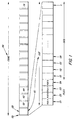
- FIG. 1 is an illustration of an exemplary frame structure in a CDMA system.
- Frame 100 has multiple slots 101, 102, 103, 104, ... , 116.
- Each slot has a pilot portion 120 and a data portion 130.
- the pilot portion 120 has four pilot symbols 121, 122, 123, and 124
- the data portion 130 has multiple data symbols 131, 132, 133, 134, ... , n.
- the pilot symbols 121, 122, 123, and 124 can be used to find different rays.
- the searcher can use a filter that is matched to the pilot symbols (a matched filter) to find the different paths.
- the output of the matched filter is usually referred to as the multipath profile (or the delay profile).
- the delay profile contains more than one spike. The different spikes correspond to the different rays.
- the pilot symbols 121, 122, 123, and 124 can also be used for channel estimation.
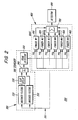
- FIG. 2 is a schematic diagram of the searcher and RAKE receiver portions of a receiver.
- a transmitter (not shown) transmits a signal to receiver 200. Because the signal travels along multiple paths, received signal 201 contains multiple versions of the same signal.
- Searcher 300 uses a matched filter 310 and a peak detector 350 to find and select a set of strongest rays. Searcher 300 can use a second matched filter 320, a slot delay 330, and an accumulator 340 to search more than one slot of frame 100.
- RAKE receiver 400 has six fingers 410, 420, 430, 440, 450, and 460. Each finger is a simple receiver that is configured to receive a different path of the signal 201. For example, finger 410 is configured to receive a path having a time delay of td 1 . Fingers 420, 430, 440, 450, and 460 are configured to receive paths having time delays of td 2 , td 3 , td 4 , td 5 , and td 6 , respectively. The outputs of fingers 410, 420, 430, 440, 450, and 460 are multiplied by individual weights to maximize the received signal-to-noise-and-interference ratio. The weighted outputs are then added by an accumulator 700. The output of accumulator 700 is fed to a detector 800.
- searcher 300 finds a set of rays, but that receiver 200 is a mobile hand-held unit. As receiver 200 moves, these rays are no longer the best rays. If receiver 200 uses weak rays, the signal quality will decrease. The only way that receiver 200 can maintain the same signal quality is to request additional signal power from the base station. Additional signal power increases the amount of interference experienced by the other receivers. The overall interference is minimized when each receiver uses the least amount of signal power possible.
- WO 94/18752 describes a method and apparatus of adaptive maximum likelihood sequence estimation using a variable convergence step size
- EP 0790727 describes a method for demodulating a received signal
- WO 99/29046 describes a method and apparatus for coherently-averaged power estimation.
- a channel estimate generator generates a plurality of channel estimates and a Doppler frequency estimator uses two or more channel estimates to generate a Doppler frequency estimate.
- a Doppler frequency estimator generates a Doppler frequency estimate by calculating the normalized distance between two consecutive channel estimates.
- a receiver uses a Doppler frequency estimate to either (1) adjust the receiver, (2) estimate the velocity of the receiver, (3) determine whether it is necessary to search for new paths, or (4) predict or track new paths.
- the receiver uses a moving average of Doppler frequency estimates to either (1) adjust the receiver, (2) estimate the velocity of the receiver, (3) determine whether it is necessary to search for new paths, or (4) predict or track new paths.
- the receiver uses a weighted combination of Doppler frequency estimates from different paths of a received signal to either (1) adjust the receiver, (2) estimate the velocity of the receiver, (3) determine whether it is necessary to search for new paths, or (4) predict or track new paths.
- An advantage of the invention is that the receiver can estimate the Doppler frequency from the received signal itself. Another advantage is that the need to operate the matched filter is reduced.
- FIG. 1 is an illustration of an exemplary frame structure in a CDMA system.
- FIG. 2 is a schematic diagram of the searcher and RAKE receiver portions of a receiver.
- FIG. 3 is a schematic diagram of a RAKE finger.
- each finger is a simple receiver that is configured to receive a different path of signal 201.
- finger 410 is configured to receive a signal from one of the paths 411.
- Finger 410 can be configured by either shifting the received signal 201 or the despreading code 112.
- despreading code 112 is a long code that spans a large number of symbols. Long code 112 is used to separate, for example, different base stations.
- a short code is a code that spans a single symbol.
- a short code is used to separate, for example, different users in a particular cell.
- integrator 514 uses the short code to obtain individual symbols.
- the individual symbols are divided into pilot symbols 521, 522, 523, and 524 and information symbols 531, 532, 533, ... , n.
- a channel estimate is a measure of the channel's amplitude and phase distortion.
- the receiver has to generate channel estimates for each finger.
- the channel estimate in finger 410 is different from the channel estimate in, for example, finger 420 because finger 410 and finger 420 are configured to receive signals that traveled along different paths.
- the easiest way to generate channel estimate 601 is to compare pilot symbols 521, 522, 523, and 524 with the known pilot symbols 121, 122, 123, and 124.
- combiner 525 can average the product of known pilot 121 with received pilot 521, known pilot 122 with received pilot 522, known pilot 123 with received pilot 523, and known pilot 124 with received pilot 524.
- Channel estimator 527 uses the average from combiner 525 to generate a channel estimate 601.
- FIG. 4 is a graph of the amplitude and phase variation of consecutive channel estimates.
- the channel estimates are from, for example, one of the fingers 410, 420, 430, 440, 450, or 460. Consecutive channel estimates, which are shown as an asterisk, are connected by a line.
- the amplitude and phase variation of, for example, channel estimates 601, 602, 603, and 604 depends on (1) the Rayleigh distribution of the channel and (2) the Doppler frequency of the receiver.
- a Doppler frequency estimator can be configured to use two or more channel estimates to generate a Doppler frequency estimate.
- Doppler frequency estimator 610 uses channel estimates 601 and 602 to generate Doppler frequency estimate 641.
- a normalizer 620 divides channel estimates 601 and 602 by their corresponding lengths to generate normalized channel estimates 621 and 622.
- a subtractor 630 subtracts normalized channel estimate 622 from normalized channel estimate 621 to generate difference 631.
- a multiplier 640 multiplies difference 631 with a constant to generate Doppler frequency estimate 641.
- Doppler frequency estimate 641 can be used to (1) adjust the receiver, (2) estimate the velocity of the receiver, (3) determine whether it is necessary to search for new paths, and/or (4) predict or track new paths.
- Velocity estimator 680 uses Doppler frequency estimate 641 to generate velocity estimate 681.
- Channel estimate 601 may represent a channel estimate from a pilot symbol in slot 101 and channel estimate 602 may represent a channel estimate from slot 101 or slot 102. Or alternatively, channel estimate 601 may represent an average of consecutive channel estimates from slot 101, and channel estimate 602 may represent an average of consecutive channel estimates from slot 102.
- FIG. 6 is a schematic diagram of a Doppler frequency estimator.
- the change in the Doppler frequency can be quite slow. It may be advantageous in some cases to use a moving average of, for example, sixty-four channel estimates.
- a shift register or memory bank can be used to store a plurality of normalized channel estimates. Or alternatively, a shift register or a memory bank can be used to store a plurality of Doppler frequency estimates.
- a combiner 650 can sum and average the resulting channel estimates.
- Doppler frequency estimate 651 can be used to (1) adjust the receiver, (2) estimate the velocity of the receiver, (3) determine whether it is necessary to search for new paths, and/or (4) predict new paths.
- the optimum number of fingers, the weighting of the fingers, and whether to use a moving average in some or all of the fingers depends on, inter alia, the mobile station's environment, the distance between the mobile station and the base station, the speed of the mobile station, and the complexity of the receiver.
Landscapes
- Engineering & Computer Science (AREA)
- Computer Networks & Wireless Communication (AREA)
- Signal Processing (AREA)
- Power Engineering (AREA)
- Mobile Radio Communication Systems (AREA)
- Position Fixing By Use Of Radio Waves (AREA)
- Radar Systems Or Details Thereof (AREA)
Description
- The invention relates to Doppler frequency estimation, and more particularly, to receiving spread spectrum radio signals, such as digitally modulated signals in a Code Division Multiple Access (CDMA) mobile radio telephone system.
- In a CDMA system, different users, base stations, and services are usually separated by unique spreading sequences/codes. The rate of the spreading code (usually referred to as the chip rate) is larger than the information symbol rate. The code rate divided by the information symbol rate is usually referred to as the spreading factor (sf). An information data stream is spread (or coded) by multiplying the information data stream with the spreading code. In a system where there are multiple users, coded signals can be added together to form a composite signal. A receiver can recover any one of the information data streams by correlating the composite signal with the conjugate of the corresponding spreading code.
- In a mobile communications system, signals transmitted between base and mobile stations typically suffer from echo distortion or time dispersion (multipath delay). Multipath delay is caused by, for example, signal reflections from large buildings or nearby mountain ranges. The obstructions cause the signal to proceed to the receiver along not one, but many paths. The receiver receives a composite signal of multiple versions of the transmitted signal that have propagated along different paths (referred to as "rays"). In order to optimally detect the transmitted signal, a device known as a searcher finds the different rays, and another device known as a RAKE receiver "rakes" them together.
-
FIG. 1 is an illustration of an exemplary frame structure in a CDMA system.Frame 100 hasmultiple slots pilot portion 120 and adata portion 130. It will be evident to those skilled in the art that different CDMA systems may have different frame structures. In the example shown, thepilot portion 120 has fourpilot symbols data portion 130 hasmultiple data symbols pilot symbols pilot symbols -
FIG. 2 is a schematic diagram of the searcher and RAKE receiver portions of a receiver. A transmitter (not shown) transmits a signal toreceiver 200. Because the signal travels along multiple paths, receivedsignal 201 contains multiple versions of the same signal.Searcher 300 uses a matchedfilter 310 and apeak detector 350 to find and select a set of strongest rays.Searcher 300 can use a second matchedfilter 320, aslot delay 330, and anaccumulator 340 to search more than one slot offrame 100. - RAKE
receiver 400 has sixfingers signal 201. For example,finger 410 is configured to receive a path having a time delay of td1.Fingers fingers accumulator 700. The output ofaccumulator 700 is fed to adetector 800. - Suppose
searcher 300 finds a set of rays, but thatreceiver 200 is a mobile hand-held unit. Asreceiver 200 moves, these rays are no longer the best rays. Ifreceiver 200 uses weak rays, the signal quality will decrease. The only way thatreceiver 200 can maintain the same signal quality is to request additional signal power from the base station. Additional signal power increases the amount of interference experienced by the other receivers. The overall interference is minimized when each receiver uses the least amount of signal power possible. - Searching for new rays is computationally complex. It is not only time-consuming, it also decreases the battery life of the receiver. The need to search for new paths (and the time delay of the new best paths) is largely dependent on the relative velocity of the receiver. If the receiver can determine the Doppler frequency of the mobile, the receiver can determine whether the mobile has moved and whether searching for new paths is necessary. The receiver can also use the Doppler frequency to track or predict new paths. While researchers have long recognized Doppler frequency as one of the phenomenons affecting the radio channel, these researchers have not developed an effective method for deriving the Doppler frequency from the received signal itself. There is a need for a simple and reliable way to determine the Doppler frequency of a mobile station.
-
WO 94/18752 EP 0790727 describes a method for demodulating a received signal; andWO 99/29046 - According to one aspect of the invention, a channel estimate generator generates a plurality of channel estimates and a Doppler frequency estimator uses two or more channel estimates to generate a Doppler frequency estimate.
- According to another aspect of the invention, a Doppler frequency estimator generates a Doppler frequency estimate by calculating the normalized distance between two consecutive channel estimates.
- According to another aspect of the invention, a receiver uses a Doppler frequency estimate to either (1) adjust the receiver, (2) estimate the velocity of the receiver, (3) determine whether it is necessary to search for new paths, or (4) predict or track new paths.
- According to another aspect of the invention, the receiver uses a moving average of Doppler frequency estimates to either (1) adjust the receiver, (2) estimate the velocity of the receiver, (3) determine whether it is necessary to search for new paths, or (4) predict or track new paths.
- According to another aspect of the invention, the receiver uses a weighted combination of Doppler frequency estimates from different paths of a received signal to either (1) adjust the receiver, (2) estimate the velocity of the receiver, (3) determine whether it is necessary to search for new paths, or (4) predict or track new paths.
- An advantage of the invention is that the receiver can estimate the Doppler frequency from the received signal itself. Another advantage is that the need to operate the matched filter is reduced.
- The foregoing, and other objects, features, and advantages of the invention will be more readily understood upon reading the following detailed description in conjunction with the drawings in which:
-
FIG. 1 is an illustration of an exemplary frame structure in a CDMA system; -
FIG. 2 is a schematic diagram of the searcher and RAKE receiver portions of a receiver; -
FIG. 3 is a schematic diagram of a RAKE finger; -
FIG. 4 is a graph of the amplitude and phase variation of consecutive channel estimates; -
FIG. 5 is a schematic diagram of a Doppler frequency estimator; -
FIG. 6 is a schematic diagram of a Doppler frequency estimator; and -
FIG. 7 is a schematic diagram of a Doppler frequency estimator. - In the following description, specific details such as particular names for circuits, circuit components, and transmission techniques are discussed in order to provide a better understanding of the invention. However, it will be apparent to those skilled in the art that the invention can be practiced in other embodiments that depart from these specific details. In other instances, detailed descriptions of well-known methods and circuits are omitted so as not to obscure the description of the invention with unnecessary detail.
- As discussed above,
FIG. 1 is an illustration of an exemplary frame structure in a CDMA system.FIG. 2 is a schematic diagram of the searcher and RAKE receiver portions of a receiver.FIG. 3 is a schematic diagram of a RAKE finger. As stated above, each finger is a simple receiver that is configured to receive a different path ofsignal 201. For example,finger 410 is configured to receive a signal from one of thepaths 411.Finger 410 can be configured by either shifting the receivedsignal 201 or thedespreading code 112. In some CDMA systems,despreading code 112 is a long code that spans a large number of symbols.Long code 112 is used to separate, for example, different base stations. A short code is a code that spans a single symbol. A short code is used to separate, for example, different users in a particular cell. InFIG. 3 ,integrator 514 uses the short code to obtain individual symbols. The individual symbols are divided into pilot symbols 521, 522, 523, and 524 and information symbols 531, 532, 533, ... , n. - A channel estimate is a measure of the channel's amplitude and phase distortion. In a RAKE receiver, the receiver has to generate channel estimates for each finger. The channel estimate in
finger 410 is different from the channel estimate in, for example,finger 420 becausefinger 410 andfinger 420 are configured to receive signals that traveled along different paths. The easiest way to generatechannel estimate 601 is to compare pilot symbols 521, 522, 523, and 524 with the knownpilot symbols pilots combiner 525 can average the product of knownpilot 121 with received pilot 521, knownpilot 122 with received pilot 522, knownpilot 123 with received pilot 523, and knownpilot 124 with received pilot 524.Channel estimator 527 uses the average fromcombiner 525 to generate achannel estimate 601. - If information symbols 531, 532, 533, ... , n are multiplied by
channel estimate 601 or a filtered version thereof, it is possible to compensate for the channel distortion alongpath 411. The output offinger 410 is multiplied by an individual weight and is combined inaccumulator 700. As discussed in more detail below,channel estimate 601 can also be used to generate a Doppler frequency estimate. -
FIG. 4 is a graph of the amplitude and phase variation of consecutive channel estimates. The channel estimates are from, for example, one of thefingers -
FIG. 5 is a schematic diagram of a Doppler frequency estimator.Doppler frequency estimator 610 estimates the Doppler frequency by estimating the normalized distance between consecutive channel estimates. The normalization is made by dividing the complex channel estimates Ch(k) by the corresponding length.
If the distance D(k) corresponds to the difference between two consecutive normalized complex channel estimates,
the current Doppler frequency, fD(k), is given by the following equation.
It will be evident to those skilled in the art that the speed of the mobile station can be found by solving the following equation,
where λ is equal to the speed of light (3*108 m/s) divided by the carrier frequency of the signal (fc) and θ is the angle between the signal and the direction of travel of the mobile station. - In
FIG. 5 ,Doppler frequency estimator 610 uses channel estimates 601 and 602 to generateDoppler frequency estimate 641. Anormalizer 620 divides channel estimates 601 and 602 by their corresponding lengths to generate normalized channel estimates 621 and 622. Asubtractor 630 subtracts normalizedchannel estimate 622 from normalizedchannel estimate 621 to generatedifference 631. Amultiplier 640 multipliesdifference 631 with a constant to generateDoppler frequency estimate 641.Doppler frequency estimate 641 can be used to (1) adjust the receiver, (2) estimate the velocity of the receiver, (3) determine whether it is necessary to search for new paths, and/or (4) predict or track new paths. Velocity estimator 680 usesDoppler frequency estimate 641 to generate velocity estimate 681. - If, for example, adjacent pilot symbols are used to generate more than one channel estimate, it is not necessary to use these consecutive channel estimates to generate a Doppler frequency. It is possible to average these consecutive channel estimates, and use an average from a subsequent group of adjacent pilot symbols to generate the Doppler frequency estimate.
Channel estimate 601 may represent a channel estimate from a pilot symbol in slot 101 andchannel estimate 602 may represent a channel estimate from slot 101 orslot 102. Or alternatively,channel estimate 601 may represent an average of consecutive channel estimates from slot 101, andchannel estimate 602 may represent an average of consecutive channel estimates fromslot 102. -
FIG. 6 is a schematic diagram of a Doppler frequency estimator. When, for example, the mobile station is being used by a pedestrian, the change in the Doppler frequency can be quite slow. It may be advantageous in some cases to use a moving average of, for example, sixty-four channel estimates. InFIG. 6 , a shift register or memory bank can be used to store a plurality of normalized channel estimates. Or alternatively, a shift register or a memory bank can be used to store a plurality of Doppler frequency estimates. Acombiner 650 can sum and average the resulting channel estimates.Doppler frequency estimate 651 can be used to (1) adjust the receiver, (2) estimate the velocity of the receiver, (3) determine whether it is necessary to search for new paths, and/or (4) predict new paths. -
FIG. 7 is a schematic diagram of a Doppler frequency estimator.Doppler frequency estimator 610 uses channel estimates fromfinger 410 to calculateDoppler frequency estimate 661.Doppler frequency estimators fingers Combiner 670 can generate a weighted combination ofestimates Doppler frequency estimate 671 can be used to (1) adjust the receiver, (2) estimate the velocity of the receiver, (3) determine whether it is necessary to search for new paths, and/or (4) predict new paths. In some cases, it may be advantageous to use only one finger to generate the Doppler frequency estimate. It may be advantageous to use only the strongest finger or one of the fingers other than the strongest finger. In other cases, it may be advantageous to combine some or all of the fingers. The optimum number of fingers, the weighting of the fingers, and whether to use a moving average in some or all of the fingers depends on, inter alia, the mobile station's environment, the distance between the mobile station and the base station, the speed of the mobile station, and the complexity of the receiver. - While the foregoing description makes reference to particular illustrative embodiments, these examples should not be construed as limitations. Not only can the inventive system be modified for other transmission techniques; it can also be modified for other cellular systems. Thus, the present invention is not limited to the disclosed embodiments, but is to be accorded the widest scope consistent with the claims below.
Claims (22)
- An apparatus for receiving a signal, the apparatus comprising:a channel estimate generator (527), the channel estimate generator (527) configured to generate a plurality of channel estimates;characterised in that the apparatus further comprises:a Doppler frequency estimator (610), the Doppler frequency estimator (610) configured to use two or more channel estimates to generate a Doppler frequency estimate, wherein the Doppler frequency estimator (610) comprises a normalizer (620), the normalizer (620) configured to normalize at least two channel estimates.
- An apparatus as described in claim 1, the Doppler frequency estimator (610) further comprising a subtractor (630), the subtractor (630) configured to calculate a difference between said at least two normalized channel estimates.
- An apparatus as described in claim 2, the Doppler frequency estimator (610) further comprising a multiplier (640), the multiplier (640) configured to multiply the difference with a constant.
- An apparatus as described in claim 1, the Doppler frequency estimator (610) comprising a normalizer (620), the normalizer (620) configured to normalize at least two consecutive channel estimates.
- An apparatus as described in claim 4, the Doppler frequency estimator (610) further comprising a subtractor (630), the subtractor (630) configured to calculate a difference between said at least two consecutive normalized channel estimates.
- An apparatus as described in claim 5, the Doppler frequency estimator (610) further comprising a multiplier (640), the multiplier (640) configured to multiply the difference with a constant.
- An apparatus as described in claim 6, wherein Ch(k) and Ch(k-1) are consecutive channel estimates and the Doppler frequency estimate is given by the equation

- An apparatus as described in claim 1, the apparatus further comprising a velocity estimator, the velocity estimator configured to use the Doppler frequency estimate to generate a velocity estimate.
- An apparatus as described in claim 1, the apparatus further comprising a combiner (650), the combiner (650) configured to average a plurality of Doppler frequency estimates.
- An apparatus as described in claim 9, the apparatus further comprising a velocity estimator, the velocity estimator configured to use the average to generate a velocity estimate.
- An apparatus as described in claim 1, the channel estimate generator (527) configured to receive a first group of pilot symbols.
- An apparatus as described in claim 11, the channel estimate generator (527) configured to receive a second group of pilot symbols, the second group of pilot symbols separated from the first group of pilot symbols by a group of information symbols.
- An apparatus as described in claim 12, the Doppler frequency estimator (610) configured to use a channel estimate from the first group of pilot symbols and a channel estimate from the second group of pilot symbols to generate the Doppler frequency estimate.
- An apparatus as described in claim 13, the Doppler frequency estimator (610) configured to use an average of channel estimates from the first group of pilot symbols and an average of channel estimates from the second group of pilot symbols to generate the Doppler frequency estimate.
- An apparatus for receiving a spread spectrum signal, the apparatus comprising:a plurality of fingers (410, 420, 430, 440, 450, 460);a searcher (300), the searcher (300) configured to find a path for each finger; andan apparatus for receiving a signal as claimed in claim 1;wherein the channel estimator (527) is configured to generate a plurality of channel estimates for one of the fingers; and the Doppler frequency estimator (610) is configured to use two or more channel estimates from said one of the fingers to generate the Doppler frequency estimate.
- An apparatus as described in claim 15, wherein the Doppler frequency estimate is used to adjust at least one of the fingers.
- An apparatus as described in claim 15, wherein the searcher (300) uses the Doppler frequency estimate to determine whether to search for new paths.
- An apparatus as described in claim 15, wherein the Doppler frequency estimate is used to predict the occurrence of new paths.
- An apparatus as described in claim 15, wherein channel estimates from the strongest finger are used to generate the Doppler frequency estimate.
- An apparatus as described in claim 15, wherein channel estimates from a finger other than the strongest finger are used to generate the Doppler frequency estimate.
- An apparatus as described in claim 15, the apparatus further comprising a plurality of channel estimators (527) and a plurality of Doppler frequency estimators (610), each Doppler frequency estimator (610) configured to use two or more channel estimates from a different channel estimator (527) to generate a Doppler frequency estimate.
- An apparatus as described in claim 21, the apparatus further comprising a combiner (670), the combiner (670) configured to calculate a weighted combination of Doppler frequency estimates from at least two of the Doppler frequency estimators (610).
Applications Claiming Priority (3)
| Application Number | Priority Date | Filing Date | Title |
|---|---|---|---|
| US09/387,788 US6850505B1 (en) | 1999-09-01 | 1999-09-01 | Method and apparatus for Doppler frequency estimation |
| US387788 | 1999-09-01 | ||
| PCT/EP2000/008369 WO2001017185A1 (en) | 1999-09-01 | 2000-08-28 | Estimation, in a rake receiver, of the rate of change of the channel |
Publications (2)
| Publication Number | Publication Date |
|---|---|
| EP1212871A1 EP1212871A1 (en) | 2002-06-12 |
| EP1212871B1 true EP1212871B1 (en) | 2012-10-31 |
Family
ID=23531377
Family Applications (1)
| Application Number | Title | Priority Date | Filing Date |
|---|---|---|---|
| EP00958506A Expired - Lifetime EP1212871B1 (en) | 1999-09-01 | 2000-08-28 | Estimation, in a rake receiver, of the rate of change of the channel |
Country Status (9)
| Country | Link |
|---|---|
| US (1) | US6850505B1 (en) |
| EP (1) | EP1212871B1 (en) |
| JP (1) | JP4515680B2 (en) |
| CN (1) | CN1158820C (en) |
| AU (1) | AU7000100A (en) |
| ES (1) | ES2395397T3 (en) |
| MY (1) | MY122571A (en) |
| PT (1) | PT1212871E (en) |
| WO (1) | WO2001017185A1 (en) |
Families Citing this family (21)
| Publication number | Priority date | Publication date | Assignee | Title |
|---|---|---|---|---|
| JP3407706B2 (en) | 1999-11-30 | 2003-05-19 | 日本電気株式会社 | CDMA portable telephone apparatus and drive mode setting / cancelling method used therefor |
| US20020176485A1 (en) * | 2001-04-03 | 2002-11-28 | Hudson John E. | Multi-cast communication system and method of estimating channel impulse responses therein |
| KR100405657B1 (en) * | 2001-05-02 | 2003-11-14 | 엘지전자 주식회사 | Method and Apparatus for frequency presumption in wireless communication system |
| CN1156179C (en) * | 2001-09-03 | 2004-06-30 | 信息产业部电信传输研究所 | Dynamic regulation method and device of channel estimation everage region |
| DE60314838T2 (en) * | 2003-04-04 | 2007-10-25 | Mitsubishi Denki K.K. | Method for sending data in a telecommunication system |
| JP4407829B2 (en) * | 2003-05-21 | 2010-02-03 | 日本電気株式会社 | Reception device and wireless communication system using the same |
| WO2005009057A2 (en) * | 2003-07-14 | 2005-01-27 | Interdigital Technology Corporation | High performance wireless receiver with cluster multipath interference suppression circuit |
| KR101009827B1 (en) * | 2003-09-16 | 2011-01-19 | 삼성전자주식회사 | Estimating apparatus and method of mobile station speed in a mobile communication system |
| KR101002857B1 (en) * | 2003-09-16 | 2010-12-21 | 삼성전자주식회사 | Method and apparatus for estimating a velocity of a mobile terminal in a mobile communication system |
| US20060045192A1 (en) * | 2004-08-25 | 2006-03-02 | Hiroshi Hayashi | Method and apparatus for pilot channel transmission and reception within a multi-carrier communication system |
| CN100362903C (en) * | 2005-05-11 | 2008-01-16 | 北京北方烽火科技有限公司 | A method of hard switch between heterogeneous systems for WCDMA system |
| JP2007006105A (en) * | 2005-06-23 | 2007-01-11 | Nec Corp | Radio base station and doppler frequency estimating method |
| KR100630495B1 (en) * | 2005-08-19 | 2006-10-02 | 한양대학교 산학협력단 | Method for wireless fading channel simulation in wirelesss communication system and record media recored program for realizing the same |
| US7647049B2 (en) * | 2006-07-12 | 2010-01-12 | Telefonaktiebolaget L M Ericsson (Publ) | Detection of high velocity movement in a telecommunication system |
| EP1983656A1 (en) | 2007-04-19 | 2008-10-22 | MediaTek Inc. | Shared filter design for pilot symbol averaging in rake fingers in WCDMA systems |
| WO2009079848A1 (en) * | 2007-12-21 | 2009-07-02 | Zte Corporation | Method for estimating frequency spectrum spreading and speed of mobile station |
| JP5320811B2 (en) * | 2008-05-13 | 2013-10-23 | 富士通株式会社 | RAKE receiver, base station apparatus, reception control method, and reception control program |
| CN101667855B (en) * | 2009-09-04 | 2012-10-10 | 凌阳电通科技股份有限公司 | Estimating system and estimating method of Doppler frequency |
| US8644436B2 (en) * | 2012-02-17 | 2014-02-04 | Alcatel Lucent | Method and apparatus for enhanced uplink general rake channel estimation |
| US9584974B1 (en) * | 2016-05-11 | 2017-02-28 | Cognitive Systems Corp. | Detecting motion based on reference signal transmissions |
| DE102020202890B3 (en) * | 2020-03-06 | 2021-07-08 | Continental Automotive Gmbh | Method and communication device for compensating for Doppler effects in received wireless communication signals |
Family Cites Families (14)
| Publication number | Priority date | Publication date | Assignee | Title |
|---|---|---|---|---|
| US4914699A (en) * | 1988-10-11 | 1990-04-03 | Itt Corporation | High frequency anti-jam communication system terminal |
| JPH06502291A (en) * | 1991-06-27 | 1994-03-10 | テレフオンアクチーボラゲツト エル エム エリクソン | Method and apparatus for estimating Doppler frequency of mobile station |
| US5577068A (en) * | 1992-06-08 | 1996-11-19 | Ericsson Ge Mobile Communications Inc. | Generalized direct update viterbi equalizer |
| US5818876A (en) | 1993-02-01 | 1998-10-06 | Motorola, Inc. | Method and apparatus of adaptive maximum likelihood sequence estimation using a variable convergence step size |
| TW351886B (en) * | 1993-09-27 | 1999-02-01 | Ericsson Telefon Ab L M | Using two classes of channels with different capacity |
| US5719899A (en) * | 1994-02-25 | 1998-02-17 | U.S. Philips Corporation | Multiple access digital transmission system and a radio base station and a receiver for use in such a system |
| EP0790727A3 (en) * | 1996-02-19 | 1999-06-23 | Ascom Tech Ag | Method for demodulating a received signal |
| US6067315A (en) * | 1997-12-04 | 2000-05-23 | Telefonaktiebolaget Lm Ericsson | Method and apparatus for coherently-averaged power estimation |
| JP3805520B2 (en) * | 1998-01-28 | 2006-08-02 | 富士通株式会社 | Speed estimation apparatus and method in mobile communication |
| JPH11234190A (en) * | 1998-02-12 | 1999-08-27 | Oki Electric Ind Co Ltd | Maximum doppler frequency observation circuit, radio channel estimation circuit and object moving speed observation circuit |
| US6470000B1 (en) * | 1998-10-14 | 2002-10-22 | Agere Systems Guardian Corp. | Shared correlator system and method for direct-sequence CDMA demodulation |
| US6377813B1 (en) * | 1998-12-03 | 2002-04-23 | Nokia Corporation | Forward link closed loop power control for a third generation wideband CDMA system |
| US6424642B1 (en) * | 1998-12-31 | 2002-07-23 | Texas Instruments Incorporated | Estimation of doppler frequency through autocorrelation of pilot symbols |
| US6542562B1 (en) * | 1999-02-09 | 2003-04-01 | Telefonaktiebolaget Lm Ericsson (Publ) | Approximated MMSE-based channel estimator in a mobile communication system |
-
1999
- 1999-09-01 US US09/387,788 patent/US6850505B1/en not_active Expired - Lifetime
-
2000
- 2000-08-28 EP EP00958506A patent/EP1212871B1/en not_active Expired - Lifetime
- 2000-08-28 WO PCT/EP2000/008369 patent/WO2001017185A1/en active Application Filing
- 2000-08-28 JP JP2001521011A patent/JP4515680B2/en not_active Expired - Fee Related
- 2000-08-28 PT PT958506T patent/PT1212871E/en unknown
- 2000-08-28 AU AU70001/00A patent/AU7000100A/en not_active Abandoned
- 2000-08-28 CN CNB00814852XA patent/CN1158820C/en not_active Expired - Lifetime
- 2000-08-28 ES ES00958506T patent/ES2395397T3/en not_active Expired - Lifetime
- 2000-08-29 MY MYPI20003971A patent/MY122571A/en unknown
Also Published As
| Publication number | Publication date |
|---|---|
| PT1212871E (en) | 2012-12-24 |
| US6850505B1 (en) | 2005-02-01 |
| WO2001017185A8 (en) | 2004-02-19 |
| JP2003508969A (en) | 2003-03-04 |
| WO2001017185A1 (en) | 2001-03-08 |
| ES2395397T3 (en) | 2013-02-12 |
| JP4515680B2 (en) | 2010-08-04 |
| CN1158820C (en) | 2004-07-21 |
| EP1212871A1 (en) | 2002-06-12 |
| MY122571A (en) | 2006-04-29 |
| CN1382335A (en) | 2002-11-27 |
| WO2001017185A9 (en) | 2002-09-06 |
| AU7000100A (en) | 2001-03-26 |
Similar Documents
| Publication | Publication Date | Title |
|---|---|---|
| EP1212871B1 (en) | Estimation, in a rake receiver, of the rate of change of the channel | |
| US6711384B2 (en) | Apparatus and method for controlling communications based on moving speed | |
| EP1323236B1 (en) | Method and apparatus for automatic frequency control in a cdma receiver | |
| CN1192505C (en) | CDMA receiver that shares tracking device among multiple Rake branches | |
| US20030012267A1 (en) | CDMA receiver, and searcher in a CDMA receiver | |
| JP4295112B2 (en) | Construction of interference matrix for coded signal processing engine | |
| EP0808031B1 (en) | Spread spectrum multi-path demodulator | |
| US20070116103A1 (en) | Method and Apparatus for Configuring a RAKE Receiver | |
| CN1622653A (en) | Apparatus and method for frequency estimation of TD-SCDMA system downlink | |
| KR100361408B1 (en) | Synchronous capture circuit for code division multiple access communication | |
| US6650686B1 (en) | Spread spectrum communication system and handover method therein | |
| US6490315B2 (en) | Code synchronization method and receiver | |
| US20020075946A1 (en) | Method and apparatus for searching multipaths of mobile communication system | |
| CN100444531C (en) | Receiving apparatus | |
| US20030114125A1 (en) | Interference suppression in a radio receiver | |
| US7352799B2 (en) | Channel estimation in spread spectrum system | |
| JP3794617B2 (en) | Cell search method for mobile station in CDMA mobile communication system, and CDMA mobile communication system | |
| JP3228311B2 (en) | Receiver | |
| EP1672808A1 (en) | Selecting peak delay values for a RAKE receiver | |
| WO2006066765A1 (en) | Selecting peak delay values for a rake receiver |
Legal Events
| Date | Code | Title | Description |
|---|---|---|---|
| PUAI | Public reference made under article 153(3) epc to a published international application that has entered the european phase |
Free format text: ORIGINAL CODE: 0009012 |
|
| AK | Designated contracting states |
Kind code of ref document: A1 Designated state(s): AT BE CH CY DE DK ES FI FR GB GR IE IT LI LU MC NL PT SE |
|
| AX | Request for extension of the european patent |
Free format text: AL;LT;LV;MK;RO;SI |
|
| 17P | Request for examination filed |
Effective date: 20020327 |
|
| RAP1 | Party data changed (applicant data changed or rights of an application transferred) |
Owner name: TELEFONAKTIEBOLAGET LM ERICSSON (PUBL) |
|
| 17Q | First examination report despatched |
Effective date: 20091120 |
|
| GRAP | Despatch of communication of intention to grant a patent |
Free format text: ORIGINAL CODE: EPIDOSNIGR1 |
|
| GRAS | Grant fee paid |
Free format text: ORIGINAL CODE: EPIDOSNIGR3 |
|
| GRAA | (expected) grant |
Free format text: ORIGINAL CODE: 0009210 |
|
| AK | Designated contracting states |
Kind code of ref document: B1 Designated state(s): AT BE CH CY DE DK ES FI FR GB GR IE IT LI LU MC NL PT SE |
|
| REG | Reference to a national code |
Ref country code: GB Ref legal event code: FG4D Ref country code: CH Ref legal event code: EP |
|
| REG | Reference to a national code |
Ref country code: AT Ref legal event code: REF Ref document number: 582521 Country of ref document: AT Kind code of ref document: T Effective date: 20121115 |
|
| REG | Reference to a national code |
Ref country code: IE Ref legal event code: FG4D |
|
| REG | Reference to a national code |
Ref country code: PT Ref legal event code: SC4A Free format text: AVAILABILITY OF NATIONAL TRANSLATION Effective date: 20121210 |
|
| REG | Reference to a national code |
Ref country code: DE Ref legal event code: R096 Ref document number: 60047608 Country of ref document: DE Effective date: 20121227 |
|
| REG | Reference to a national code |
Ref country code: ES Ref legal event code: FG2A Ref document number: 2395397 Country of ref document: ES Kind code of ref document: T3 Effective date: 20130212 |
|
| REG | Reference to a national code |
Ref country code: NL Ref legal event code: T3 |
|
| REG | Reference to a national code |
Ref country code: AT Ref legal event code: MK05 Ref document number: 582521 Country of ref document: AT Kind code of ref document: T Effective date: 20121031 |
|
| PG25 | Lapsed in a contracting state [announced via postgrant information from national office to epo] |
Ref country code: FI Free format text: LAPSE BECAUSE OF FAILURE TO SUBMIT A TRANSLATION OF THE DESCRIPTION OR TO PAY THE FEE WITHIN THE PRESCRIBED TIME-LIMIT Effective date: 20121031 Ref country code: SE Free format text: LAPSE BECAUSE OF FAILURE TO SUBMIT A TRANSLATION OF THE DESCRIPTION OR TO PAY THE FEE WITHIN THE PRESCRIBED TIME-LIMIT Effective date: 20121031 |
|
| PG25 | Lapsed in a contracting state [announced via postgrant information from national office to epo] |
Ref country code: CY Free format text: LAPSE BECAUSE OF FAILURE TO SUBMIT A TRANSLATION OF THE DESCRIPTION OR TO PAY THE FEE WITHIN THE PRESCRIBED TIME-LIMIT Effective date: 20121031 Ref country code: GR Free format text: LAPSE BECAUSE OF FAILURE TO SUBMIT A TRANSLATION OF THE DESCRIPTION OR TO PAY THE FEE WITHIN THE PRESCRIBED TIME-LIMIT Effective date: 20130201 Ref country code: BE Free format text: LAPSE BECAUSE OF FAILURE TO SUBMIT A TRANSLATION OF THE DESCRIPTION OR TO PAY THE FEE WITHIN THE PRESCRIBED TIME-LIMIT Effective date: 20121031 |
|
| PG25 | Lapsed in a contracting state [announced via postgrant information from national office to epo] |
Ref country code: AT Free format text: LAPSE BECAUSE OF FAILURE TO SUBMIT A TRANSLATION OF THE DESCRIPTION OR TO PAY THE FEE WITHIN THE PRESCRIBED TIME-LIMIT Effective date: 20121031 |
|
| PG25 | Lapsed in a contracting state [announced via postgrant information from national office to epo] |
Ref country code: DK Free format text: LAPSE BECAUSE OF FAILURE TO SUBMIT A TRANSLATION OF THE DESCRIPTION OR TO PAY THE FEE WITHIN THE PRESCRIBED TIME-LIMIT Effective date: 20121031 |
|
| PG25 | Lapsed in a contracting state [announced via postgrant information from national office to epo] |
Ref country code: IT Free format text: LAPSE BECAUSE OF FAILURE TO SUBMIT A TRANSLATION OF THE DESCRIPTION OR TO PAY THE FEE WITHIN THE PRESCRIBED TIME-LIMIT Effective date: 20121031 |
|
| PLBE | No opposition filed within time limit |
Free format text: ORIGINAL CODE: 0009261 |
|
| STAA | Information on the status of an ep patent application or granted ep patent |
Free format text: STATUS: NO OPPOSITION FILED WITHIN TIME LIMIT |
|
| 26N | No opposition filed |
Effective date: 20130801 |
|
| REG | Reference to a national code |
Ref country code: DE Ref legal event code: R097 Ref document number: 60047608 Country of ref document: DE Effective date: 20130801 |
|
| REG | Reference to a national code |
Ref country code: CH Ref legal event code: PL |
|
| PG25 | Lapsed in a contracting state [announced via postgrant information from national office to epo] |
Ref country code: CH Free format text: LAPSE BECAUSE OF NON-PAYMENT OF DUE FEES Effective date: 20130831 Ref country code: LI Free format text: LAPSE BECAUSE OF NON-PAYMENT OF DUE FEES Effective date: 20130831 Ref country code: MC Free format text: LAPSE BECAUSE OF FAILURE TO SUBMIT A TRANSLATION OF THE DESCRIPTION OR TO PAY THE FEE WITHIN THE PRESCRIBED TIME-LIMIT Effective date: 20121031 |
|
| REG | Reference to a national code |
Ref country code: IE Ref legal event code: MM4A |
|
| REG | Reference to a national code |
Ref country code: FR Ref legal event code: ST Effective date: 20140430 |
|
| PG25 | Lapsed in a contracting state [announced via postgrant information from national office to epo] |
Ref country code: IE Free format text: LAPSE BECAUSE OF NON-PAYMENT OF DUE FEES Effective date: 20130828 |
|
| PG25 | Lapsed in a contracting state [announced via postgrant information from national office to epo] |
Ref country code: FR Free format text: LAPSE BECAUSE OF NON-PAYMENT OF DUE FEES Effective date: 20130902 |
|
| PG25 | Lapsed in a contracting state [announced via postgrant information from national office to epo] |
Ref country code: LU Free format text: LAPSE BECAUSE OF NON-PAYMENT OF DUE FEES Effective date: 20130828 |
|
| PGFP | Annual fee paid to national office [announced via postgrant information from national office to epo] |
Ref country code: NL Payment date: 20190826 Year of fee payment: 20 |
|
| PGFP | Annual fee paid to national office [announced via postgrant information from national office to epo] |
Ref country code: ES Payment date: 20190902 Year of fee payment: 20 Ref country code: PT Payment date: 20190801 Year of fee payment: 20 Ref country code: DE Payment date: 20190828 Year of fee payment: 20 |
|
| PGFP | Annual fee paid to national office [announced via postgrant information from national office to epo] |
Ref country code: GB Payment date: 20190827 Year of fee payment: 20 |
|
| REG | Reference to a national code |
Ref country code: DE Ref legal event code: R071 Ref document number: 60047608 Country of ref document: DE |
|
| REG | Reference to a national code |
Ref country code: NL Ref legal event code: MK Effective date: 20200827 |
|
| REG | Reference to a national code |
Ref country code: GB Ref legal event code: PE20 Expiry date: 20200827 |
|
| PG25 | Lapsed in a contracting state [announced via postgrant information from national office to epo] |
Ref country code: GB Free format text: LAPSE BECAUSE OF EXPIRATION OF PROTECTION Effective date: 20200827 Ref country code: PT Free format text: LAPSE BECAUSE OF EXPIRATION OF PROTECTION Effective date: 20200907 |
|
| REG | Reference to a national code |
Ref country code: ES Ref legal event code: FD2A Effective date: 20220128 |
|
| PG25 | Lapsed in a contracting state [announced via postgrant information from national office to epo] |
Ref country code: ES Free format text: LAPSE BECAUSE OF EXPIRATION OF PROTECTION Effective date: 20200829 |