EP1209613B1 - Compact bar code scanning arrangement - Google Patents

Compact bar code scanning arrangement Download PDF

Info

Publication number
EP1209613B1
EP1209613B1 EP02002293A EP02002293A EP1209613B1 EP 1209613 B1 EP1209613 B1 EP 1209613B1 EP 02002293 A EP02002293 A EP 02002293A EP 02002293 A EP02002293 A EP 02002293A EP 1209613 B1 EP1209613 B1 EP 1209613B1
Authority
EP
European Patent Office
Prior art keywords
scanning
bar code
permanent magnet
flexural member
mirror
Prior art date
Legal status (The legal status is an assumption and is not a legal conclusion. Google has not performed a legal analysis and makes no representation as to the accuracy of the status listed.)
Expired - Lifetime
Application number
EP02002293A
Other languages
German (de)
French (fr)
Other versions
EP1209613A1 (en
Inventor
Simon Bard
Boris Metlitsky
Mark Krichever
Jerome Symbol Technologies INC. Swartz
Askold c/o Symbol Technologies INC. Stratienco
Joseph Katz
Current Assignee (The listed assignees may be inaccurate. Google has not performed a legal analysis and makes no representation or warranty as to the accuracy of the list.)
Symbol Technologies LLC
Original Assignee
Symbol Technologies LLC
Priority date (The priority date is an assumption and is not a legal conclusion. Google has not performed a legal analysis and makes no representation as to the accuracy of the date listed.)
Filing date
Publication date
Application filed by Symbol Technologies LLC filed Critical Symbol Technologies LLC
Priority to EP03011022A priority Critical patent/EP1345158A3/en
Publication of EP1209613A1 publication Critical patent/EP1209613A1/en
Application granted granted Critical
Publication of EP1209613B1 publication Critical patent/EP1209613B1/en
Anticipated expiration legal-status Critical
Expired - Lifetime legal-status Critical Current

Links

Images

Classifications

    • GPHYSICS
    • G06COMPUTING; CALCULATING OR COUNTING
    • G06KGRAPHICAL DATA READING; PRESENTATION OF DATA; RECORD CARRIERS; HANDLING RECORD CARRIERS
    • G06K7/00Methods or arrangements for sensing record carriers, e.g. for reading patterns
    • G06K7/10Methods or arrangements for sensing record carriers, e.g. for reading patterns by electromagnetic radiation, e.g. optical sensing; by corpuscular radiation
    • G06K7/10544Methods or arrangements for sensing record carriers, e.g. for reading patterns by electromagnetic radiation, e.g. optical sensing; by corpuscular radiation by scanning of the records by radiation in the optical part of the electromagnetic spectrum
    • G06K7/10821Methods or arrangements for sensing record carriers, e.g. for reading patterns by electromagnetic radiation, e.g. optical sensing; by corpuscular radiation by scanning of the records by radiation in the optical part of the electromagnetic spectrum further details of bar or optical code scanning devices
    • G06K7/1098Methods or arrangements for sensing record carriers, e.g. for reading patterns by electromagnetic radiation, e.g. optical sensing; by corpuscular radiation by scanning of the records by radiation in the optical part of the electromagnetic spectrum further details of bar or optical code scanning devices the scanning arrangement having a modular construction
    • GPHYSICS
    • G06COMPUTING; CALCULATING OR COUNTING
    • G06FELECTRIC DIGITAL DATA PROCESSING
    • G06F1/00Details not covered by groups G06F3/00 - G06F13/00 and G06F21/00
    • G06F1/16Constructional details or arrangements
    • G06F1/1613Constructional details or arrangements for portable computers
    • G06F1/163Wearable computers, e.g. on a belt
    • GPHYSICS
    • G06COMPUTING; CALCULATING OR COUNTING
    • G06FELECTRIC DIGITAL DATA PROCESSING
    • G06F3/00Input arrangements for transferring data to be processed into a form capable of being handled by the computer; Output arrangements for transferring data from processing unit to output unit, e.g. interface arrangements
    • G06F3/01Input arrangements or combined input and output arrangements for interaction between user and computer
    • G06F3/03Arrangements for converting the position or the displacement of a member into a coded form
    • G06F3/033Pointing devices displaced or positioned by the user, e.g. mice, trackballs, pens or joysticks; Accessories therefor
    • G06F3/0346Pointing devices displaced or positioned by the user, e.g. mice, trackballs, pens or joysticks; Accessories therefor with detection of the device orientation or free movement in a 3D space, e.g. 3D mice, 6-DOF [six degrees of freedom] pointers using gyroscopes, accelerometers or tilt-sensors
    • GPHYSICS
    • G06COMPUTING; CALCULATING OR COUNTING
    • G06KGRAPHICAL DATA READING; PRESENTATION OF DATA; RECORD CARRIERS; HANDLING RECORD CARRIERS
    • G06K7/00Methods or arrangements for sensing record carriers, e.g. for reading patterns
    • G06K7/10Methods or arrangements for sensing record carriers, e.g. for reading patterns by electromagnetic radiation, e.g. optical sensing; by corpuscular radiation
    • G06K7/10544Methods or arrangements for sensing record carriers, e.g. for reading patterns by electromagnetic radiation, e.g. optical sensing; by corpuscular radiation by scanning of the records by radiation in the optical part of the electromagnetic spectrum
    • G06K7/10554Moving beam scanning
    • G06K7/10564Light sources
    • G06K7/10584Source control
    • GPHYSICS
    • G06COMPUTING; CALCULATING OR COUNTING
    • G06KGRAPHICAL DATA READING; PRESENTATION OF DATA; RECORD CARRIERS; HANDLING RECORD CARRIERS
    • G06K7/00Methods or arrangements for sensing record carriers, e.g. for reading patterns
    • G06K7/10Methods or arrangements for sensing record carriers, e.g. for reading patterns by electromagnetic radiation, e.g. optical sensing; by corpuscular radiation
    • G06K7/10544Methods or arrangements for sensing record carriers, e.g. for reading patterns by electromagnetic radiation, e.g. optical sensing; by corpuscular radiation by scanning of the records by radiation in the optical part of the electromagnetic spectrum
    • G06K7/10554Moving beam scanning
    • G06K7/10594Beam path
    • G06K7/10603Basic scanning using moving elements
    • G06K7/10633Basic scanning using moving elements by oscillation
    • G06K7/10643Activating means
    • G06K7/10653Activating means using flexible or piezoelectric means
    • GPHYSICS
    • G06COMPUTING; CALCULATING OR COUNTING
    • G06KGRAPHICAL DATA READING; PRESENTATION OF DATA; RECORD CARRIERS; HANDLING RECORD CARRIERS
    • G06K7/00Methods or arrangements for sensing record carriers, e.g. for reading patterns
    • G06K7/10Methods or arrangements for sensing record carriers, e.g. for reading patterns by electromagnetic radiation, e.g. optical sensing; by corpuscular radiation
    • G06K7/10544Methods or arrangements for sensing record carriers, e.g. for reading patterns by electromagnetic radiation, e.g. optical sensing; by corpuscular radiation by scanning of the records by radiation in the optical part of the electromagnetic spectrum
    • G06K7/10821Methods or arrangements for sensing record carriers, e.g. for reading patterns by electromagnetic radiation, e.g. optical sensing; by corpuscular radiation by scanning of the records by radiation in the optical part of the electromagnetic spectrum further details of bar or optical code scanning devices
    • G06K7/10881Methods or arrangements for sensing record carriers, e.g. for reading patterns by electromagnetic radiation, e.g. optical sensing; by corpuscular radiation by scanning of the records by radiation in the optical part of the electromagnetic spectrum further details of bar or optical code scanning devices constructional details of hand-held scanners
    • G06K7/10891Methods or arrangements for sensing record carriers, e.g. for reading patterns by electromagnetic radiation, e.g. optical sensing; by corpuscular radiation by scanning of the records by radiation in the optical part of the electromagnetic spectrum further details of bar or optical code scanning devices constructional details of hand-held scanners the scanner to be worn on a finger or on a wrist
    • GPHYSICS
    • G06COMPUTING; CALCULATING OR COUNTING
    • G06FELECTRIC DIGITAL DATA PROCESSING
    • G06F2203/00Indexing scheme relating to G06F3/00 - G06F3/048
    • G06F2203/033Indexing scheme relating to G06F3/033
    • G06F2203/0331Finger worn pointing device
    • GPHYSICS
    • G06COMPUTING; CALCULATING OR COUNTING
    • G06KGRAPHICAL DATA READING; PRESENTATION OF DATA; RECORD CARRIERS; HANDLING RECORD CARRIERS
    • G06K2207/00Other aspects
    • G06K2207/1016Motor control or optical moving unit control

Landscapes

  • Engineering & Computer Science (AREA)
  • Physics & Mathematics (AREA)
  • Electromagnetism (AREA)
  • Theoretical Computer Science (AREA)
  • General Physics & Mathematics (AREA)
  • General Health & Medical Sciences (AREA)
  • Artificial Intelligence (AREA)
  • Computer Vision & Pattern Recognition (AREA)
  • Toxicology (AREA)
  • Health & Medical Sciences (AREA)
  • General Engineering & Computer Science (AREA)
  • Computer Hardware Design (AREA)
  • Human Computer Interaction (AREA)
  • Mechanical Optical Scanning Systems (AREA)
  • Facsimile Scanning Arrangements (AREA)

Description

BACKGROUND OF THE INVENTION 1. Field of the Invention
The present invention relates generally to a compact bar code scanning element which is simple, and does not utilize a relatively bulky motor-driven construction.
In general, it would be desirable to provide a compact bar code scanner which eliminates the need for bulky motor-driven constructions and is capable of achieving a high speed 250-300 Hz scan motion.
The present invention provides in an embodiment a compact bar code scanner which is capable of scanning along a single axis.
2. Discussion of the Prior Art
Various optical readers and optical scanning systems have been developed heretofore for reading bar code symbols appearing on a label or on the surface of an article. The bar code symbol itself is a coded pattern of indicia comprised of a series of bars of various widths spaced apart from one another to bound spaces of various widths, with the bars and spaces having different light-reflecting characteristics.
The scanning of bar code patterns has become more complex as bar code patterns have become both more complex and more compact. A typical bar code pattern includes lines and spaces of different widths extending in an x direction, and can be scanned by one or more linear scans in the x direction. Moreover, because the direction of the scan is not always precisely aligned with the direction of the bar code pattern, more complex omnidirectional scanning patterns are sometimes used, wherein consecutive scan lines are angularly displaced relative to one another to form a complex omnidirectional scanning pattern. Two dimensional (2D) bar code patterns (Code 49) have also been introduced wherein, in addition to a typical bar code pattern having lines and spaces of varying widths along an x direction, typical bar code patterns are stacked one upon the other in the y direction to form the 2D bar code pattern.
Accordingly, scanning of a 2D bar code pattern is more complex, and requires a raster type of scan wherein consecutive x direction scans are displaced in the y direction by the spacing between stacked rows of the 2D bar code pattern to form a raster scan.
Bar code reading type data input systems improve the efficiency and accuracy of data input for a wide variety of applications. The ease of data input in such systems facilitates more frequent and detailed data input, for example to provide efficient inventories, tracking of work in progress, etc. To achieve these advantages, however, users or employees must be willing to consistently use the bar code readers. The readers therefore must be easy and convenient to operate.
A variety of scanning devices are known. One particularly advantageous type of reader is an optical scanner which scans a beam of light, such as a laser beam, across the symbols. Typically, a light source such as a laser generates a light beam which is optically modified to form a beam spot of a certain size at the working distance and is directed by optical components along a light path toward a bar code symbol located in the vicinity of the working distance for reflection from the symbol. The scanner includes a detector which senses the light reflected from the symbol and provides an analog scan signal representing the encoded information. A photodetector having a field of view extending across and slightly past the symbol detects light of variable intensity reflected off the symbol and generates electrical signals indicative of the detected light. A scanning component is situated in the light path. The scanning component may either sweep the beam spot across the symbol and trace a scan line across and past the symbol, or scan the field of view of the photodetector, or do both.
A digitizer, associated with or included in the scanner, processes the analog signal to produce a pulse signal where the widths and spacings between the pulses correspond to the widths of the bars and the spacings between the bars. The digitizer serves as an edge detector or wave shaper circuit, and the threshold value set by the digitizer determines what points of the analog signal represent bar edges. The pulse signal from the digitizer is applied to a decoder. The decoder first determines the pulse widths and spacings of the signal from the digitizer. The decoder then analyzes the widths and spacings to find and decode a legitimate bar code message. This includes analysis to recognize legitimate characters and sequences, as defined by the appropriate code standard. This may also include an initial recognition of the particular standard the scanned symbol conforms to. This recognition of the standard is typically referred to as autodiscrimination.
Often the particular application for the bar code reader requires that the optical scanner be constructed in the form of a hand-held unit, typically in the form of a pistol. The user points the scanner at the object and operates a trigger to activate the scanning of the bar code. In these hand-held units, a light source, such as a visible laser diode (hereinafter VLD) emits a beam of light. To scan the beam across an image, the beam is reflected from a mirror and the mirror is moved in an oscillatory fashion. The oscillation of the mirror causes the reflected beam to scan back and forth in a desired pattern. For example, U.S. Patent No. 4,251,798 discloses a rotating polygon having a planar mirror at each side, each mirror tracing a scan line across the symbol. U.S. Patent Nos. 4,387,297 and 4,409,470 both employ a planar mirror which is repetitively and reciprocally driven in alternate circumferential directions about a drive shaft on which the mirror is mounted. U.S. Patent No. 4,816,660 discloses a multi-mirror construction composed of a generally concave mirror portion and a generally planar mirror portion. The multi-mirror construction is repetitively reciprocally driven in alternate circumferential directions about a drive shaft on which the multi-mirror construction is mounted.
In optical scanners of the type discussed above, the mirror and means to oscillate the mirror add size and weight to the hand-held scanner. In applications involving protracted use, a large heavy hand-held unit can produce fatigue. Also, a user must pick up and aim the scanner at the object, and this operation may be time consuming, cumbersome and inconvenient. In particular, holding, aiming and activating the scanner ties up one of the user's hands completely so that the user cannot concurrently perform other duties. When use of the scanner produces fatigue or is in some way inconvenient, the user is reluctant to operate the scanner, which defeats the data gathering purposes for which bar code systems are intended.
In non-laser scanning systems of the type exemplified by U.S. Patent No. 4,578,571, a non-laser light emitting diode, an optical assembly, a photodetector, and electronic preamplifier/filter circuitry are all fixedly mounted on a common support that is connected to a cantilevered bimorph which is reciprocally driven to jointly move all the aforementioned components back and forth over a bar code symbol to be scanned. The large volume and heavy mass of all the commonly mounted non-laser system components require the expenditure of a great deal of power for the driver. This is not altogether practical in those cases, e.g. battery-powered operation, where power consumption is to be held to a minimum. Also, moving only one or more non-mirrored system components relative to another for conserving power was heretofore not considered desirable, because of optical alignment problems.
The components for the light scanning system, including the light source, optics, photodetector, scanning component and an electrical conductor, are mounted together in a common assembly to constitute a compact, lightweight, scan module. The scan module is mounted in an interchangeable, modular manner in housings of different configurations. For example, the housing can be hand-held and shaped as a cylinder in a so-called flashlight-type configuration, or shaped as a box, or shaped with a gun-like configuration. The housing can be mounted on the back of an operator's arm (see, for example, U.S. Patent 4,766,299) or on one or more fingers of the operator's hand, typically with the aid of a strap, a clip, or a glove. The housing can be mounted on a countertop workstation. The housing can be mounted in a mobile cart, or shopping cart, or in some cases, even in a stationary installation.
US-A-5 144 120 discloses a mirrorless optical scanner, and US-A-5 191 197 discloses incorporation of such a scanner in a modular scanner component system facilitating use of the scanner in a variety of different housing configurations.
GB-A-2 175 705 discloses a dirigible reflector made from a single crystal material such as silicon. The crystal material is selectively etched to form a central mirror surface having an extremely low mass which is freely pivoted at thin portions to a frame member. A drive element block has drives for pivoting the central mirror surface. The drives may be electrostatic or electromagnetic.
US-A-4 421 381 discloses a mechanical vibrating element made from a single insulating substrate such as silicon. The element comprises a frame and a central moving portion connected to the frame via spring portions. A coil pattern is provided on both sides of the central moving portion. When a current is passed through the coil pattern and an external magnetic field is applied, the central moving portion pivots above the spring portions.
EP-A-0 452 844 discloses a bar code scanner which uses an electromagnetic drive. A mirror is mounted on a spring member and a permanent magnet is provided for interacting with the drive coil. The spring member is not mounted across the driving coil.
SUMMARY OF THE INVENTION
The present invention provides a compact bar code scanning element as set forth in claim 1. Preferred embodiments of the present invention may be gathered from the dependent claims.
The compact bar code scanning element is simple, capable of achieving high scanning rates, and does not utilize a relatively bulky motor-driven construction.
BRIEF DESCRIPTION OF THE DRAWINGS
The foregoing objects and advantages of the present invention for a compact bar code scanning element may be more readily understood by one skilled in the art with reference being had to the following detailed description of a preferred embodiment thereof, taken in conjunction with the accompanying drawings wherein like elements are designated by identical reference numerals throughout the several views, and in which:
  • Figure 1 is a perspective view of a simple and compact linear scanning arrangement which is not in accordance with the present invention which is driven without a traditional bulky motor;
  • Figure 2 illustrates a universal pattern scanning arrangement which is not in accordance with the present invention and which operates partially according to the principle of operation of the scanner of Figure 1, and which is capable of scanning at a relatively high frequency in an x direction, and of either not being driven in y scanning to generate a linear x scanning pattern, or of scanning at two different frequencies in a y direction, a relatively high frequency for omnidirectional'scanning patterns, or a relatively low frequency for raster scanning patterns;
  • Figure 3 illustrates a third arrangement which is not in accordance with the present invention and which is somewhat similar in operation to the arrangement of Figure 2, but wherein y and x scanning mechanisms are mounted in a unitary assembly on a common base, and a single scan mirror performs both x and y scanning operations;
  • Figures 4, 5 and 6 illustrate three related arrangements which are not in accordance with the present invention and which are capable of producing virtually any different type of scanning pattern, including linear, omnidirectional such as Lissajous, or raster scanning patterns, and which utilize a single scanning mirror mounted at the free end of an electromagnetically driven central rod, which is capable of oscillating in two orthogonal x and y directions;
  • Figures 7 and 8 illustrate two related universal scanning arrangements which are not in accordance with the present invention and which include a base which mounts in cantilever fashion a low frequency y flexural member which mounts at its free end in cantilever fashion a high frequency flexural member, and wherein an x drive coil is driven with a constant high frequency drive signal to produce x scan deflections, and a second y drive coil uses a drive signal which is one of two fixed frequencies, a low frequency drive signal for raster scanning patterns, or a high frequency drive signal for omnidirectional scanning patterns;
  • Figure 9 illustrates a preferred arrangement of a universal compact bar code scanning arrangement (not in accordance with the present invention) in which a base includes a low frequency y flexural mounting for a mass which provides a low frequency y scanning motion, and a second flexural member is cantilever mounted on the mass and mounts at its surface a scanning mirror and a permanent magnet which interacts with an adjacent encircling x driving coil to produce high frequency x scanning movements and with an adjacent y driving coil to produce either no, or high or low frequency y scanning movements;
  • Figure 10 illustrates the mode of operation of the x driving mechanism in the arrangements of Figures 7, 8 and 9, in which a permanent magnet interacts with an adjacent x driving coil;
  • Figure 11 illustrates the orientation of the permanent magnet of the arrangements of Figure 9 relative to the y driving coil, and illustrates the manner in which the permanent magnet interacts with the y driving coil;
  • Figure 12 illustrates an arrangement wherein a miniature scanner as disclosed herein for a bar code reader is mounted within a housing supported on an index ring mounting on the index finger of an operator, and the electronics in the bar code reader communicates by a short range radio transmitter with a receiver which might typically be mounted on the belt of the operator;
  • Figure 13 illustrates an arrangement similar to Figure 12 wherein a miniature scanner as disclosed herein for a bar code reader is mounted within a housing supported on an index ring mounting on the index finger of an operator, and the electronics in the bar code reader communicates by a wire with a portable terminal mounted on a wrist band on the wrist of the operator;
  • Figures 14 and 15 illustrate respectively a front perspective view and a side elevational view of an embodiment of a torsional mode, miniature scanning element pursuant to the present invention;
  • DETAILED DESCRIPTION OF THE DRAWINGS
    Figure 1 illustrates a simple and compact, high speed, linear bar code scanner which is driven without a traditional bulky motor. Referring to Figure 1, a linear scanning arrangement 10 is provided in which a flexural strip 12 of a suitable flexible material such as Mylar is cantilever mounted to a base 14, as by being secured between two halves of the base 14. The flexural strip 12 supports thereon a miniature permanent magnet 16 positioned inside a coil 18, with an axis passing centrally through the North and South poles of the permanent intersecting the surface of the flexural strip 12 substantially perpendicular thereto. The coil 18 is also secured to the base 14, and a scan mirror 20 is attached to the free end of the cantilever mounted flexural strip 12. By changing the dimensions (length, width and thickness) or the flexural characteristics of the cantilever mounted strip 12, or the mass of the flexural strip 12, the permanent magnet 16 and mirror 20, or the distribution of mass on the flexural strip 12, different resonant frequencies can be established for the vibrating assembly. In general, the natural resonant frequency is determined by the size (length, width and thickness) and flexural strength of the cantilever mounted member, the distribution of mass, and the total mass of the vibrating assembly. Formulas are available and are known in the art to determine the resonant frequency of the vibrating assembly, which can also be tested and developed empirically. When a periodic drive signal 22, such as a sinusoidal signal, is introduced into the coil 18, the periodically reversing magnetic field induced thereby causes the cantilever mounted assembly to oscillate up and down, as shown in Figure 1. This produces a linear scanning motion of the scan mirror 20, which causes a linear scanning of a beam directed onto the mirror by a suitable beam source such as a visible laser diode (VLD) 24. A sinusoidal periodic drive signal causes a periodically reversing magnetic field to be generated by the coil 18, thus creating moments of forces acting upon the North (N) and South (S) poles of the permanent magnet 18, to cause the magnet and the flexible strip 12 on which it is mounted, along with the scan mirror 20 (all of which comprise a cantilever mounted assembly) to vibrate up and down, perpendicular to the flat surface of the flexible strip 12, at a frequency dependent upon the frequency of the periodic drive signal.
    In general, and for all of the arrangements disclosed herein, it is desirable to drive a cantilever mounted assembly or a torsional mode mounted assembly with a periodic signal at or near the resonant frequency of the assembly, and to design the assembly with a natural resonant frequency as high as possible to achieve high scan rates of up to several hundred hertz (e.g. 500 Hz). However, lower scan rates are also possible. In general, the chosen scan rate depends upon the particular application, and a 36 scans per second scan rate is typical, which is generated by a periodic signal of 18 Hz.
    It is noted that in the description herein, the descriptions of further arrangements often build upon the descriptions of earlier arrangements, and accordingly the descriptions of the details, construction and mode of operation, to the extent they are identical or similar, is generally not repeated for the additional arrangements.
    Figure 2 illustrates a universal pattern, compact bar code scanning arrangement which operates partially according to the principle of operation of the scanner of Figure 1, and which is capable of scanning at a relatively high frequency in an x direction, and of not scanning in a y direction for production of a linear x scan, or of scanning at two different resonant frequencies in a y direction, a relatively high frequency or a relatively low frequency. A variety of bar codes and different bar code reading conditions require different types of scan patterns, such as linear scans, raster scan patterns, or omnidirectional scan patterns such as Lissajous type scan patterns. The arrangement of Figure 2 is capable of producing all of these scan patterns with a relatively simple construction, and includes a double resonant construction for producing either a high or low frequency y vertical scan motion.
    In the universal scanning arrangement of Figure 2, a light beam from a suitable source such as a Visible Laser Diode (VLD) 26 is directed initially onto a high speed horizontal x deflection arrangement 28 which produces high speed x scanning deflections of the beam. The x deflection arrangement 28 can be and preferably is the same as the linear scanning arrangement 10 in Figure 1. The resultant x scanned beam is then directed to a vertical deflection arrangement 30, which produces either no, or low or high speed vertical scanning deflections of the beam, provided respectively for raster and omnidirectional scan patterns. The y scanning arrangement 30 includes a flexible base provided with two degrees of mechanical freedom to provide two resonant conditions, a low frequency y scan for raster patterns, and a high frequency y scan for omnidirectional patterns. The y scanning arrangement is driven by the electromagnetic forces produced by a coil 44 which encircles a permanent magnet 42 mounted in the y scanning assembly 30 in a manner similar to that as explained with reference to the arrangement of Figure 1.
    The y scanning assembly 30 comprises a base 34 which supports a cantilever mounted low frequency flexural strip 36 which supports at its free end a mass 38, which in turn supports a smaller cantilever mounted high frequency flexural strip 40. The flexural strip 40 mounts thereon the permanent magnet 42 positioned within the coil 44, and a scanning mirror 46 mounted at the free end of the flexural strip 40. In this arrangement, the mass 38 and all of the structure mounted thereon (40, 42, 46) can oscillate on the cantilever mounted low frequency flexible strip 36 at a low resonant frequency frL, and the magnet 42 and scan mirror 46 can oscillate on the smaller cantilever mounted high frequency flexible strip 40 at a high resonant frequency frh. The mass 38 is selected to tune the resonant frequency of the low frequency y flexural member to be at or near the low frequency y drive signal for efficient operation. Similar to the first arrangement, for efficient operation the resonant mechanical frequency of the high frequency y flexural member with the y scanning mirror and permanent magnet mounted thereon is designed to be at or near the frequency of the periodically changing high frequency y drive signal. The resonant frequency of each vibrating assembly is determined in general by the spring constant K of the vibrating member and the mass M and distribution of mass of the vibrating assembly. In the two degree of freedom arrangement of Figure 2, each of the two vibrating assemblies has a different spring constant K (K1 and K2) and a different mass M (M1 and M2) and distribution of mass.
    Selection of either the low resonant frequency frL or the high resonant frequency frh is accomplished by changing the frequency of the y periodic drive signal 48 through the y driving coil 44. When there is no driving current through the y driving coil 44, a laser beam from the VLD 26 is incident on the mirror 20 of the scanning assembly 28 which produces a fast (about 300 Hz) x scan line, which is directed onto and reflected by the mirror 46 of the y scanning assembly 30 without any changes in the scan pattern, thereby producing a linear horizontal scan line. When a low frequency signal 48 is connected to the y driving coil 44, it produces a low frequency vertical motion about the low frequency flexible strip 36, thereby producing a raster pattern. When a high frequency signal 48 is connected to the y driving coil 40, it produces a high frequency vertical motion about the high frequency strip 40, thereby producing an omnidirectional scanning pattern. In the second arrangement, the scanning movement in the y direction can be designed to be a desired ratio to the scanning movement in the x direction in accordance with the desired omnidirectional scan pattern.
    Figure 3 illustrates a third arrangement (not in accordance with the present invention) which is somewhat similar in operation to the arrangement of Figure 2, but wherein y and x scanning mechanisms 56, 58 are mounted in a unitary assembly on a common base 60, which in a compact or miniaturized scanner can comprise a PC board. For perspective, in one designed embodiment the length of the base 60 was 1.1 inches, the height was 0.45 inches, and the width was 0.45 inches. The y scanning assembly 56 includes a flexural member 62, cantilever mounted to the base 60, which mounts a permanent magnet 64 positioned inside a y driving coil 66. The flexural member 62 can be fabricated of any suitable material such as Mylar, and includes.thereon a damping flexural member 68 which can also be fabricated of any suitable material such as Mylar, which is included to damp higher frequency modes of oscillation of the y scanning assembly. A mass 70 is mounted at the free end of the cantilever flexural member 62 to tune the y scanning assembly to an appropriate low resonant frequency frL.
    The x scanning assembly 58 includes a flexural member 72 cantilever mounted to the mass 70 at the free end of the y flexural member 72, and supports thereon a permanent magnet 74 positioned within an x driving coil 76. A single scan mirror 78 is mounted to the free end of the x flexural member 72, such that it is supported to be driven with high frequency x scanning movements and either no y scanning for a linear x scan or with a low frequency y scanning, to produce a raster type of scanning pattern. Each permanent magnet 64, 74 is encircled by each drive coil 66, 76, and each permanent magnet is mounted on each flexural member with an axis extending substantially centrally through its North and South poles also extending substantially perpendicular to the surface of the flexural member on which the permanent magnet is mounted. The feature of a single scan mirror is particularly advantageous as the small scan mirrors are expensive. The arrangement of Figure 3 can produce a linear scan pattern by actuation of only the x scanning assembly 58, or a raster scan pattern by actuation of both the y and x drive assemblies 56 and 58, but cannot generate an omnidirectional scanning pattern.
    Figures 4, 5 and 6 illustrate three related arrangements (not in accordance with the present invention) for a compact bar code scanner which include a flexural member supported at one end in a cantilever fashion by a base, with the flexural member being able to flex in both orthogonally oriented x and y directions. A single scanning mirror is mounted on the flexural member for movement therewith, and a scanning beam is directed thereon. These arrangements are capable of producing virtually any scanning pattern, including linear, omnidirectional such as Lissajous, or raster scan patterns, and which utilize a single scanning mirror.
    In the arrangement of Figure 4, a scan mirror 82 is mounted at the free end of a flexible shaft 84, the other end of which is flexibly fixed to a base 86 to provide a cantilever type mounting for the flexible shaft, which is capable of vibrating in both x and y directions. Two permanent magnets 88, 90 are mounted as by short mounting supports 89, 91 to the flexible shaft 84 and are mounted perpendicularly at 90° relative to each other. In this arrangement, axes extending centrally through both N and S poles of the permanent magnets 88 and 90 coincide respectively with the central axes of x and y driving coils 92, 94. In this arrangement, each of the coils 92, 94, when driven with a periodic drive signal, generates an alternately reversing magnetic field, as described hereinafter with reference to Figure 10, with the alternately reversing magnetic field alternately attracting and repelling the pole of the permanent magnet positioned closest to the coil. A damping material 96 such as rubber, silicon, etc. is used to mount and hold the shaft 84 in place to the base 86 to create a restoring force and to damp oscillations thereof.
    The arrangements of Figures 5 and 6 are similar, and their designs are based upon the designs of driving cartridges currently utilized to cut master records (e.g. 33 or 45 rpm recorded records). These driving cartridges are produced by manufacturers such as Shure Brothers, Inc. In the arrangement of Figure 5, a central shaft 100 is supported in a small cartridge 102, and supports a small magnet 104 which is positioned centrally between projecting magnetic cores 105 of two pairs of x and y driving coils 106, 108, with the pair of x driving coils being oriented orthogonally with respect to the pair of y driving coils. A single scan mirror 110 is supported at the free end of the shaft 100, and is driven in x and y scanning movements by periodic drive signals applied to the x and y driving coils 106, 108.
    The arrangement of Figure 6 is functionally symmetrically opposite to the arrangement of Figure 5, and includes a single moving coil 110, having an input 111, which is mounted on a shaft 112 which interacts magnetically with stationary pairs of opposed x and y permanent magnets 114, 116. A single scanning mirror 118 is mounted at the free end of the shaft 112, and is driven in x and y scanning movements by a periodic drive signal applied to the coil 110.
    Figures 7 and 8 illustrate two related universal scanning arrangements (not in accordance with the present invention). The arrangement of Figure 7 includes a base 118 which mounts in cantilever fashion a relatively wide, low frequency y flexural member 120 which mounts at its free end a mass 122. The mass 122 in turn mounts in cantilever fashion a relatively narrow, high frequency flexural member 124, which supports thereon two mutually perpendicular permanent magnets 126, 128 (can also be one T or cross shaped magnet) and a scan mirror 130 which is secured to the inner end (rightmost in Figure 7) of the magnet 128. The permanent magnet 126 is positioned adjacent to an x drive coil 132, and the permanent magnet 128 is positioned adjacent to a y drive coil 134, with the assembly being positioned in the air gap between the two parallel coils 132, 134, which are driven by two periodic drive signals. The x drive coil 132 is driven with a constant high frequency drive signal to produce x scan direction deflections, and the second y drive coil 134 uses a drive signal which is one of two fixed frequencies, a low frequency drive signal for a raster scan pattern, or a high frequency drive signal for Lissajous scanning patterns.
    Figure 10 illustrates the mode of operation of the x driving mechanism in the arrangement of Figure 7 in which permanent magnet 126 interacts with the x driving coil 132. When the coil 132 has a periodic drive signal applied thereto, the N and S poles thereof periodically reverse themselves. When the N pole is at the top and the S pole is at the bottom of Figure 10, as illustrated in Figure 10, the permanent magnet 126 and the flexural member 124 to which it is secured are torsionally twisted such that the S end of the permanent magnet is twisted towards the N pole at top, and the N end of the permanent magnet is twisted towards the S pole at the bottom. When the poles of the driving coil are reversed and the S pole is at the top and the N pole is at the bottom of Figure 10, the permanent magnet 126 and the flexural member 124 are twisted in an opposite direction such that the N end of the permanent magnet 126 is twisted towards the S pole at the top, and the S end of the permanent magnet 126 is twisted towards the N pole at the bottom. Accordingly, the permanent magnet 126 and the flexural member 124 to which it is attached, and the scanning mirror 130, are alternately twisted and oscillated in clockwise and counterclockwise x scanning movements.
    The y scanning mechanism in the arrangement of Figure 7 operates in a manner similar to the arrangement of Figure 4. The permanent magnet 128 is positioned with an axis extending centrally through the N and S ends of the permanent magnet being positioned colinear with the central axis of the y drive coil 134. One end of the permanent magnet 128 is positioned closest to the drive coil, such that as a periodic drive signal reverses the poles of the coil 134, the end of the magnet 128 closest to coil 134 is periodically attracted to and repelled by the reversing poles of the coil 134, thereby causing either the low frequency flexural strip 120 or the high frequency flexural strip 124 to bend periodically to produce either a high frequency scan with a high frequency drive signal or a low frequency scan with a low frequency drive signal.
    For efficiency of operation, the torsional resonant mechanical frequency of the high frequency flexural member 124 with the scanning mirror 130 and permanent magnets 126, 128 mounted thereon is designed to be at or near the frequency of the periodically changing x drive signal. Moreover, the bending resonant mechanical frequency of the high frequency flexural member 124 with the scanning mirror 130 and permanent magnets 126, 128 mounted thereon is designed to be at or near the frequency of the periodically changing high frequency y drive signal. Also, the mass 122 is selected to tune the resonant frequency to the low frequency y drive signal.
    In the seventh arrangement, the permanent magnets 126, 128 are positioned in an air gap between the x and y drive coils 132, 134, which are mounted with their central axes substantially colinear.
    The arrangement of Figure 8 includes a base 118, a low frequency y drive flexural member 120, mass 122, and a high frequency x drive flexural member 124, similar to the arrangement of Figure 7. The drive arrangement includes a single horizontally positioned permanent magnet 136, with a scan mirror 137 mounted thereon, which is positioned adjacent to and is controlled and driven in scanning movements by two adjacent x and y drive coils 140, 138 which are wound on a soft metal core. The x drive coil 140 is positioned opposite the center of the permanent magnet and controls the horizontal x scanning motion, with the operation thereof being similar to the operation of the arrangement of Figure 7 (x scan). The y drive coil 138 is positioned parallel to and side by side with the first coil opposite to one poled end of the permanent magnet and controls the y vertical scanning motion. As the polarity of the y drive coil is periodically reversed, the poled end of the permanent magnet in front of coil 138 is periodically attracted to and repelled by the alternating polarity of the x drive coil 138 which produces either low frequency y scanning by low frequency flexing of the low frequency flexural member 120, or high frequency y scanning by high frequency flexing of the high frequency flexural member 124.
    Figure 9 illustrates a preferred arrangement (best mode) of a compact bar code scanning arrangement (not according to the present invention) in which a mass 186 is mounted to a flexural mount 184, with each end thereof extending from an opposite side of the mass 186, which is periodically torsionally flexed back and forth to provide a slow vertical y scanning motion. In a preferred arrangement, a single flexural member 184 extends between two base mounts 182, with the mass 186 being secured to the single flexural member, as on the top thereof. Moreover, the single flexural member could be a suitable torsional rod attached directly to the base mounts 182, or attached indirectly to the base mounts 182 by suitable torsional springs. A second flexural member 188 is cantilever mounted on the mass 186, and mounts at its surface a permanent magnet 190 and a scanning mirror 192. The permanent magnet 190 interacts with an adjacent y driving coil 194 and an adjacent encircling x driving coil 196, with the magnet 190 interacting with the coils 194 and 196 in a manner as illustrated respectively in Figures 11 and 10.
    Figure 11 illustrates the orientation of the permanent magnet 190 relative to the y driving coil 194, and illustrates the manner in which permanent magnet 190 interacts with the y driving coil 194. As a periodic drive signal is applied to drive coil 194, the poles of driving coil 194 periodically change. from N to S. When the y drive coil 194 has its N pole at the left end and its S pole at the right end, as illustrated in Figure 11, the magnet 190 is repelled thereby and is displaced away from the coil 194, and when the poles of the coil 194 are reversed, with the S pole at the left end and the N pole at the right end, the magnet 190 is attracted thereby and is displaced towards the coil 194, thus resulting in the magnet 190 being periodically oscillated away and towards the coil y drive 194 to produce a y scanning movement. When a low frequency y drive signal is utilized, the low frequency y drive flexural members 184 support a low frequency y drive oscillation of mirror 192, and when a high frequency y drive signal is utilized, the high frequency flexural member 188 supports a high frequency y drive oscillation.
    The high frequency x drive coil 196 produces alternating reversals of the poles of the coil 196, and operates in a manner similar to the arrangement of Figure 7 (x drive). When an N pole is present at the end of coil 196 adjacent to the permanent magnet 190, the S end of the permanent magnet is attracted thereto and the N end of the permanent magnet is repelled thereby, thus producing a periodic clockwise and counterclockwise torsional flexing of the flexural member 188, to produce a high frequency x scanning of the flexural member 188 and the mirror 192 mounted thereon.
    In summary, two coils 194, 196, with mutually perpendicular axes, are located adjacent the magnet/mirror assembly, with coil 194 positioned in coil 196, and provide magnetic force which causes the'entire assembly to oscillate in three modes, including a high frequency horizontal oscillation mode, either alone, or in a high frequency vertical oscillation mode or in a low frequency vertical oscillation mode.
    In the ninth arrangement, the mass 186 tunes the torsional resonant frequency of the low frequency flexural member 184 which extends from opposite sides of the mass to the base, and torsionally flexes during low frequency y scanning operations.
    Figure 12 illustrates an arrangement wherein a miniature scanner 201 as disclosed herein for a bar code reader is mounted within a housing 200 supported on an index ring mounting 202 on the index finger 204 of an operator. A trigger switch 206 is provided on the side of the housing 200 which is activated by the operator's thumb 208 to actuate the scanner 201. The electronics in the bar code reader communicates the data it has acquired by a short range radio transmitter 210 in the housing 200 to broadcast to an antenna 212 of a receiver in an associated control unit 214, which might typically be mounted on the belt 215 of the operator. The control unit 214 in the second housing typically would include a display, a keyboard, or a touch screen functioning as a display/keyboard, similar to that illustrated in Figure 13. In an alternative arrangement, the scanner could be voice activated with a voice recognition means installed in either the housing 200 or the control unit 214.
    A typical prior art bar code reader includes a bar code scanner, a signal digitizer, and a decoder. The bar code scanner generates a light beam directed toward a symbol to be read on a target and receives reflected light from the symbol to produce an analog electrical signal corresponding to the intensity of the reflected light. The signal digitizer includes a signal processor for processing the analog electrical signal to generate therefrom a digitized signal descriptive of the bar code symbol. The decoder decodes or translates the digitized signal into data represented by the symbol.
    In the arrangement of Figure 12, the finger mounted housing 200 includes therein the bar code scanner 203 for producing an analog electrical signal and a signal digitizer 203 for generating therefrom a digitized signal descriptive of the bar code symbol. The digitized signal is then transmitted by radio transmission to a decoder 213 located in the control unit 214.
    Figure 13 illustrates an arrangement similar to Figure 12 wherein a miniature scanner 201 as disclosed herein for a bar code reader is mounted within a housing 200 supported on an index ring mounting 202 on the index finger 204 of an operator. A trigger switch 206 is provided on the side of the housing 200 which is activated by the operator's thumb 208, or alternatively a voice activated arrangement could be utilized therein. The electronics in the bar code reader communicates the analog signal produced by the scanner 201 by a wire 218 with a portable control terminal 220 mounted on a wrist band 221 in a wristwatch like manner on the wrist of the operator. The portable terminal 220 typically includes an LED display 222, an array 224 of entry keys, and an antenna 226 for communicating with a central computer. The analog signal on wire 218 is directed to a signal digitizer 227 located in the control terminal 220 which digitizes the analog signal, and the output digitized signal therefrom is directed to a decoder 228 also located in the control terminal 220. The output of the decoder, which is data represented by the scanned bar code symbol, is then transmitted by 226 to the central computer. Accordingly, the arrangement of Figure 13 also differs from the arrangement of Figure 12 by placing the digitizer 227 in the associated control terminal 220 rather than in the housing 200.
    Figures 14 and 15 illustrate respectively a front perspective view and a side elevational view of an embodiment 230 of a torsional mode, miniature scanning element pursuant to the present invention. The embodiment of Figures 14 and 15 advantageously can be operated from a very low frequency of about 1-2 Hz to a relatively high frequency of approximately 160-180 Hz without any physical changes or mechanical adjustments or tuning. The embodiment of Figures 14 and 15 is mechanically balanced, and the vertical mounting of a torsional flexural support member 232 therein advantageously does not result in any drooping of the torsional flexural support member and the components supported thereby. In this embodiment, a vertically mounted strip 232 of flexible material is attached and mounted at the top and bottom thereof to the front of a small magnetic coil 234. A permanent magnet 236 is mounted horizontally on one side of the flexible strip and a mirror 235 is mounted to the opposite side thereof. The permanent magnet and scanning mirror can be either attached directly to the flexible strip 232 or preferably. by some type of holder 238. When an AC current is applied to the coil 234, interaction of the changing magnetic field of the coil 234 and the magnet 236 causes the flexible strip 232 to oscillate horizontally in a torsional mode.
    The flexible strip 232 can be fixed to the coil by a holder 240 which might be mounted either directly to the front of the coil 234, as illustrated in Figure 14, or with an intermediate shock absorber material 242, illustrated by a spring-like member in Figure 15, in order to provide mechanical protection in the event of dropping of the scanning assembly 230. The holder 240 might have a transparent shield 244 mounted on the front thereof to provide a sandwich-type of structure for protection of the mirror. In order to enhance performance and save energy, the coil preferably has a core 246 of soft steel or similar material.

    Claims (6)

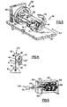
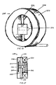
    1. A compact bar code scanning element for producing a scanning beam from a beam from a light source directed at the element, said scanning element comprising:
      a. a driving coil (234);
      b. a torsional flexural member (232) mounted across and supported at opposite ends by said driving coil (234) such that said member is free to torsionally flex relative to the driving coil;
      c. permanent magnet means (236) mounted on said torsional flexure member for movement therewith;
      d. a scanning mirror (235) in the path of the beam from the light source and mounted on said flexural member (232) for movement herewith; and
      e. means for generating a periodically changing drive signal introduced into the driving coil (234) to induce a periodically changing magnet field which interacts with said permanent magnet means (236) to cause said flexural member (232) and scanning mirror (235) to torsionally flex and cause the scanning mirror to move resulting in scanning of the beam.
    2. A module for use in a bar code reader comprising:
      a. light source; and
      b. a compact bar code scanning element as defined in claim 1.
    3. A compact bar code scanner as defined in claim 1, wherein flexural member (232) is vertically mounted on the driving coil (234) to cause a horizontal scanning of the scanning beam, with the vertical mounting eliminating any drooping of the flexural member.
    4. A compact bar code scanner as defined in claim 1, wherein a shock absorber material (242) mounts the flexural member on the driving coil, to absorb shocks in the event of dropping of the compact bar code scanner.
    5. A compact bar code scanner as defined in claim 1, wherein said scanning mirror (235) is mounted at one side and at the middle of the flexural member (232), and the permanent magnet means (236) is mounted at an opposite side and at the middle of the flexural member.
    6. A compact bar code scanner as defined in claim 4, wherein a scanning mirror and permanent magnet means holding member (238) is provided to mount the scanning mirror and permanent magnet means to the flexural member.
    EP02002293A 1991-11-04 1992-11-04 Compact bar code scanning arrangement Expired - Lifetime EP1209613B1 (en)

    Priority Applications (1)

    Application Number Priority Date Filing Date Title
    EP03011022A EP1345158A3 (en) 1991-11-04 1992-11-04 Compact bar code scanning arrangement

    Applications Claiming Priority (6)

    Application Number Priority Date Filing Date Title
    US78745891A 1991-11-04 1991-11-04
    US787458 1991-11-04
    US88473492A 1992-05-15 1992-05-15
    US884734 1992-05-19
    EP19920118897 EP0541065B1 (en) 1991-11-04 1992-11-04 Compact bar code scanning arrangement
    EP97202999A EP0827102B1 (en) 1991-11-04 1992-11-04 Compact bar code scanning arrangement

    Related Parent Applications (2)

    Application Number Title Priority Date Filing Date
    EP92118897.5 Division 1992-11-04
    EP97202999.5 Division 1997-09-30

    Related Child Applications (1)

    Application Number Title Priority Date Filing Date
    EP03011022.5 Division-Into 2003-05-19

    Publications (2)

    Publication Number Publication Date
    EP1209613A1 EP1209613A1 (en) 2002-05-29
    EP1209613B1 true EP1209613B1 (en) 2003-08-20

    Family

    ID=27120655

    Family Applications (4)

    Application Number Title Priority Date Filing Date
    EP97202999A Expired - Lifetime EP0827102B1 (en) 1991-11-04 1992-11-04 Compact bar code scanning arrangement
    EP02002293A Expired - Lifetime EP1209613B1 (en) 1991-11-04 1992-11-04 Compact bar code scanning arrangement
    EP03011022A Withdrawn EP1345158A3 (en) 1991-11-04 1992-11-04 Compact bar code scanning arrangement
    EP19920118897 Expired - Lifetime EP0541065B1 (en) 1991-11-04 1992-11-04 Compact bar code scanning arrangement

    Family Applications Before (1)

    Application Number Title Priority Date Filing Date
    EP97202999A Expired - Lifetime EP0827102B1 (en) 1991-11-04 1992-11-04 Compact bar code scanning arrangement

    Family Applications After (2)

    Application Number Title Priority Date Filing Date
    EP03011022A Withdrawn EP1345158A3 (en) 1991-11-04 1992-11-04 Compact bar code scanning arrangement
    EP19920118897 Expired - Lifetime EP0541065B1 (en) 1991-11-04 1992-11-04 Compact bar code scanning arrangement

    Country Status (5)

    Country Link
    EP (4) EP0827102B1 (en)
    AU (1) AU664207B2 (en)
    BR (1) BR9204366A (en)
    CA (1) CA2080784C (en)
    DE (3) DE69233171T2 (en)

    Families Citing this family (13)

    * Cited by examiner, † Cited by third party
    Publication number Priority date Publication date Assignee Title
    US5374817A (en) * 1988-05-11 1994-12-20 Symbol Technologies, Inc. Pre-objective scanner with flexible optical support
    US5506394A (en) * 1990-11-15 1996-04-09 Gap Technologies, Inc. Light beam scanning pen, scan module for the device and method of utilization
    ATE158662T1 (en) * 1993-05-07 1997-10-15 Opticon Sensors Europ BEAM DEFLECTION DEVICE
    EP0999513B1 (en) * 1993-09-14 2004-05-12 Symbol Technologies, Inc. Scanner with multiple scan units
    CA2132646A1 (en) * 1993-10-25 1995-04-26 Jerome Swartz Integrated scanner on a common substrate
    DE69520855T2 (en) * 1994-08-29 2001-08-30 Symbol Technologies Inc Portable optical scanning system for reading characters with different light reflection
    CA2166508C (en) * 1995-02-01 2008-04-01 Simon Bard Portable optical scanning and pointing systems
    FR2782210B1 (en) * 1998-08-06 2000-11-10 Gerard Michot PORTABLE AND AUTONOMOUS APPARATUS FOR REMOTE ACCESS TO THE CONTENT OF THE MEMORY OF A TRANSPONDER MODULE
    US6112993A (en) * 1998-09-03 2000-09-05 Psc Scanning, Inc. Flexible dither mount with rotation
    EP2481010B1 (en) * 2009-09-23 2016-01-27 Metrologic Instruments, Inc. Molded elastomeric flexural elements for use in a laser scanning assemblies and scanners, and methods of manufacturing, tuning and adjusting the same
    WO2018126529A1 (en) * 2017-01-06 2018-07-12 深圳市优博讯科技股份有限公司 Wearable hand-held mobile system
    CN107980111B (en) * 2017-01-06 2020-05-22 深圳市优博讯科技股份有限公司 Wearable handheld mobile system
    CN110363039A (en) * 2019-06-21 2019-10-22 上海翊视皓瞳信息科技有限公司 A kind of intelligence barcode scanning device and barcode scanning method

    Family Cites Families (13)

    * Cited by examiner, † Cited by third party
    Publication number Priority date Publication date Assignee Title
    FR2179469A5 (en) * 1972-04-07 1973-11-16 Hugin Kassaregister Ab
    US3978318A (en) * 1974-03-18 1976-08-31 Data General Corporation Hand-operated scanner
    US4230393A (en) * 1978-07-31 1980-10-28 Mfe Corporation Two-axis optical scanner
    US4421381A (en) * 1980-04-04 1983-12-20 Yokogawa Hokushin Electric Corp. Mechanical vibrating element
    GB2175705B (en) * 1985-05-24 1989-04-19 Stc Plc Dirigible reflector and mounting made of crystal material
    US4691212A (en) * 1985-11-14 1987-09-01 Xerox Corporation Piezoelectric optical beam deflector
    US4766299A (en) * 1986-03-28 1988-08-23 Spectra-Physics, Inc. Hand-mounted bar code reader
    US5144120A (en) * 1988-05-11 1992-09-01 Symbol Technologies, Inc. Mirrorless scanners with movable laser, optical and sensor components
    US4902083A (en) * 1988-05-31 1990-02-20 Reflection Technology, Inc. Low vibration resonant scanning unit for miniature optical display apparatus
    US5015831A (en) * 1988-11-07 1991-05-14 Photographic Sciences Corporation Scan modules for bar code readers and the like in which scan elements are flexurally supported
    US4935610A (en) * 1988-12-15 1990-06-19 Ncr Corporation Hand-held bar code reader
    US5168149A (en) * 1989-10-30 1992-12-01 Symbol Technologies, Inc. Scan pattern generators for bar code symbol readers
    US5099110A (en) * 1989-10-30 1992-03-24 Symbol Technologies, Inc. Power saving scanning arrangement

    Also Published As

    Publication number Publication date
    DE69233171D1 (en) 2003-09-25
    EP0541065B1 (en) 1999-01-13
    EP0827102B1 (en) 2003-07-09
    DE69228170T2 (en) 1999-08-19
    EP1345158A3 (en) 2003-11-19
    BR9204366A (en) 1993-05-11
    DE69228170D1 (en) 1999-02-25
    EP0827102A2 (en) 1998-03-04
    DE69233129D1 (en) 2003-08-14
    EP0541065A2 (en) 1993-05-12
    DE69233129T2 (en) 2004-04-15
    AU2717992A (en) 1993-05-06
    AU664207B2 (en) 1995-11-09
    EP1209613A1 (en) 2002-05-29
    DE69233171T2 (en) 2004-05-27
    EP0827102A3 (en) 2000-05-03
    CA2080784C (en) 2003-08-19
    EP0541065A3 (en) 1994-04-06
    CA2080784A1 (en) 1993-05-05
    EP1345158A2 (en) 2003-09-17

    Similar Documents

    Publication Publication Date Title
    US6010071A (en) Finger-mounted electro-optical scanner with on-board short range radio transmitter
    US5543610A (en) Compact bar code scanning arrangement
    EP0818750B1 (en) Slim scan module
    US5486944A (en) Scanner module for symbol scanning system
    US5404001A (en) Fiber optic barcode reader
    US5422469A (en) Fiber optic barcode readers using purely mechanical scanner oscillation
    US5168149A (en) Scan pattern generators for bar code symbol readers
    US5900617A (en) Optical scanning module having multiple-sided enclosure
    US5374817A (en) Pre-objective scanner with flexible optical support
    US20010027998A1 (en) Multi-dimensional scanning arrangement with U-shaped planar spring
    EP1209613B1 (en) Compact bar code scanning arrangement
    US6491225B1 (en) Electro-optical reader with electronic stylus
    EP0624852B1 (en) Scanner module for symbol scanning system
    US6616042B1 (en) Clamp assembly for detachably clamping spring in electro-optical system for reading indicia
    EP0809204A2 (en) Scanning arrangement

    Legal Events

    Date Code Title Description
    PUAI Public reference made under article 153(3) epc to a published international application that has entered the european phase

    Free format text: ORIGINAL CODE: 0009012

    AC Divisional application: reference to earlier application

    Ref document number: 827102

    Country of ref document: EP

    Ref document number: 541065

    Country of ref document: EP

    AK Designated contracting states

    Kind code of ref document: A1

    Designated state(s): DE FR GB IT

    RIN1 Information on inventor provided before grant (corrected)

    Inventor name: BARD, SIMON

    Inventor name: SWARTZ, JEROME SYMBOL TECHNOLOGIES INC.

    Inventor name: KATZ, JOSEPH

    Inventor name: STRATIENCO, ASKOLD SYMBOL TECHNOLOGIES INC.

    Inventor name: METLITSKY, BORIS

    Inventor name: KRICHEVER, MARK

    RIN1 Information on inventor provided before grant (corrected)

    Inventor name: SWARTZ, JEROME SYMBOL TECHNOLOGIES INC.

    Inventor name: METLITSKY, BORIS

    Inventor name: KATZ, JOSEPH

    Inventor name: STRATIENCO, ASKOLD C/O SYMBOL TECHNOLOGIES INC.

    Inventor name: KRICHEVER, MARK

    Inventor name: BARD, SIMON

    17P Request for examination filed

    Effective date: 20021128

    GRAH Despatch of communication of intention to grant a patent

    Free format text: ORIGINAL CODE: EPIDOS IGRA

    AKX Designation fees paid

    Designated state(s): DE FR GB IT

    GRAS Grant fee paid

    Free format text: ORIGINAL CODE: EPIDOSNIGR3

    GRAA (expected) grant

    Free format text: ORIGINAL CODE: 0009210

    AC Divisional application: reference to earlier application

    Ref document number: 0827102

    Country of ref document: EP

    Kind code of ref document: P

    Ref document number: 0541065

    Country of ref document: EP

    Kind code of ref document: P

    AK Designated contracting states

    Designated state(s): DE FR GB IT

    REG Reference to a national code

    Ref country code: GB

    Ref legal event code: FG4D

    REF Corresponds to:

    Ref document number: 69233171

    Country of ref document: DE

    Date of ref document: 20030925

    Kind code of ref document: P

    ET Fr: translation filed
    PLBE No opposition filed within time limit

    Free format text: ORIGINAL CODE: 0009261

    STAA Information on the status of an ep patent application or granted ep patent

    Free format text: STATUS: NO OPPOSITION FILED WITHIN TIME LIMIT

    26N No opposition filed

    Effective date: 20040524

    PGFP Annual fee paid to national office [announced via postgrant information from national office to epo]

    Ref country code: FR

    Payment date: 20101109

    Year of fee payment: 19

    PGFP Annual fee paid to national office [announced via postgrant information from national office to epo]

    Ref country code: DE

    Payment date: 20101130

    Year of fee payment: 19

    PGFP Annual fee paid to national office [announced via postgrant information from national office to epo]

    Ref country code: GB

    Payment date: 20101022

    Year of fee payment: 19

    Ref country code: IT

    Payment date: 20101119

    Year of fee payment: 19

    GBPC Gb: european patent ceased through non-payment of renewal fee

    Effective date: 20111104

    REG Reference to a national code

    Ref country code: FR

    Ref legal event code: ST

    Effective date: 20120731

    PG25 Lapsed in a contracting state [announced via postgrant information from national office to epo]

    Ref country code: IT

    Free format text: LAPSE BECAUSE OF NON-PAYMENT OF DUE FEES

    Effective date: 20111104

    REG Reference to a national code

    Ref country code: DE

    Ref legal event code: R119

    Ref document number: 69233171

    Country of ref document: DE

    Effective date: 20120601

    PG25 Lapsed in a contracting state [announced via postgrant information from national office to epo]

    Ref country code: GB

    Free format text: LAPSE BECAUSE OF NON-PAYMENT OF DUE FEES

    Effective date: 20111104

    PG25 Lapsed in a contracting state [announced via postgrant information from national office to epo]

    Ref country code: FR

    Free format text: LAPSE BECAUSE OF NON-PAYMENT OF DUE FEES

    Effective date: 20111130

    PG25 Lapsed in a contracting state [announced via postgrant information from national office to epo]

    Ref country code: DE

    Free format text: LAPSE BECAUSE OF NON-PAYMENT OF DUE FEES

    Effective date: 20120601