EP1207532A2 - Dynamic vibration absorber for a disk player - Google Patents
Dynamic vibration absorber for a disk player Download PDFInfo
- Publication number
- EP1207532A2 EP1207532A2 EP01309162A EP01309162A EP1207532A2 EP 1207532 A2 EP1207532 A2 EP 1207532A2 EP 01309162 A EP01309162 A EP 01309162A EP 01309162 A EP01309162 A EP 01309162A EP 1207532 A2 EP1207532 A2 EP 1207532A2
- Authority
- EP
- European Patent Office
- Prior art keywords
- deck plate
- disk
- absorber
- mass body
- dynamic
- Prior art date
- Legal status (The legal status is an assumption and is not a legal conclusion. Google has not performed a legal analysis and makes no representation as to the accuracy of the status listed.)
- Granted
Links
Images


Classifications
-
- G—PHYSICS
- G11—INFORMATION STORAGE
- G11B—INFORMATION STORAGE BASED ON RELATIVE MOVEMENT BETWEEN RECORD CARRIER AND TRANSDUCER
- G11B33/00—Constructional parts, details or accessories not provided for in the other groups of this subclass
- G11B33/02—Cabinets; Cases; Stands; Disposition of apparatus therein or thereon
- G11B33/08—Insulation or absorption of undesired vibrations or sounds
Definitions
- the present invention relates to a dynamic vibration absorber for a disk player, and more particularly, to a dynamic vibration absorber for a disk player that reduces vibration generated when a recording medium spins.
- a disk player is an apparatus that records and/or reproduces information to and from a disk such as a compact disk (CD), a CD-Rom, a digital video disk (DVD), a DVD-Rom, a CD-RW, and a combo disk.
- This apparatus needs to protect the disk and an optical pickup therein from both outer shock and inner vibration.
- a conventional disk player generally includes a deck base disposed in a housing of the disk player, a deck plate movably disposed on the deck base, a spindle motor disposed on the deck plate to generate energy to spin the disk, a turn-table connected to a pivot shaft of the spindle motor to support the disk, a clamper disposed at the upper part of the housing corresponding to the turn-table to clamp the disk on the turn-table, and an optical pickup movably connected to the deck plate to move radially across the disk to record and/or reproduce information to and from the disk.
- a buffering member is disposed between the deck base and the deck plate to protect the disk and the optical pickup from an outer shock.
- an auto-ball-balancer has been developed to balance an eccentric mass by setting up balls at opposite side of the mass eccentricity.
- the auto-ball-balancer includes a circular accommodating portion in a spinning body like the turn-table and the spindle motor, and the auto-ball-balancer is realized by placing balls having a predetermined mass in the accommodating portion.
- the auto-ball-balancer is only effective in balancing an eccentric disk.
- the auto-ball-balancer when the auto-ball-balancer is applied to the eccentric disk, the auto-ball-balancer also causes a problem by increasing the vibration in a resonance band.
- a deck plate is well balanced, it possesses a natural frequency in accordance with its design and material.
- vibration is generated around the natural frequency, there is a problem of an increased vibration due to a resonance effect.
- it is difficult for the optical pickup to record and/or reproduce data to and from the disk. Due to this problem, there is a limitation in the increase in recording density of the disk.
- the vibration can dramatically affect peripheral devices such as a hard disk drive (HDD) and a floppy disk drive (FDD).
- HDD hard disk drive
- FDD floppy disk drive
- a dynamic vibration absorber for a disk player that records and/or reproduces data to and from a disk, comprising: a deck base; a deck plate movably supported by said deck base to support a spindle motor that spins a disk; and a mass body disposed around said deck plate; and a flexibly changeable connection member that connects said deck plate and said mass body so as to allow a reciprocal action between said mass body and said deck plate, wherein the reciprocal action of said mass body and said connection member reduces a vibration generated in use when the disk spins.
- supporting members are provided to support said deck plate at predetermined support points which define a figure, and said mass body is placed at an outermost point from a geometrical center of the figure defined by the supporting points.
- said mass body is disposed at a predetermined place on the deck plate that has a largest vibration shift from a geometrical centre of the figure defined by the supporting points.
- connection member comprises: a body that is flexibly changeable by an external force and has an internal space to allow compression; a first flange portion extending from the body to support said mass body; and a second flange portion extending from the body to fit into said deck plate to be supported by said deck plate.
- said deck plate has a connection hole through which the second flange portion extends to be supported by said deck plate.
- said mass body comprises a metallic ring having a connection hole having a size that is smaller than a size of the first flange portion so as to be supported by the first flange portion.
- said mass body comprises a metallic plate having a connection opening cut from one end to allow insertion above the first flange.
- said mass body is disposed above or below said deck plate to reduce a vibration in an upper and a lower direction relative to said deck plate.
- said mass body is disposed on a side of said deck plate to reduce a vibration in a direction perpendicular to the side of said deck plate.
- the dynamic vibration absorber may comprise additional mass bodies and corresponding connection members attached to the deck plate.
- a supporting member to support said deck plate at a supporting point, and a viscoelastic member disposed at the supporting point of said deck plate to reduce an effect of an outer shock transmitted between said deck plate and said deck base.
- said mass body and said connection member comprise a combined member using an injection molding process.
- a dynamic absorber for use in a disk player that records and/or reproduces data to and from a disk, which includes a movable plate that supports a spindle motor used to spin the disk, the absorber comprising: a flexible connection member adapted to be connected to the movable plate; and a mass body connected to said connection member, wherein said connection member and said mass body move relative to the movable plate so as to absorb a vibration generated when the disk spins.
- connection member and said mass body move in a non-parallel direction to an axis of rotation of the disk to absorb a vibration along the axis of rotation of the disk.
- said connection member and said mass body move in a direction perpendicular to the axis of rotation of the disk.
- the dynamic absorber has roughly a same natural resonance frequency as the movable plate.
- said mass body has a mass and said connection member has a spring constant such that the dynamic absorber has roughly the same natural resonance frequency as the movable plate.
- a recording and/or reproducing apparatus to record and/or reproduce data to and from a disk, comprising: a housing; a deck plate movably supported within said housing, said deck plate having a predetermined frequency; an optical head movably supported within said housing to record and/or reproduce the data to and from the disk; a spindle motor supported by said deck plate and which spins the disk; and a dynamic absorber having a frequency that roughly corresponds to the predetermined frequency of said deck plate so as to absorb a vibration generated when the disk spins.
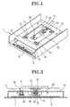
- a disk player comprises a deck base 10 disposed in a housing 1, a deck plate 20 disposed in the deck base 10, and a dynamic vibration absorber included in the deck plate 20.
- Various electrical peripheral devices including a circuit board 3 and a connector 5 are also disposed in the housing 1.
- the deck base 10 is a chassis structure (i.e., a metal plate fixed in the housing 1) and has an accommodating portion 11 to movably hold and support the deck plate 20.
- the accommodation portion 11 is a predetermined space formed by partly cutting the deck base 10.
- the dynamic vibration absorber is attached to the deck plate 20 and includes a mass body 30 disposed below the deck plate 20, and a connection member 40 connecting the deck plate 20 and the mass body 30.
- the deck plate 20 is movably disposed in the accommodation portion 11 of the deck base 10.
- the deck base 10 has supporting portions 12, 13, 14 disposed corresponding to predetermined supporting points P1, P2, P3 to support the deck plate 20.
- a damping member 15 is disposed to prevent an outer shock from transferring to the deck plate 20 through the deck base 10.
- the damping member 15 is generally viscoelastic rubber or a spring, and is inserted between the deck base 10 and the deck plate 20.
- the deck plate 20 moves relative to the deck base 10 using the flexibility of the damping member 15.
- a spindle motor 53 and an optical pickup 55 are disposed on the deck plate 20.
- a turntable 51, on which a disk D is settled, is pivotably formed on a rotating shaft of the spindle motor 53.
- the optical pickup 55 is movable in the radial direction of the disk D while on the turntable 51 using a transferring mechanism, and information is recorded and/or reproduced by projecting light from the optical pickup 55 to and detecting the reflected light from the disk D.
- the disk D is inserted into the housing 1 in a disk tray (not shown), and then the disk D is settled on the turntable 51 and is clamped by a clamper 57 disposed at the upper part of the housing 1.
- a clamper 57 disposed at the upper part of the housing 1.
- the disk D can be loaded by elevating the turntable 51 and the spindle motor 53, or by elevating or lowering the disk tray onto the turntable 51.
- the deck plate 20 is a metallic or plastic plate, and has a natural resonance frequency.
- the mass body 30 reduces the resonance generated by the resonance frequency of the deck plate 20 when the disk D spins through a reciprocal action using the connection member 40 . It is preferable that the mass body 30 is disposed above or below the deck plate 20, which effectively reduces the vibration in an up and down direction.
- the up and down direction is a focusing direction of the optical pickup 55 moveably mounted on the deck plate 20.
- the mass body 30 is a metallic circular plate having a predetermined thickness and mass. Moreover, the mass body 30 has a connection opening 31 cut in a U type from one side. The connection opening 31 allows the mass body 30 to be easily connected with the connection member 40. Therefore, using the connection opening 31, the mass body 30 is connected with the connection member 40 very easily by inserting the connection opening 31 into the connection member 40.
- a ring-type mass body 30' having a connection hole 31' is used instead of the mass body 30 shown in Figure 3.
- the connection hole 31' is connected enclosed within the mass body 30', once the connection member 40 is inserted, easy separation can be prevented.
- the weight and the thickness of the mass body 30 and 30' will be described later in greater detail.
- the weight and thickness are selected with an appropriate value considering the mass (M) of the deck plate 20, the spring constant K of the connection member 40, and the vibration frequency that is problematic in the disk drive.
- connection member 40 is connected to the mass body 30 disposed below the deck plate 20.
- the connection member 40 has a shape of an hourglass and includes a body 41 having a predetermined space 41a capable of a slackness in accordance with an internal pressure.
- the connection member 40 also has first and second flange portions 45 and 46 extending from first and second neck portions 42 and 43, which extends symmetrically on both sides of the body 41.
- the space 41a within the body 41 is connected to the outside through a hole 40a that extends through the flange portions 45 and 46.
- the body 41 is a cylinder type and the action of the internal pressure and slackness can be performed repeatedly as it flexibly changes by an external force. Specifically, the air in the space 41a is discharged externally and drawn internally through the hole 40a, which absorbs the shock and the vibration from the outside.
- the mass body 30 is inserted into the first neck portion 42 and is supported by the first flange portion 45.
- the mass body 30 is prevented from being separated from the first neck portion 42.
- the length and the diameter of the first neck portion 42 have a size corresponding to the connection opening 31 of the mass body 30 and the thickness of the mass body 30.
- the connection member 40 is connected to the deck plate 20, using a connection hole 20a formed at the deck plate 20 to receive the second neck portion 43.
- the second flange portion 46 extends from the second neck portion 43 to restrain the connection member 40 and prevent the connection member 40 from being separated from the connection hole 20a.
- connection member 40 is made from a viscoelastic silicon having a predetermined spring constant K corresponding to the natural vibration frequency of the deck plate 20.
- connection member could also be made from a spring.
- connection member 40 has a sufficient degree of stiffness considering the factors such as elastic deformation and durability.
- the mass body 30 and the connection member 40 are disposed at the point of largest amplitude of vibration of the deck plate 20 according to the positions of supporting points P1, P2, P3. Specifically, it is preferable that the mass body 30 and the connection member 40 are disposed at the outermost point D of the deck plate 20, where the outermost point D is the farthest point from a geometrical center C of a predetermined figure S formed by the supporting points P1, P2, P3. In the shown example in Figure 6A, the predetermined figure S is a triangle. By disposing the mass body 30 and the connection member 40 at the point D, the mass body 30 and the connection member 40 are placed at the farthest point from the center C to reduce vibration and shock at the point D, at which the largest vibration and shock is experienced.
- a plurality of mass bodies 30 and corresponding connection members 40 are disposed around the deck plate20.
- the plurality of mass bodies 30 and connection members 40 can be formed at other points beyond the point D. For example, they can be formed at the opposite point of the point D such that the center C is at the center. Further, the plurality of mass bodies 30 and connection members 40 can be disposed at the points in descending order of distance from the center C.
- mass body 30 is shown as disposed below the deck plate 20, it is understood that the mass body 30 can be disposed above the deck plate 20. Further, the mass body 30 can be disposed at the point of the largest vibration shift from the geometrical center C. Since the point of the largest vibration shift of the deck plate 20 may not be the farthest point from the center C, it can be found by separately measuring the vibration shift of the deck plate 20. It is further understood that the mass body 30 and the connection member 40 can be formed as a combined member through techniques such as injection molding.
- FIGS. 7-10 The operation of a dynamic vibration absorber for a disk player of an embodiment of the present invention will be described in detail using FIGS. 7-10.
- Figures 7 and 8 show the vibration feature of disk players with and without the dynamic vibration absorber of the present invention.
- Figure 7 is a graph measuring the frequency of a deformed wobble disk which has an RPM that increases from 0 to 10000 using the spindle motor 53 excluding the deck plate 20.
- comparison example A1 lacks the dynamic vibration absorber and generates resonance around 60Hz with no influence of the deck plate 20 and the optical pickup 55.
- experimental example A2 which has the dynamic vibration absorber, the resonance has been largely reduced around 60Hz. In other words, by a repeated reciprocal action of the connection member 40 and the mass body 30, the vibration at roughly the resonance frequency of the disk D has been effectively reduced.
- Figure 8 is a graph measuring the vibration volume of the deck plate 20 under the same condition as the deck plate 20 in the Figure 7.
- comparison example B1 which lacks the dynamic vibration absorber, has a vibration volume that increases at around 60Hz.
- the vibration volume of the deck plate 20 has a great influence on the operation of the optical pickup 55 due to its amplifying the vibration of the disk D.
- the vibration volume for the resonance frequency of the deck plate 20 has been effectively reduced.
- the reduced volume of the vibration energy which reveals the volume of the vibration energy absorbed by the reciprocal action of the connection member 40 and the mass body 30, is the region designated by cross-hatching in Figure 8.
- the resonance frequency due to the reciprocal action of the connection member 40 and the mass body 30 is found by measuring the mass of the mass body 30 and determining the spring constant K of the connection member 40. These values are determined using a computer simulation through a well known FEM (Finite Element Method). For example, for the dynamic vibration absorber to have the natural vibration frequency of about 60Hz, the spring constant K of the connection member 40 is about 466 (kg/sec ⁇ 2), and the mass of the mass body 30 is about 3.28g, according to the FEM (Finite Element Method). In this case, the mass body 30 can be manufactured as a circular plate having a thickness of 2mm and a diameter of 18mm.
- comparison example C1 which lacks the dynamic vibration absorber, generates structural noise due to the vibration by resonance at 16X speed (62Hz, about 3600RPM).
- 16X speed 62Hz, about 3600RPM
- the natural vibration frequency of the wobble disk and harmonic natural vibration frequency over 3X speed are the same, which cause the structural noise to be generated.
- noise of about 41 ⁇ 42dBA was detected.
- the dynamic vibration absorber is shown to have absorbed most of the vibration due to the resonance.
- the vibration volume of the deck plate 20 and the disk D is considerably reduced, and the structural noise is substantially reduced.
- noise of about 35 ⁇ 36dBA, which is less than the comparison example C1 was detected.
- the detected value is about 5.5dBA lower than the noise detected from comparison example C1.
- the dynamic vibration absorber has a large effect on reducing the structural noise.
- the resonance frequency is changed in accordance with a variation in the model of the deck plate 20, by designing the resonance frequency by the reciprocal action of the connection member 40 and the mass body 30 with the FEM (Finite Element Method) to correspond to the resonance frequency of the different deck plate 20, the appropriate dynamic vibration absorber can be manufactured and applied.
- FEM Finite Element Method
- the disk D is in a vertical-type disk player that accommodates the disk D while standing on a supporting side G.
- a deck plate 200 is accommodated vertically, and includes a mass body 210 and a connection member 230.
- the mass body 210 is disposed below a lower side 201 of the deck plate 200.
- the connection member 230 connects the mass body 210 to the side 201.
- a spindle motor 250 which is disposed at the deck plate 200, spins, the increased vibration for the increase of the natural frequency of the deck plate 200 and the natural frequency of the disk D can be effectively reduced in the same way as described above.
- another mass body 310 and another connection member 330 are capable of moving in a right and left direction of the deck plate 200.
- the dynamic vibration absorber of the present invention is designed with a simple structure and used such that, when the disk spins, the vibration by the resonance frequency of the deck plate can be effectively reduced. Further, by disposing the mass body at a predetermined point corresponding to the largest vibration amplitude of the deck plate, the vibration-absorbing effect of the dynamic vibration absorber can be maximized. Therefore, by stabilizing the dynamic feature of the deck plate and the disk, the operation of the optical pickup can be smoothly performed, and servo control can be easily done. In addition, ampere wastage is reduced by reducing the load of the spindle motor, which also extends the life span of the machine. Moreover, the user can use the product with a pleasant atmosphere of low noise and vibration, further upgrading the refinement of the product.
Landscapes
- Vibration Prevention Devices (AREA)
- Casings For Electric Apparatus (AREA)
- Holding Or Fastening Of Disk On Rotational Shaft (AREA)
Abstract
Description
- The present invention relates to a dynamic vibration absorber for a disk player, and more particularly, to a dynamic vibration absorber for a disk player that reduces vibration generated when a recording medium spins.
- Generally, a disk player is an apparatus that records and/or reproduces information to and from a disk such as a compact disk (CD), a CD-Rom, a digital video disk (DVD), a DVD-Rom, a CD-RW, and a combo disk. This apparatus needs to protect the disk and an optical pickup therein from both outer shock and inner vibration.
- A conventional disk player generally includes a deck base disposed in a housing of the disk player, a deck plate movably disposed on the deck base, a spindle motor disposed on the deck plate to generate energy to spin the disk, a turn-table connected to a pivot shaft of the spindle motor to support the disk, a clamper disposed at the upper part of the housing corresponding to the turn-table to clamp the disk on the turn-table, and an optical pickup movably connected to the deck plate to move radially across the disk to record and/or reproduce information to and from the disk. In the above construction, a buffering member is disposed between the deck base and the deck plate to protect the disk and the optical pickup from an outer shock.
- However, since the centers of rotation and gravity of a conventional disk do not always correspond due to manufacturing errors, an inner vibration results and generates whirling. Because of the inner vibration, it is difficult to prevent the generation of idle revolution of a rotating shaft of the spindle motor.
- Due to this problem, an auto-ball-balancer has been developed to balance an eccentric mass by setting up balls at opposite side of the mass eccentricity. The auto-ball-balancer includes a circular accommodating portion in a spinning body like the turn-table and the spindle motor, and the auto-ball-balancer is realized by placing balls having a predetermined mass in the accommodating portion. However, the auto-ball-balancer is only effective in balancing an eccentric disk. In addition, when the auto-ball-balancer is applied to the eccentric disk, the auto-ball-balancer also causes a problem by increasing the vibration in a resonance band.
- In addition, although a deck plate is well balanced, it possesses a natural frequency in accordance with its design and material. Thus, when vibration is generated around the natural frequency, there is a problem of an increased vibration due to a resonance effect. In this case, it is difficult for the optical pickup to record and/or reproduce data to and from the disk. Due to this problem, there is a limitation in the increase in recording density of the disk. Moreover, the vibration can dramatically affect peripheral devices such as a hard disk drive (HDD) and a floppy disk drive (FDD).
- It is an aim of the present invention to provide a dynamic vibration absorber for a disk player to effectively reduce a vibration generated when a disk spins. Additional aims and advantages of the invention will be set forth in part in the description which follows and, in part, will be obvious from the description, or may be learned by practice of the invention.
- According to a first aspect of the present invention there is provided a dynamic vibration absorber for a disk player that records and/or reproduces data to and from a disk, comprising: a deck base; a deck plate movably supported by said deck base to support a spindle motor that spins a disk; and a mass body disposed around said deck plate; and a flexibly changeable connection member that connects said deck plate and said mass body so as to allow a reciprocal action between said mass body and said deck plate, wherein the reciprocal action of said mass body and said connection member reduces a vibration generated in use when the disk spins.
- In one embodiment, supporting members are provided to support said deck plate at predetermined support points which define a figure, and said mass body is placed at an outermost point from a geometrical center of the figure defined by the supporting points. Alternatively, said mass body is disposed at a predetermined place on the deck plate that has a largest vibration shift from a geometrical centre of the figure defined by the supporting points.
- Preferably, said connection member comprises: a body that is flexibly changeable by an external force and has an internal space to allow compression; a first flange portion extending from the body to support said mass body; and a second flange portion extending from the body to fit into said deck plate to be supported by said deck plate.
- Preferably, said deck plate has a connection hole through which the second flange portion extends to be supported by said deck plate. Preferably, said mass body comprises a metallic ring having a connection hole having a size that is smaller than a size of the first flange portion so as to be supported by the first flange portion. Alternatively, said mass body comprises a metallic plate having a connection opening cut from one end to allow insertion above the first flange.
- Preferably, said mass body is disposed above or below said deck plate to reduce a vibration in an upper and a lower direction relative to said deck plate. Alternatively, said mass body is disposed on a side of said deck plate to reduce a vibration in a direction perpendicular to the side of said deck plate.
- The dynamic vibration absorber may comprise additional mass bodies and corresponding connection members attached to the deck plate.
- Preferably, there is provided a supporting member to support said deck plate at a supporting point, and a viscoelastic member disposed at the supporting point of said deck plate to reduce an effect of an outer shock transmitted between said deck plate and said deck base.
- In a preferred embodiment, said mass body and said connection member comprise a combined member using an injection molding process.
- According to a second aspect of the present invention there is provided a dynamic absorber for use in a disk player that records and/or reproduces data to and from a disk, which includes a movable plate that supports a spindle motor used to spin the disk, the absorber comprising: a flexible connection member adapted to be connected to the movable plate; and a mass body connected to said connection member, wherein said connection member and said mass body move relative to the movable plate so as to absorb a vibration generated when the disk spins.
- In one embodiment, said connection member and said mass body move in a non-parallel direction to an axis of rotation of the disk to absorb a vibration along the axis of rotation of the disk. In another embodiment, said connection member and said mass body move in a direction perpendicular to the axis of rotation of the disk. Preferably, the dynamic absorber has roughly a same natural resonance frequency as the movable plate. Preferably, said mass body has a mass and said connection member has a spring constant such that the dynamic absorber has roughly the same natural resonance frequency as the movable plate.
- According to a third aspect of the present invention there is provided a recording and/or reproducing apparatus to record and/or reproduce data to and from a disk, comprising: a housing; a deck plate movably supported within said housing, said deck plate having a predetermined frequency; an optical head movably supported within said housing to record and/or reproduce the data to and from the disk; a spindle motor supported by said deck plate and which spins the disk; and a dynamic absorber having a frequency that roughly corresponds to the predetermined frequency of said deck plate so as to absorb a vibration generated when the disk spins.
- For a better understanding of the invention, and to show how embodiments of the same may be carried into effect, reference will now be made, by way of example, to the accompanying diagrammatic drawings in which:
- Figure 1 is a schematic perspective view showing a dynamic vibration absorber for a disk player according to an embodiment of the present invention;
- Figure 2 is a sectional view of the disk player taken along the line I-I of Figure 1;
- Figure 3 is a perspective view of the mass body of Figure 2;
- Figure 4 is a perspective view showing the mass body of Figure 3 according to another embodiment of the present invention;
- Figure 5 is a sectional end perspective view showing the connection member of Figure 2;
- Figure 6A is a schematic plan view showing the dynamic vibration absorber of Figure 2;
- Figure 6B is a schematic plan view showing a plurality of the dynamic vibration absorbers according to an embodiment of the present invention;
- Figures 7 and 8 are graphs comparing the vibration frequency volume of a disk player using the dynamic vibration absorber using an embodiment of the present invention and that of a conventional disk player;
- Figure 9 is a graph showing a theoretical vibration absorbing effect of a dynamic vibration absorber according to an embodiment of the present invention;
- Figure 10 is a graph comparing the noise resulting from an experiment using an embodiment of the present invention and the noise resulting from a conventional disk player; and
- Figure 11 is a sectional view showing a dynamic vibration absorber for a disk player of another embodiment of the present invention.
-
- Referring to Figure 1, a disk player comprises a
deck base 10 disposed in ahousing 1, adeck plate 20 disposed in thedeck base 10, and a dynamic vibration absorber included in thedeck plate 20. Various electrical peripheral devices including acircuit board 3 and aconnector 5 are also disposed in thehousing 1. - The
deck base 10 is a chassis structure (i.e., a metal plate fixed in the housing 1) and has anaccommodating portion 11 to movably hold and support thedeck plate 20. Theaccommodation portion 11 is a predetermined space formed by partly cutting thedeck base 10. - As shown in Figure 2, the dynamic vibration absorber is attached to the
deck plate 20 and includes amass body 30 disposed below thedeck plate 20, and aconnection member 40 connecting thedeck plate 20 and themass body 30. Thedeck plate 20 is movably disposed in theaccommodation portion 11 of thedeck base 10. Thedeck base 10 has supportingportions deck plate 20. At these supporting points P1, P2, P3, adamping member 15 is disposed to prevent an outer shock from transferring to thedeck plate 20 through thedeck base 10. Thedamping member 15 is generally viscoelastic rubber or a spring, and is inserted between thedeck base 10 and thedeck plate 20. Thedeck plate 20 moves relative to thedeck base 10 using the flexibility of thedamping member 15. - In addition, a
spindle motor 53 and anoptical pickup 55 are disposed on thedeck plate 20. Aturntable 51, on which a disk D is settled, is pivotably formed on a rotating shaft of thespindle motor 53. Theoptical pickup 55 is movable in the radial direction of the disk D while on theturntable 51 using a transferring mechanism, and information is recorded and/or reproduced by projecting light from theoptical pickup 55 to and detecting the reflected light from the disk D. - The disk D is inserted into the
housing 1 in a disk tray (not shown), and then the disk D is settled on theturntable 51 and is clamped by aclamper 57 disposed at the upper part of thehousing 1. However, it is understood that there are many ways to load and clamp the disk D on theturntable 51. For example, the disk D can be loaded by elevating theturntable 51 and thespindle motor 53, or by elevating or lowering the disk tray onto theturntable 51. - The
deck plate 20 is a metallic or plastic plate, and has a natural resonance frequency. Themass body 30 reduces the resonance generated by the resonance frequency of thedeck plate 20 when the disk D spins through a reciprocal action using theconnection member 40 . It is preferable that themass body 30 is disposed above or below thedeck plate 20, which effectively reduces the vibration in an up and down direction. The up and down direction is a focusing direction of theoptical pickup 55 moveably mounted on thedeck plate 20. - According to an embodiment of the invention shown in Figure 3, the
mass body 30 is a metallic circular plate having a predetermined thickness and mass. Moreover, themass body 30 has aconnection opening 31 cut in a U type from one side. Theconnection opening 31 allows themass body 30 to be easily connected with theconnection member 40. Therefore, using theconnection opening 31, themass body 30 is connected with theconnection member 40 very easily by inserting theconnection opening 31 into theconnection member 40. - According to an embodiment of the invention shown in Figure 4, instead of the
mass body 30 shown in Figure 3, a ring-type mass body 30' having a connection hole 31' is used. In this case, since the connection hole 31' is connected enclosed within the mass body 30', once theconnection member 40 is inserted, easy separation can be prevented. - For
mass bodies 30 and 30', the weight and the thickness of themass body 30 and 30' will be described later in greater detail. However, the weight and thickness are selected with an appropriate value considering the mass (M) of thedeck plate 20, the spring constant K of theconnection member 40, and the vibration frequency that is problematic in the disk drive. - As shown in Figure 5, the
connection member 40 is connected to themass body 30 disposed below thedeck plate 20. Theconnection member 40 has a shape of an hourglass and includes abody 41 having apredetermined space 41a capable of a slackness in accordance with an internal pressure. Theconnection member 40 also has first andsecond flange portions second neck portions body 41. Thespace 41a within thebody 41 is connected to the outside through ahole 40a that extends through theflange portions - In the above construction, the
body 41 is a cylinder type and the action of the internal pressure and slackness can be performed repeatedly as it flexibly changes by an external force. Specifically, the air in thespace 41a is discharged externally and drawn internally through thehole 40a, which absorbs the shock and the vibration from the outside. Themass body 30 is inserted into thefirst neck portion 42 and is supported by thefirst flange portion 45. - The
mass body 30 is prevented from being separated from thefirst neck portion 42. Thus, it is preferable that the length and the diameter of thefirst neck portion 42 have a size corresponding to the connection opening 31 of themass body 30 and the thickness of themass body 30. Moreover, theconnection member 40 is connected to thedeck plate 20, using aconnection hole 20a formed at thedeck plate 20 to receive thesecond neck portion 43. Thesecond flange portion 46 extends from thesecond neck portion 43 to restrain theconnection member 40 and prevent theconnection member 40 from being separated from theconnection hole 20a. - It is preferable that the
connection member 40 is made from a viscoelastic silicon having a predetermined spring constant K corresponding to the natural vibration frequency of thedeck plate 20. However, it is understood that the connection member could also be made from a spring. In addition, it is advisable that theconnection member 40 has a sufficient degree of stiffness considering the factors such as elastic deformation and durability. - As shown in Figure 6A, the
mass body 30 and theconnection member 40 are disposed at the point of largest amplitude of vibration of thedeck plate 20 according to the positions of supporting points P1, P2, P3. Specifically, it is preferable that themass body 30 and theconnection member 40 are disposed at the outermost point D of thedeck plate 20, where the outermost point D is the farthest point from a geometrical center C of a predetermined figure S formed by the supporting points P1, P2, P3. In the shown example in Figure 6A, the predetermined figure S is a triangle. By disposing themass body 30 and theconnection member 40 at the point D, themass body 30 and theconnection member 40 are placed at the farthest point from the center C to reduce vibration and shock at the point D, at which the largest vibration and shock is experienced. - According to another embodiment of the invention shown in Figure 6B, a plurality of
mass bodies 30 andcorresponding connection members 40 are disposed around the deck plate20. The plurality ofmass bodies 30 andconnection members 40 can be formed at other points beyond the point D. For example, they can be formed at the opposite point of the point D such that the center C is at the center. Further, the plurality ofmass bodies 30 andconnection members 40 can be disposed at the points in descending order of distance from the center C. - In addition, while the
mass body 30 is shown as disposed below thedeck plate 20, it is understood that themass body 30 can be disposed above thedeck plate 20. Further, themass body 30 can be disposed at the point of the largest vibration shift from the geometrical center C. Since the point of the largest vibration shift of thedeck plate 20 may not be the farthest point from the center C, it can be found by separately measuring the vibration shift of thedeck plate 20. It is further understood that themass body 30 and theconnection member 40 can be formed as a combined member through techniques such as injection molding. - The operation of a dynamic vibration absorber for a disk player of an embodiment of the present invention will be described in detail using FIGS. 7-10.
- Figures 7 and 8 show the vibration feature of disk players with and without the dynamic vibration absorber of the present invention. Figure 7 is a graph measuring the frequency of a deformed wobble disk which has an RPM that increases from 0 to 10000 using the
spindle motor 53 excluding thedeck plate 20. As shown in Figure 7, comparison example A1 lacks the dynamic vibration absorber and generates resonance around 60Hz with no influence of thedeck plate 20 and theoptical pickup 55. On the other hand, in experimental example A2, which has the dynamic vibration absorber, the resonance has been largely reduced around 60Hz. In other words, by a repeated reciprocal action of theconnection member 40 and themass body 30, the vibration at roughly the resonance frequency of the disk D has been effectively reduced. - Figure 8 is a graph measuring the vibration volume of the
deck plate 20 under the same condition as thedeck plate 20 in the Figure 7. As shown in Figure 8, comparison example B1, which lacks the dynamic vibration absorber, has a vibration volume that increases at around 60Hz. The vibration volume of thedeck plate 20 has a great influence on the operation of theoptical pickup 55 due to its amplifying the vibration of the disk D. For experimental example B3, which has the dynamic vibration absorber, the vibration volume for the resonance frequency of thedeck plate 20 has been effectively reduced. The reduced volume of the vibration energy, which reveals the volume of the vibration energy absorbed by the reciprocal action of theconnection member 40 and themass body 30, is the region designated by cross-hatching in Figure 8. Thus, when the dynamic vibration absorber is used, not only is the strong vibration by resonance of thedeck plate 20 eliminated, but the structural bone noise caused by the vibration can also be eliminated. - Through the above experiment, even though the spinning speed of the disk D is increased, if the disk applies the dynamic vibration absorber having a resonance frequency corresponding to the problematic vibration frequency, then the generation or amplifying of vibration of the
deck plate 20 can be effectively prevented. - On the other hand, to design the dynamic vibration absorber corresponding to the
deck plate 20, the resonance frequency due to the reciprocal action of theconnection member 40 and themass body 30 is found by measuring the mass of themass body 30 and determining the spring constant K of theconnection member 40. These values are determined using a computer simulation through a well known FEM (Finite Element Method). For example, for the dynamic vibration absorber to have the natural vibration frequency of about 60Hz, the spring constant K of theconnection member 40 is about 466 (kg/sec^2), and the mass of themass body 30 is about 3.28g, according to the FEM (Finite Element Method). In this case, themass body 30 can be manufactured as a circular plate having a thickness of 2mm and a diameter of 18mm. The vibration reducing effect using the theoretical dynamic vibration absorber obtained using this result can be easily checked through an experimental value by a simulation as shown in Figure 9. In other words, using computer simulations, a theoretical dynamic vibration absorber can be designed to effectively absorb the vibration of thedeck plate 20 having a resonance frequency at around 60Hz. - Moreover, as shown in TABLE 1 and Figure 10, comparison example C1, which lacks the dynamic vibration absorber, generates structural noise due to the vibration by resonance at 16X speed (62Hz, about 3600RPM). This results in the noise shown in Figure 10. As such, it can be inferred that the natural vibration frequency of the wobble disk and harmonic natural vibration frequency over 3X speed are the same, which cause the structural noise to be generated. In this case, noise of about 41 ∼ 42dBA was detected.
Spinning Speed Comparison Example (C1) (dBA) Experimental Example (C2) (dBA) Remarks 16 41.5 36.0 5.5dBA reducing effect - Meanwhile, in experimental example C2, which uses the dynamic vibration absorber, the dynamic vibration absorber is shown to have absorbed most of the vibration due to the resonance. Thus, the vibration volume of the
deck plate 20 and the disk D is considerably reduced, and the structural noise is substantially reduced. In this case, noise of about 35 ∼ 36dBA, which is less than the comparison example C1, was detected. The detected value is about 5.5dBA lower than the noise detected from comparison example C1. As such, the dynamic vibration absorber has a large effect on reducing the structural noise. - Therefore, if the resonance frequency is changed in accordance with a variation in the model of the
deck plate 20, by designing the resonance frequency by the reciprocal action of theconnection member 40 and themass body 30 with the FEM (Finite Element Method) to correspond to the resonance frequency of thedifferent deck plate 20, the appropriate dynamic vibration absorber can be manufactured and applied. - According to another embodiment of the present invention shown in Figure 11, the disk D is in a vertical-type disk player that accommodates the disk D while standing on a supporting side G. A
deck plate 200 is accommodated vertically, and includes amass body 210 and aconnection member 230. Themass body 210 is disposed below alower side 201 of thedeck plate 200. Theconnection member 230 connects themass body 210 to theside 201. In view of the above description, a detailed description of themass body 210 and theconnection member 230 will be omitted. When aspindle motor 250, which is disposed at thedeck plate 200, spins, the increased vibration for the increase of the natural frequency of thedeck plate 200 and the natural frequency of the disk D can be effectively reduced in the same way as described above. In addition, anothermass body 310 and anotherconnection member 330 are capable of moving in a right and left direction of thedeck plate 200. - As described above, the dynamic vibration absorber of the present invention is designed with a simple structure and used such that, when the disk spins, the vibration by the resonance frequency of the deck plate can be effectively reduced. Further, by disposing the mass body at a predetermined point corresponding to the largest vibration amplitude of the deck plate, the vibration-absorbing effect of the dynamic vibration absorber can be maximized. Therefore, by stabilizing the dynamic feature of the deck plate and the disk, the operation of the optical pickup can be smoothly performed, and servo control can be easily done. In addition, ampere wastage is reduced by reducing the load of the spindle motor, which also extends the life span of the machine. Moreover, the user can use the product with a pleasant atmosphere of low noise and vibration, further upgrading the refinement of the product.
- Meanwhile, while the dynamic vibration absorber of the present invention can be realized as various embodiments having various forms and structures as has been shown and described, it would be appreciated by those skilled in the art that changes may be made in this embodiment without departing from the principles of the invention, the scope of which is defined in the claims and their equivalents.
- The reader's attention is directed to all papers and documents which are filed concurrently with or previous to this specification in connection with this application and which are open to public inspection with this specification, and the contents of all such papers and documents are incorporated herein by reference.
- All of the features disclosed in this specification (including any accompanying claims, abstract and drawings), and/or all of the steps of any method or process so disclosed, may be combined in any combination, except combinations where at least some of such features and/or steps are mutually exclusive.
- Each feature disclosed in this specification (including any accompanying claims, abstract and drawings), may be replaced by alternative features serving the same, equivalent or similar purpose, unless expressly stated otherwise. Thus, unless expressly stated otherwise, each feature disclosed is one example only of a generic series of equivalent or similar features.
- The invention is not restricted to the details of the foregoing embodiment(s). The invention extend to any novel one, or any novel combination, of the features disclosed in this specification (including any accompanying claims, abstract and drawings), or to any novel one, or any novel combination, of the steps of any method or process so disclosed.
Claims (31)
- A dynamic vibration absorber for a disk player that records and/or reproduces data to and from a disk, comprising:a deck base (10);a deck plate (20) movably supported by said deck base (10) to support a spindle motor that spins a disk; anda mass body (30) disposed around said deck plate (20); anda flexibly changeable connection member (40) that connects said deck plate (20) and said mass body (30) so as to allow a reciprocal action between said mass body and said deck plate, wherein the reciprocal action of said mass body (30) and said connection member (40) reduces a vibration generated in use when the disk spins.
- The dynamic vibration absorber of claim 1, comprising supporting members (12,13,14) to support said deck plate (20) at predetermined support points which define a figure, wherein said mass body (30) is placed at an outermost point from a geometrical center of the figure defined by the supporting points (12,13,14).
- The dynamic vibration absorber of claim 1, comprising supporting members (12,13,14) to support said deck plate (20) at predetermined support points which define a figure, wherein said mass body (30) is disposed at a predetermined place on said deck plate (20) that has a largest vibration shift from a geometrical center of the figure defined by the supporting points (12,13,14).
- The dynamic vibration absorber of claim 1, 2 or 3, wherein said connection member (40) comprises:a body (41) that is flexibly changeable by an external force and has an internal space (41a) to allow compression;a first flange portion (45) extending from the body (41) to support said mass body (30); anda second flange portion (46) extending from the body (41) to fit into said deck plate (20) to be supported by said deck plate.
- The dynamic vibration absorber of claim 4, wherein said deck plate (20) has a connection hole (20a) through which the second flange portion (46) extends to be supported by said deck plate.
- The dynamic vibration absorber of claim 4, wherein said mass body comprises a metallic ring (30') having a connection hole (31') having a size that is smaller than a size of the first flange portion (45) so as to be supported by the first flange portion.
- The dynamic vibration absorber of claim 4, wherein said mass body (30) comprises a metallic plate having a connection opening (31) cut from one end to allow insertion above the first flange (45).
- The dynamic vibration absorber of any preceding claim, wherein said mass body (30) is disposed above or below said deck plate (20) to reduce a vibration in an upper and a lower direction relative to said deck plate.
- The dynamic vibration absorber of any preceding claim, wherein said mass body (30) is disposed on a side of said deck plate (20) to reduce a vibration in a direction perpendicular to the side of said deck plate.
- The dynamic vibration absorber of any preceding claim, comprising additional mass bodies (30) and corresponding connection members (40) attached to said deck plate (20).
- The dynamic vibration absorber of any preceding claim, comprising a supporting member (12,13,14) to support said deck plate at a supporting point, and a viscoelastic member (15) disposed at the supporting point of said deck plate to reduce an effect of an outer shock transmitted between said deck plate (20) and said deck base (10).
- The dynamic vibration absorber for a disk player of any preceding claim, wherein said mass body (30) and said connection member (40) comprise a combined member using an injection molding process.
- A dynamic absorber for use in a disk player that records and/or reproduces data to and from a disk, which includes a movable plate (20) that supports a spindle motor used to spin the disk, the absorber comprising:a flexible connection member (40) adapted to be connected to the movable plate; anda mass body (30) connected to said connection member, wherein said connection member and said mass body move relative to the movable plate so as to absorb a vibration generated when the disk spins.
- The dynamic absorber of claim 13, wherein said connection member (40) and said mass body (30) move in a non-parallel direction to an axis of rotation of the disk to absorb a vibration along the axis of rotation of the disk.
- The dynamic absorber of claim 13 or 14, wherein said connection member and said mass body move in a direction perpendicular to the axis of rotation of the disk.
- The dynamic absorber of any of claims 13 to 16, wherein the dynamic absorber has roughly a same natural resonance frequency as the movable plate (20).
- The dynamic absorber of claim 16, wherein said mass body (30) has a mass and said connection member (40) has a spring constant such that the dynamic absorber has roughly the same natural resonance frequency as the movable plate.
- The dynamic absorber of any of claims 13 to 17, wherein said connection member (40) comprises a body (41), and flanges (45,46) extending outward from the body to support said mass body (30) apart from the movable plate (20).
- The dynamic absorber of claim 18, wherein the body (41) comprises neck portions (42,43) connecting the body (41) and the flanges (45,46), said mass body (30) is connected to said connection member at one of the neck portions, and said connection member (40) is adapted to be connected to a hole (20a) in the movable plate (20) at another one of the neck portions.
- The dynamic absorber of claim 19, wherein the body (41) is wider than the neck portions.
- The dynamic absorber of any of claims 18 to 20, wherein the body (41) defines an opening therein, and the flanges (45,46) include holes connecting the opening to an area external to the dynamic absorber.
- A recording and/or reproducing apparatus to record and/or reproduce data to and from a disk, comprising:a housing (10);a deck plate (20) movably supported within said housing, said deck plate having a predetermined frequency;an optical head (55) movably supported within said housing to record and/or reproduce the data to and from the disk;a spindle motor (53) supported by said deck plate and which spins the disk; anda dynamic absorber (30) having a frequency that roughly corresponds to the predetermined frequency of said deck plate so as to absorb a vibration generated when the disk spins.
- The recording and/or reproducing apparatus of claim 22, wherein the predetermined frequency of said deck plate (20) comprises a natural frequency of said deck plate.
- The recording and/or reproducing apparatus of claim 22 or 23, wherein:said dynamic absorber comprises:a flexible connection member (40) connected to said deck plate, and a mass body (30) connected to the connection member; andthe connection member and the mass body move relative to said deck plate so as to absorb the vibration generated when the disk spins.
- The recording and/or reproducing apparatus of claim 24, wherein the mass body (30) has a mass and the connection member (40) has a spring constant such that said dynamic absorber has roughly the same natural resonance frequency as said deck plate.
- The recording and/or reproducing apparatus of claim 24 or 25, wherein the connection member comprises a body (41), and flanges (45,46) extending outward from the body to support said mass body apart from said deck plate.
- The recording and/or reproducing apparatus of any of claims 22 to 26, wherein said dynamic absorber (30,40) is attached to said deck plate (20) at a point where said deck plate experiences a maximum vibration amplitude.
- The recording and/or reproducing apparatus of any of claims 22 to 27, further comprising supporting members (12,13,14) to movably support said deck plate within said housing, wherein said dynamic absorber is attached to said deck plate at a point where said deck plate experiences a maximum vibration shift from a geometric center of a shape defined by attachment points at which said supporting members are connected to said deck plate.
- The recording and/or reproducing apparatus of any of claims 22 to 27, further comprising supporting members (12,13,14) to movably support said deck plate within said housing, wherein said dynamic absorber is attached to said deck plate at a point farthest from a geometric center of a shape defined by attachment points at which said supporting members are connected to said deck plate.
- The recording and/or reproducing apparatus of any of claims 22 to 29, wherein said dynamic absorber comprises flexible connection members (40) connected to said deck plate at corresponding attachment points, and mass bodies (30) connected to corresponding ones of the connection member; and
the connection members and the mass bodies move relative to said deck plate so as to absorb the vibration generated when the disk spins. - The recording and/or reproducing apparatus of any of claims 22 to 30, wherein said dynamic absorber (30,40) absorbs the most vibration volume at roughly a natural frequency of said deck plate.
Applications Claiming Priority (2)
| Application Number | Priority Date | Filing Date | Title |
|---|---|---|---|
| KR2000067766 | 2000-11-15 | ||
| KR10-2000-0067766A KR100419232B1 (en) | 2000-11-15 | 2000-11-15 | Dynamic vibration absorber for disk drive |
Publications (3)
| Publication Number | Publication Date |
|---|---|
| EP1207532A2 true EP1207532A2 (en) | 2002-05-22 |
| EP1207532A3 EP1207532A3 (en) | 2003-01-22 |
| EP1207532B1 EP1207532B1 (en) | 2006-10-18 |
Family
ID=19699127
Family Applications (1)
| Application Number | Title | Priority Date | Filing Date |
|---|---|---|---|
| EP01309162A Expired - Lifetime EP1207532B1 (en) | 2000-11-15 | 2001-10-29 | Dynamic vibration absorber for a disk player |
Country Status (7)
| Country | Link |
|---|---|
| US (1) | US6859933B2 (en) |
| EP (1) | EP1207532B1 (en) |
| JP (1) | JP2002208269A (en) |
| KR (1) | KR100419232B1 (en) |
| CN (1) | CN1184641C (en) |
| DE (1) | DE60123908T2 (en) |
| TW (1) | TWI244074B (en) |
Cited By (1)
| Publication number | Priority date | Publication date | Assignee | Title |
|---|---|---|---|---|
| US7272837B2 (en) * | 2002-07-04 | 2007-09-18 | Samsung Electronics Co., Ltd. | Disk tray for disk drive adopting resonator and disk drive having the same |
Families Citing this family (17)
| Publication number | Priority date | Publication date | Assignee | Title |
|---|---|---|---|---|
| US7302164B2 (en) * | 2000-02-11 | 2007-11-27 | Datcard Systems, Inc. | System and method for producing medical image data onto portable digital recording media |
| KR100505637B1 (en) * | 2002-06-18 | 2005-08-03 | 삼성전자주식회사 | Disc drive using vibration absorber |
| JP3859633B2 (en) | 2002-11-29 | 2006-12-20 | ヤマウチ株式会社 | Dynamic vibration absorber, optical disk device, and method for determining corresponding vibration frequency of dynamic vibration absorber |
| TWM241777U (en) * | 2003-02-25 | 2004-08-21 | Benq Corp | Optical disc drive |
| TWI220514B (en) * | 2003-04-23 | 2004-08-21 | Benq Corp | Shock absorber |
| JP3996893B2 (en) * | 2003-12-19 | 2007-10-24 | 株式会社日立エルジーデータストレージ | Optical disk device |
| JP4271606B2 (en) * | 2004-03-16 | 2009-06-03 | オリオン電機株式会社 | Disk unit |
| JP2005276242A (en) * | 2004-03-22 | 2005-10-06 | Pioneer Electronic Corp | Disk drive unit |
| CN2706833Y (en) * | 2004-05-07 | 2005-06-29 | 鸿富锦精密工业(深圳)有限公司 | Vibration damper for CD drive |
| KR100582950B1 (en) | 2004-07-23 | 2006-05-25 | 삼성전자주식회사 | Vibration preventing device and optical disc drive having the same |
| JP2006302438A (en) * | 2005-04-22 | 2006-11-02 | Matsushita Electric Ind Co Ltd | Optical disk drive |
| US7405941B2 (en) | 2005-06-03 | 2008-07-29 | Seagate Technology Llc | Storage array with enhanced RVI suppression |
| TWI340967B (en) * | 2005-12-29 | 2011-04-21 | Ind Tech Res Inst | Apparatus of dynamic anti-vibration for storage device |
| US8117628B2 (en) * | 2005-12-29 | 2012-02-14 | Industrial Technology Research Institute | Apparatus of dynamic anti-vibration for storage device |
| TW200828293A (en) * | 2006-12-29 | 2008-07-01 | Lite On It Corp | DVD mechanism with tilt adjustment |
| US8223453B1 (en) | 2008-07-29 | 2012-07-17 | Western Digital Technologies, Inc. | Disk drive having a vibration absorber with fixed free ends |
| US20120186925A1 (en) * | 2011-01-20 | 2012-07-26 | Seagate Technology Llc | Methods and devices for mitigating vibration in a drive carrier |
Citations (6)
| Publication number | Priority date | Publication date | Assignee | Title |
|---|---|---|---|---|
| JPS60182086A (en) * | 1984-02-29 | 1985-09-17 | Hitachi Ltd | Damping device |
| US4703470A (en) * | 1985-08-15 | 1987-10-27 | Priam (Delaware) Corporation | Dynamic absorber device for use with disk drives |
| US5180147A (en) * | 1989-07-11 | 1993-01-19 | Forsheda Ab | Vibration damper |
| JPH06129488A (en) * | 1992-10-17 | 1994-05-10 | Tokai Rubber Ind Ltd | Vibro-isolator with dynamic vibration absorber |
| EP0884731A2 (en) * | 1997-06-09 | 1998-12-16 | Matsushita Electric Industrial Co., Ltd. | Disk recording and reproduction apparatus and dynamic damper thereof |
| JPH113582A (en) * | 1997-06-11 | 1999-01-06 | Hitachi Ltd | Disk device |
Family Cites Families (13)
| Publication number | Priority date | Publication date | Assignee | Title |
|---|---|---|---|---|
| JPH01235042A (en) * | 1988-03-15 | 1989-09-20 | Pioneer Electron Corp | Optical pickup device |
| JP3587574B2 (en) | 1994-11-30 | 2004-11-10 | 株式会社日立グローバルストレージテクノロジーズ | Magnetic disk drive |
| KR100224820B1 (en) * | 1995-12-15 | 1999-10-15 | 윤종용 | Damper for an optical disk drive |
| JPH1092164A (en) * | 1996-09-18 | 1998-04-10 | Kenwood Corp | Vibration-proof member |
| JPH10299829A (en) * | 1997-04-25 | 1998-11-13 | Alps Electric Co Ltd | Vibration isolating mechanism and disc driving device employing the vibration isolating mechanism |
| US6459674B1 (en) * | 1997-07-24 | 2002-10-01 | Matsushita Electric Industrial Co., Ltd. | Disc changer apparatus with vibration free turntable |
| TW408314B (en) * | 1997-08-22 | 2000-10-11 | Kenwood Corp | Supporting structure of floating chassis of disc apparatus |
| JPH11166568A (en) * | 1997-10-03 | 1999-06-22 | Toyoda Gosei Co Ltd | Vibration proof rubber |
| KR19990017018U (en) * | 1997-10-31 | 1999-05-25 | 전주범 | Cushioned damper for CD player |
| CN2342438Y (en) | 1998-09-02 | 1999-10-06 | 光德电子股份有限公司 | High rotary speed optic disc driver with shock-proof device |
| TW504669B (en) | 1998-09-07 | 2002-10-01 | Ind Tech Res Inst | Vibration suppression device of compact disk drive |
| JP3015951B1 (en) | 1998-09-10 | 2000-03-06 | 財団法人工業技術研究院 | Optical disk drive vibration damping device |
| US6125097A (en) * | 1998-11-05 | 2000-09-26 | Behavior Tech Computer Corp. | Shock absorbing device of CD-ROM reading mechanism |
-
2000
- 2000-11-15 KR KR10-2000-0067766A patent/KR100419232B1/en not_active IP Right Cessation
-
2001
- 2001-10-19 US US09/982,168 patent/US6859933B2/en not_active Expired - Lifetime
- 2001-10-29 DE DE60123908T patent/DE60123908T2/en not_active Expired - Lifetime
- 2001-10-29 EP EP01309162A patent/EP1207532B1/en not_active Expired - Lifetime
- 2001-11-07 TW TW090127710A patent/TWI244074B/en not_active IP Right Cessation
- 2001-11-09 CN CNB011378964A patent/CN1184641C/en not_active Expired - Fee Related
- 2001-11-14 JP JP2001349322A patent/JP2002208269A/en active Pending
Patent Citations (6)
| Publication number | Priority date | Publication date | Assignee | Title |
|---|---|---|---|---|
| JPS60182086A (en) * | 1984-02-29 | 1985-09-17 | Hitachi Ltd | Damping device |
| US4703470A (en) * | 1985-08-15 | 1987-10-27 | Priam (Delaware) Corporation | Dynamic absorber device for use with disk drives |
| US5180147A (en) * | 1989-07-11 | 1993-01-19 | Forsheda Ab | Vibration damper |
| JPH06129488A (en) * | 1992-10-17 | 1994-05-10 | Tokai Rubber Ind Ltd | Vibro-isolator with dynamic vibration absorber |
| EP0884731A2 (en) * | 1997-06-09 | 1998-12-16 | Matsushita Electric Industrial Co., Ltd. | Disk recording and reproduction apparatus and dynamic damper thereof |
| JPH113582A (en) * | 1997-06-11 | 1999-01-06 | Hitachi Ltd | Disk device |
Non-Patent Citations (3)
| Title |
|---|
| PATENT ABSTRACTS OF JAPAN vol. 010, no. 034 (P-427), 8 February 1986 (1986-02-08) & JP 60 182086 A (HITACHI SEISAKUSHO KK), 17 September 1985 (1985-09-17) * |
| PATENT ABSTRACTS OF JAPAN vol. 018, no. 432 (M-1654), 11 August 1994 (1994-08-11) & JP 06 129488 A (TOKAI RUBBER IND LTD), 10 May 1994 (1994-05-10) * |
| PATENT ABSTRACTS OF JAPAN vol. 1999, no. 04, 30 April 1999 (1999-04-30) & JP 11 003582 A (HITACHI LTD), 6 January 1999 (1999-01-06) * |
Cited By (1)
| Publication number | Priority date | Publication date | Assignee | Title |
|---|---|---|---|---|
| US7272837B2 (en) * | 2002-07-04 | 2007-09-18 | Samsung Electronics Co., Ltd. | Disk tray for disk drive adopting resonator and disk drive having the same |
Also Published As
| Publication number | Publication date |
|---|---|
| KR100419232B1 (en) | 2004-02-19 |
| CN1353420A (en) | 2002-06-12 |
| EP1207532A3 (en) | 2003-01-22 |
| US20020085478A1 (en) | 2002-07-04 |
| CN1184641C (en) | 2005-01-12 |
| DE60123908T2 (en) | 2007-04-05 |
| EP1207532B1 (en) | 2006-10-18 |
| JP2002208269A (en) | 2002-07-26 |
| KR20020037846A (en) | 2002-05-23 |
| DE60123908D1 (en) | 2006-11-30 |
| US6859933B2 (en) | 2005-02-22 |
| TWI244074B (en) | 2005-11-21 |
Similar Documents
| Publication | Publication Date | Title |
|---|---|---|
| EP1207532A2 (en) | Dynamic vibration absorber for a disk player | |
| US6883175B2 (en) | Dynamic vibration absorbing apparatus for an optical disk drive | |
| US6785217B1 (en) | Method and device for reducing vibration of a high speed disk drive | |
| US7185350B2 (en) | Disk drive adopting vibration absorber | |
| US7370341B2 (en) | Disk driving apparatus and method of manufacturing the same | |
| CN1725363B (en) | Vibration preventing device and an optical disc drive having the same | |
| JP2001355670A (en) | Dynamic damper and optical disk device | |
| KR100611964B1 (en) | Self-compensating dynamic balancer for disk player and turntable combined with the same | |
| CA1131133A (en) | Turntable assembly | |
| JP4182612B2 (en) | Drive device for information recording medium | |
| KR19980026494A (en) | Disc player | |
| CA1155066A (en) | Suspension system for turntable | |
| JP2007172785A (en) | Disk device | |
| JP2006185496A (en) | Dynamic vibration absorber and optical disk device using the same | |
| KR100907431B1 (en) | Optical disk drive | |
| JP2004259312A (en) | Information storage device | |
| KR20000015779U (en) | Anti-vibration Device In Optical Storage Apparatus | |
| JPH0944950A (en) | Disk device | |
| JPH0863952A (en) | Vibration proof supporting device | |
| JP2006236494A (en) | Disk drive device | |
| KR20050001198A (en) | A damping structure for optical disk drive | |
| TWM293510U (en) | Absorbing vibration apparatus of optical disc device used in car | |
| JPH11162140A (en) | Disk reproducing device | |
| KR20010058834A (en) | Vibration absorbing device in disc drive |
Legal Events
| Date | Code | Title | Description |
|---|---|---|---|
| PUAI | Public reference made under article 153(3) epc to a published international application that has entered the european phase |
Free format text: ORIGINAL CODE: 0009012 |
|
| 17P | Request for examination filed |
Effective date: 20011109 |
|
| AX | Request for extension of the european patent |
Free format text: AL;LT;LV;MK;RO;SI |
|
| PUAL | Search report despatched |
Free format text: ORIGINAL CODE: 0009013 |
|
| AK | Designated contracting states |
Kind code of ref document: A3 Designated state(s): AT BE CH CY DE DK ES FI FR GB GR IE IT LI LU MC NL PT SE TR |
|
| AX | Request for extension of the european patent |
Free format text: AL;LT;LV;MK;RO;SI |
|
| AKX | Designation fees paid |
Designated state(s): DE GB NL |
|
| 17Q | First examination report despatched |
Effective date: 20031024 |
|
| GRAP | Despatch of communication of intention to grant a patent |
Free format text: ORIGINAL CODE: EPIDOSNIGR1 |
|
| GRAS | Grant fee paid |
Free format text: ORIGINAL CODE: EPIDOSNIGR3 |
|
| GRAA | (expected) grant |
Free format text: ORIGINAL CODE: 0009210 |
|
| AK | Designated contracting states |
Kind code of ref document: B1 Designated state(s): DE GB NL |
|
| REG | Reference to a national code |
Ref country code: GB Ref legal event code: FG4D |
|
| REF | Corresponds to: |
Ref document number: 60123908 Country of ref document: DE Date of ref document: 20061130 Kind code of ref document: P |
|
| PLBE | No opposition filed within time limit |
Free format text: ORIGINAL CODE: 0009261 |
|
| STAA | Information on the status of an ep patent application or granted ep patent |
Free format text: STATUS: NO OPPOSITION FILED WITHIN TIME LIMIT |
|
| 26N | No opposition filed |
Effective date: 20070719 |
|
| REG | Reference to a national code |
Ref country code: GB Ref legal event code: 732E Free format text: REGISTERED BETWEEN 20140904 AND 20140910 |
|
| REG | Reference to a national code |
Ref country code: DE Ref legal event code: R082 Ref document number: 60123908 Country of ref document: DE Representative=s name: GRUENECKER, KINKELDEY, STOCKMAIR & SCHWANHAEUS, DE |
|
| REG | Reference to a national code |
Ref country code: NL Ref legal event code: SD Effective date: 20150304 |
|
| REG | Reference to a national code |
Ref country code: DE Ref legal event code: R082 Ref document number: 60123908 Country of ref document: DE Representative=s name: GRUENECKER PATENT- UND RECHTSANWAELTE PARTG MB, DE Effective date: 20150205 Ref country code: DE Ref legal event code: R081 Ref document number: 60123908 Country of ref document: DE Owner name: TOSHIBA SAMSUNG STORAGE TECHNOLOGY KOREA CORP., KR Free format text: FORMER OWNER: SAMSUNG ELECTRONICS CO. LTD., SUWON, KYONGGI, KR Effective date: 20150205 |
|
| PGFP | Annual fee paid to national office [announced via postgrant information from national office to epo] |
Ref country code: GB Payment date: 20151009 Year of fee payment: 15 Ref country code: DE Payment date: 20151019 Year of fee payment: 15 |
|
| PGFP | Annual fee paid to national office [announced via postgrant information from national office to epo] |
Ref country code: NL Payment date: 20150923 Year of fee payment: 15 |
|
| REG | Reference to a national code |
Ref country code: DE Ref legal event code: R119 Ref document number: 60123908 Country of ref document: DE |
|
| REG | Reference to a national code |
Ref country code: NL Ref legal event code: MM Effective date: 20161101 |
|
| GBPC | Gb: european patent ceased through non-payment of renewal fee |
Effective date: 20161029 |
|
| PG25 | Lapsed in a contracting state [announced via postgrant information from national office to epo] |
Ref country code: GB Free format text: LAPSE BECAUSE OF NON-PAYMENT OF DUE FEES Effective date: 20161029 Ref country code: DE Free format text: LAPSE BECAUSE OF NON-PAYMENT OF DUE FEES Effective date: 20170503 |
|
| PG25 | Lapsed in a contracting state [announced via postgrant information from national office to epo] |
Ref country code: NL Free format text: LAPSE BECAUSE OF NON-PAYMENT OF DUE FEES Effective date: 20161101 |