EP1207369A1 - Sensor support for performing centred placement - Google Patents
Sensor support for performing centred placement Download PDFInfo
- Publication number
- EP1207369A1 EP1207369A1 EP00124350A EP00124350A EP1207369A1 EP 1207369 A1 EP1207369 A1 EP 1207369A1 EP 00124350 A EP00124350 A EP 00124350A EP 00124350 A EP00124350 A EP 00124350A EP 1207369 A1 EP1207369 A1 EP 1207369A1
- Authority
- EP
- European Patent Office
- Prior art keywords
- sensor carrier
- tripod
- cover surface
- sensor
- platform
- Prior art date
- Legal status (The legal status is an assumption and is not a legal conclusion. Google has not performed a legal analysis and makes no representation as to the accuracy of the status listed.)
- Withdrawn
Links
Images

Classifications
-
- G—PHYSICS
- G01—MEASURING; TESTING
- G01C—MEASURING DISTANCES, LEVELS OR BEARINGS; SURVEYING; NAVIGATION; GYROSCOPIC INSTRUMENTS; PHOTOGRAMMETRY OR VIDEOGRAMMETRY
- G01C15/00—Surveying instruments or accessories not provided for in groups G01C1/00 - G01C13/00
- G01C15/10—Plumb lines
- G01C15/105—Optical plumbing
Definitions
- the invention relates to a carrier for, in particular geodetic, Sensors according to the preamble of claim 1 or a device according to the preamble of claim 8.
- sensor carriers are distinguished characterized by the fact that they are used to make a centered setup can be.
- Such sensor carriers have, for example, next to one Centering flange, fits into the mounting hole of the tripod, one Stud bolts, fitting in the mounting hole of the sensor, also on Centering flange attached locking elements, which in Interaction with a releasable locking mechanism of the tripod with allow this a rigid connection.
- nadir or zenith solders the in addition to the optical device, usually also a high-resolution one Have a bubble level, a tripod can be leveled on a tripod and can be flexibly centered above or below a defined point.
- the special device is then exchanged with a carrier on which the Sensor is attached centered.
- This procedure is mainly used for centered lineups under defined points, so-called Ridge points, applied.
- Ridge points For the centered installation of sensors above This approach is a bottom point in comparison to the existing ones Alternatives awkward and therefore not common.
- the optical device is integrated in a tripod, there are centered ones Installation above a floor point without special soldering equipment possible.
- the required for the reliability of geodetic applications necessary regular verification of the correct installation adjustment of the Optical setup of the tripod is with such tripods cumbersome and requires a special tool with which it is possible Tripod around the axis of its location hole and between the Rotations to the intersection of the optical axis with a surface observe.
- Another variant is the integration of the optical device in the Sensor support. Because in this variant the centering flange is relative to the other parts of the sensor carrier is rotatably supported, one speaks in this Variant of rotatable sensor carriers. By turning the sensor carrier and Observing the intersection of the optical axis with a surface is one simple verification of the installation adjustment in a set up tripod possible. As a rule, a rotatable sensor carrier for the implementation precise centering of a tubular spirit level with high accuracy resolution on. Since it is also rotatably mounted relative to the centering flange, can a level rotation of the sensor carrier by 180 ° their installation adjustment be verified. The requirements of geodetic applications regarding Accuracy and stability require a correspondingly complex Design and manufacture of rotatable sensor carriers.
- the object of the invention is one mentioned at the outset Specify sensor carrier, the simple centered lineups over or under defined points, which despite its simple Construction a simple verification of the installation adjustment of its optical Facility as well as its possibly existing tube levels.
- a sensor carrier In the case of a sensor carrier according to the invention, are or are in principle all for performing a centered setup in one Location hole of a tripod relevant components, e.g. the optical Device for making a line intersection visible, the Counterpart for the receiving element of the tripod and, if applicable, the Gravity sensors, rigidly connected to what is next to the Manufacturing costs, the weight and the number of parts reduced and also the robustness increases.
- rigidly connected or connectable in the sense of the present invention is to be understood that a loosening or Establish such a rigid connection not automatically, or when normal use.
- a verification of the correct one Installation adjustment of the optical device is like one from a standing start the known, rotatable carrier in the field even without Special tools possible.
- the tripod mounting element and the corresponding counterpart of the sensor carrier do not necessarily have to be cylindrical exhibit. Basically, in addition to, for example, cuboid Shapes are also conceivable, which allow the sensor carrier to be changed an axis running through itself rotated in at least two in essentially clearly defined positions in relation to and on the Platform.
- Indentations or indentations are provided, e.g. Grip grooves for the fingers or a recessed grip for the hand, so the handling of the carrier safer and can also be carried out with gloves.
- the beam of the optical device at one shows the sensor carrier according to the invention in the verification position upwards, it also has the functionality of a zenith solder. centered Lineups under a ridge point can therefore also be made without one autonomous zenith soldering device can be made.
- the Carrier according to the invention does not have its own gravity sensor.
- a sensor carrier according to the invention is based on the leveling information available on tripods Circular bubble level used, which also saves manufacturing costs.
- a device can be used for centered setups with high accuracy can be used with at least one bubble level, which According to the invention parallel to one and only one through the at least three set screw axes of a tripod Levels.
- the comfort and speed of tripod leveling - with if necessary, locked sensor carriers - compared to the state of the Technology can be increased significantly because that is for a leveling necessary, known from the prior art, multiple times, if possible exact alignment of the bubble level relative to the set screws Tripod is no longer necessary. Also a simple verification of the Correct installation adjustment of the bubble levels is possible in the field.
- Such a device has two arranged according to the invention Tubular dragonflies, can be used for leveling, from which State of the art, repeated alternating turning of Set screws and, if necessary, the sensor carrier by a double, mutually independent turning of a tubular spirit level assigned screw are replaced. This enables a parallel targeted turning of the set screws.
- Such a device has three arranged according to the invention On each level, this is every leveling at the same time a verification of the correct installation adjustment of the three Bubble levels. Because with a corresponding construction, two Bubble bubbles viewed from every position around the device can be leveled from many positions around the device can be made without the device - like For example, with a rotatable bubble level - first in the to have to turn the correct starting position.
- a tripod is three coupled, not perpendicular to each other Tilting axes can be a targeted turning of the screws for a Leveling, based on the combined, two-dimensional leveling information of a circular bubble, for little experienced users of geodetic instruments, e.g. Geologists, archaeologists, Forest engineers and many construction users, may not be obvious. Due to the arrangement of three tubular vials according to the invention Leveling information displayed in such a way that with the help of graphic Symbols simple instructions for action are possible, which it too allow inexperienced users by turning the Set screws to level tripods. Has a tripod relative to one The larger level is at the horizontal level, so the circular level is located outside their work area and can no longer turn on the Set screws react. Without instructions, turning can happen the set screws in the wrong direction especially from inexperienced Users are not recognized immediately.
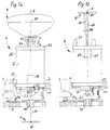
- FIG. 1a shows a centered installation of a geodetic sensor over a defined point.
- a GPS antenna 8 there are a GPS antenna 8, one sensor carrier 4 according to the invention in the carrier position, a tripod 1, parts of a tripod and a floor surface 9 with a floor point 99.
- the bottom part of the GPS antenna 8 has a receiving part, e.g. a Cylinder bore 88 with a locking mechanism (not in Figure 1a shown), whose axis runs through a defined measuring center 89.
- the sensor carrier 4 essentially has, for example cylindrical housing 5 with a side surface 55, the contour of Depressions, e.g. with grip grooves for the fingers, for a safer Handling of the sensor carrier 4 can be determined.
- a first one Centering flange 2 and a substantially the same dimensioned, the same design second centering flange 22 form the two cover surfaces of the housing 5.
- the two centering flanges 2, 22 rigidly connected to the housing 5.
- This optical device can be used with a telescope Graticule (for optical solders) or, as schematically in Figure 1a shown to be a laser collimator 67. This projects a visible one Beams 66 with an optical axis 6 through a window (in FIG 1a not shown) in the center of the first centering flange 2.
- a the Housing 5 facing away from the first centering flange 2 is also perpendicular to the optical axis 6 and has three of them and equally spaced from the optical axis 6 Locking elements 23 on.
- the axes of the enclosing cylinders of the Side faces of the first centering flange 2 and the second Centering flange 22 and the optical axis 6 are coaxial.
- the one Housing 5 facing away from the top surface of the second centering flange 22 perpendicular to the optical axis 6 and has a receiving part for the sensor, e.g. a substantially cylindrical stud 24, whose axis runs coaxially to the extension of the optical axis 6.
- the top surface of the Stud 24 is spaced asz from the top surface of the second Centering flange 22.
- the tripod 1 is by means of three adjusting screws 17a, 17b, 17c, of which only one is shown in FIG. 1a (all three are shown in 2a, 2b, 2c), attached to the tripod plate 19. On Turning the adjusting screws 17a, 17b, 17c causes the tripod 1 to tilt relative to the tripod plate.
- the tripod 1 has on the top an essentially cylindrical receiving bore 11.
- the footprint the receiving bore 11 has a concentric central bore 14 also three from each other and to the axis of the receiving bore 11 each equally spaced openings 13.
- the base area shows also three flat cams 12 (only one shown in Figure 1a), which each next to the openings 13 in a common plane perpendicular to Axis of the receiving bore 11.
- the tilt of this plane relative to A horizontal plane defines both tilt angles of the tripod 1
- Floor surface 9 is a tripod, of which only a part of the Tripod plate 7 and the tightening screw 77 is shown. This one continuous, central hole.
- the first is in the carrier position Centering flange 2 inserted into the receiving bore 11. Because the side surface of the first centering flange 2 and the inner surface of the receiving bore 11 centering and fit the top surface of the first Centering flange 2 rests on the three flat cams 12, the optical falls Axis 6 together with the axis of the receiving bore 11.
- the three Locking elements 23 engage through the three openings 13 and can with a locking mechanism attached to the tripod 1 (in 1a not shown) a releasably locking, positive Form a connection.
- the stud 24 is in the cylinder bore 88 to Stop inserted. Since the side surface of the stud 24 and the Centering inside surface of the cylinder bore 88, runs the extension of the optical axis 6 through the defined measuring center 89.
- a locking mechanism attached to the GPS antenna 8 (in the Fig. 1a not shown) enables a detachable connection with the Sensor carrier 4.
- the tripod can be aligned horizontally. This makes the optical axis 6 to a plumb line of the tripod 1, the sensor carrier 4 and the Measuring center 89.
- the beam 66 projects through the central bore the tightening screw 77 through a luminous dot on the bottom surface 9.
- the sensor carrier 4 and the sensor 8 are moved so that the illuminated dot with the Bottom point 99 is brought to congruence.
- the tripod plate 19 is in this position by tightening the tightening screw 77 on the Tripod plate 7 fixed friction.
- the plane that passes through the top edges of the plan cam 12 is given, has a distance ana to the top of the Tightening screw 77 on.
- the tripod 1, the sensor carrier 4 and the GPS antenna 8 are now centered above ground point 99.
- the The GPS antenna now also has horizontal coordinates of the ground point 99 8, which also by means of the tripod 1, the sensor carrier 4th with their locking mechanisms (not shown in Figure 1a) and the Tripods is securely and stably connected to the floor surface 9.
- the correct installation adjustment of the Laser collimators 67 are verified in the following manner. Since the from Laser collimator 67 projected on the bottom surface 9 illuminated dot defined target point, e.g. the ground point 99, already covered , the tripod 1 fixed to the ground point 99 can be unlocked and the sensor carrier 4 can be implemented by 120 °. For a 120 ° transfer the sensor carrier 4 from the receiving bore 11 so far lifted out until the locking elements 23 secure the openings 23 have left. The sensor carrier 4 is then moved through 120 ° optical axis 6 rotated and again in the receiving bore 11 of the Dreifusses 1 inserted.
- Figure 1b shows a centered setup under a defined point as well as a procedure for the verification of the correct installation adjustment of the Laser collimators 67, without unlocking, repositioning by 120 ° and locking of the sensor carrier 4 is necessary.
- a ceiling surface 10 is shown in FIG. 1b with a ridge point 100 and the sensor carrier 4 in accordance with the invention Verification position, the tripod 1 and the parts of the tripod from Fig. 1a to seen.
- the sensor carrier is 4 in a vertical plane by 180 ° in the so-called verification position rotated and with the second centering flange 22 into the receiving bore 11 of the tripod 1 inserted centering.
- the Outside diameter of the stud 24 is significantly smaller than that Inner diameter of the central bore 14 and the distance ana greater than the distance is asc, can be 4 in when inserting sensor carriers Verification in tripods 1 possible collisions between Stud 24 and the tightening screw 77 or tripod 1 avoided become. Since the side surface of the second centering flange 22 and the Centering the inner surface of the receiving bore 11 and the Cover surface of the second centering flange 22 on the three flat cams 12 rests, the optical axis 6 coincides with the axis of the receiving bore 11 together. By turning the adjusting screws 17a, 17b, 17c, one on the tripod 1 attached circular bubble 3 (shown in Figures 2a, 2b, 2c) The tripod can be aligned horizontally.
- the beam 66 creates a luminous dot on the ceiling surface 10.
- the tripod plate can face away from the flat top surface of the tripod plate 7 19 and thus the tripod 1 and the sensor carrier 4 so that the luminous point is moved with the defined ridge point 100 is covered.
- the tripod plate 19 is now in this Position by tightening the tightening screw 77 on the tripod plate 7 fixed frictionally.
- the tripod 1 and the sensor carrier 4 are now centered set up under ridge point 100. Now the sensor carrier 4 from the Location hole 11 of the centered and leveled tripod 1 removed, rotated by 180 ° and in the carrier position again in the Tripod 1 inserted and locked.
- the sensor carrier 4 stands for centered recordings of a sensor according to FIG. 1a are available, which then also the horizontal coordinates of the ridge point 100 having.
- the second Centering flange 22 the correct installation adjustment of the laser collimator 67 simply and without a rotatably mounted relative to the laser collimator Centering flange, as known from the prior art, to be verified.
- tripods are generally a circular bubble for leveling them possess a sensor carrier according to the invention in its simplest Execution no dragonflies. Due to the required work area and their compact design, circular bubble levels are generally relatively rough Accuracy resolutions of usually six to eight angular minutes each two millimeters of bubble displacement. Centered lineups with high Accuracies can therefore be achieved with sensor carriers designed in this way do not achieve. Because dragonflies usually ten to twenty times Having accuracy resolution of circular bubble levels can also with them accurate centered lineups are performed.
- FIG. 2a, 2b, 2c locked in a tripod 1 Sensor carrier 45, 46, 47 shown in the invention.
- the tripod 1 has a circular level 3 with a bubble 33.
- the eccentricity of the Dragonfly bubble 33 provides two-dimensional tilt angle information combined and is shown enlarged in Figures 2a, 2b, 2c.
- the Sensor carriers 45, 46, 47 are with the exception of attached tubular spirit levels identical to the sensor carrier 4 from FIG. 1a. These dragonflies are arranged on the cover surfaces of the second centering flange.
- FIG. 2a shows a top view of a sensor carrier 45 locked in the tripod 1, with a bubble level 36c, the level axis 35c advantageously parallel to a normal distance line 16c between the screw axes 15a, 15b a first and second set screw 17a, 17b is aligned and the is placed laterally of the stud 24.
- a first and second set screw 17a, 17b is aligned and the is placed laterally of the stud 24.
- the level axis 35c is aligned parallel to the normal distance line 16c.
- the Sensor carrier 45 unlocked in tripod 1, by 120 °, e.g. against the Clockwise, implemented and locked again.
- the tripod 1 By turning the third Set screw 17c can also the tripod 1 in the direction of Normal distance line 16a can be leveled. Because no relevant There are interdependencies between the two leveling processes, the tripod 1 is thus leveled. Also detects the dragonfly bubble 37c a new unlocking, repositioning by 120 ° in the same direction and If the sensor carrier 45 does not unlock any eccentricity, the correct one is Leveling of the tripod 1, as well as the correct installation adjustment of the Tube level 36c, verified.
- non-rotatable carrier with two Tubular dragonflies is a simpler leveling of the tripod 1 without one Moving the sensor carrier possible.
- FIG. 2b shows a sensor carrier 46 which is locked in the tripod 1 and which only by the additional attachment of a second bubble level 36a from Sensor carrier 45 (in Figure 2a) differs.
- the second dragonfly axis 35a in contrast to the prior art, not perpendicular to the first Dragonfly axis 35c but also advantageously parallel to Normal distance line 16a of two setscrew axes 15b, 15c aligned is a horizontal alignment of the bubble level 36c by rotating the set screw 17a simultaneously with one of them practically independent horizontally aligning the bubble level 36a by rotating the Set screw 17c possible.
- the tripod 1 is level, you can use a Unlock, reposition by 120 ° and lock the sensor carrier 46 the correct installation adjustment of the bubble levels 36a, 36c are verified.
- the vial axes 35a, 35b, 35c are parallel to the normal distance lines 16a, 16b, 16c aligned, the tilt angle information is by the Dragonfly bubbles 37a, 37b, 37c shown in such a way that with the help of graphic Symbols such as arrows 38 applied to the housing 5 against clockwise, a simple instruction for leveling of the tripod 1 is possible. If the adjusting screws 17a, 17b, 17c also arrows 39, so the instructions are still further clarified.
- the bubble bubbles 37a, 37b, 37c have eccentricities in the direction of those set screws 17b, 17c which, due to the mechanical conditions of a tripod 1 by adjusting against clockwise level the tripod 1.
- the Tubular levels 36a, 36b, 36c are arranged around the stud 24 are leveling of the tripod 1 from any position around the tripod possible. For this, e.g. the set screw 17c rotated counterclockwise until the bubble 37b is centered. At the same time, the set screw 17b is turned counterclockwise rotated until the bubble level 37c is also central. Will the Centered bubble level 37a, so all three tubular levels 36a, 36b, 36c a correct installation adjustment.
Landscapes
- Physics & Mathematics (AREA)
- Engineering & Computer Science (AREA)
- General Physics & Mathematics (AREA)
- Radar, Positioning & Navigation (AREA)
- Remote Sensing (AREA)
- Position Fixing By Use Of Radio Waves (AREA)
Abstract
Description
Die Erfindung bezieht sich auf einen Träger für, insbesondere geodätische,
Sensoren nach dem Oberbegriff des Anspruchs 1 bzw. eine Vorrichtung nach
dem Oberbegriff des Anspruchs 8. Solche Sensorträger zeichnen sich
dadurch aus, dass mit ihrer Hilfe eine zentrierte Aufstellung vorgenommen
werden kann.The invention relates to a carrier for, in particular geodetic,
Sensors according to the preamble of
Bei vielen Vermessungsaufgaben ist es notwendig, das definierte Messzentrum verschiedener geodätischer Sensoren, wie z.B. GPS-Antennen, Reflektoren, Zieltafeln, Winkelmesser, Distanzmesser oder Zieloptiken, entlang der Lotlinie durch einen definierten Punkt (Vermarkungspunkt, Basispunkt, oder geodätischer Fixpunkt) stationär zu positionieren. Hierfür muss ein horizontierter Dreifuss zentrisch zur Lotlinie auf einem Stativ fixiert und das definierte Messzentrum des Sensors mittels des Sensorträgers zentrisch und in einem bestimmten vertikalen Abstand zum Dreifuss sicher gehalten werden. Solche Sensorträger weisen beispielsweise neben einem Zentrierflansch, passend in die Aufnahmebohrung des Dreifusses, einem Stehbolzen, passend in die Aufnahmebohrung des Sensor, auch noch am Zentrierflansch angebrachte Verriegelungselemente auf, welche im Zusammenspiel mit einer lösbaren Verriegelungsmechanik des Dreifusses mit diesem eine starre Verbindung ermöglichen.For many surveying tasks, it is necessary to do the defined one Measuring center of various geodetic sensors, e.g. GPS antennas, Reflectors, target plates, protractors, distance meters or target optics, along the plumb line through a defined point (mark point, Base point, or geodetic fixed point). Therefor a horizontal tripod must be fixed on a tripod in the center of the plumb line and the defined measuring center of the sensor by means of the sensor carrier centrically and at a certain vertical distance from the tripod being held. Such sensor carriers have, for example, next to one Centering flange, fits into the mounting hole of the tripod, one Stud bolts, fitting in the mounting hole of the sensor, also on Centering flange attached locking elements, which in Interaction with a releasable locking mechanism of the tripod with allow this a rigid connection.
An der Anzugsschraube, durch welche der Dreifuss auf dem Stativ fixiert wird, befestigte Schnurlote oder Lotstäbe sind bekannte Lösungen für eine zentrierte Aufstellung. Mit optischen Einrichtungen, wie z.B. einem Laserkollimator oder einem Fernrohr mit Fadenkreuz, die den Schnittpunkt deren optischer Achse mit einer Fläche sichtbar machen, lassen sich Aufstellungen mit höheren Zentriergenauigkeiten erzielen, falls diese optische Achse auch mit der Lotlinie durch das Messzentrum des Sensors zusammenfällt. Neben einer geometrisch korrekten Aussenform des Sensorträgers mit der korrekten Form und Lage der Gegenstücke für die oben erwähnten Aufnahmen sind dafür vor allem die korrekt justierten Einbaulagen der optischen Einrichtung und einer Vorrichtung zum Horizontieren des Dreifusses entscheidend. Diese korrekten Einbaujustierungen können durch die im praktischen Einsatz sowie beim Transport auftretenden Vibrationen, Stossbelastungen und Temperaturschwankungen verloren gehen. Die Durchführung zuverlässiger, zentrierter Aufstellungen erfordert daher regelmässige Verifikationen der Einbaujustierungen bei diesen Sensorträgern mit optischen Einrichtungen. Diese Geräte haben sich in der Praxis bewährt und werden in verschiedenen Varianten für zentrierte Aufstellungen von Sensoren eingesetzt.On the tightening screw that fixes the tripod to the tripod fastened plumb bobs or plumbing rods are known solutions for one centered lineup. With optical devices, e.g. one Laser collimator or a telescope with crosshairs that intersect whose optical axis can be made visible with a surface Achieve positions with higher centering accuracies, if these optical axis also with the plumb line through the measuring center of the sensor coincides. In addition to a geometrically correct external shape of the Sensor carrier with the correct shape and position of the counterparts for the Above all, the recordings mentioned above are the correctly adjusted ones Installation positions of the optical device and a device for Leveling the tripod is crucial. This correct Installation adjustments can be made by the in practical use as well as Vibrations, shock loads and Temperature fluctuations are lost. Performing reliable, centered lineups therefore requires regular verification of the Installation adjustments for these sensor carriers with optical devices. These devices have proven themselves in practice and are available in different Variants used for centered installation of sensors.
Mit Hilfe autonomer Spezialgeräte, sogenannter Nadir- oder Zenitlote, die neben der optischen Einrichtung in der Regel auch eine hochauflösende Röhrenlibelle aufweisen, kann ein Dreifuss auf einem Stativ horizontiert und flexibel über oder unter einem definierten Punkt zentriert aufgestellt werden. Das Spezialgerät wird dann mit einem Träger ausgetauscht, auf welchem der Sensor zentriert befestigt wird. Dieses Vorgehen wird vor allem bei zentrierten Aufstellungen unter definierten Punkten, sogenannten Firstpunkten, angewendet. Für das zentrierte Aufstellen von Sensoren über einem Bodenpunkt ist dieses Vorgehen im Vergleich zu den vorhandenen Alternativen umständlich und daher nicht üblich.With the help of autonomous special devices, so-called nadir or zenith solders, the in addition to the optical device, usually also a high-resolution one Have a bubble level, a tripod can be leveled on a tripod and can be flexibly centered above or below a defined point. The special device is then exchanged with a carrier on which the Sensor is attached centered. This procedure is mainly used for centered lineups under defined points, so-called Ridge points, applied. For the centered installation of sensors above This approach is a bottom point in comparison to the existing ones Alternatives awkward and therefore not common.
Wird die optische Einrichtung in einem Dreifuss integriert, so sind zentrierte Aufstellungen über einem Bodenpunkt auch ohne spezielle Lotgeräte möglich. Die für die geforderte Zuverlässigkeit geodätischer Anwendungen notwendige regelmässige Verifikation der korrekten Einbaujustierung der optischen Einrichtung des Dreifusses ist aber bei solchen Dreifüssen umständlich und erfordert ein Spezialwerkzeug, mit dem es möglich ist, den Dreifuss um die Achse seiner Aufnahmebohrung zu drehen und zwischen den Drehungen den Schnittpunkt der optischen Achse mit einer Fläche zu beobachten.If the optical device is integrated in a tripod, there are centered ones Installation above a floor point without special soldering equipment possible. The required for the reliability of geodetic applications necessary regular verification of the correct installation adjustment of the Optical setup of the tripod is with such tripods cumbersome and requires a special tool with which it is possible Tripod around the axis of its location hole and between the Rotations to the intersection of the optical axis with a surface observe.
Eine weitere Variante ist die Integration der optischen Einrichtung im Sensorträger. Da bei dieser Variante der Zentrierflansch relativ zu den anderen Teilen des Sensorträgers drehbar gelagert ist, spricht man bei dieser Variante von drehbaren Sensorträgern. Durch Drehen des Sensorträgers und Beobachten des Schnittpunktes der optischen Achse mit einer Fläche ist eine einfache Verifizierung der Einbaujustierung in einem aufgestellten Dreifuss möglich. In der Regel weist ein drehbarer Sensorträger für die Durchführung genauer Zentrierungen eine Röhrenlibelle mit hoher Genauigkeitsauflösung auf. Da auch sie relativ zum Zentrierflansch drehbar gelagert ist, kann durch eine ebene Drehung des Sensorträgers um 180° ihre Einbaujustierung verifiziert werden. Die Anforderungen geodätischer Anwendungen bezüglich Genauigkeit und Stabilität erfordern aber eine entsprechend aufwendige Gestaltung und Herstellung drehbarer Sensorträger. Zudem beeinträchtigen mögliche Verschmutzungen der sich gegeneinander bewegenden Gleitlagerflächen des Zentrierflansches und des Gehäuses des Sensorträgers die gewünschte Wartungsfreiheit sowie die erzielbare Zentriergenauigkeit drehbarer Sensorträger. Das Horizontieren eines Dreifusses durch einen solchen Sensorträger mit nur einer Röhrenlibelle erfordert zudem mehrere Arbeitsschritte, zwischen denen der Sensorträger zweckmässigerweise um möglichst genau 90° gedreht werden sollte.Another variant is the integration of the optical device in the Sensor support. Because in this variant the centering flange is relative to the other parts of the sensor carrier is rotatably supported, one speaks in this Variant of rotatable sensor carriers. By turning the sensor carrier and Observing the intersection of the optical axis with a surface is one simple verification of the installation adjustment in a set up tripod possible. As a rule, a rotatable sensor carrier for the implementation precise centering of a tubular spirit level with high accuracy resolution on. Since it is also rotatably mounted relative to the centering flange, can a level rotation of the sensor carrier by 180 ° their installation adjustment be verified. The requirements of geodetic applications regarding Accuracy and stability require a correspondingly complex Design and manufacture of rotatable sensor carriers. Also affect possible contamination of the moving against each other Plain bearing surfaces of the centering flange and the housing of the sensor carrier the desired freedom from maintenance and the achievable centering accuracy rotatable sensor carrier. Leveling a tripod by one such a sensor carrier with only one vial also requires several Steps between which the sensor carrier expediently around should be turned as exactly 90 ° as possible.
Die Aufgabe der Erfindung besteht darin, einen eingangs genannten Sensorträger anzugeben, der einfache zentrierte Aufstellungen über oder unter definierten Punkten ermöglicht, welcher trotz seiner einfachen Konstruktion eine einfache Verifikation der Einbaujustierung seiner optischen Einrichtung sowie seiner allenfalls aufweisenden Röhrenlibellen ermöglicht.The object of the invention is one mentioned at the outset Specify sensor carrier, the simple centered lineups over or under defined points, which despite its simple Construction a simple verification of the installation adjustment of its optical Facility as well as its possibly existing tube levels.
Diese Aufgabe wird durch die Verwirklichung der kennzeichnenden Merkmale
der Ansprüche 1 bzw. 8 gelöst. This task is accomplished by realizing the characteristic features
of
Vorteilhafte bzw. alternative Lösungen sind in den Kennzeichen der abhängigen Ansprüche beschrieben.Advantageous or alternative solutions are in the characteristics of the dependent claims described.
Bei einem erfindungsgemässen Sensorträger werden bzw. sind grundsätzlich alle für die Durchführung einer zentrierten Aufstellung in einer Aufnahmebohrung eines Dreifusses relevanten Bauteile, wie z.B. die optische Einrichtung zum Sichtbarmachen eines Geradenschnittpunktes, das Gegenstück für das Aufnahmeelement des Dreifusses und gegebenenfalls die Gravitationssensoren, starr miteinander verbunden, was neben den Herstellkosten, das Gewicht und die Anzahl der Teile reduziert und zudem die Robustheit steigert. Als starr verbunden bzw. verbindbar im Sinne der vorliegenden Erfindung soll verstanden werden, dass ein Lösen bzw. Herstellen einer derartigen starren Verbindung nicht selbsttätig, oder beim normalen Gebrauch erfolgen kann. Eine Verifikation der korrekten Einbaujustierung der optischen Einrichtung ist wie bei einem aus dem Stand der Technik bekannten, drehbaren Träger im Feldeinsatz auch ohne Spezialwerkzeug möglich.In the case of a sensor carrier according to the invention, are or are in principle all for performing a centered setup in one Location hole of a tripod relevant components, e.g. the optical Device for making a line intersection visible, the Counterpart for the receiving element of the tripod and, if applicable, the Gravity sensors, rigidly connected to what is next to the Manufacturing costs, the weight and the number of parts reduced and also the robustness increases. As rigidly connected or connectable in the sense of the present invention is to be understood that a loosening or Establish such a rigid connection not automatically, or when normal use. A verification of the correct one Installation adjustment of the optical device is like one from a standing start the known, rotatable carrier in the field even without Special tools possible.
Das Aufnahmeelement des Dreifusses sowie das entsprechende Gegenstück des Sensorträgers müssen aber nicht zwangsläufig eine zylindrische Form aufweisen. Grundsätzlich sind dafür neben beispielsweise quaderförmigen Formen auch Geometrien denkbar, welche es erlauben, den Sensorträger um eine durch ihn selbst verlaufende Achse gedreht in wenigstens zwei im wesentlichen eindeutig bestimmte Stellungen in bezug auf die und auf der Plattform festzustellen.The tripod mounting element and the corresponding counterpart of the sensor carrier do not necessarily have to be cylindrical exhibit. Basically, in addition to, for example, cuboid Shapes are also conceivable, which allow the sensor carrier to be changed an axis running through itself rotated in at least two in essentially clearly defined positions in relation to and on the Platform.
Eine als Gegenstück für das Aufnahmeelement der Plattform wirkende, erste Deckfläche und eine zweite, zur ersten parallel ausgerichtete Deckfläche müssen nicht zwangsläufig geschlossene, zusammenhängende oder ebene Flächen sein. Für eine erfindungsgemässe Funktion des Sensorträgers genügt es, dass die Deckflächen so gestaltet sind, dass Teile der Deckflächen mit der Oberfläche des Aufnahmeelementes der Plattform so zusammenwirken, dass der Sensorträger in jeder Stellung mit der Plattform zusammengefügt immer die gleiche durch ihn selbst verlaufende Achse aufweist.One, which acts as a counterpart for the receiving element of the platform Top surface and a second top surface aligned parallel to the first do not necessarily have to be closed, coherent or level Surfaces. It is sufficient for a function of the sensor carrier according to the invention it that the cover surfaces are designed so that parts of the cover surfaces with the surface of the receiving element of the platform interact so that the sensor carrier is joined to the platform in every position always has the same axis running through it.
Sind in der Seitenfläche eines im wesentlichen zylindrischen Sensorträgers Vertiefungen oder Einbuchtungen vorgesehen, z.B. Griffrillen für die Finger oder eine Griffmulde für die Hand, so wird die Handhabung des Trägers sicherer und auch mit Handschuhen durchführbar.Are in the side surface of a substantially cylindrical sensor carrier Indentations or indentations are provided, e.g. Grip grooves for the fingers or a recessed grip for the hand, so the handling of the carrier safer and can also be carried out with gloves.
Unter Raumdecken, Vordächern, aufgeklappten Kofferraumdeckeln oder Fahrzeughimmeln sind Verifikationen der korrekten Einbaujustierung mit ungedrehten, in der Aufnahmebohrung eines Dreifusses drehenden, erfindungsgemässen Sensorträgern komfortabel möglich.Under ceilings, canopies, opened trunk lids or Vehicle headliners are verifications of the correct installation adjustment with unturned, rotating in the mounting hole of a tripod, sensor carriers according to the invention are conveniently possible.
Da das Strahlbündel der optischen Einrichtung bei einem erfindungsgemässen Sensorträger in Verifikationsstellung nach oben zeigt, besitzt er dadurch auch die Funktionalität eines Zenitlotes. Zentrierte Aufstellungen unter einem Firstpunkt können daher auch ohne ein autonomes Zenitlotgerät vorgenommen werden.Since the beam of the optical device at one shows the sensor carrier according to the invention in the verification position upwards, it also has the functionality of a zenith solder. centered Lineups under a ridge point can therefore also be made without one autonomous zenith soldering device can be made.
Für Horizontierungen mit beschränkten Genauigkeiten braucht der erfindungsgemässe Träger keinen eigenen Gravitationssensor aufzuweisen. In dieser einfachsten Ausführung eines erfindungsgemässen Sensorträgers wird auf die Horizontierungsinformation der an Dreifüssen vorhandenen Dosenlibelle zurückgegriffen, was zusätzlich Herstellkosten spart.For leveling with limited accuracy, the Carrier according to the invention does not have its own gravity sensor. In this simplest embodiment of a sensor carrier according to the invention is based on the leveling information available on tripods Circular bubble level used, which also saves manufacturing costs.
Für zentrierte Aufstellungen mit hohen Genauigkeiten kann eine Vorrichtung mit wenigstens einer Röhrenlibelle eingesetzt werden, welche erfindungsgemäss parallel zu jeweils einer und nur einer durch die wenigstens drei Stellschraubenachsen eines Dreifusses aufgespannten Ebenen ausgerichtet ist. Je nach Anzahl der eingesetzten Röhrenlibellen kann der Komfort und die Schnelligkeit von Horizontierungen von Dreifüssen - mit gegebenenfalls darin verriegelten Sensorträgern - gegenüber dem Stand der Technik erheblich gesteigert werden, da das für eine Horizontierung notwendige, aus dem Stand der Technik bekannte, mehrmalige, möglichst genaue Ausrichten der Röhrenlibelle relativ zu den Stellschrauben eines Dreifusses nicht mehr notwendig ist. Auch eine einfache Verifikation der korrekten Einbaujustierung der Röhrenlibellen ist im Feldeinsatz möglich.A device can be used for centered setups with high accuracy can be used with at least one bubble level, which According to the invention parallel to one and only one through the at least three set screw axes of a tripod Levels. Depending on the number of tubular vials used the comfort and speed of tripod leveling - with if necessary, locked sensor carriers - compared to the state of the Technology can be increased significantly because that is for a leveling necessary, known from the prior art, multiple times, if possible exact alignment of the bubble level relative to the set screws Tripod is no longer necessary. Also a simple verification of the Correct installation adjustment of the bubble levels is possible in the field.
Weist eine solche Vorrichtung zwei erfindungsgemäss angeordnete Röhrenlibellen auf, kann das für eine Horizontierung notwendige, aus dem Stand der Technik bekannte, mehrmalige alternierende Drehen von Stellschrauben und gegebenenfalls des Sensorträgers durch ein zweimaliges, voneinander unabhängiges Drehen einer jeweils einer Röhrenlibelle zugeordneten Stellschraube ersetzt werden. Dies ermöglicht ein paralleles zielgerichtetes Drehen der Stellschrauben.Such a device has two arranged according to the invention Tubular dragonflies, can be used for leveling, from which State of the art, repeated alternating turning of Set screws and, if necessary, the sensor carrier by a double, mutually independent turning of a tubular spirit level assigned screw are replaced. This enables a parallel targeted turning of the set screws.
Weist eine solche Vorrichtung drei erfindungsgemäss angeordnete Röhrenlibellen auf, so ist jede durchgeführte gemeinsame Horizontierung zugleich auch eine Verifikation der korrekten Einbaujustierung der drei Röhrenlibellen. Da bei einer entsprechenden Bauausführung jeweils zwei Libellenblasen aus jeder Position rings um die Vorrichtung eingesehen werden können, kann die Horizontierung auch aus vielen Positionen rings um die Vorrichtung vorgenommen werden, ohne die Vorrichtung - wie beispielsweise bei einer drehbar gelagerten Röhrenlibelle - zuerst in die richtige Ausgangslage drehen zu müssen.Such a device has three arranged according to the invention On each level, this is every leveling at the same time a verification of the correct installation adjustment of the three Bubble levels. Because with a corresponding construction, two Bubble bubbles viewed from every position around the device can be leveled from many positions around the device can be made without the device - like For example, with a rotatable bubble level - first in the to have to turn the correct starting position.
Da ein Dreifuss drei miteinander gekoppelte, zueinander nicht rechtwinklige Kippachsen aufweist, kann ein gezieltes Drehen der Stellschrauben für eine Horizontierung, basierend auf der kombiniert dargestellten, zweidimensionalen Horizontierungsinformation einer Dosenlibelle, für wenig geübte Anwender geodätischer Instrumente, z.B. Geologen, Archäologen, Forstingenieure und viele Anwender im Bauwesen, nicht offensichtlich sein. Durch die erfindungsgemässe Anordnung dreier Röhrenlibellen ist die Horizontierungsinformation so dargestellt, dass mit Hilfe von graphischen Symbolen einfache Handlungsanweisungen möglich werden, die es auch wenig geübten Anwendern erlauben, durch gezieltes Drehen der Stellschrauben Dreifüsse zu horizontieren. Weist ein Dreifuss relativ zu einer Horizontalebene grössere Kippwinkel auf, so befindet sich die Dosenlibelle ausserhalb ihres Arbeitsbereiches und kann nicht mehr auf Drehungen der Stellschrauben reagieren. Ohne eine Handlungsanweisung kann ein Drehen der Stellschrauben in die falsche Richtung vor allem von ungeübten Anwendern nicht gleich erkannt werden.Because a tripod is three coupled, not perpendicular to each other Tilting axes can be a targeted turning of the screws for a Leveling, based on the combined, two-dimensional leveling information of a circular bubble, for little experienced users of geodetic instruments, e.g. Geologists, archaeologists, Forest engineers and many construction users, may not be obvious. Due to the arrangement of three tubular vials according to the invention Leveling information displayed in such a way that with the help of graphic Symbols simple instructions for action are possible, which it too allow inexperienced users by turning the Set screws to level tripods. Has a tripod relative to one The larger level is at the horizontal level, so the circular level is located outside their work area and can no longer turn on the Set screws react. Without instructions, turning can happen the set screws in the wrong direction especially from inexperienced Users are not recognized immediately.
Es ist einsichtig, dass anstelle von Röhrenlibellen auch andere Anzeigemittel vorgesehen werden können, welche die Horizontierungsinformation von Plattformen mit mehr als zwei Kippachsen, wie z.B. geodätische Dreifüsse, in einer erfindungsgemässen Art und Weise darstellen. Bei einem Sensorträger mit elektronischem Gravitationssensor und graphikfähigem Display, wie z.B. einem Tachymeter, wäre es durchaus denkbar, dem Anwender die Horizontierungsinformation mittels der für eine Horizontierung notwendigen Drehungen, z.B. unter Angabe des Drehungwinkelwertes sowie der Drehrichtung, den jeweils betreffenden Stellmitteln zugeordnet, zur Verfügung zu stellen. Die erfindungsgemässe Art und Weise der Darstellung der Horizontierungsinformation ist nicht auf Plattformen von Sensorträgern beschränkt, sondern grundsätzlich bei allen auf mehreren Stellmitteln ruhenden Gegenständen denkbar, die mit diesen Stellmitteln horizontal ausrichtbar sind.It is obvious that instead of tubular spirit levels, other display means can be provided which the leveling information of Platforms with more than two tilt axes, e.g. geodesic tripods, represent in a manner according to the invention. At a Sensor carrier with electronic gravity sensor and graphic capable Display, e.g. a tachymeter, it would be quite conceivable that Users use the leveling information for a leveling necessary rotations, e.g. stating the angle of rotation value as well the direction of rotation, assigned to the respective actuating means, for To make available. The manner of representation according to the invention The leveling information is not on sensor carrier platforms limited, but basically for all on several adjusting devices stationary objects conceivable with these adjusting devices horizontally can be aligned.
Die geometrischen Gegebenheiten einer erfindungsgemässen Anordnung - gegenüber einer dem Stand der Technik entsprechenden rechtwinkligen Anordnung der Röhrenlibellen - ermöglicht entweder eine grössere Libellenlänge, mit dem Vorteil einer besseren Genauigkeitsauflösung bei gleichbleibendem Arbeitsbereich, oder erlaubt konstruktiv einfachere Lösungen, da mehr Raum für Einbaujustiervorrichtungen der Röhrenlibellen vorhanden ist. The geometrical conditions of an arrangement according to the invention - compared to a right angle corresponding to the prior art Arrangement of the bubble levels - either allows a larger one Dragonfly length, with the advantage of a better accuracy resolution constant work area, or allows structurally simpler Solutions, as there is more space for built-in adjustment devices for the bubble levels is available.
Nachfolgend wird die Erfindung rein beispielhaft anhand der in der Zeichnung dargestellten Figuren näher erläutert. Es zeigen:
- Figur 1a
- einen erfindungsgemässen Sensorträger in Trägerstellung mit aufgesteckter GPS-Antenne in der Aufnahmebohrung eines im teilweisen Schnitt gezeigten Dreifusses auf einem teilweise dargestellten Stativ über einem Bodenpunkt in Seitenansicht;
- Figur 1b
- den Sensorträger aus Figur 1a in Verifikationsstellung in der Aufnahmebohrung eines im teilweisen Schnitt gezeigten Dreifusses auf einem teilweise dargestellten Stativ unter einem Firstpunkt in Seitenansicht und
- Figur 2a,
- 2b, 2c weitere Sensorträger mit Röhrenlibellen in einem Dreifuss verriegelt in Draufsicht.
- Figure 1a
- a sensor carrier according to the invention in the carrier position with attached GPS antenna in the mounting hole of a tripod shown in partial section on a tripod partially shown above a ground point in side view;
- Figure 1b
- 1a in the verification position in the receiving bore of a tripod shown in partial section on a tripod partially shown under a ridge point in side view and
- Figure 2a,
- 2b, 2c further sensor carriers with tubular spirit levels locked in a tripod in plan view.
Die Figur 1a zeigt eine zentrierte Aufstellung eines geodätischen Sensors
über einem definierten Punkt. Es sind eine GPS-Antenne 8, ein
erfindungsgemässer Sensorträger 4 in Trägerstellung, ein Dreifuss 1, Teile
eines Stativs und eine Bodenfläche 9 mit einem Bodenpunkt 99 dargestellt.
Das Bodenteil der GPS-Antenne 8 weist ein Aufnahmeteil, z.B. eine
Zylinderbohrung 88 mit einem Verriegelungsmechanismus (in Figur 1a nicht
dargestellt) auf, deren Achse durch ein definiertes Messzentrum 89 verläuft.
Der Sensorträger 4 besitzt beispielsweise ein im wesentlichen
zylinderförmiges Gehäuse 5 mit einer Seitenfläche 55, deren Kontur durch
Vertiefungen, z.B. durch Griffrillen für die Finger, für eine sicherere
Handhabung des Sensorträgers 4 bestimmt sein kann. Ein erster
Zentrierflansch 2 und ein im wesentlichen gleichbemasster, gleichgestalteter
zweiter Zentrierflansch 22 bilden die beiden Deckflächen des Gehäuses 5. Im
Gegensatz zu drehbaren Sensorträgern sind die beiden Zentrierflansche 2, 22
starr mit dem Gehäuse 5 verbunden. Im Gehäuse 5 ist eine optische
Einrichtung starr eingebaut. Diese optische Einrichtung kann ein Fernrohr mit
Strichplatte (bei optischen Loten) oder, wie in Figur 1a schematisch
dargestellt, ein Laserkollimator 67 sein. Dieser projiziert ein sichtbares
Strahlenbündel 66 mit einer optischen Achse 6 durch eine Fenster (in Figur
1a nicht dargestellt) im Zentrum des ersten Zentrierflansches 2. Eine dem
Gehäuse 5 abgewandte Deckfläche des ersten Zentrierflansches 2 steht
ebenfalls senkrecht auf die optischen Achse 6 und weist drei voneinander
sowie zur optischen Achse 6 jeweils gleichmässig beabstandete
Verriegelungselemente 23 auf. Die Achsen der umschliessenden Zylinder der
Seitenflächen des ersten Zentrierflansches 2 und des zweiten
Zentrierflansches 22 und die optische Achse 6 sind koaxial. Die dem
Gehäuse 5 abgewandte Deckfläche des zweiten Zentrierflansches 22 steht
senkrecht zur optischen Achse 6 und weist ein Aufnahmeteil für den Sensor,
z.B. einen im wesentlichen zylindrischen Stehbolzen 24, auf, dessen Achse
koaxial zur Verlängerung der optischen Achse 6 verläuft. Die Deckfläche des
Stehbolzens 24 weist einen Abstand asz von der Deckfläche des zweiten
Zentrierflansches 22 auf. Der Dreifuss 1 ist mittels dreier Stellschrauben
17a, 17b, 1 7c von denen in Figur 1a nur eine dargestellt ist (alle drei sind in
den Figuren 2a, 2b, 2c dargestellt), auf der Dreifussplatte 19 befestigt. Ein
Drehen der Stellschrauben 17a, 17b, 17c hat ein Kippen des Dreifusses 1
relativ zur Dreifussplatte zur Folge. Der Dreifuss 1 weist an der Oberseite
eine im wesentliche zylindrische Aufnahmebohrung 11 auf. Die Grundfläche
der Aufnahmebohrung 11 weist neben einer konzentrischen Zentralbohrung
14 auch noch drei voneinander sowie zur Achse der Aufnahmebohrung 11
jeweils gleichmässig beabstandete Öffnungen 13 auf. Die Grundfläche weist
zudem drei plane Nocken 12 (in Figur 1a nur eine dargestellt) auf, welche
jeweils neben den Öffnungen 13 in einer gemeinsamen Ebene senkrecht zur
Achse der Aufnahmebohrung 11 liegen. Die Kippung dieser Ebene relativ zu
einer Horizontalebene definiert beide Kippwinkel des Dreifusses 1. Auf der
Bodenfläche 9 ist ein Stativ aufgestellt, von dem nur ein Teil des
Stativtellers 7 und der Anzugsschraube 77 dargestellt ist. Diese weist eine
durchgehende, zentrale Bohrung auf. In Trägerstellung ist der erste
Zentrierflansch 2 in die Aufnahmebohrung 11 eingefügt. Da die Seitenfläche
des ersten Zentrierflansches 2 und die Innenfläche der Aufnahmebohrung 11
ineinander zentrierend passen und die Deckfläche des ersten
Zentrierflansches 2 auf den drei planen Nocken 12 aufliegt, fällt die optische
Achse 6 mit der Achse der Aufnahmebohrung 11 zusammen. Die drei
Verriegelungselemente 23 greifen durch die drei Öffnungen 13 hindurch und
können mit einem am Dreifuss 1 befestigten Verriegelungsmechanismus (in
der Fig. 1a nicht dargestellt) eine lösbar verriegelnde, formschlüssige
Verbindung bilden. In der Zylinderbohrung 88 ist der Stehbolzen 24 bis zum
Anschlag eingeschoben. Da die Seitenfläche des Stehbolzens 24 und die
Innenfläche der Zylinderbohrung 88 ineinander zentrierend passen, verläuft
die Verlängerung der optischen Achse 6 durch das definierte Messzentrum
89. Ein an der GPS-Antenne 8 befestigter Verriegelungsmechanismus (in der
Fig. 1a nicht dargestellt) ermöglicht eine lösbare Verbindung mit dem
Sensorträger 4. Durch ein entsprechendes Drehen der Stellschrauben 17a,
17b, 17c kann mit Hilfe der Horizontierungsinformation einer am Dreifuss 1
angebrachten Dosenlibelle 3 (in den Figuren 2a, 2b, 2c dargestellt) der
Dreifuss horizontal ausgerichtet werden. Dadurch wird die optische Achse 6
zu einer Lotlinie des Dreifusses 1, des Sensorträgers 4 und des
Messzentrums 89. Das Strahlbündels 66 projiziert durch die zentrale Bohrung
der Anzugsschraube 77 hindurch einen Leuchtpunkt auf die Bodenfläche 9.
Auf der dem Stativ abgewandten, planen Deckfläche des Stativtellers 7 kann
die Dreifussplatte 19 und damit verbunden der Dreifuss 1, der Sensorträger
4 sowie der Sensor 8 so verschoben werden, dass der Leuchtpunkt mit dem
Bodenpunkt 99 zur Deckung gebracht wird. Die Dreifussplatte 19 wird in
dieser Stellung durch ein Anziehen der Anzugsschraube 77 auf dem
Stativteller 7 reibfest fixiert. Die Ebene, welche durch die Oberkanten der
planen Nocken 12 gegeben ist, weist einen Abstand ana zur Oberkante der
Anzugsschraube 77 auf. Der Dreifuss 1, der Sensorträger 4 und die GPS-Antenne
8 sind jetzt zentriert über dem Bodenpunkt 99 aufgestellt. Die
horizontalen Koordinaten des Bodenpunktes 99 weist nun auch die GPS-Antenne
8 auf, welche zudem mittels des Dreifusses 1, des Sensorträgers 4
mit ihren Verriegelungsmechanismen (in Figur 1a nicht dargestellt) und des
Stativs mit der Bodenfläche 9 sicher und stabil verbunden ist. FIG. 1a shows a centered installation of a geodetic sensor
over a defined point. There are a
In der in Fig. 1a gezeigten Anordnung kann die korrekte Einbaujustierung des
Laserkollimators 67 auf folgende Weise verifiziert werden. Da der vom
Laserkollimator 67 auf der Bodenfläche 9 projizierte Leuchtpunkt mit einem
definierten Zielpunkt, z.B. dem Bodenpunkt 99, bereits zur Deckung gebracht
worden ist, kann der zum Bodenpunkt 99 fixierte Dreifuss 1 entriegelt und
der Sensorträger 4 um 120° umgesetzt werden. Für ein Umsetzen um 120°
wird der Sensorträger 4 aus der Aufnahmebohrung 11 soweit
herausgehoben, bis die Verriegelungselemente 23 die Öffnungen 23 sicher
verlassen haben. Anschliessend wird der Sensorträger 4 um 120° um die
optische Achse 6 gedreht und wieder in die Aufnahmebohrung 11 des
Dreifusses 1 hineingeschoben. Die zwei Öffnungen 13, aus denen das
jeweilige Verriegelungselement 23 zuerst herausgehoben und nach dem
Drehen um 120° hineingeschoben wird, sind gegeneinander um 120°
versetzt. Die durch die Öffnungen 13 hindurchgreifenden
Verriegelungselemente 23 ermöglichen erneut im Zusammenspiel mit dem
Verriegelungsmechanismus des Dreifusses eine formschlüssige, verriegelnde
Verbindung. Deckt sich der durch den Laserkollimator 67 projizierte
Leuchtpunkt auch nach dem Umsetzen um 120° mit dem Bodenpunkt 99, so
ist damit die korrekte Einbaujustierung des Laserkollimators 67 verifiziert.In the arrangement shown in Fig. 1a, the correct installation adjustment of the
Die Figur 1b zeigt eine zentrierte Aufstellung unter einem definierten Punkt
sowie ein Vorgehen für die Verifikation der korrekten Einbaujustierung des
Laserkollimators 67, ohne ein Entriegeln, Umsetzen um 120° und Verriegeln
des Sensorträgers 4 notwendig ist. Aus Figur 1b sind eine Deckenfläche 10
mit einem Firstpunkt 100 sowie der erfindungsgemässe Sensorträger 4 in
Verifikationsstellung, der Dreifuss 1 und die Teile des Stativs aus Fig. 1a zu
ersehen. Ausgehend von der Trägerstellung aus Figur 1a ist der Sensorträger
4 in einer Vertikalebene um 180° in die sogenannte Verifikationsstellung
gedreht und mit dem zweiten Zentrierflansch 22 in die Aufnahmebohrung 11
des Dreifusses 1 zentrierend eingefügt. Da bei dieser Ausführungsform der
Aussendurchmesser des Stehbolzens 24 wesentlich kleiner als der
Innendurchmesser der Zentralbohrung 14 und der Abstand ana grösser als
der Abstand asc ist, können beim Einfügen von Sensorträgern 4 in
Verifikationsstellung in Dreifüsse 1 mögliche Kollisionen zwischen
Stehbolzen 24 und der Anzugsschraube 77 oder dem Dreifuss 1 vermieden
werden. Da die Seitenfläche des zweiten Zentrierflansches 22 und die
Innenfläche der Aufnahmebohrung 11 ineinander zentrierend passen und die
Deckfläche des zweiten Zentrierflansches 22 auf den drei planen Nocken 12
aufliegt, fällt die optische Achse 6 mit der Achse der Aufnahmebohrung 11
zusammen. Durch ein entsprechendes Drehen der Stellschrauben 17a, 17b,
17c kann mit Hilfe der Horizontierungsinformation einer am Dreifuss 1
angebrachten Dosenlibelle 3 (in den Figuren 2a, 2b, 2c dargestellt) der
Dreifuss horizontal ausgerichtet werden. Dadurch wird die optische Achse 6
zur Lotlinie des Dreifusses 1 und des Sensorträgers 4. Das Strahlbündel 66
erzeugt einen Leuchtpunkt auf der Deckenfläche 10. Auf der dem Stativ
abgewandten, planen Deckfläche des Stativtellers 7 kann die Dreifussplatte
19 und damit verbunden der Dreifuss 1 und der Sensorträger 4 so
verschoben werden, dass der Leuchtpunkt mit dem definierten Firstpunkt
100 zur Deckung gebracht wird. Die Dreifussplatte 19 wird nun in dieser
Stellung durch ein Anziehen der Anzugsschraube 77 auf dem Stativteller 7
reibfest fixiert. Der Dreifuss 1 und der Sensorträger 4 sind jetzt zentriert
unter dem Firstpunkt 100 aufgestellt. Nun kann der Sensorträger 4 aus der
Aufnahmebohrung 11 des zentrierten und horizontierten Dreifusses 1
herausgenommen, um 180°gedreht und in Trägerstellung wieder in den
Dreifuss 1 eingefügt und verriegelt werden. Der Sensorträger 4 steht für
zentrierte Aufnahmen eines Sensors entsprechend Figur 1a zur Verfügung,
welcher dann ebenfalls die horizontalen Koordinaten des Firstpunktes 100
aufweist.Figure 1b shows a centered setup under a defined point
as well as a procedure for the verification of the correct installation adjustment of the
Wie aus Figur 1 b auch zu ersehen, kann aufgrund des zweiten
Zentrierflansches 22 die korrekte Einbaujustierung des Laserkollimators 67
einfach und ohne einen relativ zum Laserkollimator drehbar gelagerten
Zentrierflansch, wie aus dem Strand der Technik bekannt, verifiziert werden. As can also be seen from FIG. 1 b, the second
Centering
Diese Verifikationen sind für eine zuverlässige Durchführung zentrierter
Aufstellungen regelmässig notwendig. Da der zweite Zentrierflansch 22
keine Verriegelungselemente 23 aufweist, kann der Träger 4 in
Verifikationsstellung in der Aufnahmebohrung 11 um deren Achse gedreht
werden. Da diese Achse bei einer korrekten Einbaujustierung des
Laserkollimators 67 mit der optischen Achse 6 zusammenfällt, dreht sich die
Projektion des Strahlbündels 66 auf der Deckenfläche 10 nicht wahrnehmbar
seine eigene optische Achse 6.These verifications are more centered for reliable execution
Statements necessary regularly. Since the second centering
Ist jedoch, wie in Figur 1b punktstrichliert dargestellt, im Gegensatz dazu ein
Laserkollimator 69 nicht (mehr) korrekt justiert eingebaut, so sendet dieser
ein Strahlbündel 68 aus, das die um einen Winkel sw unkorrekte
Einbaudejustierung aufweist. Die optische Achse des Strahlbündels 68 steht
weder senkrecht auf die Deckflächen der beiden Zentrierflansche 2,22 noch
koaxial zur Achse des Stehbolzens 24. Wird nun der Sensorträger 4 mit dem
dejustiert eingebauten Laserkollimator 69 in der Aufnahmebohrung 11 um
deren Achse gedreht, so bewegt sich die Projektion des Strahlbündels 68 auf
einer geschlossenen Bahn mit einem wahrnehmbaren Durchmesser auf der
Deckenfläche 10. Die unkorrekte Einbaudejustierung des Laserkollimators 69
wird offensichtlich und unkorrekte, zentrierte Aufstellungen können
verhindert werden.In contrast, as shown in dash-dotted lines in FIG. 1b, is a
Da im allgemeinen Dreifüsse eine Dosenlibelle für deren Horizontierung besitzen, benötigt ein erfindungsgemässer Sensorträger in seiner einfachsten Ausführung keine Libellen. Bedingt durch den geforderten Arbeitsbereich und ihre kompakte Bauform, weisen Dosenlibellen im allgemeinen relativ grobe Genauigkeitsauflösungen von üblicherweise sechs bis acht Winkelminuten je zwei Millimeter Blasenverschiebung auf. Zentrierte Aufstellungen mit hohen Genauigkeiten lassen sich deshalb mit derartig gestalteten Sensorträgern nicht erzielen. Da Röhrenlibellen üblicherweise die zehn- bis zwanzigfache Genauigkeitsauflösung von Dosenlibellen besitzen, können mit ihnen auch genaue zentrierte Aufstellungen durchgeführt werden. Since tripods are generally a circular bubble for leveling them possess a sensor carrier according to the invention in its simplest Execution no dragonflies. Due to the required work area and their compact design, circular bubble levels are generally relatively rough Accuracy resolutions of usually six to eight angular minutes each two millimeters of bubble displacement. Centered lineups with high Accuracies can therefore be achieved with sensor carriers designed in this way do not achieve. Because dragonflies usually ten to twenty times Having accuracy resolution of circular bubble levels can also with them accurate centered lineups are performed.
Entsprechend sind in Figur 2a, 2b, 2c in einem Dreifuss 1 verriegelte,
erfindungsgemässe Sensorträger 45, 46, 47 dargestellt. Der Dreifusses 1
weist eine Dosenlibelle 3 mit einer Libellenblase 33 auf. Die Exzentrizität der
Libellenblase 33 stellt eine zweidimensionale Kippwinkelinformation
kombiniert dar und ist in den Figuren 2a, 2b, 2c vergrössert dargestellt. Die
Sensorträger 45, 46, 47 sind bis auf zusätzlich angebrachte Röhrenlibellen
mit dem Sensorträger 4 aus der Figur 1a baugleich. Diese Röhrenlibellen sind
an den Deckflächen des zweiten Zentrierflansches angeordnet.Correspondingly, in FIG. 2a, 2b, 2c locked in a
Figur 2a zeigt einen im Dreifuss 1 verriegelten Sensorträger 45 in Draufsicht,
mit einer Röhrenlibelle 36c, deren Libellenachse 35c vorteilhaft parallel zu
einer Normalabstandslinie 16c zwischen den Schraubenachsen 15a, 15b
einer ersten und zweiten Stellschraube 17a, 17b ausgerichtet ist und die
seitlich des Stehbolzens 24 plaziert ist. Bei den in der Praxis vorkommenden
Kippwinkeln von Dreifüssen 1, hat ein Drehen einer gegenüberliegenden
dritten Stellschraube 17c keine wahrnehmbare Auswirkung auf die
Exzentrizität der Libellenblase 37c der Röhrenlibelle 36c, deren Libellenachse
35c parallel zur Normalabstandslinie 16c ausgerichtet ist. Durch Drehen der
ersten zwei Stellschrauben 17a, 17b kann der Dreifuss in Richtung der
Normalabstandslinie 16c horizontal ausgerichtet werden. Danach wird der
Sensorträger 45 im Dreifuss 1 entriegelt, um 120°, z.B. gegen den
Uhrzeigersinn, umgesetzt und wieder verriegelt. Durch Drehen der dritten
Stellschraube 17c kann der Dreifuss 1 auch noch in Richtung der
Normalabstandslinie 16a horizontiert werden. Da keine relevanten
Interdependenzen zwischen den zwei Horizontiervorgängen vorhanden sind,
ist der Dreifuss 1 damit horizontiert. Weist die Libellenblase 37c auch nach
einem erneuten Entriegeln, Umsetzen um 120° in der gleichen Richtung und
Verriegeln des Sensorträgers 45 keine Exzentrizität auf, so ist die korrekte
Horizontierung des Dreifusses 1, sowie die korrekte Einbaujustierung der
Röhrenlibelle 36c, verifiziert. FIG. 2a shows a top view of a
Mit einem erfindungsgemässen, nicht drehbarem Träger mit zwei
Röhrenlibellen ist eine einfachere Horizontierung des Dreifusses 1, ohne ein
Umsetzen des Sensorträgers möglich.With an inventive, non-rotatable carrier with two
Tubular dragonflies is a simpler leveling of the
Figur 2b zeigt einen im Dreifuss 1 verriegelten Sensorträger 46, der sich nur
durch die zusätzliche Anbringung einer zweiten Röhrenlibelle 36a vom
Sensorträger 45 (in Figur 2a) unterscheidet. Da die zweite Libellenachse 35a
im Gegensatz zum Stand der Technik nicht senkrecht auf die erste
Libellenachse 35c sondern vorteilhaft ebenfalls parallel zur
Normalabstandslinie 16a zweier Stellschraubenachsen 15b, 15c ausgerichtet
ist, ist ein horizontales Ausrichten der Röhrenlibelle 36c durch ein Drehen
der Stellschraube 17a gleichzeitig mit einem davon praktisch unabhängigen
horizontalen Ausrichten der Röhrenlibelle 36a durch ein Drehen der
Stellschraube 17c möglich. Ist der Dreifuss 1 horizontiert, so kann mit einem
Entriegeln, Umsetzen um 120° und Verriegeln des Sensorträgers 46 die
korrekte Einbaujustierung der Röhrenlibellen 36a, 36c verifiziert werden.FIG. 2b shows a
Ist, wie bei einem in Figur 2c im Dreifuss 1 verriegelt gezeigten Sensorträger
47, noch eine dritte Röhrenlibelle 36b - vorteilhaft parallel zu einer dritten
Normalabstandslinie 16b der Schraubenachsen 15a, 15c ausgerichtet -
angebracht, kann auf den separaten Arbeitsschritt für eine Verifizierung der
korrekten Einbaujustierung der drei Röhrenlibellen 36a, 36b, 36c verzichtet
werden. Die zweidimensionale Kippwinkelinformation des Dreifusses 1 wird
durch die drei Röhrenlibellen 36a, 36b, 36c redundant erfasst. Eine
Eliminierung der Exzentrizitäten aller Libellenblasen 37a, 37b, 37c ist
praktisch nur möglich, wenn der Dreifusses 1 horizontal ausgerichtet ist und
alle drei Röhrenlibellen 36a, 36b, 36c eine korrekte Einbaujustierung
aufweisen. Gelingt es, nur zwei Libellen horizontal auszurichten, so muss
eine unkorrekte Einbaudejustierung einer oder mehrerer Libellen vorliegen.
Mit Entriegeln, Umsetzen um 120° und Verriegeln des Sensorträgers 47
kann herausgefunden werden, welche Libellen davon betroffen ist (sind). Der
Sensorträger 47 kann dann unter Verwendung der korrekt eingebauten
Libellen für zentrierte Aufstellungen verwendet werden.Is, as with a sensor carrier shown locked in Figure 3c in
Sind die Libellenachsen 35a, 35b, 35c parallel zu den Normalabstandslinien
16a, 16b, 16c ausgerichtet, so wird die Kippwinkelinformation durch die
Libellenblasen 37a, 37b, 37c so dargestellt, dass mit Hilfe von graphischen
Symbolen, wie z.B. am Gehäuse 5 applizierte Drehrichtungspfeile 38 gegen
den Uhrzeigersinn, eine einfache Handlungsanweisung für die Horizontierung
des Dreifusses 1 möglich wird. Weisen zusätzlich die Stellschrauben 17a,
17b, 17c auch noch Pfeile 39 auf, so wird die Handlungsanweisung noch
weiter verdeutlicht. Die Libellenblasen 37a, 37b, 37c weisen Exzentrizitäten
in Richtung derjenigen Stellschrauben 17b, 17c auf, welche aufgrund der
mechanischen Gegebenheiten eines Dreifusses 1 durch ein Verstellen gegen
den Uhrzeigersinn eine Horizontierung des Dreifusses 1 herbeiführen. Da die
Röhrenlibellen 36a, 36b, 36c rings um den Stehbolzen 24 herum angeordnet
sind, ist ein Horizontieren des Dreifusses 1 aus jeder beliebigen Position rings
um das Stativ möglich. Hierfür wird z.B. die Stellschraube 17c solange
gegen den Uhrzeigersinn gedreht, bis die Libellenblase 37b zentrisch ist.
Parallel dazu wird die Stellschraube 17b solange gegen den Uhrzeigersinn
gedreht, bis auch die Libellenblase 37c zentrisch ist. Wird dabei auch die
Libellenblase 37a zentriert, so weisen alle drei Röhrenlibellen 36a, 36b, 36c
eine korrekte Einbaujustierung auf.The vial axes 35a, 35b, 35c are parallel to the
Claims (10)
Priority Applications (1)
| Application Number | Priority Date | Filing Date | Title |
|---|---|---|---|
| EP00124350A EP1207369A1 (en) | 2000-11-17 | 2000-11-17 | Sensor support for performing centred placement |
Applications Claiming Priority (1)
| Application Number | Priority Date | Filing Date | Title |
|---|---|---|---|
| EP00124350A EP1207369A1 (en) | 2000-11-17 | 2000-11-17 | Sensor support for performing centred placement |
Publications (1)
| Publication Number | Publication Date |
|---|---|
| EP1207369A1 true EP1207369A1 (en) | 2002-05-22 |
Family
ID=8170317
Family Applications (1)
| Application Number | Title | Priority Date | Filing Date |
|---|---|---|---|
| EP00124350A Withdrawn EP1207369A1 (en) | 2000-11-17 | 2000-11-17 | Sensor support for performing centred placement |
Country Status (1)
| Country | Link |
|---|---|
| EP (1) | EP1207369A1 (en) |
Cited By (1)
| Publication number | Priority date | Publication date | Assignee | Title |
|---|---|---|---|---|
| EP3660451A1 (en) | 2018-11-28 | 2020-06-03 | Hexagon Technology Center GmbH | Intelligent stationing module |
Citations (5)
| Publication number | Priority date | Publication date | Assignee | Title |
|---|---|---|---|---|
| DE3317732A1 (en) * | 1982-06-08 | 1983-12-08 | Wild Heerbrugg AG, 9435 Heerbrugg | Tripod for geodetic instruments |
| DE4007245A1 (en) * | 1990-03-08 | 1991-09-12 | Wild Heerbrugg Ag | DEVICE FOR CENTERING A GEODETIC INSTRUMENT OVER A DEFINED GROUND POINT |
| FR2741421A1 (en) * | 1995-11-21 | 1997-05-23 | Rivages Productions | ADJUSTABLE TILT SUPPORT DEVICE, PARTICULARLY FOR CONSERVATION OF ITS HORIZONTALITY |
| JPH09196677A (en) * | 1996-01-16 | 1997-07-31 | Fujita Corp | Centering device for gps antenna |
| JPH10274528A (en) * | 1997-03-31 | 1998-10-13 | Nikon Corp | Plumbing device for surveying |
-
2000
- 2000-11-17 EP EP00124350A patent/EP1207369A1/en not_active Withdrawn
Patent Citations (5)
| Publication number | Priority date | Publication date | Assignee | Title |
|---|---|---|---|---|
| DE3317732A1 (en) * | 1982-06-08 | 1983-12-08 | Wild Heerbrugg AG, 9435 Heerbrugg | Tripod for geodetic instruments |
| DE4007245A1 (en) * | 1990-03-08 | 1991-09-12 | Wild Heerbrugg Ag | DEVICE FOR CENTERING A GEODETIC INSTRUMENT OVER A DEFINED GROUND POINT |
| FR2741421A1 (en) * | 1995-11-21 | 1997-05-23 | Rivages Productions | ADJUSTABLE TILT SUPPORT DEVICE, PARTICULARLY FOR CONSERVATION OF ITS HORIZONTALITY |
| JPH09196677A (en) * | 1996-01-16 | 1997-07-31 | Fujita Corp | Centering device for gps antenna |
| JPH10274528A (en) * | 1997-03-31 | 1998-10-13 | Nikon Corp | Plumbing device for surveying |
Non-Patent Citations (2)
| Title |
|---|
| PATENT ABSTRACTS OF JAPAN vol. 1997, no. 11 28 November 1997 (1997-11-28) * |
| PATENT ABSTRACTS OF JAPAN vol. 1999, no. 01 29 January 1999 (1999-01-29) * |
Cited By (2)
| Publication number | Priority date | Publication date | Assignee | Title |
|---|---|---|---|---|
| EP3660451A1 (en) | 2018-11-28 | 2020-06-03 | Hexagon Technology Center GmbH | Intelligent stationing module |
| US11486704B2 (en) | 2018-11-28 | 2022-11-01 | Hexagon Technology Center Gmbh | Intelligent positioning module |
Similar Documents
| Publication | Publication Date | Title |
|---|---|---|
| DE3838512C1 (en) | ||
| EP3660451B1 (en) | Intelligent stationing module | |
| DE102012011518B3 (en) | Geodetic objective for position determination system to determine position of e.g. landmarks, has interface formed to output signals for determination of spatial orientation of reflector relative to target point in marking direction | |
| DE4007245C2 (en) | Device for centering a geodetic instrument over a defined point on the ground | |
| EP1475607B1 (en) | Method for determining the spatial orientation and position of a reflector rod relative to a measuring point | |
| DE20320216U1 (en) | laser scanner | |
| WO2005012839A1 (en) | Method for checking or calibrating the angle-dependent alignment of a high-precision test-piece | |
| DE3401745A1 (en) | Auxiliary fire control device | |
| EP2037294A2 (en) | Measuring device | |
| EP1367362B1 (en) | Geodetic instrument with multiple beam paths | |
| EP1756515B1 (en) | Marking appliance | |
| EP1371931A1 (en) | Method and device for determining an angular error and use thereof | |
| DE2319984A1 (en) | INCLINATION ADJUSTER | |
| DE19716304C1 (en) | Geodetic device for plumbline, theodolite or tachymeter | |
| EP3236204A2 (en) | Levelable rotation laser and its use for measuring machine tools | |
| DE19800901B4 (en) | Positioning probe for mutual alignment of bodies | |
| WO2006136557A1 (en) | Method for horizontally orienting a measuring instrument, and measuring instrument comprising a device for the horizontal orientation thereof | |
| DE60223777T2 (en) | Device with rotatable platform for carrying and aligning a load | |
| EP1207369A1 (en) | Sensor support for performing centred placement | |
| WO2023016606A1 (en) | Device and method for adjusting an axis | |
| CH674573A5 (en) | ||
| DE2158428C3 (en) | Sighting device | |
| DE4334360A1 (en) | Working top for jaw models | |
| DE3317732C2 (en) | ||
| DE102014010778B4 (en) | Alignment devices for use with a drilling machine guided on a drilling machine stand, use of the alignment devices and method for aligning a drilling machine stand |
Legal Events
| Date | Code | Title | Description |
|---|---|---|---|
| PUAI | Public reference made under article 153(3) epc to a published international application that has entered the european phase |
Free format text: ORIGINAL CODE: 0009012 |
|
| 17P | Request for examination filed |
Effective date: 20010615 |
|
| AX | Request for extension of the european patent |
Free format text: AL;LT;LV;MK;RO;SI |
|
| 17Q | First examination report despatched |
Effective date: 20020925 |
|
| AKX | Designation fees paid | ||
| REG | Reference to a national code |
Ref country code: DE Ref legal event code: 8566 |
|
| STAA | Information on the status of an ep patent application or granted ep patent |
Free format text: STATUS: THE APPLICATION IS DEEMED TO BE WITHDRAWN |
|
| 18D | Application deemed to be withdrawn |
Effective date: 20030206 |