EP1205082B1 - Implementation of call setup procedures with separation of call control and bearer control - Google Patents
Implementation of call setup procedures with separation of call control and bearer control Download PDFInfo
- Publication number
- EP1205082B1 EP1205082B1 EP00949374A EP00949374A EP1205082B1 EP 1205082 B1 EP1205082 B1 EP 1205082B1 EP 00949374 A EP00949374 A EP 00949374A EP 00949374 A EP00949374 A EP 00949374A EP 1205082 B1 EP1205082 B1 EP 1205082B1
- Authority
- EP
- European Patent Office
- Prior art keywords
- call
- media gateway
- control
- switching centre
- gateway
- Prior art date
- Legal status (The legal status is an assumption and is not a legal conclusion. Google has not performed a legal analysis and makes no representation as to the accuracy of the status listed.)
- Expired - Lifetime
Links
Images


Classifications
-
- H—ELECTRICITY
- H04—ELECTRIC COMMUNICATION TECHNIQUE
- H04L—TRANSMISSION OF DIGITAL INFORMATION, e.g. TELEGRAPHIC COMMUNICATION
- H04L65/00—Network arrangements, protocols or services for supporting real-time applications in data packet communication
- H04L65/1066—Session management
- H04L65/1069—Session establishment or de-establishment
-
- H—ELECTRICITY
- H04—ELECTRIC COMMUNICATION TECHNIQUE
- H04W—WIRELESS COMMUNICATION NETWORKS
- H04W76/00—Connection management
- H04W76/10—Connection setup
- H04W76/12—Setup of transport tunnels
-
- H—ELECTRICITY
- H04—ELECTRIC COMMUNICATION TECHNIQUE
- H04L—TRANSMISSION OF DIGITAL INFORMATION, e.g. TELEGRAPHIC COMMUNICATION
- H04L65/00—Network arrangements, protocols or services for supporting real-time applications in data packet communication
- H04L65/10—Architectures or entities
- H04L65/102—Gateways
- H04L65/1023—Media gateways
-
- H—ELECTRICITY
- H04—ELECTRIC COMMUNICATION TECHNIQUE
- H04L—TRANSMISSION OF DIGITAL INFORMATION, e.g. TELEGRAPHIC COMMUNICATION
- H04L65/00—Network arrangements, protocols or services for supporting real-time applications in data packet communication
- H04L65/10—Architectures or entities
- H04L65/102—Gateways
- H04L65/1033—Signalling gateways
Definitions
- a conventional GSM (Global System for Mobile Communications) or UMTS (Universal Mobile Telecommunications Service) core network uses bearer control and call control.
- the bearer control is the aspect of signaling related to the control of the selection of a path through the transmission network and utilizing (reserving, releasing and setting up) the required resources.
- the call control is the aspect of signaling related to the subscriber and service control, taking, e. g., the subscriber state into consideration.
- N-ISDN Integrated Services Digital Network
- the call control and the bearer control are integral with one another.
- a user plane is associated directly with the control servers, such as MSCs( Mobile Services switching Centers) and GMSCs (Gateway MSCs).
- MSCs Mobile Services switching Centers
- GMSCs Gateway MSCs
- the control nodes implement both, application logic for signaling and the user plane.
- Knight R. R. and Law B. describe in "The call control protocol in a separated call and bearer environment", published in BT Technical Journal, volume 16 Number 2 published April 1998, a system and a protocol with separated call and bearer control.
- the described system does not separate the control nodes from nodes for the transmission of payload.
- the control nodes perform both, call control and bearer control, separated only in time. By that, optimised routing of payload is not possible.
- the present invention is directed to separation of the call control and the bearer control.
- TFO tandem free operation
- TrFO transcoder free operation
- the application software is independent from the used transmission technology, e. g. STM, ATM, IP.
- TSC server giving a MSC, TSC server the possibility to control several media gateways by allocating one PC per media gateway in the control node.
- the user plane routing for call set-up is optimized significantly.
- the user plane routing for supplementary services CFNREA, CFB, CFNRY, CFU is optimized significantly.
- the user plane routing for supplementary services CW, HOLD is optimized significantly.
- the user plane pipe size is optimized by transferring coded (compressed) user plane to the edge of the network or between two MGWs, e. g. for MPTY calls
- the present invention relates to enabling and optimizing call set-up in a telecommunication network with separated call control and bearer control, i.e., set up of a payload connection.
- the separation of call control and payload transmission means that the signaling between control nodes like MSCs, GMSCs and TSCs takes a different way through the network than the payload. This enables the telecommunication network to perform an optimal routing for the payload, using a minimum of resources.
- originating call, terminating call, internal call or transit call there are only one or maximally two media gateway necessary.
- the invention particularly relates to a method comprising the transmission of an identification of a selected media gateway in a forward direction. That is, the first control node or the second control node selects the media gateway depending on:
- the invention herein relates to implementation of basic call setup, GSM/UMTS supplementary services CFU, CFB, CFNREA, CFNRY, CW, HOLD and MPTY with transporting a media gateway address, a logical point, the chosen coding type and the chosen framing type in a forward direction in networks with separation of call control and bearer control.
- Call set-up is described in various traffic cases, each illustrated in one of the figures.
- Each of the figures is a block diagram of a wireless communication system, such as a GSM or UMTS core network, with directional arrows illustrating control signaling between control servers and with MGWs during call set-up for the different traffic cases.
- the written description herein describes information conveyed in each signal. The particular signal is identified herein and in the drawing with a reference numeral.
- UE User Equipment
- RNC Radio Network Controller
- RRC Radio Resource Control
- a logical point is a reference locally generated by a media gateway and only with the media gateway address valid to identify a connection in the control servers e. g. MSC/VLR (MSC/Visitor Location Register), GMSC, TSC and in the RNC.
- MSC/VLR MSC/Visitor Location Register
- GMSC GMSC
- TSC TSC
- RNC Radio Network Controller
- a logical point P in a first MGW1 is reserved. This reserved point is sent back in a DCP resource response message to the control server and passed on from this control server to another media gateway MGW2 or RNC, which shall set up an AAL2 connection.
- the logical point P is included to identify to which reserved resource in a MGW1 the connection shall be set up.
- the logical point is equivalent to a termination used in the H.GCP protocol standardized by ITU.
- a control node such as one of the control servers, discussed above, provides the application logic.
- the strict separation of the application logic from the user plane handling allows intensive application development and execution.
- the control nodes GMSC, MSC, TSC and home location register HLR (only signaling) exist.
- the interfaces of the control nodes are, e.g., N-ISUP, for call control signaling, DCP signaling for media gateway control and MAP for transferring connectionless signaling between control servers.
- a media gateway modifies or switches the user plane. It performs operations such as announcement generation, tone generation, echo cancellation, modem handling for data calls, frame handling and CODEC (transcoder) handling for speech calls.
- a signaling gateway performs bearer conversion of signaling messages.
- UMTS with an ATM core network and ISDN network interworking a conversion from ATM/AAL5 to MTP is done in the signaling gateway.
- the signaling GW relays the N-ISUP signaling and exchanges the lower transport layer which is carrying the signaling. Therefore the signaling GW is always collocated with e.g. a GMSC or TSC server.
- the backbone network transfers the user plane and the control signaling and can, e.g., be based on STM, ATM or IP.
- the media gateway is the edge node of the backbone network.
- N-ISDN is used for call control
- STM, AAL2 or IP are used for bearer control and usage of the user plane.
- control tones are omitted in this description and shall be handled in other known manners.
- the media gateway address can be transported on BICC, ISDN e. g., as a sublayer transport address.
- the routing analyse or the B-number analyse are used.
- the TSC is then chosen for an outgoing call to the ISDN.
- the media gateway is chosen based on capabilities required for handling the call, e. g. which devices such as CODECs, coding, compression, framing scheme, announcement machines, tone senders, or modems are required. In the examples, for simplification, only the B-number analyse is mentioned. The selection depends mainly on the destination. Depending on the destination a group of MGWs with different capabilities can be found. Then a media gateway with the needed capabilities, e.g. CCDs, modem support, Internet connectivity is chosen.
- the GMSC needs to have one point code per MGW, where the ISDN user plane can terminate. Out of the DPC, to which the IAM was sent, the GMSC can derive the media gateway to which the ISDN user plane was set up.
- IAM control signaling
- the TSC needs one point code per controlled media gateway.
- the TSC has to use a certain OPC.
- the transit switch can distinguish the ISDN user planes received from different MGWs.
- Another alternative solution to receive or send user plane to different MGWs is that different signaling routes are used between servers, if the user plane is routed via different MGWs.
- a third alternative to receive or send user plane to different MGWs from/to a transit switch and control signaling from/to one server is that different CICs are used for different MGWs, if the user plane is routed via different MGWs.
- the concept of identifying the originating media gateway by OPC used in the IAM message instead of transporting the media gateway address in the IAM message, is also possible through the whole CN, but it requires, for a network of m MGWs, m different point codes in each of the the control servers, which can control the MGWs.
- Another alternative solution to transfer the knowledge of an media gateway from one server to the other is to use different routes for signaling, if the user plane was routed to different MGWs. If a TSC can receive calls from m MGWs, then m different signaling routes towards the RNC are required.
- the DTAP messages are defined in GSM 04.08 V8.0.0 and UMTS 24.08 V3.0.0.
- the RANAP messages are defined in UMTS 25.413 V1.0.2.
- the MAP messages are defined in GSM 09.02 V 6.3.0 and UMTS 29.002 V 3.3.2.
- the AAL2 messages are used for bearer control in accordance with the invention.
- the DCP messages which are particularly described below, are used for communications between control nodes and the MGWs in connection with resource requests and assignments.
- the ISDN messages are used for signaling between network control nodes and external ISDN networks. An updated ISDN set of messages is to be used between core network servers. Updated is, for example, the IAM message.
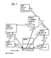
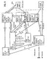
- Figure 1 shows a call from one UE to another UE within the network, with an media gateway address being transported in a forward direction.
- the originating exchange selects the media gateway MGW1, e. g. on traffic and because of location, and transports the media gateway MGW1 address in the forward direction with the ISUP IAM message to the gateway mobile services switching centre GMSC1 and then to the mobile services switching centre MSC2.
- a transcoder is linked in by the originating MSC as the termination is not known.
- the coding negotiated with the user equipment UE1 is used and on the outgoing side a default coding is used.
- the terminating mobile services switching centre mobile services switching centre MSC2 chooses the default coding on the one side and the coding, which it negotiated with the user equipment UE2 on the side of the radio network controller RNC2.
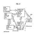
- Figure 2 illustrates a call to UE originating outside of the network.
- the media gateway address is again transported in the forward direction.
- a subscriber is calling a served user equipment UE1.
- only one media gateway is used, which can be used by all control servers to influence the user plane.
- a transcoder is linked in by the terminating mobile services switching centre MSC.
- the terminating mobile services switching centre MSC On the incoming side, e. g. PCM coding is used and on the outgoing side the coding, negotiated with the user equipment UE1 by the radio network controller RNC, is used.
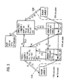
- Figure 3 shows a call forwarding in a GMSC to an ISDN subscriber identified by an ISDN no. outside of the network.
- the media gateway address is transported in the forward direction.
- GMSC can control the set-up as the analyse performed in GMSC
- transit switching centre TSC2 can also deliver the media gateway MGW2 address as a one-to-one relation exists between both.
- a transcoder is optionally linked in by the transit switching centre TSC2 in both media gateways, media gateway MGW1 and media gateway MGW2 to compress the transferred user data.
- TSC2 transit switching centre
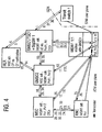
- Figure 4 illustrates call forwarding in GMSC to a UE subscriber identified by a UE no. in the network.
- the media gateway address is transported in the forward direction.
- GMSC2 For subsequent forwarding to UE in GMSC instead of gateway mobile services switching centre GMSC2 several GMSCs have to be included. In this case only one media gateway is used, which can be used by all control servers to influence the user plane.
- a transcoder is linked in by the terminating mobile services switching centre MSC. On the incoming side, e. g. PCM coding is used and on the outgoing side the coding, negotiated with the user equipment UE1, is used.
- Figure 5 illustrates a call from UE with Call forwarding in GMSC to a UE subscriber identified by a UE no. in the network.
- the media gateway address is transported in the forward direction.
- the media gateway MGW1 is chosen in the mobile services switching centre mobile services switching centre MSC2. Then the media gateway MGW1 address is transferred in the backward direction with ISUP ACM/CPG or some new message to the originating mobile services switching centre MSC1.
- the mobile services switching centre MSC1 then commands radio network controller RNC1 to set-up the user plane connection towards media gateway MGW1 and commands media gateway MGW1 to through connect.
- mobile services switching centre mobile services switching centre MSC2 commands radio network controller RNC2 to set up the user plane connection towards media gateway MGW1.
- the second alternative commands the radio network controllers to connect without in linking of an media gateway and only possible for the mobile to mobile case.
- the third alternative is that the originating exchange selects the media gateway MGW1 and transports the media gateway MGW1 address in the forward direction with the ISUP IAM message to the mobile services switching centre mobile services switching centre MSC2.
- This alternative can be optimised by combining it with the first alternative. So if a media gateway address is received in the backward direction, then the mobile services switching centre MSC1 can perform a subsequent assignment towards radio network controller RNC1. Below the third alternative without optimisation is described.
- GMSC gateway mobile services switching centre
- GMSC2 For subsequent forwarding to UE in GMSC instead of gateway mobile services switching centre GMSC2 several GMSCs have to be included. In this case only one media gateway is used, which can be used only by all control servers to influence the user plane.
- a transcoder is linked in by the originating MSC as the termination is not known.
- the coding On the radio network controller RNC1 side, the coding is negotiated with the user equipment UE1 is used and on the outgoing side a default coding is used.
- the terminating mobile services switching centre mobile services switching centre MSC2 chooses the default coding on the one side and the coding, which it negotiated with the user equipment UE2 on the side of radio network controller RNC2.
- the media gateway can decide to link out both CODECs if the coding towards user equipment UE1 and user equipment UE2 is of the same type.
- Figure 6 illustrates call forwarding in mobile services switching centre MSC to an ISDN subscriber identified by an ISDN no.
- the media gateway address is transported in the forward direction.
- conditional call forwarding in mobile services switching centre MSC is described.
- the case describes CFNRY, if the UE user does not answer the call, and the call has to be forwarded to an ISDN no.
- CFNREA if the UE does not answer the paging, steps 12 to 22 are to be omitted.
- MGWs are used, each at the edge of the network.
- a transcoder is optionally linked in by the TSC in both media gateways to compress the transferred user data.
- STM side e. g., PCM coding is used and on the other side CN default coding is used.
- Figure 7 illustrates call waiting and accepting the waiting call in different MGWs.
- the media gateway address is transported in the forward direction.
- a subscriber B is calling a served user equipment A, who has the supplementary services CW and HOLD. After the call from B to A is active another terminating call from a subscriber C to A is received. Subscriber A accepts the waiting call from C and therefore has to put the call to B on hold.
- the user plane is routed directly to the media gateway of the active call. This is the optimal way for the transmission, but it requires subsequent assignment over the Iu interface.
- Figure 8 illustrates call waiting and accepting the waiting call in one media gateway.
- the media gateway address is transported in the forward direction.
- a subscriber B is calling a served mobile subscriber A, who has the supplementary services CW and HOLD.
- After the call from B to A is active another terminating call from a subscriber C over media gateway MGW2 to A is received.
- Subscriber A accepts the waiting call from C and therefore has to put the call to B on hold.
- the user plane is routed from media gateway MGW2 to the media gateway MGW1 of the first active call.
- the active call becomes then the held call. It is assumed that both the active and the waiting call use the same service, e. g., speech, so that the AAL2 connection between radio network controller RNC and media gateway MGW1 can be reused. This allows fast switches between the active and the held call and if a multiparty is required later on, only a conference call device has to be linked in the media gateway MGW1.
- a transcoder is linked in by the terminating mobile services switching centre MSC for each call.
- the terminating mobile services switching centre MSC On the incoming side, e. g., PCM coding is used and on the outgoing side the coding, negotiated with the UEs, is used.
- Figure 9 illustrates a MPTY call.
- the media gateway address is transported in the forward direction.
- a subscriber B is calling a served user equipment A, who has the supplementary services CW, HOLD and MPTY.
- After the call from B to A is active another terminating call from a subscriber C over media gateway MGW2 to A is received.
- Subscriber A accepts the waiting call from C and therefore has to put the call to B on hold.
- the user plane of the second call is routed from media gateway MGW2 to the media gateway MGW1 of the first active call.
- mobile services switching centre MSC commands media gateway MGW1 to switch from the former active call to the waiting call.
- the active call becomes then the held call. It is assumed that both the active and the waiting call use the same service, e.
- the mobile services switching centre MSC links in a conference call device (CCD).
- CCD conference call device
- a transcoder is linked in by the terminating mobile services switching centre MSC for each call.
- the incoming side e. g., PCM coding is used and on the outgoing side the coding, negotiated with the UEs, is used.
- the linked in conference bridge is assumed to be a PCM conference bridge, therefore at each leg coding from the received coding to PCM coding applies. This allows gathering of different coded data streams.
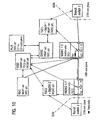
- FIG 10 illustrates call forwarding in the mobile services switching centre MSC to an ISDN subscriber identified by an ISDN no.
- the mobile services switching centre MSC sets up the connection between media gateway MGW1 and media gateway MGW2.
- a subscriber A has set up a call over the ISUP to a user equipment B.
- the TSC1 has set up the context between the terminations Pi1 and Pv11 in media gateway MGW1 and the mobile services switching centre MSC has set up the context including a transcoder between the terminations Po1 and Pv11.
- An assignment request has been sent over the Iu interface, which has set up the user plane between the UE and the media gateway MGW1.
- the mobile services switching centre MSC deducts the transit switching centre TSC2 address and the media gateway MGW2 address out of the forwarded to number. Then the mobile services switching centre MSC forwards the user plane from media gateway MGW1 to media gateway MGW2.
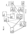
- FIG 11 illustrates an example involving the CW and HOLD functions.
- a subscriber A has set up a call over ISUP to a user equipment B.
- the TSC1 has set up the context between the terminations Pi1 and Pv11 in media gateway MGW1 and the mobile services switching centre MSC has set up the context including a transcoder between the terminations Po1 and Pv11.
- An assignment request has been sent over the Iu interface, which has set up the user plane between the UE and the media gateway MGW1.
- a subscriber C sets up a call over ISUP to user equipment B.
- the transit switching centre TSC2 has set up the context between the terminations Pi2 and Pv21 in media gateway MGW2.
- the mobile services switching centre MSC sets up the context including a transcoder between the terminations Po2 and Pv21 in media gateway MGW2.
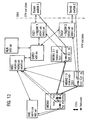
- FIG 12 illustrates MPTY calls, using CCDs only in media gateway MGW3.
- a subscriber A has set up a call over ISUP to a user equipment B.
- a subscriber C has set up a call over ISUP to user equipment B.
- the user equipment B has accepted the waiting call from subscriber C and put the active call on hold.
- the mobile services switching centre MSC selects a media gateway with CCD capabilities. The capabilities are requested by the mobile services switching centre MSC, whenever a new media gateway is introduced to the MSC server or when a previously introduced media gateway comes back into service again.
- the media gateway selection is done according to the following priorities: an media gateway with the active call on (this saves a subsequent set-up from RNC towards the MGW); an media gateway with the call on hold call; or any media gateway with CCD capabilities, chosen depending on the current load situation.
Landscapes
- Engineering & Computer Science (AREA)
- Computer Networks & Wireless Communication (AREA)
- Signal Processing (AREA)
- Business, Economics & Management (AREA)
- General Business, Economics & Management (AREA)
- Multimedia (AREA)
- Mobile Radio Communication Systems (AREA)
- Data Exchanges In Wide-Area Networks (AREA)
- Motorcycle And Bicycle Frame (AREA)
Abstract
Description
- A conventional GSM (Global System for Mobile Communications) or UMTS (Universal Mobile Telecommunications Service) core network uses bearer control and call control. The bearer control is the aspect of signaling related to the control of the selection of a path through the transmission network and utilizing (reserving, releasing and setting up) the required resources. The call control is the aspect of signaling related to the subscriber and service control, taking, e. g., the subscriber state into consideration.
- In the existing implementations of N-ISDN (Integrated Services Digital Network) the call control and the bearer control are integral with one another. A user plane is associated directly with the control servers, such as MSCs( Mobile Services switching Centers) and GMSCs (Gateway MSCs). Thus, the control nodes implement both, application logic for signaling and the user plane.
Knight R. R. and Law B. describe in "The call control protocol in a separated call and bearer environment", published in BT Technical Journal,volume 16Number 2 published April 1998, a system and a protocol with separated call and bearer control. However, the described system does not separate the control nodes from nodes for the transmission of payload. Thus, the control nodes perform both, call control and bearer control, separated only in time. By that, optimised routing of payload is not possible. - The present invention is directed to separation of the call control and the bearer control.
- For implementation of GSM and UMTS core networks there is a new approach to separate call control and bearer control.
- In accordance with the invention, with the implementation of separation between call and bearer control, the following features are described:
- Transfer the media gateway address, a termination and possibly the chosen transcoder in a forward direction. With transferring the transcoder in the forward direction TFO (tandem free operation) or TrFO (transcoder free operation) is possible.
- The application software is independent from the used transmission technology, e. g. STM, ATM, IP.
- Changes to call control and bearer control signaling to achieve the optimized user plane set up.
- Usage of logical points in the media gateway to allow different control servers to control one media gateway.
- Giving a MSC, TSC server the possibility to control several media gateways by allocating one PC per media gateway in the control node.
- The user plane routing for call set-up is optimized significantly.
- The user plane routing for supplementary services CFNREA, CFB, CFNRY, CFU is optimized significantly.
- The user plane routing for supplementary services CW, HOLD is optimized significantly.
- Only one media gateway is used if the call stays inside one network or goes over one network border. If the call goes over two network boarders, then two MGWs are involved, each at the edge to the network.
- The user plane pipe size is optimized by transferring coded (compressed) user plane to the edge of the network or between two MGWs, e. g. for MPTY calls
- Allowing of pooling of conference call devices in MGWs.
- Combining different coded speech streams to one MPTY.
- Further features and advantages of the invention will be readily apparent from the following specification and the drawings.
-
- Figure 1 is a block diagram illustrating basic call set-up for a call from UE to UE, media gateway address being transported in the forward direction;
- Figure 2 is a block diagram illustrating basic call set-up for a call to UE, media gateway address being transported in the forward direction;
- Figure 3 is a block diagram illustrating basic call set-up for call forwarding in GMSC to an ISDN no., media gateway address being transported in the forward direction;
- Figure 4 is a block diagram illustrating basic call set-up for call forwarding in GMSC to UE no., media gateway address being transported in the forward direction;
- Figure 5 is a block diagram illustrating basic call set-up for a call from UE with call forwarding in GMSC to UE, media gateway address being transported in the forward direction;
- Figure 6 is a block diagram illustrating basic call set-up for call forwarding in MSC to an ISDN number, media gateway address being transported in the forward direction;
- Figure 7 is a block diagram illustrating basic call set-up for call waiting and accepting the waiting call in different MGWs, media gateway address being transported in the forward direction;
- Figure 8 is a block diagram illustrating basic call set-up for call waiting and accepting the waiting call in one MGW, media gateway address being transported in the forward direction;
- Figure 9 is a block diagram illustrating basic call set-up for a MPTY call, media gateway address being transported in the forward direction;
- Figure 10 is a block diagram illustrating basic call set-up for call forwarding in MSC to an ISDN number, the MSC setting the connection between MGW1 and media gateway MGW2;
- Figure 11 is a block diagram illustrating basic call set-up for call waiting and hold; and
- Figure 12 is a block diagram illustrating basic call set-up for a MPTY call with CCDs only in MGW3.
-
- The present invention relates to enabling and optimizing call set-up in a telecommunication network with separated call control and bearer control, i.e., set up of a payload connection. The separation of call control and payload transmission means that the signaling between control nodes like MSCs, GMSCs and TSCs takes a different way through the network than the payload. This enables the telecommunication network to perform an optimal routing for the payload, using a minimum of resources. Depending on the call case, originating call, terminating call, internal call or transit call, there are only one or maximally two media gateway necessary.
- The invention particularly relates to a method comprising the transmission of an identification of a selected media gateway in a forward direction. That is, the first control node or the
second control node selects the media gateway depending on: - the call origin;
- the call destination (important for the selection of the terminating control node transit switch or MSC, and for the coding decoding); or
- the required service (voice, fax or else),
- the invoked service, e.g. CFB;
- the coding of the payload (in the case of compressed voice it is sensible to keep the voice data compressed throughout the network to save transmission capacity); or
- the framing of the calls.
- The invention herein relates to implementation of basic call setup, GSM/UMTS supplementary services CFU, CFB, CFNREA, CFNRY, CW, HOLD and MPTY with transporting a media gateway address, a logical point, the chosen coding type and the chosen framing type in a forward direction in networks with separation of call control and bearer control. Call set-up is described in various traffic cases, each illustrated in one of the figures. Each of the figures is a block diagram of a wireless communication system, such as a GSM or UMTS core network, with directional arrows illustrating control signaling between control servers and with MGWs during call set-up for the different traffic cases. The written description herein describes information conveyed in each signal. The particular signal is identified herein and in the drawing with a reference numeral.
- Many of the calls in the traffic cases described herein involve a mobile terminal or a fixed terminal, for example a fax, a PC, or a phone that is located within the network. Such a mobile terminal is referred to herein as User Equipment (UE). The UE communicates with the network via an RNC (Radio Network Controller) using Radio Resource Control (RRC) protocol.
- A logical point is a reference locally generated by a media gateway and only with the media gateway address valid to identify a connection in the control servers e. g. MSC/VLR (MSC/Visitor Location Register), GMSC, TSC and in the RNC. For this purpose a logical point P in a first MGW1 is reserved. This reserved point is sent back in a DCP resource response message to the control server and passed on from this control server to another media gateway MGW2 or RNC, which shall set up an AAL2 connection. In this set up the logical point P is included to identify to which reserved resource in a MGW1 the connection shall be set up. The logical point is equivalent to a termination used in the H.GCP protocol standardized by ITU.
- A control node, such as one of the control servers, discussed above, provides the application logic. The strict separation of the application logic from the user plane handling allows intensive application development and execution. In the described system the control nodes GMSC, MSC, TSC and home location register HLR (only signaling) exist. The interfaces of the control nodes are, e.g., N-ISUP, for call control signaling, DCP signaling for media gateway control and MAP for transferring connectionless signaling between control servers.
- A media gateway (MGW) modifies or switches the user plane. It performs operations such as announcement generation, tone generation, echo cancellation, modem handling for data calls, frame handling and CODEC (transcoder) handling for speech calls.
- A signaling gateway (GW) performs bearer conversion of signaling messages. In UMTS with an ATM core network and ISDN network interworking a conversion from ATM/AAL5 to MTP is done in the signaling gateway. The signaling GW relays the N-ISUP signaling and exchanges the lower transport layer which is carrying the signaling. Therefore the signaling GW is always collocated with e.g. a GMSC or TSC server.
- The backbone network transfers the user plane and the control signaling and can, e.g., be based on STM, ATM or IP. The media gateway is the edge node of the backbone network.
- The following mnemonics, in addition to others which are well known, are used herein:
- AAL2
- ATM
Adaption Layer Type 2 - ATM
- Asynchronous Transfer Mode
- BICC
- Bearer Independent Call Control
- CCD
- Conference Call Device
- CIC
- Circuit Identity Code
- CFB
- Call Forwarding Busy
- CFNREA
- Call Forwarding Not REAchable
- CFNRY
- Call Forwarding No ReplY
- CFU
- Call Forwarding Unconditional
- CM
- Connection Management
- CW
- Call Waiting Supplementary Service
- DCP
- Device Control Protocol, e. g. X-CP
- DPC
- Destination Point Code
- DTAP
- Direct Transfer Application Part
- GMSC
- Gateway MSC
- HLR
- Home Location Register
- HOLD
- Call Hold Supplementary Service
- IP
- Internet Protocol
- ISDN
- Integrated Services Digital Network
- ISUP
- ISDN User Part
- MAP
- Mobile Application Part
- MGW
- Media Gateway
- MSC
- Mobile Services Switching Center
- MPTY
- MultiparTY Supplementary Service
- OPC
- Originating Point Code
- PC
- Point Code
- P
- Logical Point
- RANAP
- Radio Access Network Application Part
- RNC
- Radio Network Controller
- SigGW
- Signaling Gateway
- STM
- Synchronous Transfer Mode
- TSC
- Transit Switching Center
- UE
- User Equipment (mobile)
- In the new network architecture described herein, N-ISDN is used for call control, while STM, AAL2 or IP are used for bearer control and usage of the user plane.
- The generation of control tones are omitted in this description and shall be handled in other known manners.
- The media gateway address can be transported on BICC, ISDN e. g., as a sublayer transport address. To find the TSC and/or the media gateway address, some IN service, the routing analyse or the B-number analyse are used. The TSC is then chosen for an outgoing call to the ISDN. The media gateway is chosen based on capabilities required for handling the call, e. g. which devices such as CODECs, coding, compression, framing scheme, announcement machines, tone senders, or modems are required. In the examples, for simplification, only the B-number analyse is mentioned. The selection depends mainly on the destination. Depending on the destination a group of MGWs with different capabilities can be found. Then a media gateway with the needed capabilities, e.g. CCDs, modem support, Internet connectivity is chosen.
- All resources which have been reserved by a server have to be released by that server. For simplifying the message flows, described below relative to the Figures, the release of media gateway resources is omitted.
- In the examples, a one-to-one relation is assumed between the first control node GMSC/TSC server inside the core network and the first media gateway inside the CN.
- To be able to receive incoming calls over different MGWs, but with the control signaling (IAM) to the same GMSC, the GMSC needs to have one point code per MGW, where the ISDN user plane can terminate. Out of the DPC, to which the IAM was sent, the GMSC can derive the media gateway to which the ISDN user plane was set up.
- To allow that a TSC controls more than one media gateway for outgoing (incoming) traffic the TSC needs one point code per controlled media gateway. For a chosen media gateway the TSC has to use a certain OPC. Depending on the chosen OPC the transit switch can distinguish the ISDN user planes received from different MGWs.
- Another alternative solution to receive or send user plane to different MGWs is that different signaling routes are used between servers, if the user plane is routed via different MGWs.
- A third alternative to receive or send user plane to different MGWs from/to a transit switch and control signaling from/to one server is that different CICs are used for different MGWs, if the user plane is routed via different MGWs.
- The concept of identifying the originating media gateway by OPC used in the IAM message instead of transporting the media gateway address in the IAM message, is also possible through the whole CN, but it requires, for a network of m MGWs, m different point codes in each of the the control servers, which can control the MGWs.
- Another alternative solution to transfer the knowledge of an media gateway from one server to the other is to use different routes for signaling, if the user plane was routed to different MGWs. If a TSC can receive calls from m MGWs, then m different signaling routes towards the RNC are required.
- In the following description of the various drawings, various signal names are used. Some of these signals are conventional in nature. The DTAP messages are defined in GSM 04.08 V8.0.0 and UMTS 24.08 V3.0.0. The RANAP messages are defined in UMTS 25.413 V1.0.2. The MAP messages are defined in GSM 09.02 V 6.3.0 and UMTS 29.002 V 3.3.2. The AAL2 messages are used for bearer control in accordance with the invention. The DCP messages, which are particularly described below, are used for communications between control nodes and the MGWs in connection with resource requests and assignments. The ISDN messages are used for signaling between network control nodes and external ISDN networks. An updated ISDN set of messages is to be used between core network servers. Updated is, for example, the IAM message.
- Figure 1 shows a call from one UE to another UE within the network, with an media gateway address being transported in a forward direction. In this alternative the originating exchange selects the media gateway MGW1, e. g. on traffic and because of location, and transports the media gateway MGW1 address in the forward direction with the ISUP IAM message to the gateway mobile services switching centre GMSC1 and then to the mobile services switching centre MSC2.
- In this case only one media gateway is used, which can be used by all control servers to influence the user plane.
- A transcoder is linked in by the originating MSC as the termination is not known. On the radio network controller RNC1 side, the coding negotiated with the user equipment UE1 is used and on the outgoing side a default coding is used. The terminating mobile services switching centre mobile services switching centre MSC2 chooses the default coding on the one side and the coding, which it negotiated with the user equipment UE2 on the side of the radio network controller RNC2. The following steps in the basic call setup, as with the other examples, below, describe the control signaling in each step and are numbered corresponding to reference numbers in the described figure. The description includes signal protocol, followed by the type of signal.
- 1. DTAP, CM service request
- 2. DTAP, Set-up
- 3. DTAP, Call Proceeding
- 4. DCP, resource request (MGW1)
- 5. DCP, resource response (Pi1, Pv11)
- 6. DCP, Through connect (Pv11, Pi1) The mobile services switching centre MSC1 commands the media gateway MGW1 to backward through connect the incoming point Pi1 and the virtual point Pv11.
- 7. RANAP, Assignment Request
- 8. AAL2, Establish Request
- 9. AAL2, Establish Confirm
- 10. RANAP, Assignment Response
- 11. ISDN, Initial Address Message IAM (MGW1, Pv11, OPC, DPC, CIC) Call set-up is requested from the originating mobile services switching centre MSC1. The media gateway MGW1 address and Pv11 or optional the OPC, DPC, CIC can be used for identifying the incoming connection in the gateway mobile services switching centre GMSC1.
- 12. DCP, resource request (MGW1, Pv11)
- 13. DCP, resource response (Pv12) A virtual point Pv12 is returned from the media gateway MGW1.
- 14. Optional DCP, Through connect (Pv12, Pv11) The gateway mobile services switching centre GMSC1 commands the media gateway MGW1 to through connect the incoming point Pv12 and the virtual point Pv11. Optionally the whole media gateway MGW1 connection can be through connected with one DCP, Through connect (Pi1, Po1) message.
- 15. MAP, SendRouting information request The gateway mobile services switching centre GMSC1 interrogates the home location register HLR for routing information.
- 16. MAP, SendRouting information response The gateway mobile services switching centre GMSC1 receives the forwarding to number and an indication, if a notification shall be given to the calling party.
- 17. Optional ISDN, Address Complete Message ACM The ACM message is sent from the gateway mobile services switching centre GMSC1 to the mobile services switching centre MSC1.
- 18. ISDN, Initial Address Message IAM (MGW1, Pv12, OPC, DPC, CIC) The IAM message is sent from the gateway mobile services switching centre GMSC1 to the mobile services switching centre mobile services switching centre MSC2. The media gateway MGW1 address and Pv12 or optional the OPC, DPC, CIC can be used for identifying the incoming connection in the mobile services switching centre mobile services switching centre MSC2.
- 19. DCP, resource request (MGW1, Pv12) Resources are requested for the call identified by its CIC.
- 20. DCP, resource response (Po1) An outgoing point Po1 is returned from the media gateway MGW1.
- 21. DCP, Through connect (Po1, Pv12) The mobile services switching centre mobile services switching centre MSC2 commands the media gateway MGW1 to through connect the virtual point Pv12 and the outgoing point Po1. Optionally, the media gateway MGW1 connection can be through connected with one DCP, through connect (Pv11, Po1) message.
- 22. RANAP, Paging
- 23. DTAP, Paging Response
- 24. DTAP, Set-up
- 25. DTAP, Call confirmed
- 26. RANAP, Assignment Request
- 27. AAL2, Establish Request
- 28. AAL2, Establish confirm
- 29. RANAP, Assignment Response
- 30. DTAP, Alert
- 31. ISDN, Address Complete Message ACM
- 32. ISDN, Call Proceeding CPG
- 33. DTAP, Connect
- 34. DTAP, Connect ack
- 35. ISUP, Answer Message ANM
- 36. ISUP, Answer Message ANM
- 37. DCP, Through connect (Pv11, Pi1) The mobile services switching centre MSC1 commands the media gateway MGW1 to through connect the incoming point Pi1 and the virtual point Pv11.
- 38. DTAP, Connect
- 39. DTAP, Connect ACK.
-
- Figure 2 illustrates a call to UE originating outside of the network. The media gateway address is again transported in the forward direction. Here a subscriber is calling a served user equipment UE1. In this case only one media gateway is used, which can be used by all control servers to influence the user plane.
- A transcoder is linked in by the terminating mobile services switching centre MSC. On the incoming side, e. g. PCM coding is used and on the outgoing side the coding, negotiated with the user equipment UE1 by the radio network controller RNC, is used.
- 1. ISDN, Initial Address Message IAM (OPC, DPC, CIC)
Call set-up is requested from an external ISDN network for a mobile terminated call
attempt. In this example the gateway mobile services switching centre/transit
switching centre GMSC1/TSC and the
Signaling Gateway 1 are collocated. - 2. DCP, resource request (MGW1, CIC) Resources are requested for the call identified by its CIC, which were chosen by the transit switch of the ISDN network.
- 3. DCP, resource response (Pi1, Pv11) An incoming point Pi1 and a virtual point Pv11 are returned from the media gateway MGW1.
- 4. MAP, SendRouting Information request The gateway mobile services switching centre GMSC1 interrogates the home location register HLR for routing information.
- 5. MAP, SendRouting Information response The gateway mobile services switching centre GMSC1 receives the mobile services switching centre MSC address.
- 6. ISDN, Address Complete Message ACM
The ACM message is sent from the gateway mobile services switching centre/transit
switching centre GMSC1/TSC to the
transit switch 1. - 7. Optional DCP, Through connect (Pi1, Pv11) The gateway mobile services switching centre/transit switching centre GMSC1/TSC commands the media gateway MGW1 to through connect the incoming point Pi1 and the virtual point Pv11. Optionally, the whole media gateway MGW1 connection can be through connected with one DCP, Through connect (Pi1, Po1) message.
- 8. ISDN, Initial Address Message IAM (MGW1, Pv11, OPC, DPC, CIC) The IAM message is sent from the gateway mobile services switching centre/transit switching centre GMSC1/TSC to the mobile services switching centre MSC. The media gateway MGW1 address and Pv11 or optional the OPC, DPC, CIC can be used for identifying the incoming connection in the mobile services switching centre MSC.
- 9. DCP, resource request (MGW1, Pv11) Resources are requested for the call identified by its CIC.
- 10. DCP, resource response (Po1) An outgoing point Po1 is returned from the media gateway MGW1.
- 11. DCP, Through connect (Pv11, Po1) The mobile services switching centre MSC commands the media gateway MGW1 to through connect the virtual point Pv11 and the outgoing point Po1. Optionally, the whole media gateway MGW1 connection can be through connected with one DCP, Through connect (Pi1, Po1) message.
- 12. RANAP, Paging
- 13. DTAP, Paging Response
- 14. DTAP, Set-up
- 15. DTAP, Call confirmed
- 16. RANAP, Assignment Request
- 17. AAL2, Establish Request
- 18. AAL2, Establish confirm
- 19. RANAP, Assignment Response
- 20. DTAP, Alert
- 21. ISDN, Address Complete Message ACM
- 22. ISDN, Call Proceeding CPG
- 23. DTAP, Connect
- 24. DTAP, Connect ack
- 25. ISUP, Answer Message ANM
- 26. ISUP, Answer Message ANM
-
- Figure 3 shows a call forwarding in a GMSC to an ISDN subscriber identified by an ISDN no. outside of the network. The media gateway address is transported in the forward direction.
- For CFNREA in mobile services switching centre MSC the same handling applies as for CFNREA in GMSC. Therefore only the signaling for CFNREA in GMSC are described below.
- Alternatively of transit switching centre TSC2 controlling the set-up from media gateway MGW1 to media gateway MGW2, GMSC can control the set-up as the analyse performed in GMSC optional to transit switching centre TSC2 can also deliver the media gateway MGW2 address as a one-to-one relation exists between both.
- In this case only two MGWs are used, each at the edge of the network.
- A transcoder is optionally linked in by the transit switching centre TSC2 in both media gateways, media gateway MGW1 and media gateway MGW2 to compress the transferred user data. On the STM side, e.g. PCM coding is used and on the other side CN default coding is used.
- 1. ISDN, Initial Address Message IAM (OPC, CPC, CIC)
Call set-up is requested from an external ISDN network for a mobile terminated call
attempt. In this example the GMSC and the
Signaling Gateway 1 are collocated. - 2. DCP, resource request (MGW1, CIC)
Resources are requested for the call identified by its CIC, which were chosen by the
transit switch 1 of the ISDN network. - 3. DCP, resource response (Pi1, Pv11) An incoming point Pi1 and a virtual point Pv11 are returned from the media gateway MGW1.
- 4. MAP, SendRouting Information request The GMSC interrogates the home location register HLR for routing information.
- 5. MAP, SendRouting Information response The GMSC receives the forwarding to number and an indication, if a notification shall be given to the calling party. The forwarded-to number received fromhome location register HLR is analysed and a transit switching centre TSC2 and optional media gateway MGW2 address are received from the B-number analysis.
- 6. ISDN, Address Complete Message ACM
The ACM message is sent from the GMSC to the
transit switch 1. An outband notification can be included in the AM message. This saves signaling, in and out linking of announcement machine and user plane transmission. - 7. Optional DCP, Connect announcement machine (Pi1) Optional the announcement machine is connected, if inband notification is required.
- 8. Optional DCP, Disconnect announcement machine (Pi1) After the announcement the announcement machine is disconnected.
- 9. Optional DCP, Through connect (Pi1, Pv11) The GMSC commands the media gateway MGW1 to through connect the incoming point Pi1 and the virtual point Pv11. Optionally, the whole media gateway MGW1 connection can be through connected with one DCP, Through connect (Pi1, Po1) message. This is in line with ITU N-ISDN specifications.
- 10. ISDN, Initial Address Message IAM (MGW1, PV11, OPC, DPC, CIC) The IAM message is sent from the GMSC to the transit switching centre TSC2, which is controlling the media gateway MGW2. The media gateway MGW1 address and PV11 or optional the OPC, DPC, CIC can be used for identifying the incoming connection in the transit switching centre TSC2.
- 11. DCP, resource request (MGW2) Resources are requested for the call identified by its CIC.
- 12. DCP, resource response (Pi2, Pv21) An incoming point Pi2 and a virtual point Pv21 are returned from the media gateway MGW2.
- 13. DCP, Set-up connection (MGW1, MGW2, Pv11, Pi2) The transit switching centre TSC2 requests resources for an outgoing call identified by its virtual CIC and commands the media gateway MGW1 to set up a connection towards Pi2 in media gateway MGW2.
- 14. AAL2, Establish Request
- 15. AAL2, Establish confirm
- 16. DCP, Set-up connection response (Po1) The media gateway MGW1 signals back that the outgoing connection has been set up successfully and returns an outgoing point Po1.
- 17. DCP, Through connect (Po1, Pv11) The transit switching centre TSC2 commands the media gateway MGW1 to through connect the outgoing point Po1 and the virtual point Pv11. Optionally, the whole media gateway MGW1 connection can be through connected with one DCP, Through connect (Pi1, Po1) message.
- 18. Optional DCP, Through connect (Po1, Pv2) The transit switching centre TSC2 commands the media gateway MGW2 to through connect the incoming point Pi2 and the virtual point Pv21.
- 19. DCP, Set-up connection (MGW2, Pv21)
The transit switching centre TSC2 requests resources for an outgoing call identified
by its virtual CIC and commands the media gateway MGW2 to set up a connection
toward the
transit switch 2. - 20. DCP, Set-up connection response (Po2, CIC) The media gateway MGW2 signals back that the outgoing connection has been set up successfully and returns an outgoing point Po2.
- 21. DCP, Through connect (Po2, Pv21) The transit switching centre TSC2 commands the media gateway MGW2 to through connect the outgoing point Po2 and the virtual point Pv21.
- 22. ISDN, Initial Address Message IAM (OPC, DPC, CIC)
The IAM message is sent from the transit switching centre TSC2 to the
transit switch 2. - 23. ISDN, Address Complete Message ACM
- 24. ISDN, Call Proceeding CPG
- 25. ISDN, Call Proceeding CPG
- 26. ISDN, Answer Message ANM
- 27. ISDN, Answer Message ANM The ANM message is passed on by the transit switching centre TSC2.
- 28. ISDN, Answer ANM The ANM message is passed on by the GMSC.
-
- Figure 4 illustrates call forwarding in GMSC to a UE subscriber identified by a UE no. in the network. The media gateway address is transported in the forward direction.
- For subsequent forwarding to UE in GMSC instead of gateway mobile services switching centre GMSC2 several GMSCs have to be included. In this case only one media gateway is used, which can be used by all control servers to influence the user plane. A transcoder is linked in by the terminating mobile services switching centre MSC. On the incoming side, e. g. PCM coding is used and on the outgoing side the coding, negotiated with the user equipment UE1, is used.
- 1. ISDN, Initial Address Message IAM (OPC, DPC, CIC)
Call set-up is requested from an external ISDN network for a mobile terminated call
attempt. In this example the gateway mobile services switching centre/transit
switching centre GMSC1/TSC1 and the
Signaling Gateway 1 are collocated. - 2. DCP, resource request (MGW1, CIC) Resources are requested for the call identified by its CIC, which were chosen by the transit switch of the ISDN network.
- 3. DCP, resource response (Pi1, Pv11) An incoming point Pi1 and a virtual point Pv11 are returned from the media gateway MGW1.
- 4. MAP, SendRouting Information request The GSMC interrogates the home location register HLR for routing information.
- 5. MAP, SendRouting Information response The gateway mobile services switching centre GMSC1 receives the forwarding to number and an indication, if a notification shall be given to the calling party.
- 6. ISDN, Address Complete Message ACM
The ACM message is sent from the gateway mobile services switching centre/transit
switching centre GMSC1/TSC1 to the
transit switch 1. An outband notification can be included in the ACM message. This saves signaling, in and out linking of announcement machine and user plane transmission. - 7. Optional DCP, Connect announcement machine (Pi2) Optionally the announcement machine is connected, if inband notification is required.
- 8. Optional DCP, Disconnect announcement machine (Pi1) After the announcement the announcement machine is disconnected.
- 9. Optional DCP, Through connect (Pi1, Pv11) The gateway mobile services switching centre/transit switching centre GMSC1/TSC1 commands the media gateway MGW1 to through connect the incoming point Pi1 and the virtual point Pv11. Optionally, the whole media gateway MGW1 connection can be through connected with one DCP, Through connect (Pi1, Po1) message.
- 10. ISDN, Initial Address Message IAM (MGW1, PV11, OPC, DPC, CIC) The IAM message is sent from the gateway mobile services switching centre/transit switching centre GMSC1/TSC1 to the gateway mobile services switching centre GMSC2. The media gateway MGW1 address and Pv11 or optional the OPC, DPC, CIC can be used for identifying the incoming connection in the gateway mobile services switching centre GMSC2.
- 11. DCP, resource request (MGW1, Pv11) Resources are requested for the call identified by its CIC.
- 12. DCP, resource response (Pv12) A virtual point Pv12 is returned from the media gateway MGW1.
- 13. Optional DCP, Through connect (Pv11, Pv12) The gateway mobile services switching centre GMSC2 commands the media gateway MGW1 to through connect the virtual point Pv11 and the virtual point Pv12. Optionally, the whole media gateway MGW1 connection can be through connected with one DCP, Through connect (Pi1, Po1) message.
- 14. MAP, SendRouting Information request The gateway mobile services switching centre GMSC2 receives the mobile services switching centre MSC address from HLR.
- 15. MAP, SendRouting Information request The gateway mobile services switching centre GMSC2 receives the mobile services switching centre MSC address from HLR.
- 16. ISDN, Initial Address Message IAM (MGW1, PV12, OPC, DPC, CIC) The IAM message is sent from the gateway mobile services switching centre GMSC2 to the mobile services switching centre MSC.
- 17. DCP, resource request (MGW1, Pv12) Resources are requested for the call identified by its CIC.
- 18. DCP, resource response (Po1) An outgoing point Po1 is returned from the media gateway MGW1.
- 19. DCP, Through connect (Po1, Pv12) The mobile services switching centre MSC commands the media gateway MGW1 to through connect the virtual point Pv12 and the outgoing point Po1. Optionally, the whole media gateway MGW1 connection can be through connected with one DCP, Through connect (Pi1, Po1) message.
- 20. RANAP, Paging
- 21. DTAP, Paging Response
- 22. DTAP, Set-up
- 23. DTAP, Call confirmed
- 24. RANAP, Assignment Request
- 25. AAL2, Establish Request
- 26. AAL2, Establish confirm
- 27. RANAP, Assignment Response
- 28. DTAP, Alert
- 29. ISDN, Address Complete Message ACM
- 30. ISDN, Call Proceeding CPG
- 31. ISDN, Call Proceeding CPG
- 32. DTAP, Connect
- 33. DTAP, Connect ack
- 34. ISUP, Answer Message ANM
- 35. ISUP, Answer Message ANM
- 36. ISUP, Answer Message ANM
-
- Figure 5 illustrates a call from UE with Call forwarding in GMSC to a UE subscriber identified by a UE no. in the network. The media gateway address is transported in the forward direction.
- There are three alternatives for assuring user plane optimised routing. In the first alternative the media gateway MGW1 is chosen in the mobile services switching centre mobile services switching centre MSC2. Then the media gateway MGW1 address is transferred in the backward direction with ISUP ACM/CPG or some new message to the originating mobile services switching centre MSC1. The mobile services switching centre MSC1 then commands radio network controller RNC1 to set-up the user plane connection towards media gateway MGW1 and commands media gateway MGW1 to through connect. Then mobile services switching centre mobile services switching centre MSC2 commands radio network controller RNC2 to set up the user plane connection towards media gateway MGW1.
- The second alternative commands the radio network controllers to connect without in linking of an media gateway and only possible for the mobile to mobile case.
- The third alternative is that the originating exchange selects the media gateway MGW1 and transports the media gateway MGW1 address in the forward direction with the ISUP IAM message to the mobile services switching centre mobile services switching centre MSC2. This alternative can be optimised by combining it with the first alternative. So if a media gateway address is received in the backward direction, then the mobile services switching centre MSC1 can perform a subsequent assignment towards radio network controller RNC1. Below the third alternative without optimisation is described.
- For subsequent forwarding to UE in GMSC instead of gateway mobile services switching centre GMSC2 several GMSCs have to be included. In this case only one media gateway is used, which can be used only by all control servers to influence the user plane. A transcoder is linked in by the originating MSC as the termination is not known. On the radio network controller RNC1 side, the coding is negotiated with the user equipment UE1 is used and on the outgoing side a default coding is used. The terminating mobile services switching centre mobile services switching centre MSC2 chooses the default coding on the one side and the coding, which it negotiated with the user equipment UE2 on the side of radio network controller RNC2. If only media gateway is used that comprises both linked in CODECs, the media gateway can decide to link out both CODECs if the coding towards user equipment UE1 and user equipment UE2 is of the same type.
- 1. DTAP, CM service request
- 2. DTAP, Set-up
- 3. DTAP, Call Proceeding
- 4. DCP, resource request (MGW1)
- 5. DCP, resource response (Pi1, Pv11) An incoming point Pi1 and a virtual point Pv11 are returned from the media gateway MGW1.
- 6. DCP, Through connect (Pv11, Pi1) The mobile services switching centre MSC1 commands the media gateway MGW1 to backward through connect the incoming point Pi1 and the virtual point Pv11.
- 7. RANAP, Assignment Request
- 8. AAL2, Establish Request
- 9. AAL2, Establish Confirm
- 10. RANAP, Assignment Response
- 11. ISDN, Initial Address Message IAM (MGW1, Pv11, OPC, DPC, CIC) Call set-up is requested from the originating mobile services switching centre MSC1. The media gateway MGW1 address and Pv11 or optionally the OPC, DPC, CIC can be used for identifying the incoming connection in the gateway mobile services switching centre/transit switching centre GMSC1/TSC.
- 12. DCP, resource request (MGW1, Pv11)
- 13. DCP, resource response (Pv12) A virtual point Pv12 is returned from the media gateway MGW1.
- 14. Optional DCP, Through connect (Pv12, Pv11) The gateway mobile services switching centre GMSC1 commands the media gateway MGW1 to through connect the incoming point Pv12 and the virtual point Pv11. Optionally, the whole media gateway MGW1 connection can be through connected with one DCP, Through connect (Pi1, Po1) message.
- 15. MAP, SendRouting Information request The gateway mobile services switching centre GMSC1 interrogates the home location register HLR for routing information.
- 16. MAP, SendRouting Information response The gateway mobile services switching centre GMSC1 receives the forwarding to number and an indication, if a notification shall be given to the calling party.
- 17, Optional ISDN, Address Complete Message ACM The ACM message is send from the gateway mobile services switching centre GMSC1 to the MSC.
- 18. ISDN, Initial Address Message IAM (MGW1, Pv12, OPC, DPC, CIC) The IAM message is send from the gateway mobile services switching centre GMSC1 to the gateway mobile services switching centre GMSC2. The media gateway MGW1 address and Pv12 or optionally the OPC, DPC, CIC can be used for identifying the incoming connection in the gateway mobile services switching centre GMSC2.
- 19. DCP, resource request (MGW1, Pv12) Resources are requested for the call identified by its CIC.
- 20. DCP, resource response (Pv13) A virtual point Pv13 is returned from the media gateway MGW1.
- 21. Optional DCP, Through connect (Pv13, Pv12) The gateway mobile services switching centre GMSC2 commands the media gateway MGW1 to through connect the virtual point Pv13 and the virtual point Pv12. Optionally, the media gateway MGW1 connection can be through connected with one DCP, Through connect (Pv11, Po1) message.
- 22. MAP, SendRouting Information request The gateway mobile services switching centre GMSC2 interrogates the home location register HLR for routing information.
- 23. MAP, SendRouting Information response The gateway mobile services switching centre GMSC2 receives the MSC address from HLR.
- 24. ISDN, Initial Address Message IAM (MGW1, Pv13, OPC, DPC, CIC) The IAM message is sent from the gateway mobile services switching centre GMSC2 to the MSC.
- 25. DCP, resource request (MGW1, Pv13) Resources are requested for the call identified by its CIC.
- 26. DCP, resource response (Po1) An outgoing point Po1 is returned from the media gateway MGW1.
- 27. DCP, Through connect (Po1, Pv13) The mobile services switching centre mobile services switching centre MSC2 commands the media gateway MGW1 to through connect the virtual point Pv13 and the outgoing point Po1. Optionally, the media gateway MGW1 connection can be through connected with one DCP, Through connect (Pv11, Po1) message.
- 28. RANAP, Paging
- 29. DTAP, Paging Response
- 30. DTAP, Set-up
- 31. DTAP, Call confirmed
- 32. RANAP, Assignment Request
- 33. AAL2, Establish Request
- 34. AAL2, Establish confirm
- 35. RANAP, Assignment Response
- 36. DTAP, Alert
- 37. ISDN, Address Complete Message ACM
- 38. ISDN, Call Proceeding CPG
- 39. ISDN, Call Proceeding CPG
- 40. ISDN, Call Proceeding CPG
- 41. DTAP, Connect
- 42. DTAP, Connect ack
- 43. ISUP, Address Complete Message ANM
- 44. ISUP, Address Complete Message ANM
- 45. ISUP, Address Complete Message ANM
- 46. DCP, Through connect (Pv11, Pi1) The mobile services switching centre MSC1 commands the media gateway MGW1 to through connect the incoming point Pi1 and the virtual point Pv11.
- 47. DTAP, Connect
- 48. DTAP, Connect ACK
-
- Figure 6 illustrates call forwarding in mobile services switching centre MSC to an ISDN subscriber identified by an ISDN no. The media gateway address is transported in the forward direction.
- In this example the conditional call forwarding in mobile services switching centre MSC is described. The case describes CFNRY, if the UE user does not answer the call, and the call has to be forwarded to an ISDN no. In case of CFNREA, if the UE does not answer the paging, steps 12 to 22 are to be omitted. In the current example only two MGWs are used, each at the edge of the network. A transcoder is optionally linked in by the TSC in both media gateways to compress the transferred user data. On the STM side, e. g., PCM coding is used and on the other side CN default coding is used.
- 1. ISDN, Initial Address Message IAM (OPC, DPC, CIC)
Call set-up is requested from an external ISDN network for a mobile terminated call
attempt. In this example the gateway mobile services switching centre/transit
switching centre GMSC1/TSC1 and the
Signaling Gateway 1 are collocated. - 2. DCP, resource request (MGW1, CIC) Resources are requested for the call identified by its CIC, which were chosen by the transit switch of the ISDN network.
- 3. DCP, resource response (Pi1, Pv11) An incoming point Pi1 and a virtual point Pv11 are returned from the media gateway MGW1.
- 4. MAP, SendRouting Information request The gateway mobile services switching centre GMSC1 interrogates the home location register HLR for routing information.
- 5. MAP, SendRouting Information response The gateway mobile services switching centre GMSC1 receives the mobile services switching centre MSC address.
- 6. ISDN, Address Complete Message ACM
The ACM message is sent from the GMSC to the
transit switch 1. - 7. Optional DCP, Through connect (Pi1, Pv11) The GMSC commands the media gateway MGW1 to through connect the incoming point Pi1 and the virtual point Pv11. Optionally, the whole media gateway MGW1 connection can be through connected with one DCP, Through connect (Pi1, Po1) message.
- 8. ISDN, Initial Address Message IAM (MGW1, Pv11, OPC, DPC, CIC) The IAM message is sent from the GMSC to the mobile services switching centre MSC. The media gateway MGW1 address and Pv11 or optional the OPC, DPC, CIC can be used for identifying the incoming connection in the mobile services switching centre MSC.
- 9. DCP, resource request (MGW1, Pv11) Resources are requested for the call identified by its CIC.
- 10. DCP, resource response (Po1) An outgoing point Po1 is returned from the media gateway MGW1.
- 11. DCP, Through connect (Pv11, Po1) The mobile services switching centre MSC commands the media gateway MGW1 to through connect the virtual point Pv11 and the outgoing point Po1. Optionally the whole media gateway MGW1 connection can be through connected with one DCP, Through connect (Pi1, Po1) message.
- 12. RANAP, Paging
- 13. DTAP, Paging Response
- 14. DTAP, Set-up
- 15. DTAP, Call confirmed
- 16. RANAP, Assignment Request
- 17. AAL2, Establish Request
- 18. AAL2, Establish confirm
- 19. RANAP, Assignment Response
- 20. DTAP, Alert
- 21. ISDN, Address Complete Message ACM
- 22. ISDN, Call Proceeding CPG
- 23. RANAP, Iu release command
- 24. AAL2, Release request
- 25. AAL2, Release confirm
- 26. RANAP, Iu release complete
- 27. Optional DCP, Connect announcement machine (Pv11) Optionally, the announcement machine is connected, if inband notification is required.
- 28. Optional DCP, Disconnect announcement machine (Pv11) After the announcement the announcement machine is disconnected.
- 29. ISDN, Initial Address Message IAM (MGW1, Po1, OPC, DPC, CIC) The IAM message is send from the mobile services switching centre MSC to the transit switching centre TSC2. The media gateway MGW1 address and Pv11 or optionally the OPC, DPC, CIC can be used for identifying the incoming connection in the mobile services switching centre MSC.
- 30. DCP, resource request (MGW2) Resources are requested for the call identified by its CIC.
- 31. DCP, resource response (Pi2, Pv21) An incoming point Pi2 and a virtual point Pv21 are returned from the media gateway MGW2.
- 32. DCP, Set-up connection (MGW1, media gateway MGW2, Po1, Pi2) The transit switching centre TSC2 requests the already reserved resources for an outgoing call identified by its virtual CIC and commands the media gateway MGW1 to set up a connection towards Pi2 in media gateway MGW2.
- 33. AAL2, Establish Request
- 34. AAL2, Establish confirm
- 35. DCP, Set-up connection response (Po1) The media gateway MGW1 signals back that the outgoing connection has been set up successful and returns an outgoing point Po1.
- 36. DCP, Through connect (Po1, Pv11) The transit switching centre TSC2 commands the media gateway MGW1 to through connect the outgoing point Po1 and the virtual point Pv11. If optional DCP, Through connect (Pi2, Pv11) is omitted, instead of Pv11 Pi1 must be used.
- 37. Optional DCP, Through connect (Pi2, Pv21) The transit switching centre TSC2 commands the media gateway MGW2 to through connect the incoming point Pi2 and the virtual point Pv21.
- 38. DCP, Set-up connection (MGW2, Pv21)
The transit switching centre TSC2 requests resources for an outgoing call identified
by its virtual CIC and commands the media gateway MGW2 to set up a connection
towards the
transit switch 2. - 39. DCP, Set-up connection response (Po2, CIC) The media gateway MGW2 signals back that the outgoing connection has been set up successfully and returns an outgoing point Po2.
- 40. DCP, Through connection (Po2, Pv21) The transit switching centre TSC2 commands the media gateway MGW2 to through connect the outgoing point Po2 and the virtual point Pv21.
- 41. ISDN, Initial Address Message IAM (OPC, DPC, CIC)
The IAM message is send from the transit switching centre TSC2 to the
transit switch 2. - 42. ISDN, Address Complete Message ACM
- 43. ISDN, Call Proceeding CPG
- 44. ISDN, Call Proceeding CPG
- 45. ISDN, Call Proceeding CPG
- 46. ISDN, Answer Message ANM
- 47. ISDN, Answer Message ANM
- 48. ISDN, Answer Message ANM
- 49. ISDN, Answer Message ANM
-
- Figure 7 illustrates call waiting and accepting the waiting call in different MGWs. The media gateway address is transported in the forward direction.
- Here a subscriber B is calling a served user equipment A, who has the supplementary services CW and HOLD. After the call from B to A is active another terminating call from a subscriber C to A is received. Subscriber A accepts the waiting call from C and therefore has to put the call to B on hold. The user plane is routed directly to the media gateway of the active call. This is the optimal way for the transmission, but it requires subsequent assignment over the Iu interface.
- In this case only one media gateway is used for each call, which can be used by all control servers to influence the user plane. No user plane connection is needed between the MGWs.
- 1. ISDN, Initial Address Message IAM (OPC, DPC, CIC)
Call set-up is requested from an external ISDN network for a mobile terminated call
attempt. In this example the gateway mobile services switching centre/transit
switching centre GMSC1/TSC and the
Signaling Gateway 1 are collocated. - 2. DCP, resource request (MGW1, CIC) Resources are requested for the call identified by its CIC, which were chosen by the transit switch of the ISDN network.
- 3. DCP, resource response (Pi1, Pv11) An incoming point Pi1 and a virtual point Pv11 are returned from the media gateway MGW1.
- 4. MAP, SendRouting Information request The gateway mobile services switching centre GMSC1 interrogates the home location register HLR for routing information.
- 5. MAP, SendRouting Information response The gateway mobile services switching centre GMSC1 receives the mobile services switching centre MSC address.
- 6. ISDN, Address Complete Message ACM
The ACM message is sent from the gateway mobile services switching centre/transit
switching centre GMSC1/TSC to the
transit switch 1. - 7. Optional DCP, Through connect (Pi1, Pv11) The gateway mobile services switching centre/transit switching centre GMSC1/TSC commands the media gateway MGW1 to through connect the incoming point Pi1 and the virtual point Pv11. Optionally, the whole media gateway MGW1 connection can be through connected with one DCP, Through connect (Pi1, Po1) message.
- 8. ISDN, Initial Address Message IAM (MGW1, Pv11, OPC, DPC, CIC) The IAM message is sent from the gateway mobile services switching centre/transit switching centre GMSC1/TSC to the mobile services switching centre MSC. The media gateway MGW1 address and Pv11 or optionally the OPC, DPC, CIC can be used for identifying the incoming connection in the mobile services switching centre MSC.
- 9. DCP, resource request (MGW1, Pv11) Resources are requested for the call identified by its CIC.
- 10. DCP, resource response (Po1) An outgoing point Po1 is returned from the media gateway MGW1.
- 11. DCP, Through connect (Pv11, Po1) The mobile services switching centre MSC commands the media gateway MGW1 to through connect the virtual point Pv11 and the outgoing point Po1. Optionally the whole media gateway MGW1 connection can be through connected with one DCP, Through connect (Pi1, Po1) message.
- 12. RANAP, Paging
- 13. DTAP, Paging Response
- 14. DTAP, Set-up
- 15. DTAP, Call confirmed
- 16. RANAP, Assignment Request
- 17. AAL2, Establish Request
- 18. AAL2, Establish confirm
- 19. RANAP, Assignment Response
- 20. DTAP, Alert
- 21. ISDN, Address Complete Message ACM
- 22. ISDN, Call Proceeding CPG
- 23. DTAP, Connect
- 24. DTAP, Connect ack
- 25. ISUP, Answer Message ANM
- 26. ISUP, Answer Message ANM
- 27. ISDN, Initial Address Message IAM (OPC, DPC, CIC)
Call set-up is requested from an external ISDN network for a mobile terminated call
attempt. In this example the gateway mobile services switching centre GMSC2 and
the
Signaling Gateway 2 are collocated. - 28. DCP, resource request (MGW2, CIC)
Resources are requested for the call identified by its CIC, which were chosen by the
transit switch 2 of the ISDN network. - 29. DCP, resource response (Pi2, Pv11) An incoming point Pi2 and a virtual point Pv21 are returned from the media gateway MGW2.
- 30. MAP, SendRouting Information request The gateway mobile services switching centre GMSC2 interrogates the home location register HLR for routing information.
- 31. MAP, SendRouting Information response The gateway mobile services switching centre GMSC2 receives the mobile services switching centre MSC address.
- 32. ISDN, Address Complete Message ACM
The ACM message is send from the gateway mobile services switching centre
GMSC2 to the
transit switch 2. - 33. Optional DCP, Through connect (Pi2, Pv21) The gateway mobile services switching centre GMSC2 commands the media gateway MGW2 to through connect the incoming point Pi2 and the virtual point Pv21. Optionally, the whole media gateway MGW2 connection can be through connected with one DCP, Through connect (Pi2, Po2) message.
- 34. ISDN, Initial Address Message IAM (MGW2, Pv21, OPC, DPC, CIC) The IAM message is sent from the gateway mobile services switching centre GMSC2 to the mobile services switching centre MSC. The media gateway MGW2 address and Pv21 or optionally the OPC, DPC, CIC can be used for identifying the incoming connection in the mobile services switching centre MSC.
- 35. DCP, resource request (MGW2, Pv21) Resources are requested for the call identified by its CIC.
- 36. DCP, resource response (Po2) An outgoing point Po2 is returned from the media gateway MGW2.
- 37. DCP, Through connect (Pv21, Po1) The mobile services switching centre MSC commands the media gateway MGW2 to through connect the virtual point Pv21 and the outgoing point Po2. Optionally, the whole media gateway MGW2 connection can be through connected with one DCP, Through connect (Pi2, Po2) message.
- 38. RANAP, Paging
- 39. DTAP, Paging Response
- 40. DTAP, Set-up
- 41. DTAP, Call confirmed
- 42. DTAP, Alert
- 43. ISDN, Address Complete Message ACM
- 44. ISDN, Call Proceeding CPG
- 45. DTAP, HOLD (B)
- 46. DTAP, HOLD ACK
- 47. ISUP, Call Proceeding Message CPG (B held)
- 48. ISUP, Call Proceeding Message CPG (B held)
- 49. RANAP, Assignment Request
- 50. AAL2, Release Request
- 51. AAL2, Release Confirm
- 52. AAL2, Establish Request
- 53. AAL2, Establish confirm
- 54. RANAP, Assignment Response
- 55. DTAP, Connect
- 56. DTAP, Connect ack
- 57. ISUP, Answer Message ANM
- 58. ISUP, Answer Message ANM
-
- Figure 8 illustrates call waiting and accepting the waiting call in one media gateway. The media gateway address is transported in the forward direction.
- Here a subscriber B is calling a served mobile subscriber A, who has the supplementary services CW and HOLD. After the call from B to A is active another terminating call from a subscriber C over media gateway MGW2 to A is received. Subscriber A accepts the waiting call from C and therefore has to put the call to B on hold. The user plane is routed from media gateway MGW2 to the media gateway MGW1 of the first active call. The active call becomes then the held call. It is assumed that both the active and the waiting call use the same service, e. g., speech, so that the AAL2 connection between radio network controller RNC and media gateway MGW1 can be reused. This allows fast switches between the active and the held call and if a multiparty is required later on, only a conference call device has to be linked in the media gateway MGW1.
- In this case only one media gateway is used for each call, which can be used by all control servers to influence the user plane. The user plane connections are gathered at one media gateway. This allows faster switches between the calls from B and C. A transcoder is linked in by the terminating mobile services switching centre MSC for each call. On the incoming side, e. g., PCM coding is used and on the outgoing side the coding, negotiated with the UEs, is used.
- 1. ISDN, Initial Address Message IAM (OPC, DPC, CIC)
Call set-up is requested from an external ISDN network for a mobile terminal call
attempt. In this example the gateway mobile services switching centre/transit
switching centre GMSC1/TSC and the
Signaling Gateway 1 are collocated. - 2. DCP, resource request (MGW1, CIC) Resources are requested for the call identified by its CIC, which were chosen by the transit switch of the ISDN network.
- 3. DCP, resource response (Pi2, Pv11) An incoming point Pi1 and a virtual point Pv11 are returned from the media gateway MGW1.
- 4. MAP, SendRouting Information request The gateway mobile services switching centre GMSC1 interrogates the home location register HLR for routing information.
- 5. MAP, SendRouting Information response The gateway mobile services switching centre GMSC1 receives the mobile services switching centre MSC address.
- 6. ISDN, Address Complete Message ACM
The ACM message is send from the gateway mobile services switching centre/transit
switching centre GMSC1/TSC to the
transit switch 1. - 7. Optional DCP, Through connect (Pi1, Pv11) The gateway mobile services switching centre/transit switching centre GMSC1/TSC commands the media gateway MGW1 to through connect the incoming point Pi1 and the virtual point Pv11. Optionally, the whole media gateway MGW1 connection can be through connected with one DCP, Through connect (Pi2, Po2) message.
- 8. ISDN, Initial Address Message IAM (MGW1, Pv11, OPC, DPC, CIC) The IAM message is sent from the gateway mobile services switching centre/transit switching centre GMSC1/TSC to the mobile services switching centre MSC. The media gateway MGW1 address and Pv11 or optional the OPC, DPC, CIC can be used for identifying the incoming connection in the mobile services switching centre MSC.
- 9. DCP, resource request (MGW1, Pv11) Resources are requested for the call identified by its CIC.
- 10. DCP, resource response (Po1) An outgoing point Po1 is returned from the media gateway MGW1.
- 11. DCP, Through connect (Pv11, Po1) The mobile services switching centre MSC commands the media gateway MGW1 to through connect the virtual point Pv11 and the outgoing point Po1. Optionally, the whole media gateway MGW1 connection can be through connected with one DCP, Through connect (Pi1, Po1) message.
- 12. RANAP, Paging
- 13. DTAP, Paging Response
- 14. DTAP, Set-up
- 15. DTAP, Call confirmed
- 16. RANAP, Assignment Request
- 17. AAL2, Establish Request
- 18. AAL2, Establish confirm
- 19. RANAP, Assignment Response
- 20. DTAP, Alert
- 21. ISDN, Address Complete Message ACM
- 22. ISDN, Call Proceeding CPG
- 23. DTAP, Connect
- 24. DTAP, Connect ack
- 25. ISUP, Answer Message ANM
- 26. ISUP, Answer Message ANM
- 27. ISDN, Initial Address Message IAM (OPC, DPC, CIC)
Call set-up is requested from an external ISDN network for a mobile terminated call
attempt. In this example the gateway mobile services switching centre GMSC2 and
the
Signaling Gateway 2 are collocated. - 28. DCP, resource request (MGW2, CIC)
Resources are requested for the call identified by its CIC, which were chosen by the
transit switch 2 of the ISDN network. - 29. DCP, resource response (Pi2, Pv11) An incoming point Pi2 and a virtual point Pv21 are returned from the media gateway MGW2.
- 30. MAP, SendRouting Information request The gateway mobile services switching centre GMSC2 interrogates the home location register HLR for routing information.
- 31. MAP, SendRouting Information response The gateway mobile services switching centre GMSC2 receives the mobile services switching centre MSC address.
- 32. ISDN, Address complete Message ACM
The ACM message is send from the gateway mobile services switching centre
GMSC2 to the
transit switch 2. - 33. Optional DCP, Through connect (Pi2, Pv21) The gateway mobile services switching centre GMSC2 commands the media gateway MGW2 to through connect the incoming point Pi2 and the virtual point Pv21. Optionally, the whole media gateway MGW2 connection can be through connected with one DCP, Through connect (Pi2, Po2) message.
- 34. ISDN, Initial Address Message IAM (MGW2, Pv21, OPC, DPC, CIC) The IAM message is sent from the gateway mobile services switching centre GMSC2 to the mobile services switching centre MSC. The media gateway MGW2 address and Pv21 or optionally the OPC, DPC, CIC can be used for identifying the incoming connection in the mobile services switching centre MSC.
- 35. DCP, resource request (MGW1) Resources are requested for incoming AAL2 connection.
- 36. DCP, resource response (Pv12, Pi11) An incoming point Pi11 is returned from the media gateway MGW1.
- 37. Optional DCP, Through connect (Pv12, Pi11) The mobile services switching centre MSC commands the media gateway MGW1 to through connect the virtual point Pv12 and the incoming point Pi11. Optionally, the whole media gateway MGW1 connection can be through connected with one DCP, Through connect (Pi11, Po2) message.
- 38. RANAP, Paging
- 39. DTAP, Paging Response
- 40. DTAP, Set-up
- 41. DTAP, Call confirmed
- 42. DTAP, Alert
- 43. ISDN, Address Complete Message ACM
- 44. ISDN, Call Proceeding CPG
- 45. DTAP, HOLD (B)
- 46. DTAP, HOLD ACK
- 47. ISUP, Call Proceeding Message CPG (B held)
- 48. ISUP, Call Proceeding Message CPG (B held)
- 49. DCP, Set-up connection (MGW1, media gateway MGW2, Pv21, Pi11) MSC requests resources for an outgoing AAL2 connection and commands the media gateway MGW1 to set up a connection towards Pi11 in media gateway MGW1.
- 50. AAL2, Establish Request
- 51. AAL2, Establish confirm
- 52. DCP, Set-up connection response (Po2) The media gateway MGW2 signals back that the outgoing connection has been set up and returns an outgoing point Po2.
- 53. DCP, Through connect (Pv21, Po2) The mobile services switching centre MSC commands the media gateway MGW2 to through connect the virtual point Pv21 and the outgoing point Po2. Optionally, the whole media gateway MGW2 connection can be through connected with one DCP, Through connect (Pi2, Po2) message.
- 54. DCP, Disconnect (Po1, Pv11)
- 55. DCP, Through connect (Pv12, Po2) The mobile services switching centre MSC commands the media gateway MGW1 to through connect the virtual point Pv12 and the outgoing point Po2. Optionally, the whole media gateway MGW2 connection can be through connected with one DCP, Through connect (Pi2, Po2) message. This connects the existing user plane between radio network controller RNC and media gateway MGW1 with the user plane of subscriber C.
- 56. DTAP, Connect
- 57. DTAP, Connect ack
- 58. ISUP, Answer Message ANM
- 59. ISUP, Answer Message ANM
-
- Figure 9 illustrates a MPTY call. The media gateway address is transported in the forward direction.
- Here a subscriber B is calling a served user equipment A, who has the supplementary services CW, HOLD and MPTY. After the call from B to A is active another terminating call from a subscriber C over media gateway MGW2 to A is received. Subscriber A accepts the waiting call from C and therefore has to put the call to B on hold. The user plane of the second call is routed from media gateway MGW2 to the media gateway MGW1 of the first active call. Then mobile services switching centre MSC commands media gateway MGW1 to switch from the former active call to the waiting call. The active call becomes then the held call. It is assumed that both the active and the waiting call use the same service, e. g., speech, so that the AAL2 connection between radio network controller RNC and media gateway MGW1 can be reused. Now a multiparty is invoked by subscriber A. Therefore the mobile services switching centre MSC links in a conference call device (CCD). Before the user planes can be connected, the user planes all must be in the same format, e. g., PCM 64 kbit/s.
- In this case only one media gateway is used for each call, which can be used by all control servers to influence the user plane. The user plane connections are gathered at one media gateway. This allows faster switches between the calls from B and C.
- A transcoder is linked in by the terminating mobile services switching centre MSC for each call. On the incoming side, e. g., PCM coding is used and on the outgoing side the coding, negotiated with the UEs, is used. The linked in conference bridge is assumed to be a PCM conference bridge, therefore at each leg coding from the received coding to PCM coding applies. This allows gathering of different coded data streams.
- 1. ISDN, Initial Address Message IAM (OPC, DPC, CIC)
Call set-up is requested from an external ISDN network for a mobile terminated call
attempt. In this example the gateway mobile services switching centre/transit
switching centre GMSC1/TSC and the
Signaling Gateway 1 are collocated. - 2. DCP, resource request (MGW1, CIC) Resources are requested for the call identified by its CIC, which were chosen by the transit switch of the ISDN network.
- 3. DCP, resource response (Pi1, Pv11) An incoming point Pi1 and a virtual point Pv11 are returned from the media gateway MGW1.
- 4. MAP, SendRouting Information request The gateway mobile services switching centre GMSC1 interrogates the home location register HLR for routing information.
- 5. MAP, SendRouting Information response The gateway mobile services switching centre GMSC1 receives the mobile services switching centre MSC address.
- 6. ISDN, Address Complete Message ACM
The ACM message is send from the gateway mobile services switching centre/transit
switching centre GMSC1/TSC to the
transit switch 1. - 7. Optional DCP, Through connect (Pi1, Pv11) The gateway mobile services switching centre/transit switching centre GMSC1/TSC commands the media gateway MGW1 to through connect the incoming point Pi1 and the virtual point Pv11. Optionally, the whole media gateway MGW1 connection can be through connected with one DCP, Through connect (Pi1, Po1) message.
- 8. ISDN, Initial Address Message IAM (MGW1, Pv11, OPC, DPC, CIC) The IAM message is sent from the gateway mobile services switching centre/transit switching centre GMSC1/TSC to the mobile services switching centre MSC. The media gateway MGW1 address and Pv11 or optionally the OPC, DPC, CIC can be used for identifying the incoming connection in the mobile services switching centre MSC.
- 9. DCP, resource request (MGW1, Pv11) Resources are requested for the call identified by its CIC.
- 10. DCP, resource response (Po1) An outgoing point Po1 is returned from the media gateway MGW1.
- 11. DCP, Through connect (Pv11, Po1) The mobile services switching centre MSC commands the media gateway MGW1to link in a transcoder and to through connect the virtual point Pv1 and the outgoing point Po1. Optionally, the whole media gateway MGW1 connection can be through connected with one DCP, Through connect (Pi1, Po1) message.
- 12. RANAP, Paging
- 13. DTAP, Paging Response
- 14. DTAP, Set-up
- 15. DTAP, Call confirmed
- 16. RANAP, Assignment Request
- 17. AAL2, Establish Request
- 18. AAL2, Establish confirm
- 19. RANAP, Assignment Response
- 20. DTAP, Alert
- 21. ISDN, Address Complete Message ACM
- 22. ISDN, Call Proceeding CPG
- 23. DTAP, Connect
- 24. DTAP, Connect ack
- 25. ISUP, Answer Message ANM
- 26. ISUP, Answer Message ANM
- 27. ISDN, Initial Address Message IAM (OPC, DPC, CIC)
Call set-up is requested from an external ISDN network for a mobile terminated call
attempt. In this example the gateway mobile services switching centre GMSC2 and
the
Signaling Gateway 2 are collocated. - 28. DCP, resource request (MGW2, CIC)
Resources are requested for the call identified by its CIC, which were chosen by the
transit switch 2 of the ISDN network. - 29. DCP, resource response (Pi2, Pv11) An incoming point Pi2 and a virtual point Pv21 are returned from the media gateway MGW2.
- 30. MAP, SendRouting Information request The gateway mobile services switching centre GMSC2 interrogates the home location register HLR for routing information.
- 31. MAP, SendRouting Information response The gateway mobile services switching centre GMSC2 receives the mobile services switching centre MSC address.
- 32. ISDN, Address Complete Message ACM
The ACM message is send from the gateway mobile services switching centre
GMSC2 to the
transit switch 2. - 33. Optional DCP, Through connect (Pi2, Pv21) The gateway mobile services switching centre GMSC2 commands the media gateway MGW2 to through connect the incoming point Pi2 and the virtual point Pv21. Optionally, the whole media gateway MGW2 connection can be through connected with one DCP, Through connect (Pi2, Po2) message.
- 34. ISDN, Initial Address Message IAM (MGW2, Pv21, OPC, DPC, CIC) The IAM message is sent from the gateway mobile services switching centre GMSC2 to the mobile services switching centre MSC. The media gateway MGW2 address and Pv21 or optional the OPC, DPC, CIC can be used for identifying the incoming connection in the mobile services switching centre MSC.
- 35. DCP, resource request (MGW1) Resources are requested for incoming AAL2 connection.
- 36. DCP, resource response (Pv12, Pi11) An incoming point Pi11 is returned from the media gateway MGW1.
- 37. Optional DCP, Through connect (Pv12, Pi11) The mobile services switching centre MSC commands the media gateway MGW1 to through connect the virtual point Pv12 and the incoming point Pi11. Optionally, the whole media gateway MGW1 connection can be through connected with one DCP, Through connect (Pi11, Po2) message.
- 38. RANAP, Paging
- 39. DTAP, Paging Response
- 40. DTAP, Set-up
- 41. DTAP, Call confirmed
- 42. DTAP, Alert
- 43. ISDN, Address Complete Message ACM
- 44. ISDN, Call Proceeding CPG
- 45. DTAP, HOLD (B)
- 46. DTAP, HOLD ACK
- 47. ISUP, Call Proceeding Message CPG (B held)
- 48. ISUP, Call Proceeding Message CPG (B held)
- 49. DCP, Set-up connection (MGW1, media gateway MGW2, Pv21, Pi11) MSC requests resources for an outgoing AAL2 connection, links in a transcoder and commands the media gateway MGW2 to set up a connection towards Pi11 in media gateway MGW1.
- 50. AAL2, Establish Request
- 51. AAL2, Establish confirm
- 52. DCP, Set-up connection response (Po2) The media gateway MGW2 signals back that the outgoing connection has been set up and returns an outgoing point Po2.
- 53. DCP, Through connect (Pv21, Po2) The mobile services switching centre MSC commands the media gateway MGW2 to through connect the virtual point Pv21 and the outgoing point Po2. Optional the whole media gateway MGW2 connection can be through connected with one DCP, Through connect (Pi2, Po2) message.
- 54. DCP, Disconnect (Po2, Pv22)
- 55. DCP, Through connect (Pv12, Po2) The mobile services switching centre MSC commands the media gateway MGW1 to through connect the virtual point Pv12 and the outgoing point Po2. Optionally, the whole media gateway MGW2 connection can be through connected with one DCP, Through connect (Pi2, Po2) message. This connects the existing user plane between the radio network controller RNC and media gateway MGW1 with the user plane of subscriber C.
- 56. DTAP, Connect
- 57. DTAP, Connect ack
- 58. ISUP, Answer Message ANM
- 59. ISUP, Answer Message ANM
- 60. DTAP, Build Multiparty
- 61. DCP, Link in CCD (MGW1, Po11, Pv11) A PCM 64 kbit/s CCD is linked in the path where the user plane is 64 kbit/s.
- 62. DCP, Disconnect (Po1, Pv12)
- 63. DCP, Link in transcoder (MGW1, Pi11, Pv12) To convert speech to PCM.
- 64. DCP, Through connect (Pv12) Through connect Pv12 and conference bridge.
- 65. ISUP, Call Proceeding CPG (Retrieve)
- 66. ISUP, Call Proceeding CPG (Retrieve)
- 67. ISUP, Call Proceeding CPG (MPTY)
- 68. ISUP, Call Proceeding CPG (MPTY)
- 69. ISUP, Call Proceeding CPG (MPTY)
- 70. DTAP, Build MPTY ack
-
- Figure 10 illustrates call forwarding in the mobile services switching centre MSC to an ISDN subscriber identified by an ISDN no. The mobile services switching centre MSC sets up the connection between media gateway MGW1 and media gateway MGW2.
- In this scenario a subscriber A has set up a call over the ISUP to a user equipment B. For this purpose the TSC1 has set up the context between the terminations Pi1 and Pv11 in media gateway MGW1 and the mobile services switching centre MSC has set up the context including a transcoder between the terminations Po1 and Pv11. An assignment request has been sent over the Iu interface, which has set up the user plane between the UE and the media gateway MGW1. The mobile services switching centre MSC deducts the transit switching centre TSC2 address and the media gateway MGW2 address out of the forwarded to number. Then the mobile services switching centre MSC forwards the user plane from media gateway MGW1 to media gateway MGW2.
- Figure 11 illustrates an example involving the CW and HOLD functions. In this scenario, a subscriber A has set up a call over ISUP to a user equipment B. For this purpose the TSC1 has set up the context between the terminations Pi1 and Pv11 in media gateway MGW1 and the mobile services switching centre MSC has set up the context including a transcoder between the terminations Po1 and Pv11. An assignment request has been sent over the Iu interface, which has set up the user plane between the UE and the media gateway MGW1. Then a subscriber C sets up a call over ISUP to user equipment B. For this purpose the transit switching centre TSC2 has set up the context between the terminations Pi2 and Pv21 in media gateway MGW2. If the active call is to be put on hold, the user plane has to be disconnected at media gateway MGW1. If the waiting call is to be accepted the mobile services switching centre MSC sets up the context including a transcoder between the terminations Po2 and Pv21 in media gateway MGW2.
- Figure 12 illustrates MPTY calls, using CCDs only in media gateway MGW3. In this scenario, a subscriber A has set up a call over ISUP to a user equipment B. Then a subscriber C has set up a call over ISUP to user equipment B. The user equipment B has accepted the waiting call from subscriber C and put the active call on hold. If a built MPTY message is received from the UE, then the mobile services switching centre MSC selects a media gateway with CCD capabilities. The capabilities are requested by the mobile services switching centre MSC, whenever a new media gateway is introduced to the MSC server or when a previously introduced media gateway comes back into service again. The media gateway selection is done according to the following priorities: an media gateway with the active call on (this saves a subsequent set-up from RNC towards the MGW); an media gateway with the call on hold call; or any media gateway with CCD capabilities, chosen depending on the current load situation.
- The above described examples illustrate the new approach to separation of call control and bearer control for implementation of GSM and UMTS core networks. This implementation provides the features summarized above and set forth in the following claims.
Claims (27)
- A method of setting up a call in a wireless communication network with separation of call control and bearer control, wherein the following steps are performed by at least one control node (MSC1, GMSC, MSC2; GMSC1, MSC; TSC2; GMSC2; TSC1):receiving a service request for a call, the request originating internal to the wireless communication network or external to the wireless communication network, the call being intended for a select destination;analyzing the service request and the call origin;selecting at least one media gateway (MGW1, MGW2) to switch a user plane for handling the call dependent on the result of said analysis;sending an address of the selected media gateway in a forward direction, that is towards the intended destination, to a succeeding control node if the succeeding control node is needed for setting up the call; andcommunicating with the media gateway to set-up bearer control for the call.
- The method of claim 1 wherein the call is from a mobile terminal in the network to a mobile terminal in the network and the selecting step comprises selecting a single media gateway for handling the call.
- The method of claim 1 wherein the call is from external to the network to a mobile terminal in the network and the selecting step comprises selecting a single media gateway for handling the call.
- The method of claim I wherein the call is from external to the network and the select destination is external to the network and the selecting step comprises selecting a first media gateway and a second media gateway for handling the call.
- A method according to any of the claims 1 to 4, wherein the media gateway is selected from among a plurality of media gateways dependent on media gateway capabilities required for handling the call.
- A method according to any of the claims 1 to 5, wherein the media gateway is selected from among a plurality of media gateways dependent on a selected destination for the call.
- A method according to any of the claims 1 to 6, wherein the call is from a mobile terminal in the network to external to the network and the selecting step comprises selecting a single media gateway for handling the call.
- A method according to any of the claims 1 to 7, wherein the selecting step comprises selecting a group of media gateways according to the select destination of the call and the at least one media gateway is selected from the group of media gateways according to capabilities of the at least one media gateway.
- The method of claim 8 wherein the at least one media gateway is further selected based on traffic load of the at least one media gateway.
- A method according to any of the claims 1 to 9, wherein an multiparty call is established by selecting an media gateway preferring the media gateway serving the active call, and if said media gateway serving the active call cannot be used, the media gateway serving the held call, and if the media gateway serving the held call cannot be used, an media gateway with multiparty capabilities selected based on traffic conditions.
- A method of setting up a call in a wireless communication network with separation of call control and bearer control comprising:a) initiating call set-up over one control node (RNC1; GMSC1; GMSC; TSC1), the one control node determining a media gateway (MGW1, MGW2) for routing a user plane of the call;b) the one control node requesting resources from the media gateway for handling the call;c) the one control node transferring an address for the media gateway in a forward direction to a further control node (MSC1, GMSC, MSC2, RNC2; GMSC1, MSC, RNC; TSC2; GMSC2; TSC1);d) the further control node implementing steps b) and c) until either a call destination or an external network is reached, the call being carried through the network, whereby call control is implemented in the control nodes and bearer control is implemented in the media gateway.
- A method according to claim 11 wherein the one control node selects the media gateway for handling the bearer control of the call.
- A method according to claim 11 or 12, wherein the further control node is one of a gateway mobile services switching centre.
- A method according to claim 1 or 12, wherein the further control nodes are a gateway mobile services switching centre and a second mobile services switching centre.
- A method according to claim 11 or 12, wherein the one control node is a Transit Switching Centre.
- A method according to any of the claims 11 to 15, wherein the media gateway reserves a logical point identifying reserved resources in the media gateway for handling the call in response to a request for resources.
- The method of claim 16 wherein the step c), the one control node transferring an address for the media gateway in a forward direction to a further control node, further comprises transferring an identification of the logical point in the forward direction to the further control node.
- A wireless communication network comprising:plural control nodes (MSC1, GMSC, MSC2; GMSC1, MSC; TSC2; GMSC2; TSC1), the control nodes being adapted to select at least one media gateway (MGW1, MGW2) for handling a user plane of a call, the control nodes being adapted to receive information about a call, the control nodes being adapted to request resources from the at least one selected media gateway (MGW1, MGW2) for handling a user plane of the call; andthe at least one selected media gateway including plural logical points (Po1, Pv12, Pv11, Pi1; Pi2, Pv21, Po2; Pv13; Poll; Po22, Pi32, Pv32, Po3) for connecting plural media gateway resources for handling the user plane of the call, the at least one selected media gateway being adapted to identify one of the logical points to one of the control nodes in response to a request for resources from the one of the control nodes,whereby the plural control nodes use the at least one selected media gateway for handling the user plane of the call and at least one control node is adapted to transmit in a forward direction an identification of the selected media gateway used for the handling of user plane to a further control node.
- A wireless communication network according to claim 18, wherein an application logic implemented for call control in a control node is adapted to requesting media gateway resources from the at least one media gateway for handling a call to allow pooling of media gateway resources under control of the application logic.
- A wireless communication network according to claim 18 or 19, wherein the communication between control nodes and the at least one media gateway regarding the control and reservation of resources in said at least one media gateway is performed using a Device Control Protocol.
- A wireless communication network according to claim 18, 19, or 20, wherein the Device Control Protocol is the international telecommunication union Gateway Control Protocol.
- A wireless communication network according to any of the claims 18 to 21, wherein the control nodes request resources from one of the media gateways in response to the information being a service request for the call.
- A wireless communication network according to any of the claims 18 to 22, wherein each media gateway includes plural logical points for connecting plural media gateway resources for handling the call, the media gateway being adapted to identify one of the logical points to one of the control nodes in response to a request for resources from the one of the control nodes.
- A wireless communication network according to any of the claims 18 to 23, wherein the identified logical point identifies a reserved resource and is returned to the control server using the international telecommunication union Gateway Control Protocol.
- A wireless communication network according to any of the claims 18 to 24, wherein the network uses an N-ISUP interface between the control nodes for call control signaling.
- A wireless communication network according to any of the claims 18 to 25, wherein the user plane is transferred compressed within and between media gateways.
- A wireless communication network according to any of the claims 18 or 26 wherein at least one of the plural media gateway resources is one of a transcoder, a conference call device, a modem, a tone generator, a framing device or an announcement device.
Applications Claiming Priority (5)
| Application Number | Priority Date | Filing Date | Title |
|---|---|---|---|
| US14869499P | 1999-08-16 | 1999-08-16 | |
| US607790 | 2000-06-30 | ||
| US09/607,790 US6947747B1 (en) | 1999-08-16 | 2000-06-30 | Implementation of basic call setup transporting layer address and logical point in forward direction in cellular networks with separation of call control and bearer control |
| PCT/EP2000/006891 WO2001013657A1 (en) | 1999-08-16 | 2000-07-19 | Implementation of call setup procedures with separation of call control and bearer control |
| US148694P | 2009-01-30 |
Publications (2)
| Publication Number | Publication Date |
|---|---|
| EP1205082A1 EP1205082A1 (en) | 2002-05-15 |
| EP1205082B1 true EP1205082B1 (en) | 2003-09-24 |
Family
ID=26846081
Family Applications (1)
| Application Number | Title | Priority Date | Filing Date |
|---|---|---|---|
| EP00949374A Expired - Lifetime EP1205082B1 (en) | 1999-08-16 | 2000-07-19 | Implementation of call setup procedures with separation of call control and bearer control |
Country Status (12)
| Country | Link |
|---|---|
| US (1) | US6947747B1 (en) |
| EP (1) | EP1205082B1 (en) |
| JP (1) | JP4597449B2 (en) |
| CN (1) | CN100444656C (en) |
| AT (1) | ATE250838T1 (en) |
| AU (1) | AU6275500A (en) |
| BR (1) | BR0013363B1 (en) |
| CA (1) | CA2381622C (en) |
| DE (1) | DE60005532T2 (en) |
| MX (1) | MXPA02001535A (en) |
| MY (1) | MY124767A (en) |
| WO (1) | WO2001013657A1 (en) |
Cited By (1)
| Publication number | Priority date | Publication date | Assignee | Title |
|---|---|---|---|---|
| DE102005013544B3 (en) * | 2005-03-23 | 2006-07-13 | Siemens Ag | Process to build a data connection between two end units sends a signal with a specific parameter between the units controls to initiate the connection |
Families Citing this family (16)
| Publication number | Priority date | Publication date | Assignee | Title |
|---|---|---|---|---|
| US20020187790A1 (en) * | 2001-06-12 | 2002-12-12 | Dimitrios Papadimitriou | Non-dedicated access node and switch connections in a wireless telecommunications network |
| US6985734B2 (en) * | 2001-10-01 | 2006-01-10 | Telefonaktiebolaget Lm Ericsson (Publ) | Telecommunications system and method for implementing H. 248 media gateways within third-generation mobile access networks |
| DE60205729T8 (en) * | 2002-06-04 | 2007-04-12 | Telefonaktiebolaget Lm Ericsson (Publ) | Operating a switching node in a communications network having both a layered and a non-layered architectural environment |
| AU2002311554A1 (en) * | 2002-06-25 | 2004-01-06 | Nokia Corporation | Routing method and network element |
| US7532568B1 (en) * | 2002-07-09 | 2009-05-12 | Nortel Networks Limited | Geographic redundancy for call servers in a cellular system based on a bearer-independent core network |
| JP4206742B2 (en) * | 2002-12-12 | 2009-01-14 | 日本電気株式会社 | Radio control apparatus, mobile communication system using the same, and operation control method thereof |
| KR20050091135A (en) * | 2004-03-10 | 2005-09-15 | 삼성전자주식회사 | Method for providing codec information in mobile telecommunication network |
| KR100605865B1 (en) * | 2004-05-19 | 2006-08-01 | 삼성전자주식회사 | Method and appatus for call set up in a mobile communication system |
| ATE510442T1 (en) * | 2005-02-07 | 2011-06-15 | Ericsson Telefon Ab L M | FRAME FORMAT SELECTION IN A SINGLE USER LEVEL COMMUNICATIONS NETWORK |
| GB2438347B8 (en) * | 2005-02-25 | 2009-04-08 | Data Fusion Corp | Mitigating interference in a signal |
| WO2007059650A1 (en) * | 2005-11-25 | 2007-05-31 | Zte Corporation | A media gateway system and a method for achieving the internal calling of the media gateway |
| CN100456846C (en) * | 2005-11-28 | 2009-01-28 | 华为技术有限公司 | Wireless network end office and call switching method |
| CN101803332B (en) * | 2007-09-12 | 2016-03-02 | 爱立信电话股份有限公司 | For setting up the method for calling in a communication network |
| EP2232824B1 (en) | 2007-09-12 | 2011-07-06 | Telefonaktiebolaget L M Ericsson (publ) | Method for establishing a call in a communication network, with advanced network resources selection capabilities |
| GB2453556A (en) * | 2007-10-10 | 2009-04-15 | Ericsson Telefon Ab L M | Dynamic allocation of E1 link circuits to a pool of MSC-S and ISUP identifier translation by a Media Gateway |
| FI123095B (en) * | 2008-01-17 | 2012-11-15 | Teliasonera Ab | Routing in a communication system |
Family Cites Families (17)
| Publication number | Priority date | Publication date | Assignee | Title |
|---|---|---|---|---|
| FR2694466B1 (en) * | 1992-07-29 | 1994-09-02 | Cit Alcatel | Telecommunication network carrying out call processing and connection processing separately. |
| FI105746B (en) * | 1995-09-29 | 2000-09-29 | Nokia Mobile Phones Ltd | Integrated radio communication system |
| US5878347A (en) * | 1996-03-26 | 1999-03-02 | Ericsson, Inc. | Routing a data signal to a mobile station within a telecommunications network |
| GB9621524D0 (en) * | 1996-10-16 | 1996-12-04 | British Telecomm | Multimedia call centre |
| KR100283073B1 (en) * | 1997-10-13 | 2001-03-02 | 정선종 | A trnsmit and receive method of control plane information using the structure of medium access control frame |
| US6208633B1 (en) * | 1998-02-05 | 2001-03-27 | Telefonaktiebolaget Lm Ericsson | System and method for mobile data services |
| KR19990075972A (en) * | 1998-03-26 | 1999-10-15 | 김영환 | Handover Method of Switching Period Using Intelligent Network and IMT-2 Network System |
| US6219546B1 (en) * | 1998-07-22 | 2001-04-17 | Ericsson Inc. | System and method of reallocating satellite gateways in a radio telecommunications network |
| EP1103130A1 (en) * | 1998-08-04 | 2001-05-30 | AT&T Corp. | A method for exchanging signaling messages in two phases |
| US6490284B1 (en) * | 1998-09-08 | 2002-12-03 | Telefonaktiebolaget Lm Ericcson | Use of CIC to identify calls when using ISUP in conjunction with AAL type 2 signaling protocol |
| US6353607B1 (en) * | 1998-11-20 | 2002-03-05 | Ericsson Inc. | IP base GSM inter-MSC handover |
| EP1039767A1 (en) | 1999-03-24 | 2000-09-27 | TELEFONAKTIEBOLAGET LM ERICSSON (publ) | Processing of mobile originated calls in packet switched protocol based communication networks |
| US6744768B2 (en) * | 1999-07-14 | 2004-06-01 | Telefonaktiebolaget Lm Ericsson | Combining narrowband applications with broadband transport |
| US6526581B1 (en) * | 1999-08-03 | 2003-02-25 | Ucentric Holdings, Llc | Multi-service in-home network with an open interface |
| US20030202521A1 (en) * | 1999-09-10 | 2003-10-30 | Theodore Havinis | System and method for negotiation of multi-media capabilities across networks |
| US6490451B1 (en) * | 1999-12-17 | 2002-12-03 | Nortel Networks Limited | System and method for providing packet-switched telephony |
| US6373817B1 (en) * | 1999-12-30 | 2002-04-16 | At&T Corp. | Chase me system |
-
2000
- 2000-06-30 US US09/607,790 patent/US6947747B1/en not_active Expired - Lifetime
- 2000-07-19 AU AU62755/00A patent/AU6275500A/en not_active Abandoned
- 2000-07-19 CA CA002381622A patent/CA2381622C/en not_active Expired - Fee Related
- 2000-07-19 AT AT00949374T patent/ATE250838T1/en not_active IP Right Cessation
- 2000-07-19 MX MXPA02001535A patent/MXPA02001535A/en active IP Right Grant
- 2000-07-19 CN CNB008143927A patent/CN100444656C/en not_active Expired - Fee Related
- 2000-07-19 BR BRPI0013363-9A patent/BR0013363B1/en not_active IP Right Cessation
- 2000-07-19 DE DE60005532T patent/DE60005532T2/en not_active Expired - Lifetime
- 2000-07-19 EP EP00949374A patent/EP1205082B1/en not_active Expired - Lifetime
- 2000-07-19 WO PCT/EP2000/006891 patent/WO2001013657A1/en active IP Right Grant
- 2000-07-19 JP JP2001517818A patent/JP4597449B2/en not_active Expired - Lifetime
- 2000-07-21 MY MYPI20003350 patent/MY124767A/en unknown
Cited By (3)
| Publication number | Priority date | Publication date | Assignee | Title |
|---|---|---|---|---|
| DE102005013544B3 (en) * | 2005-03-23 | 2006-07-13 | Siemens Ag | Process to build a data connection between two end units sends a signal with a specific parameter between the units controls to initiate the connection |
| US7508821B2 (en) | 2005-03-23 | 2009-03-24 | Siemens Aktiengesellschaft | Method for setting up a data connection between terminal devices |
| CN1838673B (en) * | 2005-03-23 | 2010-09-15 | 西门子公司 | Method for establishing useful data connection between terminals |
Also Published As
| Publication number | Publication date |
|---|---|
| US6947747B1 (en) | 2005-09-20 |
| JP2003507945A (en) | 2003-02-25 |
| MXPA02001535A (en) | 2002-07-02 |
| EP1205082A1 (en) | 2002-05-15 |
| JP4597449B2 (en) | 2010-12-15 |
| ATE250838T1 (en) | 2003-10-15 |
| WO2001013657A1 (en) | 2001-02-22 |
| CA2381622C (en) | 2008-05-06 |
| CN1379961A (en) | 2002-11-13 |
| MY124767A (en) | 2006-07-31 |
| DE60005532T2 (en) | 2004-08-05 |
| CA2381622A1 (en) | 2001-02-22 |
| DE60005532D1 (en) | 2003-10-30 |
| BR0013363B1 (en) | 2014-02-11 |
| AU6275500A (en) | 2001-03-13 |
| CN100444656C (en) | 2008-12-17 |
| BR0013363A (en) | 2002-04-30 |
Similar Documents
| Publication | Publication Date | Title |
|---|---|---|
| EP1195066B1 (en) | Implementation of call setup procedures with separation of call control and bearer control | |
| EP1205082B1 (en) | Implementation of call setup procedures with separation of call control and bearer control | |
| EP2043375B1 (en) | Capability negotiation in a telecommunications network | |
| JP4612107B2 (en) | Method for increasing the flexibility of a communication network in which call control and bearer control are separated | |
| EP1325618B1 (en) | Method for transmission of voice over wireless packet-switched networks | |
| US6522655B1 (en) | Method and apparatus in a telecommunications system | |
| JP5118757B2 (en) | Function negotiation in telecommunications networks | |
| CA2368474C (en) | Processing of mobile originated calls in packet switched protocol based communication networks | |
| FI106510B (en) | A system for transmitting speech between a cellular network and a fixed network terminal | |
| AU756730B2 (en) | System and method for mobile data services | |
| US8265696B1 (en) | Digital telecommunication system | |
| US6925304B2 (en) | Method for data connections in a cellular mobile communication network | |
| US7106722B1 (en) | System for media gateway to media gateway address information exchange | |
| TW567734B (en) | Implementation of basic call setup transporting layer address and logical point in forward direction in cellular networks with separation of call control and bearer control | |
| TW582179B (en) | Implementation of basic call setup transporting layer address and logical point in backward direction in cellular networks with separation of call control and bearer control |
Legal Events
| Date | Code | Title | Description |
|---|---|---|---|
| PUAI | Public reference made under article 153(3) epc to a published international application that has entered the european phase |
Free format text: ORIGINAL CODE: 0009012 |
|
| 17P | Request for examination filed |
Effective date: 20020131 |
|
| AK | Designated contracting states |
Kind code of ref document: A1 Designated state(s): AT BE CH CY DE DK ES FI FR GB GR IE IT LI LU MC NL PT SE |
|
| AX | Request for extension of the european patent |
Free format text: AL;LT;LV;MK;RO;SI |
|
| GRAH | Despatch of communication of intention to grant a patent |
Free format text: ORIGINAL CODE: EPIDOS IGRA |
|
| GRAH | Despatch of communication of intention to grant a patent |
Free format text: ORIGINAL CODE: EPIDOS IGRA |
|
| GRAA | (expected) grant |
Free format text: ORIGINAL CODE: 0009210 |
|
| AK | Designated contracting states |
Kind code of ref document: B1 Designated state(s): AT BE CH CY DE DK ES FI FR GB GR IE IT LI LU MC NL PT SE |
|
| PG25 | Lapsed in a contracting state [announced via postgrant information from national office to epo] |
Ref country code: IT Free format text: LAPSE BECAUSE OF FAILURE TO SUBMIT A TRANSLATION OF THE DESCRIPTION OR TO PAY THE FEE WITHIN THE PRESCRIBED TIME-LIMIT;WARNING: LAPSES OF ITALIAN PATENTS WITH EFFECTIVE DATE BEFORE 2007 MAY HAVE OCCURRED AT ANY TIME BEFORE 2007. THE CORRECT EFFECTIVE DATE MAY BE DIFFERENT FROM THE ONE RECORDED. Effective date: 20030924 Ref country code: CH Free format text: LAPSE BECAUSE OF FAILURE TO SUBMIT A TRANSLATION OF THE DESCRIPTION OR TO PAY THE FEE WITHIN THE PRESCRIBED TIME-LIMIT Effective date: 20030924 Ref country code: CY Free format text: LAPSE BECAUSE OF FAILURE TO SUBMIT A TRANSLATION OF THE DESCRIPTION OR TO PAY THE FEE WITHIN THE PRESCRIBED TIME-LIMIT Effective date: 20030924 Ref country code: FI Free format text: LAPSE BECAUSE OF FAILURE TO SUBMIT A TRANSLATION OF THE DESCRIPTION OR TO PAY THE FEE WITHIN THE PRESCRIBED TIME-LIMIT Effective date: 20030924 Ref country code: BE Free format text: LAPSE BECAUSE OF FAILURE TO SUBMIT A TRANSLATION OF THE DESCRIPTION OR TO PAY THE FEE WITHIN THE PRESCRIBED TIME-LIMIT Effective date: 20030924 Ref country code: LI Free format text: LAPSE BECAUSE OF FAILURE TO SUBMIT A TRANSLATION OF THE DESCRIPTION OR TO PAY THE FEE WITHIN THE PRESCRIBED TIME-LIMIT Effective date: 20030924 Ref country code: AT Free format text: LAPSE BECAUSE OF FAILURE TO SUBMIT A TRANSLATION OF THE DESCRIPTION OR TO PAY THE FEE WITHIN THE PRESCRIBED TIME-LIMIT Effective date: 20030924 Ref country code: NL Free format text: LAPSE BECAUSE OF FAILURE TO SUBMIT A TRANSLATION OF THE DESCRIPTION OR TO PAY THE FEE WITHIN THE PRESCRIBED TIME-LIMIT Effective date: 20030924 |
|
| REG | Reference to a national code |
Ref country code: GB Ref legal event code: FG4D |
|
| REG | Reference to a national code |
Ref country code: CH Ref legal event code: EP |
|
| REG | Reference to a national code |
Ref country code: IE Ref legal event code: FG4D |
|
| REF | Corresponds to: |
Ref document number: 60005532 Country of ref document: DE Date of ref document: 20031030 Kind code of ref document: P |
|
| PG25 | Lapsed in a contracting state [announced via postgrant information from national office to epo] |
Ref country code: DK Free format text: LAPSE BECAUSE OF FAILURE TO SUBMIT A TRANSLATION OF THE DESCRIPTION OR TO PAY THE FEE WITHIN THE PRESCRIBED TIME-LIMIT Effective date: 20031224 Ref country code: GR Free format text: LAPSE BECAUSE OF FAILURE TO SUBMIT A TRANSLATION OF THE DESCRIPTION OR TO PAY THE FEE WITHIN THE PRESCRIBED TIME-LIMIT Effective date: 20031224 Ref country code: SE Free format text: LAPSE BECAUSE OF FAILURE TO SUBMIT A TRANSLATION OF THE DESCRIPTION OR TO PAY THE FEE WITHIN THE PRESCRIBED TIME-LIMIT Effective date: 20031224 |
|
| PG25 | Lapsed in a contracting state [announced via postgrant information from national office to epo] |
Ref country code: ES Free format text: LAPSE BECAUSE OF FAILURE TO SUBMIT A TRANSLATION OF THE DESCRIPTION OR TO PAY THE FEE WITHIN THE PRESCRIBED TIME-LIMIT Effective date: 20040104 |
|
| NLV1 | Nl: lapsed or annulled due to failure to fulfill the requirements of art. 29p and 29m of the patents act | ||
| LTIE | Lt: invalidation of european patent or patent extension |
Effective date: 20030924 |
|
| REG | Reference to a national code |
Ref country code: CH Ref legal event code: PL |
|
| RAP2 | Party data changed (patent owner data changed or rights of a patent transferred) |
Owner name: TELEFONAKTIEBOLAGET LM ERICSSON (PUBL) |
|
| ET | Fr: translation filed | ||
| PG25 | Lapsed in a contracting state [announced via postgrant information from national office to epo] |
Ref country code: LU Free format text: LAPSE BECAUSE OF NON-PAYMENT OF DUE FEES Effective date: 20040719 Ref country code: IE Free format text: LAPSE BECAUSE OF NON-PAYMENT OF DUE FEES Effective date: 20040719 |
|
| PLBE | No opposition filed within time limit |
Free format text: ORIGINAL CODE: 0009261 |
|
| STAA | Information on the status of an ep patent application or granted ep patent |
Free format text: STATUS: NO OPPOSITION FILED WITHIN TIME LIMIT |
|
| PG25 | Lapsed in a contracting state [announced via postgrant information from national office to epo] |
Ref country code: MC Free format text: LAPSE BECAUSE OF NON-PAYMENT OF DUE FEES Effective date: 20040731 |
|
| 26N | No opposition filed |
Effective date: 20040625 |
|
| REG | Reference to a national code |
Ref country code: IE Ref legal event code: MM4A |
|
| PG25 | Lapsed in a contracting state [announced via postgrant information from national office to epo] |
Ref country code: PT Free format text: LAPSE BECAUSE OF NON-PAYMENT OF DUE FEES Effective date: 20040224 |
|
| REG | Reference to a national code |
Ref country code: FR Ref legal event code: PLFP Year of fee payment: 16 |
|
| REG | Reference to a national code |
Ref country code: DE Ref legal event code: R082 Ref document number: 60005532 Country of ref document: DE Representative=s name: MOHSLER, GABRIELE, DIPL.-ING., DE Ref country code: DE Ref legal event code: R081 Ref document number: 60005532 Country of ref document: DE Owner name: IDTP HOLDINGS, INC., WILMINGTON, US Free format text: FORMER OWNER: TELEFONAKTIEBOLAGET LM ERICSSON (PUBL), STOCKHOLM, SE |
|
| REG | Reference to a national code |
Ref country code: FR Ref legal event code: TP Owner name: IDTP HOLDINGS, INC., US Effective date: 20160125 |
|
| REG | Reference to a national code |
Ref country code: FR Ref legal event code: PLFP Year of fee payment: 17 |
|
| PGFP | Annual fee paid to national office [announced via postgrant information from national office to epo] |
Ref country code: GB Payment date: 20160627 Year of fee payment: 17 |
|
| PGFP | Annual fee paid to national office [announced via postgrant information from national office to epo] |
Ref country code: FR Payment date: 20160622 Year of fee payment: 17 |
|
| PGFP | Annual fee paid to national office [announced via postgrant information from national office to epo] |
Ref country code: DE Payment date: 20160622 Year of fee payment: 17 |
|
| REG | Reference to a national code |
Ref country code: DE Ref legal event code: R119 Ref document number: 60005532 Country of ref document: DE |
|
| GBPC | Gb: european patent ceased through non-payment of renewal fee |
Effective date: 20170719 |
|
| REG | Reference to a national code |
Ref country code: FR Ref legal event code: ST Effective date: 20180330 |
|
| PG25 | Lapsed in a contracting state [announced via postgrant information from national office to epo] |
Ref country code: GB Free format text: LAPSE BECAUSE OF NON-PAYMENT OF DUE FEES Effective date: 20170719 Ref country code: DE Free format text: LAPSE BECAUSE OF NON-PAYMENT OF DUE FEES Effective date: 20180201 |
|
| PG25 | Lapsed in a contracting state [announced via postgrant information from national office to epo] |
Ref country code: FR Free format text: LAPSE BECAUSE OF NON-PAYMENT OF DUE FEES Effective date: 20170731 |