EP1201537B1 - Aircraft control surface actuating linkage - Google Patents
Aircraft control surface actuating linkage Download PDFInfo
- Publication number
- EP1201537B1 EP1201537B1 EP01402771A EP01402771A EP1201537B1 EP 1201537 B1 EP1201537 B1 EP 1201537B1 EP 01402771 A EP01402771 A EP 01402771A EP 01402771 A EP01402771 A EP 01402771A EP 1201537 B1 EP1201537 B1 EP 1201537B1
- Authority
- EP
- European Patent Office
- Prior art keywords
- force transmission
- axis
- rings
- longitudinal
- transmission device
- Prior art date
- Legal status (The legal status is an assumption and is not a legal conclusion. Google has not performed a legal analysis and makes no representation as to the accuracy of the status listed.)
- Expired - Lifetime
Links
Images


Classifications
-
- B—PERFORMING OPERATIONS; TRANSPORTING
- B64—AIRCRAFT; AVIATION; COSMONAUTICS
- B64C—AEROPLANES; HELICOPTERS
- B64C9/00—Adjustable control surfaces or members, e.g. rudders
- B64C9/02—Mounting or supporting thereof
-
- B—PERFORMING OPERATIONS; TRANSPORTING
- B64—AIRCRAFT; AVIATION; COSMONAUTICS
- B64C—AEROPLANES; HELICOPTERS
- B64C13/00—Control systems or transmitting systems for actuating flying-control surfaces, lift-increasing flaps, air brakes, or spoilers
- B64C13/24—Transmitting means
-
- F—MECHANICAL ENGINEERING; LIGHTING; HEATING; WEAPONS; BLASTING
- F16—ENGINEERING ELEMENTS AND UNITS; GENERAL MEASURES FOR PRODUCING AND MAINTAINING EFFECTIVE FUNCTIONING OF MACHINES OR INSTALLATIONS; THERMAL INSULATION IN GENERAL
- F16C—SHAFTS; FLEXIBLE SHAFTS; ELEMENTS OR CRANKSHAFT MECHANISMS; ROTARY BODIES OTHER THAN GEARING ELEMENTS; BEARINGS
- F16C11/00—Pivots; Pivotal connections
- F16C11/04—Pivotal connections
- F16C11/045—Pivotal connections with at least a pair of arms pivoting relatively to at least one other arm, all arms being mounted on one pin
-
- F—MECHANICAL ENGINEERING; LIGHTING; HEATING; WEAPONS; BLASTING
- F16—ENGINEERING ELEMENTS AND UNITS; GENERAL MEASURES FOR PRODUCING AND MAINTAINING EFFECTIVE FUNCTIONING OF MACHINES OR INSTALLATIONS; THERMAL INSULATION IN GENERAL
- F16C—SHAFTS; FLEXIBLE SHAFTS; ELEMENTS OR CRANKSHAFT MECHANISMS; ROTARY BODIES OTHER THAN GEARING ELEMENTS; BEARINGS
- F16C2326/00—Articles relating to transporting
- F16C2326/43—Aeroplanes; Helicopters
-
- Y—GENERAL TAGGING OF NEW TECHNOLOGICAL DEVELOPMENTS; GENERAL TAGGING OF CROSS-SECTIONAL TECHNOLOGIES SPANNING OVER SEVERAL SECTIONS OF THE IPC; TECHNICAL SUBJECTS COVERED BY FORMER USPC CROSS-REFERENCE ART COLLECTIONS [XRACs] AND DIGESTS
- Y10—TECHNICAL SUBJECTS COVERED BY FORMER USPC
- Y10T—TECHNICAL SUBJECTS COVERED BY FORMER US CLASSIFICATION
- Y10T403/00—Joints and connections
- Y10T403/32—Articulated members
- Y10T403/32606—Pivoted
- Y10T403/32861—T-pivot, e.g., wrist pin, etc.
Definitions
- the invention relates to a member centered on a predetermined longitudinal axis and designed to transmit efforts between a central region and regions end of said organ.
- the invention also relates to a device comprising such an organ, associated with a rod cylindrical trunnion, on which take support two pieces used respectively to apply and to receive the efforts.
- the invention also relates to the application of a device of this type for the transmission of forces between a linear actuator mounted on a structure fixed aircraft and a control surface capable of pivoting by relation to the fixed structure, around an axis of rotation parallel to the longitudinal axis of the workpiece transmission of forces and offset from this axis.
- the fixed structure can in particular be an element of wing, fin, tail or fuselage the aircraft.
- An aircraft control surface is usually articulated on structural elements of the aircraft, considered as the fixed part for the control mobile, so that it can pivot around an axis of rotation linked to this fixed part.
- the movement of rotation of the control surface is controlled by a servo control, materialized by a linear actuator carried by the fixed part of the aircraft.
- the actuator linear includes a ball end. This acts on the control surface by means of fittings fixed on the control surface by means of screws, rivets, etc. fittings also rotate the control surface relative to the fixed part of the aircraft.
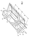
- the fitting In its central region, the fitting generally comprises a female yoke 1 supporting a first pin (not shown) on which the ball joint end of the linear actuator is mounted. In its two end regions, the fitting also comprises a male yoke 2 crossed by a second pin (not shown) supported by the fixed part. This second pin materializes the axis of rotation XX of the control surface.
- the longitudinal axis YY of the first journal and the axis of rotation XX of the control surface are parallel and offset by a distance d from one another.
- Bearings or rings (not shown) are interposed between the yokes 1 and 2 of the fitting and the pins.
- the central point A of the female yoke 1 of the fitting is distant from the central point B of each of the male yokes 2 of the fitting by a distance D, parallel to the axes XX and YY of the pins.
- the distance d between these axes represents the lever arm of the force transmission device materialized by the fitting.
- the force exerted by the linear actuator, associated with the lever arm generates a moment of rotation of the control surface around its axis of rotation.
- XX One thus controls a rotation of the control surface around this axis.
- the distance between the screeds 2 males placed at the ends of the fitting and, by therefore, the distance D are functions of the size of the actuator and the necessary clearances maintenance operations. Otherwise, the size of the actuator depends on its type (EHA- "Electro-Hydraulic Actuator” -, EBHA- “Electro-Backup Hydraulic Actuator “, etc.), its characteristics (stop load, race, etc.) and selected technology (aluminum hydraulic block, titanium, etc.).
- the subject of the invention is a member designed for transmit substantially radial forces between a central region and end regions of said organ, whose original design allows it to withstand very large bending forces to significantly less mass than a journal cylindrical of classic design.
- this result is obtained in using an oriented force transmission member substantially radially with respect to an axis longitudinal of said organ, between a central region and two end regions thereof, said organ being characterized in that it comprises at least three fins distributed around said longitudinal axis and interconnected in said end regions, and at least one pair of star-shaped elements connecting the fins together on either side of said central region.
- the fin structure of the transmission of forces absorbs the majority bending forces, thanks to the high moment of inertia that it generates, for a given section. This design thus optimizes the mass of the structure
- the force transmission organ according to the invention is advantageously carried out in a single room.
- the fins are regularly distributed around the longitudinal axis of said member.
- the force transmission is symmetrical with respect to a median plane perpendicular to the longitudinal axis of said organ.
- all fins may be identical.
- the fins are connected between them, in said end regions, by first two rings and each of the shaped elements star has in its center a second ring, the first and second rings being aligned according to said longitudinal axis.
- the invention also relates to a device transmission of forces comprising a transmission of forces as defined above and a cylindrical rod forming a pin passing through the first and second rings, so as to be tied in bending to the force transmission member, the rod cylindrical supporting a first piece between a pair of star-shaped elements adjacent to the central region and to a second room beyond first rings.
- elements forming bearings are then interposed between the cylindrical rod and each of the first and second rings.
- the stem cylindrical advantageously crosses two sails substantially planar, suitable for being attached to the second room.
- the two sails thus form a female yoke articulated on a male yoke linked to the first part, through the cylindrical rod, and two male yokes articulated on two linked female yokes to a fixed external structure, via a second cylindrical rod forming a journal, centered on an axis of rotation of the second part by relative to the fixed structure, this axis of rotation being parallel to the longitudinal axis of the transmission of efforts.
- the first part is a rod of an actuator to linear control carried by the fixed structure and the second part is an aircraft control surface.
- an aircraft comprises usually a large number of control surfaces.
- This term here means, as in the rest of the text, all elements such as flaps, fins, etc., which are articulated on a fixed part of the aircraft such as the wing, fin, tail or fuselage, for allow the pilot to modify certain flight characteristics such as course, speed, lift, etc.
- Each of the control surfaces can be articulated on the corresponding fixed part by through a transmission device of efforts according to the invention.
- the fixed part is constituted by the wing 12 of the aircraft and the transmission device effort is generally referred to as the reference 14.
- the force transmission device 14 is a structure ensuring both the pivoting mounting of the control surface 10 on the wing 12 and the transmission to the governs 10 of the efforts likely to be applied by a servo-control (not shown) of the airplane.
- the servo usually includes a individual linear actuator, assigned to the control of each control surface.
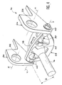
- This linear actuator is housed in the fixed part supporting the control surface, i.e. in wing 12 in the embodiment represented. Only the end of the control rod this actuator is illustrated at 16 in FIG. 4. This end acts on the device 14 of transmission of forces by a ball end 18.
- the transmission device 14 of effort mainly includes a cylindrical rod 20 forming a pin, a transmission member 22 efforts and two sails or plates 24, substantially plans.
- the two sails 24 are generally identical and oriented parallel to each other, in planes substantially perpendicular to the axes X-X and Y-Y. As very schematically illustrates the Figure 3, they are designed to be fixed on the rudder 10, perpendicular to its plane. This fixation may be ensured by any appropriate means, and especially by screwing, riveting, welding, etc.
- Each of the sails has a first hole circular 26 centered on the X-X axis and a second hole circular 28 centered on the Y-Y axis.
- the first holes 26 ensure mounting pivoting of the control surface 10 on the wing 12, by through a cylindrical rod (not shown) forming a pin. More precisely, each of the sails 24 forms a male yoke, which is articulated, by the aforementioned cylindrical rod, on a female yoke (not shown) linked to the wing.
- the second holes 28 receive so rotating end regions of the rod cylindrical 20 forming a trunnion, as illustrated in Figure 4.
- the sails 24 therefore also form a female yoke, which is articulated on the male yoke formed by the ball joint 18, via the cylindrical rod 20.
- the cylindrical rod 20 is arranged coaxially inside the member 22 of transmission of forces, so that these two parts are linked to each other, at least in bending.
- the longitudinal axis common to the - rod cylindrical 20 and to member 22 is the geometric axis Y-Y at which the control rod 16 of the linear actuator acts on the device 24 of transmission of efforts.
- the assembly constituted by the cylindrical rod 20 and the force transmission member 22 forms a double pin, centered on the Y-Y axis.
- This journal double has the function of transmitting to sails 24 the forces applied substantially radially by the rod actuator control 16, in the central region of the cylindrical rod 20 ( Figure 4). More precisely, the double journal formed by the cylindrical rod 20 associated with the force transmission member 22 is designed to transmit efforts to 24 sails applied by the actuator control rod 16 with an optimized, i.e. minimum, mass that is the value of the distance D (figure 4) which separates the axis of the control rod 16 from the median plane of each of the sails 24.
- the force transmission member 22 is made in one piece. It includes three fins 30, identical to each other and regularly distributed around the Y-Y axis. Each of the fins 30 is substantially planar and its median plane passes through the Y-Y axis. In addition, the fins 30 have approximately a C shape and the to each other in the end regions of organ 22. More specifically, the ends of the fins 30 are interconnected by two first rings 32, centered on the Y-Y axis.
- the force transmission member 22 illustrated in Figure 5 also includes a pair of elements 34 in the shape of a star. These elements 34 connect between they fins 30, on either side of a region central of organ 22. More precisely, in the mode illustrated as an example in the figure 5, each of the star-shaped elements 34 comprises at its center a second ring 36, as well as three branches 38 connecting the second ring 36 to each of fins 30.
- the second rings 36 are generally identical to the first rings 32 and centered on the same Y-Y axis.
- the branches 38 are oriented radially with respect to the Y-Y axis and have generally thicknesses identical to those of fins 30. However, branches 38 of thickness different from the fins 30 can also be used.
- the spacing between the shaped elements 34 of star, parallel to the Y-Y axis, is adjusted by so that the distance between the second rings 36 is at least equal to the width of the ball end 18 of the control rod 16 ( Figure 4), which comes lodge between these elements 34.
- the three fins 30 distributed at 120 degrees of each other can be replaced by a greater number of fins, and in particular by four fins distributed at 90 degrees from each other other.
- the number of branches 38 of the 34 elements in star shape is then changed in the same way.
- one or more pairs of elements in star shape are added between the first rings 32 and the pair of elements 34 in the shape of a star adjacent to the central region of organ 22 of transmission of efforts. This change may notably be justified by an increase in the length of the organ 22. Whatever the number of pairs of star-shaped elements entering the constitution of organ 22, this is symmetrical with respect to a median plane perpendicular to the axis YY.
- the height of the fins of a force transmission member 22 to three fins as illustrated in FIG. 5, having a length of 360 mm can be 130 mm.
- the member 22 of force transmission is mounted on the rod cylindrical 20 via elements 40 forming bearings, such as bearing rings or other. These items can however be deleted, without departing from the scope of the invention.
- organ 22 and the rod 20 can optionally be made of a integral, without departing from the scope of the invention.
Landscapes
- Engineering & Computer Science (AREA)
- Aviation & Aerospace Engineering (AREA)
- General Engineering & Computer Science (AREA)
- Mechanical Engineering (AREA)
- Automation & Control Theory (AREA)
- Transmission Devices (AREA)
- Pivots And Pivotal Connections (AREA)
Description
L'invention concerne un organe centré sur un axe longitudinal prédéterminé et conçu pour transmettre des efforts entre une région centrale et des régions d'extrémité dudit organe.The invention relates to a member centered on a predetermined longitudinal axis and designed to transmit efforts between a central region and regions end of said organ.
L'invention concerne également un dispositif comprenant un tel organe, associé à une tige cylindrique formant tourillon, sur laquelle prennent appui deux pièces servant respectivement à appliquer et à recevoir les efforts.The invention also relates to a device comprising such an organ, associated with a rod cylindrical trunnion, on which take support two pieces used respectively to apply and to receive the efforts.
L'invention concerne aussi l'application d'un dispositif de ce type à la transmission des efforts entre un actionneur linéaire monté sur une structure fixe d'aéronef et une gouverne apte à pivoter par rapport à la structure fixe, autour d'un axe de rotation parallèle à l'axe longitudinal de la pièce de transmission d'efforts et décalé par rapport à cet axe. La structure fixe peut notamment être un élément de voilure, de dérive, d'empennage ou de fuselage de l'aéronef.The invention also relates to the application of a device of this type for the transmission of forces between a linear actuator mounted on a structure fixed aircraft and a control surface capable of pivoting by relation to the fixed structure, around an axis of rotation parallel to the longitudinal axis of the workpiece transmission of forces and offset from this axis. The fixed structure can in particular be an element of wing, fin, tail or fuselage the aircraft.
Une gouverne d'aéronef est habituellement articulée sur des éléments structuraux de l'aéronef, considérés comme la partie fixe pour la gouverne mobile, de façon à pouvoir pivoter autour d'un axe de rotation lié à cette partie fixe. Le mouvement de rotation de la gouverne est piloté par une servocommande, matérialisée par un actionneur linéaire porté par la partie fixe de l'aéronef. L'actionneur linéaire comprend un embout à rotule. Celui-ci agit sur la gouverne par l'intermédiaire de ferrures fixées sur la gouverne au moyen de vis, de rivets, etc.. Les ferrures assurent également la rotation de la gouverne par rapport à la partie fixe de l'aéronef.An aircraft control surface is usually articulated on structural elements of the aircraft, considered as the fixed part for the control mobile, so that it can pivot around an axis of rotation linked to this fixed part. The movement of rotation of the control surface is controlled by a servo control, materialized by a linear actuator carried by the fixed part of the aircraft. The actuator linear includes a ball end. This acts on the control surface by means of fittings fixed on the control surface by means of screws, rivets, etc. fittings also rotate the control surface relative to the fixed part of the aircraft.
Une ferrure est connue de US-A-3,756,089, qui montre toutes les caractéristiques du préambule de la revendication indépentante.A fitting is known from US-A-3,756,089, which shows all the features of the preamble of the independent claim.
Une autre ferrure illustrant l'état de la technique est représentée schématiquement, en perspective, sur la figure 1 des dessins annexés.Another fitting illustrating the state of the art is shown schematically, in perspective, on the Figure 1 of the accompanying drawings.
Dans sa région centrale, la ferrure comprend
généralement une chape femelle 1 supportant un premier
tourillon (non représenté) sur lequel est monté
l'embout à rotule de l'actionneur linéaire. Dans ses
deux régions d'extrémité, la ferrure comprend également
une chape mâle 2 traversée par un deuxième tourillon
(non représenté) supporté par la partie fixe. Ce
deuxième tourillon matérialise l'axe de rotation X-X de
la gouverne. L'axe longitudinal Y-Y du premier
tourillon et l'axe de rotation X-X de la gouverne sont
parallèles et décalés d'une distance d l'un par rapport
à l'autre. Des roulements ou des bagues (non
représentés) sont interposés entre les chapes 1 et 2 de
la ferrure et les tourillons.In its central region, the fitting generally comprises a female yoke 1 supporting a first pin (not shown) on which the ball joint end of the linear actuator is mounted. In its two end regions, the fitting also comprises a
Dans cet agencement connu, le point central A
de la chape femelle 1 de la ferrure est distant du
point central B de chacune des chapes mâles 2 de la
ferrure d'une distance D, parallèlement aux axes X-X et
Y-Y des tourillons. La distance d entre ces axes
représente le bras de levier du dispositif de
transmission d'efforts matérialisé par la ferrure.
L'effort exercé par l'actionneur linéaire, associé au
bras de levier, engendre un moment de rotation de la
gouverne autour de son axe de rotation.X-X On commande
ainsi une rotation de la gouverne autour de cet axe.In this known arrangement, the central point A of the female yoke 1 of the fitting is distant from the central point B of each of the
Lors de l'actionnement de la gouverne, une
grosse partie des efforts exercés par l'actionneur
linéaire transite de la chape femelle 1 placée dans la
partie centrale de la ferrure jusqu'aux chapes mâles 2
placées dans les parties d'extrémité de la ferrure, par
l'intermédiaire des structures de la ferrure et de la
gouverne. Les contraintes et les déformées provoquées
par l'application de ces efforts sur la structure de la
ferrure sont proportionnelles à la distance D qui
sépare la chape femelle 1 de chacune des chapes mâles 2
de la ferrure, parallèlement aux axes X-X et Y-Y des
tourillons.When operating the control surface, a
large part of the efforts exerted by the actuator
linear transit of the female yoke 1 placed in the
central part of the fitting to the
Dans la pratique, la distance entre les chapes
mâles 2 placées aux extrémités de la ferrure et, par
conséquent, la distance D, sont fonctions de
l'encombrement de l'actionneur et des jeux nécessaires
aux opérations de maintenance. Par ailleurs,
l'encombrement de l'actionneur est fonction de son type
(EHA-"Electro-Hydraulic Actuator"-, EBHA-"Electro-Backup
Hydraulic Actuator", etc.), de ses
caractéristiques (charge d'arrêt, course, etc.) et de
la technologie retenue (bloc hydraulique en aluminium,
en titane, etc.).In practice, the distance between the
Lorsque l'encombrement de la servocommande augmente, il est donc nécessaire d'augmenter la distance D entre la chape femelle 1 liée à la partie centrale de la ferrure et les chapes mâles 2 placées aux extrémités de celle-ci. Cela impose une forte augmentation de la masse de la ferrure afin de limiter les contraintes et les déformations en son sein. Toutefois, une telle augmentation de masse est généralement incompatible avec les performances requises pour l'aéronef.When the size of the servo drive increases, so it is necessary to increase the distance D between the female yoke 1 linked to the part central of the fitting and the 2 male clevis placed at the ends of it. This imposes a strong increase in the mass of the fitting in order to limit the constraints and the deformations within it. However, such an increase in mass is generally incompatible with performance required for the aircraft.
L'invention a pour objet un organe conçu pour transmettre des efforts sensiblement radiaux entre une région centrale et des régions d'extrémité dudit organe, dont la conception originale lui permet de supporter des efforts de flexion très importants pour une masse sensiblement moindre qu'un tourillon cylindrique de conception classique.The subject of the invention is a member designed for transmit substantially radial forces between a central region and end regions of said organ, whose original design allows it to withstand very large bending forces to significantly less mass than a journal cylindrical of classic design.
Selon l'invention, ce résultat est obtenu en utilisant un organe de transmission d'efforts orientés sensiblement radialement par rapport à un axe longitudinal dudit organe, entre une région centrale et deux régions d'extrémité de celui-ci, ledit organe étant caractérisé en ce qu'il comprend au moins trois ailettes réparties autour dudit axe longitudinal et reliées entre elles dans lesdites régions d'extrémité, et au moins une paire d'éléments en forme d'étoile reliant entre elles les ailettes de part et d'autre de ladite région centrale.According to the invention, this result is obtained in using an oriented force transmission member substantially radially with respect to an axis longitudinal of said organ, between a central region and two end regions thereof, said organ being characterized in that it comprises at least three fins distributed around said longitudinal axis and interconnected in said end regions, and at least one pair of star-shaped elements connecting the fins together on either side of said central region.
La structure à ailettes de l'organe de transmission d'efforts permet d'absorber la majorité des efforts de flexion, grâce au fort moment d'inertie qu'elle engendre, pour une section donnée. Cette conception permet ainsi d'optimiser la masse de la structure The fin structure of the transmission of forces absorbs the majority bending forces, thanks to the high moment of inertia that it generates, for a given section. This design thus optimizes the mass of the structure
L'organe de transmission d'efforts selon l'invention est réalisé avantageusement en une seule pièce.The force transmission organ according to the invention is advantageously carried out in a single room.
Dans un mode de réalisation préféré de l'invention, les ailettes sont régulièrement réparties autour de l'axe longitudinal dudit organe.In a preferred embodiment of the invention, the fins are regularly distributed around the longitudinal axis of said member.
Dans ce même mode de réalisation, l'organe de transmission d'efforts est symétrique par rapport à un plan médian perpendiculaire à l'axe longitudinal dudit organe.In this same embodiment, the force transmission is symmetrical with respect to a median plane perpendicular to the longitudinal axis of said organ.
Pour simplifier la fabrication, toutes les ailettes peuvent être identiques.To simplify manufacturing, all fins may be identical.
Avantageusement, les ailettes sont reliées entre elles, dans lesdites régions d'extrémité, par deux premières bagues et chacun des éléments en forme d'étoile comporte en son centre une deuxième bague, les premières et deuxièmes bagues étant alignées selon ledit axe longitudinal.Advantageously, the fins are connected between them, in said end regions, by first two rings and each of the shaped elements star has in its center a second ring, the first and second rings being aligned according to said longitudinal axis.
L'invention a aussi pour objet un dispositif de transmission d'efforts comprenant un organe de transmission d'efforts tel que défini ci-dessus et une tige cylindrique formant tourillon traversant les premières et deuxièmes bagues, de façon à être liée en flexion à l'organe de transmission d'efforts, la tige cylindrique servant d'appui à une première pièce entre une paire d'éléments en forme d'étoile adjacente à la région centrale et à une deuxième pièce au-delà des premières bagues.The invention also relates to a device transmission of forces comprising a transmission of forces as defined above and a cylindrical rod forming a pin passing through the first and second rings, so as to be tied in bending to the force transmission member, the rod cylindrical supporting a first piece between a pair of star-shaped elements adjacent to the central region and to a second room beyond first rings.
Avantageusement, des éléments formant paliers sont alors interposés entre la tige cylindrique et chacune des première et deuxièmes bagues. Advantageously, elements forming bearings are then interposed between the cylindrical rod and each of the first and second rings.
Au-delà des premières bagues, la tige cylindrique traverse avantageusement deux voiles sensiblement plans, aptes à être fixés à la deuxième pièce. Les deux voiles forment ainsi une chape femelle articulée sur une chape mâle liée à la première pièce, par l'intermédiaire de la tige cylindrique, et deux chapes mâles articulées sur deux chapes femelles liées à une structure extérieure fixe, par l'intermédiaire d'une deuxième tige cylindrique formant tourillon, centrée sur un axe de rotation de la deuxième pièce par rapport à la structure fixe, cet axe de rotation étant parallèle à l'axe longitudinal de l'organe de transmission d'efforts.Beyond the first rings, the stem cylindrical advantageously crosses two sails substantially planar, suitable for being attached to the second room. The two sails thus form a female yoke articulated on a male yoke linked to the first part, through the cylindrical rod, and two male yokes articulated on two linked female yokes to a fixed external structure, via a second cylindrical rod forming a journal, centered on an axis of rotation of the second part by relative to the fixed structure, this axis of rotation being parallel to the longitudinal axis of the transmission of efforts.
Dans une application préférée de l'invention, la première pièce est une tige d'un actionneur à commande linéaire porté par la structure fixe et la deuxième pièce est une gouverne d'aéronef.In a preferred application of the invention, the first part is a rod of an actuator to linear control carried by the fixed structure and the second part is an aircraft control surface.
On décrira à présent, à titre d'exemple non limitatif, un mode de réalisation préféré de l'invention, en se référant aux dessins annexés, dans lesquels :
- la figure 1, déjà décrite, est une vue en perspective d'une ferrure de montage de gouverne d'aéronef conforme à l'art antérieur ;
- la figure 2 représente schématiquement, en vue de dessus, une voilure d'aéronef sur laquelle sont articulées des gouvernes susceptibles d'être actionnées par l'intermédiaire de dispositifs de transmission d'efforts conformes à l'invention ;
- la figure 3 est une vue en coupe, à plus grande échelle, selon la ligne III-III de la figure 2 ;
- - la figure 4 est une vue en perspective d'un dispositif de transmission d'efforts conforme à l'invention ; et
- la figuré 5 est une vue en perspective d'un organe de transmission d'efforts formant une partie du dispositif de la figure 4.
- Figure 1, already described, is a perspective view of an aircraft control surface mounting fitting according to the prior art;
- FIG. 2 schematically represents, in top view, an aircraft wing on which hinged control surfaces are capable of being actuated by means of force transmission devices in accordance with the invention;
- Figure 3 is a sectional view, on a larger scale, along the line III-III of Figure 2;
- - Figure 4 is a perspective view of a force transmission device according to the invention; and
- FIG. 5 is a perspective view of a force transmission member forming part of the device in FIG. 4.
Comme l'illustre la figure 2 dans le cas particulier d'une aile d'avion, un aéronef comporte habituellement un grand nombre de gouvernes. Ce terme désigne ici, comme dans l'ensemble du texte, tous les éléments de type volets, ailerons, etc., qui sont articulés sur une partie fixe de l'aéronef telle que la voilure, la dérive, l'empennage ou le fuselage, pour permettre au pilote de modifier certaines caractéristiques de vol telles que le cap, la vitesse, la portance, etc..As illustrated in Figure 2 in the case particular of an airplane wing, an aircraft comprises usually a large number of control surfaces. This term here means, as in the rest of the text, all elements such as flaps, fins, etc., which are articulated on a fixed part of the aircraft such as the wing, fin, tail or fuselage, for allow the pilot to modify certain flight characteristics such as course, speed, lift, etc.
Chacune des gouvernes, telles que celle qui
est désignée par la référence 10 sur la figure 2, peut
être articulée sur la partie fixe correspondante par
l'intermédiaire d'un dispositif de transmission
d'efforts conforme à l'invention. Dans le mode de
réalisation représenté à titre d'exemple sur les
figures 2 à 5, la partie fixe est constituée par l'aile
12 de l'avion et le dispositif de transmission
d'efforts est désigné de façon générale par la
référence 14.Each of the control surfaces, such as that which
is designated by the
Le dispositif de transmission d'efforts 14 est
une structure assurant à la fois le montage pivotant de
la gouverne 10 sur l'aile 12 et la transmission à la
gouverne 10 des efforts susceptibles d'être appliqués
par une servocommande (non représentée) de l'avion.The
La servocommande comprend habituellement un
actionneur linéaire individuel, affecté à la commande
de chaque gouverne. Cet actionneur linéaire est logé
dans la partie fixe supportant la gouverne, c'est-à-dire
dans l'aile 12 dans le mode de réalisation
représenté. Seule l'extrémité de la tige de commande de
cet actionneur est illustrée en 16 sur la figure 4.
Cette extrémité agit sur le dispositif 14 de
transmission d'efforts par un embout à rotule 18.The servo usually includes a
individual linear actuator, assigned to the control
of each control surface. This linear actuator is housed
in the fixed part supporting the control surface, i.e.
in
De façon plus précise, si l'on désigne par X-X
l'axe de rotation de la gouverne 10 par rapport à
l'aile 12, la tige de commande 16 de l'actionneur
linéaire agit sur le dispositif 14 de transmission
d'efforts par un axe géométrique Y-Y parallèle à l'axe
X-X, mais décalé d'une distance d par rapport à cet axe
(figure 4).More precisely, if XX designates the axis of rotation of the
Dans le mode de réalisation représenté sur les
figures 2 à 5, le dispositif 14 de transmission
d'efforts comprend principalement une tige cylindrique
20 formant tourillon, un organe 22 de transmission
d'efforts et deux voiles ou plaques 24, sensiblement
plans.In the embodiment shown in the
Figures 2 to 5, the
Les deux voiles 24 sont généralement
identiques et orientés parallèlement l'un à l'autre,
dans des plans sensiblement perpendiculaires aux axes
X-X et Y-Y. Comme l'illustre très schématiquement la
figure 3, ils sont prévus pour être fixés sur la
gouverne 10, perpendiculairement à son plan. Cette
fixation peut être assurée par tout moyen approprié, et
notamment par vissage, rivetage, soudage, etc..The two sails 24 are generally
identical and oriented parallel to each other,
in planes substantially perpendicular to the axes
X-X and Y-Y. As very schematically illustrates the
Figure 3, they are designed to be fixed on the
Chacun des voiles comporte un premier trou circulaire 26 centré sur l'axe X-X et un deuxième trou circulaire 28 centré sur l'axe Y-Y.Each of the sails has a first hole circular 26 centered on the X-X axis and a second hole circular 28 centered on the Y-Y axis.
Les premiers trous 26 assurent le montage
pivotant de la gouverne 10 sur l'aile 12, par
l'intermédiaire d'une tige cylindrique (non
représentée) formant tourillon. Plus précisément,
chacun des voiles 24 forme une chape mâle, qui est
articulée, par la tige cylindrique précitée, sur une
chape femelle (non représentée) liée à l'aile.The
Les deuxièmes trous 28 reçoivent de façon
tournante des régions d'extrémité de la tige
cylindrique 20 formant tourillon, comme l'illustre la
figure 4. Les voiles 24 forment donc également une
chape femelle, qui est articulée sur la chape mâle
formée par l'embout à rotule 18, par l'intermédiaire de
la tige cylindrique 20.The
Il est à noter que l'écartement entre les
voiles 24 augmente avec l'encombrement de l'actionneur.
Toutefois, l'utilisation de l'organe 22 de transmission
d'efforts conforme à l'invention permet de limiter
considérablement l'augmentation de masse entraínée par
un accroissement de l'écartement des voiles, comme on
le comprendra mieux par la suite.Note that the spacing between the
La tige cylindrique 20 est disposée
coaxialement à l'intérieur de l'organe 22 de
transmission d'efforts, de telle sorte que ces deux
pièces soient liées l'une à l'autre, au moins en
flexion. L'axe longitudinal commun à la - tige
cylindrique 20 et à l'organe 22 est l'axe géométrique
Y-Y au niveau duquel la tige de commande 16 de
l'actionneur linéaire agit sur le dispositif 24 de
transmission d'efforts.The
Dans cet agencement propre à l'invention,
l'ensemble constitué par la tige cylindrique 20 et
l'organe 22 de transmission d'efforts forme un
tourillon double, centré sur l'axe Y-Y. Ce tourillon
double a pour fonction de transmettre aux voiles 24 les
efforts appliqués sensiblement radialement par la tige
de commande 16 de l'actionneur, dans la région centrale
de la tige cylindrique 20 (figure 4). Plus précisément,
le tourillon double formé par la tige cylindrique 20
associée à l'organe 22 de transmission d'efforts est
conçu pour transmettre aux voiles 24 les efforts
appliqués par la tige de commande 16 de l'actionneur
avec une masse optimisée, c'est-à-dire minimale, quelle
que soit la valeur de la distance D (figure 4) qui
sépare l'axe de la tige de commande 16 du plan médian
de chacun des voiles 24.In this arrangement specific to the invention,
the assembly constituted by the
Pour parvenir à ce résultat, on utilise un
organe 22 de transmission d'efforts dont la structure
va à présent être décrite en détails en se référant à
la figure 5.To achieve this, we use a
Dans le mode de réalisation représenté sur la
figure 5, l'organe 22 de transmission d'efforts est
réalisé en une seule pièce. Il comprend trois ailettes
30, identiques les unes aux autres et régulièrement
réparties autour de l'axe Y-Y. Chacune des ailettes 30
est sensiblement plane et son plan médian passe par
l'axe Y-Y. De plus, les ailettes 30 présentent
approximativement une forme en C et sont reliées les
unes aux autres dans les régions d'extrémité de
l'organe 22. Plus précisément, les extrémités des
ailettes 30 sont reliées entre elles par deux premières
bagues 32, centrées sur l'axe Y-Y.In the embodiment shown in the
Figure 5, the
L'organe 22 de transmission d'efforts illustré
sur la figure 5 comprend également une paire d'éléments
34 en forme d'étoile. Ces éléments 34 relient entre
elles les ailettes 30, de part et d'autre d'une région
centrale de l'organe 22. Plus précisément, dans le mode
de réalisation illustré à titre d'exemple sur la figure
5, chacun des éléments 34 en forme d'étoile comprend en
son centre une deuxième bague 36, ainsi que trois
branches 38 reliant la deuxième bague 36 à chacune des
ailettes 30. Les deuxièmes bagues 36 sont généralement
identiques aux premières bagues 32 et centrées sur le
même axe Y-Y. Les branches 38 sont orientées
radialement par rapport à l'axe Y-Y et présentent
généralement des épaisseurs identiques à celles des
ailettes 30. Toutefois, des branches 38 d'épaisseurs
différentes de celles des ailettes 30 peuvent aussi
être utilisées.The
L'écartement entre les éléments 34 en forme
d'étoile, parallèlement à l'axe Y-Y, est ajusté de
façon que la distance entre les deuxièmes bagues 36
soit au moins égale à la largeur de l'embout à rotule
18 de la tige de commande 16 (figure 4), qui vient se
loger entre ces éléments 34.The spacing between the
Dans des variantes de réalisation non
représentées, les trois ailettes 30 réparties à 120
degrés les unes des autres peuvent être remplacées par
un plus grand nombre d'ailettes, et notamment par
quatre ailettes réparties à 90 degrés les unes des
autres. Le nombre de branches 38 des éléments 34 en
forme d'étoile est alors modifié de la même façon.In variant embodiments not
shown, the three
Dans d'autres variantes de réalisation non
représentées, une ou plusieurs paires d'éléments en
forme d'étoiles sont ajoutées entre les premières
bagues 32 et la paire d'éléments 34 en forme d'étoile
adjacente à la région centrale de l'organe 22 de
transmission d'efforts. Cette modification peut
notamment être justifiée par une augmentation de la
longueur de l'organe 22. Quel que soit le nombre de
paires d'éléments en forme d'étoile entrant dans la
constitution de l'organe 22, celui-ci est symétrique
par rapport à un plan médian perpendiculaire à l'axe
Y-Y.In other variant embodiments not
represented, one or more pairs of elements in
star shape are added between the
A titre d'exemple et de façon nullement
limitative de la portée de l'invention, la hauteur des
ailettes d'un organe 22 de transmission d'efforts à
trois ailettes tel qu'illustré sur la figure 5,
présentant une longueur de 360 mm, peut être de 130 mm.By way of example and in no way
limiting the scope of the invention, the height of the
fins of a
Comme le montre la figure 4, l'organe 22 de
transmission d'efforts est monté sur la tige
cylindrique 20 par l'intermédiaire d'éléments 40
formant paliers, tels que des bagues de roulement ou
autres. Ces éléments peuvent toutefois être supprimés,
sans sortir du cadre de l'invention.As shown in Figure 4, the
Dans l'assemblage illustré sur la figure 4,
lorsque l'actionneur linéaire est mis en oeuvre, un
effort est exercé sur la région centrale de la tige
cylindrique 20, perpendiculairement à son axe
longitudinal Y-Y, pour commander le pivotement de la
gouverne 10 autour de son axe de rotation X-X, dans
l'un ou l'autre sens.In the assembly illustrated in Figure 4,
when the linear actuator is used, a
force is exerted on the central region of the rod
cylindrical 20, perpendicular to its axis
longitudinal Y-Y, to control the pivoting of the
Grâce à la présence de l'organe 22 de
transmission d'efforts autour de la tige cylindrique
20, cet effort est transmis intégralement aux voiles 24
liés à la gouverne, au moyen d'un dispositif présentant
une masse minimale, quelle que soit la distance D qui
sépare les régions centrale et d'extrémité de la tige
20. En effet, la structure à ailettes de l'organe 22 de
transmission d'efforts engendre un fort moment
d'inertie, qui lui permet d'absorber la majorité des
efforts de flexion. De plus, ce moment d'inertie est
constant par rapport à son axe Y-Y, pour une section
donnée, quelle que soit sa position angulaire.Thanks to the presence of
La présence de l'organe 22 de transmission
d'efforts, de conception optimisée, autour de la tige
cylindrique 20, permet de conserver pour celle-ci un
diamètre proche de celui qui serait utilisé avec une
ferrure d'articulation classique comprenant une chape
femelle encadrant directement l'embout à rotule 18. Par
conséquent la masse globale du dispositif est
optimisée, quelle que soit la taille de l'actionneur
linéaire qui commande le volet.The presence of the
Bien que l'ensemble de la description qui précède concerne la commande de gouvernes d'aéronefs, il est important de noter que l'invention n'est en aucun cas limitée à cette application. En effet, l'organe et le dispositif de transmission d'efforts qui ont été décrits, ainsi que les différentes variantes précédemment mentionnées, peuvent être utilisés à chaque fois qu'un effort sensiblement radial doit être transmis entre la région centrale et les régions d'extrémité du dispositif. Cette situation se retrouve dans de nombreux mécanismes et dans des domaines techniques très variés tels que les industries aéronautique et spatiale, l'industrie automobile, les machines-outils, les machines agricoles, etc..Although the entire description which above relates to the control of aircraft control surfaces, it is important to note that the invention is not in no case limited to this application. Indeed, the organ and the force transmission device which have been described, as well as the different variants previously mentioned, can be used at whenever a substantially radial force must be transmitted between the central region and the regions end of the device. This situation is found in many mechanisms and in areas very varied techniques such as industries aeronautics and space, the automotive industry, machine tools, agricultural machinery, etc.
Il est à noter, par ailleurs, que l'organe 22
et la tige 20 peuvent éventuellement être réalisés d'un
seul tenant, sans sortir du cadre de l'invention.It should also be noted that
Claims (10)
- Device (22) for transmission of forces in approximately the radial direction from a longitudinal (Y-Y) axis of the said device, between a central region and two end regions of the device, the said device (22) being characterized in that it comprises at least three ribs (30) distributed around the said longitudinal axis (Y-Y) and connected to each other in the said end regions, and at least one pair of elements (34) in the shape of a star connecting the ribs (30) on each side of the said central region.
- Force transmission device according to claim 1, in which the said device (22) is made in a single part.
- Force transmission device according to either of claims 1 or 2, in which the ribs (30) are uniformly distributed around the said longitudinal (Y-Y) axis.
- Force transmission device according to any one of claims 1 to 3, in which the said device (22) is symmetric about a median plane perpendicular to the said longitudinal (Y-Y) axis.
- Force transmission device according to any one of claims 1 to 4, in which all ribs (30) are identical.
- Force transmission device according to any one of claims 1 to 5, in which the ribs (30) are connected to each other in the said end regions by two first rings (32) and each of the star shaped elements (34) comprises a second ring (36) at its center, the first and second rings (32, 36) along the said longitudinal (Y-Y) axis.
- Force transmission mechanism comprising a force transmission device (22) according to claim 6 and a cylindrical rod (20) acting as a pivot pin passing through the first and second rings (32, 36) so that it is fixed in bending to the force transmission device, the cylindrical rod (20) acting in bearing for a first part (16) between a pair of star shaped elements (34) adjacent to the central region and a second part (10) beyond the first rings.
- Force transmission mechanism according to claim 7, in which the elements (40) forming bearings are inserted between the cylindrical rod (20) and each of the first and second rings (32, 36).
- Force transmission mechanism according to either of claims 7 or 8, in which the cylindrical rod (20) passes through two approximately plane webs (24), that can be fixed to the second part, beyond the first rings (32), the two webs being designed to be fixed to the second part (10), the said webs forming a double eye plate articulated onto a single eye plate (18) connected to the first part (16) through the cylindrical rod (20), and forming two single eye plates articulated on two double eye plates linked to a fixed external structure through a second cylindrical rods acting as a pivot pin centered on an axis of rotation (X-X) of the second part (10) with respect to the fixed structure, this axis of rotation (X-X) being parallel to the said longitudinal (Y-Y) axis.
- Force transmission mechanism according to any one of claims 7 to 9, in which the first part is a rod (16) of an actuator with linear control supported by the fixed structure and the second part is an aircraft control surface (10).
Applications Claiming Priority (2)
| Application Number | Priority Date | Filing Date | Title |
|---|---|---|---|
| FR0013736A FR2815933B1 (en) | 2000-10-26 | 2000-10-26 | BODY AND DEVICE FOR TRANSMISSION OF RADIAL EFFORTS BETWEEN CENTRAL AND END REGIONS OF THIS BODY |
| FR0013736 | 2000-10-26 |
Publications (2)
| Publication Number | Publication Date |
|---|---|
| EP1201537A1 EP1201537A1 (en) | 2002-05-02 |
| EP1201537B1 true EP1201537B1 (en) | 2003-08-13 |
Family
ID=8855760
Family Applications (1)
| Application Number | Title | Priority Date | Filing Date |
|---|---|---|---|
| EP01402771A Expired - Lifetime EP1201537B1 (en) | 2000-10-26 | 2001-10-25 | Aircraft control surface actuating linkage |
Country Status (5)
| Country | Link |
|---|---|
| US (1) | US6530544B2 (en) |
| EP (1) | EP1201537B1 (en) |
| CA (1) | CA2360889C (en) |
| DE (1) | DE60100589T2 (en) |
| FR (1) | FR2815933B1 (en) |
Families Citing this family (12)
| Publication number | Priority date | Publication date | Assignee | Title |
|---|---|---|---|---|
| AT409482B (en) * | 2001-01-26 | 2002-08-26 | Fischer Adv Components Gmbh | DEVICE FOR CONNECTING MOVABLE PARTS TO STRUCTURAL COMPONENTS OF AIRCRAFT OR. DGL. |
| ES2315109B1 (en) * | 2006-06-30 | 2010-01-12 | Airbus España, S.L. | HARDWARE WITH TORSION DRAWER, OF PLASTIC MATERIAL REINFORCED WITH CARBON FIBERS, TO COUPLING A DRIVE / SPINDLE MOTOR ASSEMBLY FOR THE TRIMADO OF A HORIZONTAL STABILIZER OF AN AIRCRAFT. |
| DE102007011618B4 (en) * | 2007-01-22 | 2012-04-26 | Airbus Operations Gmbh | Crash paddle for reinforcing a primary fuselage structure of an aircraft |
| FR2922280B1 (en) * | 2007-10-11 | 2010-02-26 | Airbus France | ASSEMBLY METHOD FOR A FATIGUE RESISTANT MECHANICAL JOINT |
| GB0808349D0 (en) * | 2008-05-09 | 2008-06-18 | Airbus Uk Ltd | Spoiler deployment mechanism |
| US8118260B2 (en) * | 2008-10-31 | 2012-02-21 | Airbus Operations S.L. | Fitting for trimming a horizontal stabilizer of an aircraft |
| ES2364109B1 (en) * | 2008-11-27 | 2012-07-04 | Airbus Operations, S.L. | A TRIMADO FRONT HARDWARE AND ITS ASSEMBLY TO THE UNION AT TRACTION OF THE TWO SIDE DRAWERS OF THE HORIZONTAL STABILIZER OF AN AIRCRAFT |
| DE102010006447A1 (en) | 2010-02-01 | 2011-08-04 | Airbus Operations GmbH, 21129 | connecting device |
| EP2571758A4 (en) * | 2010-05-21 | 2017-09-13 | Airbus SAS | Droop panel linkage |
| US20150360768A1 (en) * | 2014-06-12 | 2015-12-17 | Troy A. Woodland | Mounting assembly for fully automatic slat |
| RU2630565C2 (en) * | 2015-12-28 | 2017-09-11 | Российская Федерация, от имени которой выступает Министерство обороны Российской Федерации | Connectivity device of space vehicle separated elements |
| CN114750929A (en) * | 2022-04-26 | 2022-07-15 | 北京北航天宇长鹰无人机科技有限公司 | Unmanned aerial vehicle aileron structure and unmanned aerial vehicle |
Family Cites Families (7)
| Publication number | Priority date | Publication date | Assignee | Title |
|---|---|---|---|---|
| US2246116A (en) * | 1937-10-28 | 1941-06-17 | Messerschmitt Boelkow Blohm | Airplane wing structure |
| US2779555A (en) * | 1952-07-05 | 1957-01-29 | Lockheed Aircraft Corp | Wing flap actuating mechanism |
| US3756089A (en) * | 1971-04-15 | 1973-09-04 | H Haladay | Linkage for narrow environments |
| IT947728B (en) * | 1972-02-19 | 1973-05-30 | Semel Spa | PIVOTING DEVICE WITHOUT CLEARANCE IN PARTICULAR FOR MEASURING INSTRUMENTS |
| EP0007108B1 (en) * | 1978-07-18 | 1983-04-13 | Nippon Telegraph and Telephone Public Corporation | A method of manufacturing a diffraction grating structure |
| US4497461A (en) * | 1982-09-24 | 1985-02-05 | The Boeing Company | Snubbing apparatus for an aircraft control surface actuator |
| US6270039B1 (en) * | 1999-10-12 | 2001-08-07 | Patria Finavicomp Oy | Hinge for movable control surfaces in an aircraft and a connecting piece to be used with such a hinge |
-
2000
- 2000-10-26 FR FR0013736A patent/FR2815933B1/en not_active Expired - Fee Related
-
2001
- 2001-10-18 US US09/978,555 patent/US6530544B2/en not_active Expired - Lifetime
- 2001-10-23 CA CA002360889A patent/CA2360889C/en not_active Expired - Fee Related
- 2001-10-25 DE DE60100589T patent/DE60100589T2/en not_active Expired - Lifetime
- 2001-10-25 EP EP01402771A patent/EP1201537B1/en not_active Expired - Lifetime
Also Published As
| Publication number | Publication date |
|---|---|
| DE60100589T2 (en) | 2004-06-24 |
| FR2815933B1 (en) | 2003-01-24 |
| FR2815933A1 (en) | 2002-05-03 |
| CA2360889A1 (en) | 2002-04-26 |
| EP1201537A1 (en) | 2002-05-02 |
| US20020125369A1 (en) | 2002-09-12 |
| CA2360889C (en) | 2009-08-04 |
| DE60100589D1 (en) | 2003-09-18 |
| US6530544B2 (en) | 2003-03-11 |
Similar Documents
| Publication | Publication Date | Title |
|---|---|---|
| EP1201537B1 (en) | Aircraft control surface actuating linkage | |
| EP2858897B1 (en) | Joystick for controlling an aircraft | |
| CA3026069C (en) | Maneuver process for aircraft landing gear between a deployed position and a retracted position | |
| FR2902454A1 (en) | TURBOMACHINE STATOR COMPRISING A FLOOR OF ADJUSTERS ADJUSTED BY A ROTATING CROWN WITH AUTOMATIC CENTERING | |
| FR2768996A1 (en) | Helicopter rotor blade pitch control swash plate | |
| FR2768997A1 (en) | Helicopter rotor blade pitch control swash plate with non rotating star stop peg | |
| EP0457646B1 (en) | Swashplate device supported on mounts decoupled in pitch and roll, for the rotor blades pitch control of a rotorcraft | |
| EP0742144B1 (en) | Rotor with a device for damping lead-lag motion of the rotor blades | |
| CA2308717C (en) | Structure for attaching a landing gear to an aircraft fuselage | |
| EP0718187B1 (en) | Bidirectional vibration absorbing suspension device for a helicopter rotor | |
| FR2797248A1 (en) | METHOD AND APPARATUS FOR DETECTING A PRELOAD IN A ROTOR STOPPING DEVICE OF A TILTING ROTOR AIRCRAFT | |
| EP0757955A1 (en) | System for controlling an aerodynamic surface hinged on a vehicle structure | |
| FR2669857A1 (en) | DEVICE FOR LOCKING A STEERING WHEEL SUPPORT. | |
| EP0050079B1 (en) | Toothed unlocking device for a safety joint | |
| EP0033044B1 (en) | Jet-propulsion unit nozzle | |
| EP0126671B1 (en) | Flexible mounting system between a device and a planar support, particularly a high precision instrument on a spacecraft | |
| EP3381800B1 (en) | Rotary-wing aircraft including a set of swashplates and two drive scissors | |
| EP0549455A1 (en) | Cylindric elastomeric bearing system with large angular deflection | |
| EP3847096B1 (en) | Aircraft flight control device | |
| EP3467612B1 (en) | Device for generating force sensation, by friction, for a flight control system of an aircraft | |
| WO2000045040A1 (en) | System for activating an adjustable tube by means of an elastic ring for a thrust nozzle | |
| FR3039132A1 (en) | HORIZONTAL AXIS PROPELLER PROPELLER ASSEMBLY FOR AIRCRAFT | |
| CH349457A (en) | Process for obtaining a mechanical assembly and a mechanical assembly obtained by means of this process | |
| FR2797430A1 (en) | TILTING ROTOR AIRCRAFT HAVING A DOWN TURN STOP ASSEMBLY | |
| EP2365369B1 (en) | System for actuating movable elements with dynamically compensated and opposed relative movements |
Legal Events
| Date | Code | Title | Description |
|---|---|---|---|
| PUAI | Public reference made under article 153(3) epc to a published international application that has entered the european phase |
Free format text: ORIGINAL CODE: 0009012 |
|
| AK | Designated contracting states |
Kind code of ref document: A1 Designated state(s): AT BE CH CY DE DK ES FI FR GB GR IE IT LI LU MC NL PT SE TR Kind code of ref document: A1 Designated state(s): DE FI GB |
|
| AX | Request for extension of the european patent |
Free format text: AL;LT;LV;MK;RO;SI |
|
| 17P | Request for examination filed |
Effective date: 20021005 |
|
| AKX | Designation fees paid |
Free format text: DE FI GB |
|
| GRAH | Despatch of communication of intention to grant a patent |
Free format text: ORIGINAL CODE: EPIDOS IGRA |
|
| GRAH | Despatch of communication of intention to grant a patent |
Free format text: ORIGINAL CODE: EPIDOS IGRA |
|
| GRAA | (expected) grant |
Free format text: ORIGINAL CODE: 0009210 |
|
| AK | Designated contracting states |
Designated state(s): DE FI GB |
|
| REG | Reference to a national code |
Ref country code: GB Ref legal event code: FG4D Free format text: NOT ENGLISH |
|
| REG | Reference to a national code |
Ref country code: IE Ref legal event code: FG4D Free format text: FRENCH |
|
| REF | Corresponds to: |
Ref document number: 60100589 Country of ref document: DE Date of ref document: 20030918 Kind code of ref document: P |
|
| GBT | Gb: translation of ep patent filed (gb section 77(6)(a)/1977) |
Effective date: 20031117 |
|
| REG | Reference to a national code |
Ref country code: IE Ref legal event code: FD4D |
|
| PLBE | No opposition filed within time limit |
Free format text: ORIGINAL CODE: 0009261 |
|
| STAA | Information on the status of an ep patent application or granted ep patent |
Free format text: STATUS: NO OPPOSITION FILED WITHIN TIME LIMIT |
|
| 26N | No opposition filed |
Effective date: 20040514 |
|
| REG | Reference to a national code |
Ref country code: GB Ref legal event code: 732E Free format text: REGISTERED BETWEEN 20110721 AND 20110727 |
|
| REG | Reference to a national code |
Ref country code: DE Ref legal event code: R082 Ref document number: 60100589 Country of ref document: DE Representative=s name: HENKEL, BREUER & PARTNER, DE |
|
| REG | Reference to a national code |
Ref country code: DE Ref legal event code: R081 Ref document number: 60100589 Country of ref document: DE Owner name: AIRBUS OPERATIONS SAS, FR Free format text: FORMER OWNER: AIRBUS FRANCE, TOULOUSE, FR Effective date: 20120326 Ref country code: DE Ref legal event code: R082 Ref document number: 60100589 Country of ref document: DE Representative=s name: PATENTANWAELTE HENKEL, BREUER & PARTNER, DE Effective date: 20120326 |
|
| PGFP | Annual fee paid to national office [announced via postgrant information from national office to epo] |
Ref country code: FI Payment date: 20121011 Year of fee payment: 12 |
|
| PG25 | Lapsed in a contracting state [announced via postgrant information from national office to epo] |
Ref country code: FI Free format text: LAPSE BECAUSE OF NON-PAYMENT OF DUE FEES Effective date: 20131025 |
|
| PGFP | Annual fee paid to national office [announced via postgrant information from national office to epo] |
Ref country code: DE Payment date: 20181019 Year of fee payment: 18 |
|
| PGFP | Annual fee paid to national office [announced via postgrant information from national office to epo] |
Ref country code: GB Payment date: 20181019 Year of fee payment: 18 |
|
| REG | Reference to a national code |
Ref country code: DE Ref legal event code: R119 Ref document number: 60100589 Country of ref document: DE |
|
| PG25 | Lapsed in a contracting state [announced via postgrant information from national office to epo] |
Ref country code: DE Free format text: LAPSE BECAUSE OF NON-PAYMENT OF DUE FEES Effective date: 20200501 |
|
| GBPC | Gb: european patent ceased through non-payment of renewal fee |
Effective date: 20191025 |
|
| PG25 | Lapsed in a contracting state [announced via postgrant information from national office to epo] |
Ref country code: GB Free format text: LAPSE BECAUSE OF NON-PAYMENT OF DUE FEES Effective date: 20191025 |