EP1199456A2 - Fail-safe processing system and method for internal combustion engine - Google Patents
Fail-safe processing system and method for internal combustion engine Download PDFInfo
- Publication number
- EP1199456A2 EP1199456A2 EP01124626A EP01124626A EP1199456A2 EP 1199456 A2 EP1199456 A2 EP 1199456A2 EP 01124626 A EP01124626 A EP 01124626A EP 01124626 A EP01124626 A EP 01124626A EP 1199456 A2 EP1199456 A2 EP 1199456A2
- Authority
- EP
- European Patent Office
- Prior art keywords
- fail
- failure
- safe processing
- valve
- electronic
- Prior art date
- Legal status (The legal status is an assumption and is not a legal conclusion. Google has not performed a legal analysis and makes no representation as to the accuracy of the status listed.)
- Granted
Links
Images


Classifications
-
- F—MECHANICAL ENGINEERING; LIGHTING; HEATING; WEAPONS; BLASTING
- F02—COMBUSTION ENGINES; HOT-GAS OR COMBUSTION-PRODUCT ENGINE PLANTS
- F02D—CONTROLLING COMBUSTION ENGINES
- F02D13/00—Controlling the engine output power by varying inlet or exhaust valve operating characteristics, e.g. timing
- F02D13/02—Controlling the engine output power by varying inlet or exhaust valve operating characteristics, e.g. timing during engine operation
- F02D13/0203—Variable control of intake and exhaust valves
- F02D13/0207—Variable control of intake and exhaust valves changing valve lift or valve lift and timing
-
- F—MECHANICAL ENGINEERING; LIGHTING; HEATING; WEAPONS; BLASTING
- F02—COMBUSTION ENGINES; HOT-GAS OR COMBUSTION-PRODUCT ENGINE PLANTS
- F02D—CONTROLLING COMBUSTION ENGINES
- F02D11/00—Arrangements for, or adaptations to, non-automatic engine control initiation means, e.g. operator initiated
- F02D11/06—Arrangements for, or adaptations to, non-automatic engine control initiation means, e.g. operator initiated characterised by non-mechanical control linkages, e.g. fluid control linkages or by control linkages with power drive or assistance
- F02D11/10—Arrangements for, or adaptations to, non-automatic engine control initiation means, e.g. operator initiated characterised by non-mechanical control linkages, e.g. fluid control linkages or by control linkages with power drive or assistance of the electric type
- F02D11/107—Safety-related aspects
-
- F—MECHANICAL ENGINEERING; LIGHTING; HEATING; WEAPONS; BLASTING
- F02—COMBUSTION ENGINES; HOT-GAS OR COMBUSTION-PRODUCT ENGINE PLANTS
- F02D—CONTROLLING COMBUSTION ENGINES
- F02D41/00—Electrical control of supply of combustible mixture or its constituents
- F02D41/0002—Controlling intake air
-
- F—MECHANICAL ENGINEERING; LIGHTING; HEATING; WEAPONS; BLASTING
- F02—COMBUSTION ENGINES; HOT-GAS OR COMBUSTION-PRODUCT ENGINE PLANTS
- F02D—CONTROLLING COMBUSTION ENGINES
- F02D41/00—Electrical control of supply of combustible mixture or its constituents
- F02D41/02—Circuit arrangements for generating control signals
- F02D41/04—Introducing corrections for particular operating conditions
- F02D41/10—Introducing corrections for particular operating conditions for acceleration
-
- F—MECHANICAL ENGINEERING; LIGHTING; HEATING; WEAPONS; BLASTING
- F02—COMBUSTION ENGINES; HOT-GAS OR COMBUSTION-PRODUCT ENGINE PLANTS
- F02D—CONTROLLING COMBUSTION ENGINES
- F02D41/00—Electrical control of supply of combustible mixture or its constituents
- F02D41/22—Safety or indicating devices for abnormal conditions
- F02D41/221—Safety or indicating devices for abnormal conditions relating to the failure of actuators or electrically driven elements
-
- F—MECHANICAL ENGINEERING; LIGHTING; HEATING; WEAPONS; BLASTING
- F02—COMBUSTION ENGINES; HOT-GAS OR COMBUSTION-PRODUCT ENGINE PLANTS
- F02D—CONTROLLING COMBUSTION ENGINES
- F02D41/00—Electrical control of supply of combustible mixture or its constituents
- F02D41/0002—Controlling intake air
- F02D2041/001—Controlling intake air for engines with variable valve actuation
-
- F—MECHANICAL ENGINEERING; LIGHTING; HEATING; WEAPONS; BLASTING
- F02—COMBUSTION ENGINES; HOT-GAS OR COMBUSTION-PRODUCT ENGINE PLANTS
- F02D—CONTROLLING COMBUSTION ENGINES
- F02D41/00—Electrical control of supply of combustible mixture or its constituents
- F02D41/0002—Controlling intake air
- F02D2041/002—Controlling intake air by simultaneous control of throttle and variable valve actuation
-
- F—MECHANICAL ENGINEERING; LIGHTING; HEATING; WEAPONS; BLASTING
- F02—COMBUSTION ENGINES; HOT-GAS OR COMBUSTION-PRODUCT ENGINE PLANTS
- F02D—CONTROLLING COMBUSTION ENGINES
- F02D41/00—Electrical control of supply of combustible mixture or its constituents
- F02D41/22—Safety or indicating devices for abnormal conditions
- F02D2041/227—Limping Home, i.e. taking specific engine control measures at abnormal conditions
-
- Y—GENERAL TAGGING OF NEW TECHNOLOGICAL DEVELOPMENTS; GENERAL TAGGING OF CROSS-SECTIONAL TECHNOLOGIES SPANNING OVER SEVERAL SECTIONS OF THE IPC; TECHNICAL SUBJECTS COVERED BY FORMER USPC CROSS-REFERENCE ART COLLECTIONS [XRACs] AND DIGESTS
- Y02—TECHNOLOGIES OR APPLICATIONS FOR MITIGATION OR ADAPTATION AGAINST CLIMATE CHANGE
- Y02T—CLIMATE CHANGE MITIGATION TECHNOLOGIES RELATED TO TRANSPORTATION
- Y02T10/00—Road transport of goods or passengers
- Y02T10/10—Internal combustion engine [ICE] based vehicles
- Y02T10/12—Improving ICE efficiencies
-
- Y—GENERAL TAGGING OF NEW TECHNOLOGICAL DEVELOPMENTS; GENERAL TAGGING OF CROSS-SECTIONAL TECHNOLOGIES SPANNING OVER SEVERAL SECTIONS OF THE IPC; TECHNICAL SUBJECTS COVERED BY FORMER USPC CROSS-REFERENCE ART COLLECTIONS [XRACs] AND DIGESTS
- Y02—TECHNOLOGIES OR APPLICATIONS FOR MITIGATION OR ADAPTATION AGAINST CLIMATE CHANGE
- Y02T—CLIMATE CHANGE MITIGATION TECHNOLOGIES RELATED TO TRANSPORTATION
- Y02T10/00—Road transport of goods or passengers
- Y02T10/10—Internal combustion engine [ICE] based vehicles
- Y02T10/40—Engine management systems
Definitions
- the present invention relates to a fail-safe processing system and method for internal combustion engines with an electronic-controlled intake device and a variable valve-lift mechanism for controlling a lift amount of valves.
- An exemplary fail-safe processing system for internal combustion engines is constructed to stop an engine in the event that the electronic -controlled intake device fails or fixes with an air amount sufficiently secured for vehicle acceleration. Specifically, when detecting a failure of the electronic-controlled intake device which can make fine restriction of engine output torque impossible to cause vehicle acceleration or the like contrary to driver's intention, the system stops engine operation by fuel cut, etc.
- an object of the present invention to provide a fail-safe processing system and method for internal combustion engines, which when a failure of an electronic-controlled intake device or a variable valve-lift mechanism occurs with a vehicle being ready for acceleration, allows driver's recognition of this occurrence, avoiding of vehicle acceleration or deceleration contrary to his intention, and continuous vehicle running for evacuation to safety.
- the present invention provides generally a fail-safe processing method for an internal combustion engine, the engine including at least an electronic-controlled intake device and a variable valve-lift mechanism for controlling a valve-lift amount, the method comprising:
- FIGS. 1-2 show a first embodiment of the present invention.
- the fail-safe processing system comprises a piston 1, a cylinder 2, an intake pipe 3, an exhaust pipe 5, an exhaust valve 6, an electronic-controlled throttle valve or electronic-controlled intake device 7, an intake-side variable valve-lift mechanism 8, an exhaust-side variable valve-lift mechanism 9, an electronic control unit (ECU) 10, an accelerator opening sensor 11, an engine-speed sensor 12, and a brake sensor 13.
- ECU electronice control unit
- ECU 10 comprises a throttle-valve opening control part or means 10a, a first failure-diagnosis part or means 10b, a failure-mode determination part or means 10c, a target intake-air amount calculation part or means 10d, a target intake-air amount restriction part or means 10e, a target valve-lift calculation part or means 10f, a valve-lift control part or means 10g, a brake-action determination part or means 10h, and a fuel-cut part or means 10i.
- Target intake-air amount calculation part 10d, target intake-air amount restriction part 10e, target valve-lift calculation part 10f, and valve-lift control part 10g serve to carry out tail-safe processing as defined, e.g. in claim 1.
- Fuel-cut part 10i serves to carry out fail-safe processing as defined, e.g. in claim 3.
- Accelerator-opening sensor 11 senses an accelerator opening and an accelerator-opening variation
- engine-speed sensor 12 senses an engine speed
- brake sensor 13 senses a brake action.
- Electronic-controlled throttle valve 7 is subjected to opening control by throttle-valve opening control part 10a of ECU 10 and in accordance with an accelerator-opening signal or the like sensed by accelerator-opening sensor 11 so as to control an intake-air amount.
- Intake-side variable valve-lift mechanism 8 inherently carries out variable control of a lift amount of intake valve 4 to enhance the combustion and output performance of the engine. During control at fail-safe time as will be described later, mechanism 8 also carries out control of an intake-air amount to be supplied to cylinder 2.
- exhaust-side variable valve-lift mechanism 9 inherently carries out variable control of a lift amount of exhaust valve 6 to enhance the combustion and output performance of the engine. During control at fail-safe time as will be described later, mechanism 9 also carries out control of an exhaust-air amount to be discharged from cylinder 2.
- a first failure diagnosis is carried out by first failure-diagnosis part 10b, i.e. it is determined whether or not a failure of electronic-controlled throttle valve 7 occurs, i.e. throttle valve 7 fails to operate in accordance with a command of throttle-valve opening control part 10a. If it is determined that no failure of electronic-controlled throttle valve 7 occurs, control proceeds to a step 210 where ordinary valve-lift control is carried out, and then control comes to an end.
- step 201 if it is determined that a failure of electronic-controlled throttle valve 7 occurs, control proceeds to a step 202 where failure-mode determination is carried out by failure-mode determination part 10c, i.e. it is determined whether or not a mode of failure of electronic-controlled throttle valve 7 is vehicle accelerating mode. If it is determined that the failure mode is not vehicle accelerating mode, control proceeds to a step 210 where ordinary valve-lift control is carried out, and then control comes to an end.
- step 202 if it is determined that the failure mode is vehicle accelerating mode, control proceeds to a step 203 where brake-action determination is carried out by brake-action determination part 10h, i.e. it is determined whether or not vehicle deceleration can be made by brake operation. Specifically, it is determined whether or not the negative pressure can be produced as brake-force source. If it is determined that vehicle deceleration can be made by brake operation, control proceeds to steps 204-209 wherein fail-safe processing is carried out
- an accelerator opening and accelerator-opening variation detected by accelerator-opening sensor 11 are read in memory
- an engine speed detected by engine-speed sensor 12 is read in memory.
- a target intake-air amount is calculated by target intake-air amount calculation part 10d in accordance with the detected engine speed and the detected accelerator opening and accelerator-opening variation and in response to driver's requirements for vehicle acceleration or deceleration.
- the calculated target intake-air amount is restricted by target intake-air amount restriction part 10e to have less engine output than a target value thereof.
- a target valve-lift amount is calculated by target valve-lift calculation part 10f in accordance with the restricted target intake-air amount and the engine speed.
- step 209 intake-side variable valve-lift mechanism 8 and exhaust-side variable valve-lift mechanism 9 are controlled by valve-lift control part 10g to achieve the calculated target valve-lift amount Then, control comes to an end, and returns to the start.
- step 203 if it is determined that vehicle deceleration cannot be made by brake operation, control proceeds to a step 211 where fuel cut is carried out, and then control proceeds to a step 212 where the engine is stopped. Fuel cut may be carried out after a predetermined period of time of fuel supply.
- first failure-diagnosis part 10b reveals that a failure of electronic-controlled throttle valve 7 occurs
- failure-mode determination part 10c reveals that the failure mode is vehicle accelerating mode
- lift amounts of intake valve 4 and exhaust valve 6 for variable valve-lift mechanisms 8, 9 are controlled through fail-safe processing (steps 204-209) to reduce an intake-air amount to be supplied to cylinder 2.
- a reduction in engine output torque can be achieved. This allows driver's recognition of occurrence of a failure of electronic-controlled throttle valve 7, avoiding of vehicle acceleration or deceleration contrary to his intention, and continuous vehicle running for evacuation to safety.
- the lift amounts of intake and exhaust valves 4, 6 are controlled through fail-safe processing to gradually reduce an intake-air amount to be supplied to cylinder 2 and an exhaust-air amount to be discharged therefrom, enabling driver's recognition of occurrence of a failure of electronic-controlled throttle valve 7 in avoiding insecure conditions due to abrupt reduction in engine output torque.
- FIGS. 3-4 show a second embodiment of the present invention which is substantially the same as the first embodiment except that fail-safe processing is carried out in the event of failure of variable valve-lift mechanism 8, 9.
- the fail-safe processing system comprises a throttle-opening sensor 14, an intake-air amount sensor 15, and a valve-lift sensor 16.
- Throttle-opening sensor 14 senses a throttle opening
- intake-air amount sensor 15 senses an intake-air amount
- valve-lift sensor 16 senses a valve-lift amount.
- ECU 10 comprises a throttle-opening control part or means 10a, a second failure-diagnosis part or means 10j, a normality determination part or means 10k for valve-lift sensor 16 in variable valve-lift mechanism, a first target throttle-opening calculation part or means 10m, a valve-lift amount estimation part or means 10n, and a second target throttle-opening calculation part or means 10p.
- Throttle-opening control part 10a and first target throttle-opening calculation part 10m serve to carry out fail-safe processing as defined, e.g. in claim 5.
- Throttle-opening control part 10a, valve-lift amount estimation part 10n, and second target throttle-opening calculation part 10p serve to carry out fail-safe processing as defined, e.g. in claim 7.
- a second failure diagnosis is carried out by second failure-diagnosis part 10j, i.e. it is determined whether or not variable valve-lift mechanism 8, 9 is in failure or out of working order. If it is determined that that variable valve-lift mechanism 8, 9 is not in failure, control proceeds to a step 307 where ordinary throttle-opening control is carried out, and then control comes to an end.
- step 301 if it is determined that variable valve-lift mechanism 8, 9 is in failure, control proceeds to a step 302 where normality determination for valve-lift sensor 16 in variable valve-lift mechanism is carried out by normality determination part 10k, i.e. it is determined whether or not valve-lift sensor 16 is in working order. If it is determined that valve-lift sensor 16 is in working order, control proceeds to steps 303-314 where fail-safe processing is carried out.
- an accelerator opening and accelerator-opening variation detected by accelerator-opening sensor 11 are read in memory.
- a valve-lift amount detected by valve-lift sensor 16 is read in memory.
- an engine speed detected by engine-speed sensor 12 is read in memory.
- a first target throttle opening is calculated by first target throttle-opening calculation part 10m in accordance with the detected accelerator opening, etc.
- the calculated first target throttle opening is corrected by the detected valve-lift amount, engine speed, etc. to obtain a final value of first target throttle opening at the time of failure.
- the final value of first target throttle opening is determined to allow a gradual reduction in intake-air amount while maintaining the vehicle in the runnable state.
- step 314 opening control is carried out by throttle-opening control part 10a such that electronic-controlled throttle valve 7 has final value of first target throttle opening. Then, control comes to an end.
- step 302 if it is determined that valve-lift sensor 16 is not in working order, control proceeds to steps 308-314 where fail-safe processing is carried out Specifically, at step 308, an accelerator opening and accelerator-opening variation detected by accelerator-opening sensor 11 are read in memory. At step 309, a throttle opening detected by throttle-opening sensor 14 is read in memory. At step 310, an engine speed detected by engine-speed sensor 12 is read in memory. At step 311, an intake-air amount detected by intake-air amount sensor 15 is read in memory.
- a current valve-lift amount is estimated by first target throttle-opening calculation part 10n in accordance with the detected throttle opening, engine speed, and intake-air amount.
- a second target throttle opening is calculated by second target throttle-opening calculation part 10p in accordance with the detected accelerator opening, etc. and the estimated valve-lift amount.
- the calculated second target throttle opening is corrected by the estimated valve-lift amount, the detected engine speed, etc. to obtain a final value of second target throttle opening at the time of failure.
- the final value of second target throttle opening is determined to allow a gradual reduction in intake-air amount while maintaining the vehicle in the runnable state. In the event of failure with minimum valve-lift amount, the intake-air amount can be increased to maintain the vehicle in the runnable state.
- step 314 opening control is carried out by throttle-opening control part 10a such that electronic-controlled throttle valve 7 has final value of second target throttle opening. Then, control comes to an end.
- steps 308-3114 the opening of electronic-controlled throttle valve 7 is controlled through fail-safe processing (steps 308-314) to correspond to a target throttle opening obtained from the accelerator opening, valve-lift amount, and engine speed.
- This leads to achievement of optimal engine output torque at the time of failure without stopping the engine.
- this allows driver's recognition of occurrence of a failure of variable valve-lift mechanism 8, 9, and prevention of vehicle behavior contrary to his intention.
- due to no engine stop this enables continuous vehicle running for evacuation to safety.
- a target throttle opening at the time of failure is determined to allow a gradual reduction in intake-air amount while maintaining the vehicle in the runnable state. This allows driver's recognition of occurrence of a failure of variable valve-lift mechanism 8, 9 (and valve-lift sensor 16) in avoiding insecure conditions due to abrupt reduction in engine output torque.
- FIGS. 5-6 show a third embodiment of the present invention which is substantially the same as the above embodiments except that fail-safe processing is carried out in the event of failure of one of electronic-controlled throttle valve 7 and variable valve-lift mechanism 8, 9.
- the fail-safe processing system comprises, in addition to all structural elements in the first and second embodiments, a fuel-injection-amount adjustment part or means 10q and an ignition-timing adjustment part or means 10r.
- Fuel-injection-amount adjustment part 10q serves to carry out fail-safe processing as defined, e.g. in claim 9.
- step 401 it is determined in first failure-diagnosis part 10b whether or not a failure of electronic-controlled throttle valve 7 occurs, i.e. throttle valve 7 fails to operate in accordance with a command of throttle-valve opening control part 10a. If it is determined that a failure of electronic-controlled throttle valve 7 occurs, control proceeds to a step 402.
- step 402 it is determined in second failure-diagnosis part 10j whether or not variable valve-lift mechanism 8, 9 is in failure or out of working order. If it is determined that that variable valve-lift mechanism 8, 9 is in failure, control proceeds to a step 403 where driver's requirements in the form of an accelerator-opening signal derived from accelerator-opening sensor 11, a brake-operation signal derived from brake sensor 13, etc. are read in memory, then control proceeds to a step 404.
- step 404 it is determined based on the accelerator-opening signal, the brake-operation signal, etc. whether or not driver's running requirements exist. If it is determined that running requirements exist, control proceeds to a step 405 where it is determined whether or not the vehicle is in the runnable state. If it is determined that the vehicle is in the runnable state, control proceeds to a step 406 where a fuel-injection amount is adjusted by fuel-injection-amount adjustment part 10q.
- an ignition timing is adjusted by ignition-timing adjustment part 10r, and then control comes to an end. It is noted that adjustment of the fuel-injection amount and that of the ignition timing are so carried out as to decrease engine output when the intake-air amount is greater, and increase engine output when the amount is smaller.
- step 404 If it is determined at step 404 that running requirements do not exist, or it is determined at step 405 that the vehicle is not in the runnable state, control proceeds to a step 408 where fuel cut is carried out by fuel-cut part 10i, and then control proceeds to a step 409 where the engine is stopped.
- Fuel-cut part 10i serves to carry out second and third fail-safe processings as defined, e.g. in claims 8 and 9.
- control proceeds to a step 410 where it is determined in second failure-diagnosis part 10j whether or not variable valve-lift mechanism 8, 9 is in failure or out of working order. If it is determined that that variable valve-lift mechanism 8, 9 is in failure, control proceeds to a step 411 where processing at the time of failure of variable valve-lift mechanism 8, 9, i.e. control at steps 302-314 in FIG. 4, is carried out, and then control comes to an end.
- control proceeds to a step 412 where ordinary valve-lift control and ordinary throttle-opening control are carried out, and then control comes to an end.
- control proceeds to a step 413 where control at steps 202-212 in FIG. 2 is carried out, and then control comes to an end.
- the third embodiment provides, in addition to the same effect as in the first and second embodiments, a further effect that even in the event of failure of one of electronic-controlled throttle valve 7 and variable valve-lift mechanism 8, 9, another normal one allows continuous vehicle running for evacuation to safety.
- fail-safe processing is carried out by controlling both intake-side and exhaust-side variable valve-lift mechanisms 8, 9.
- fail-safe processing may be carried out through control of intake-side variable valve-lift mechanism 8 only.
- a final value of target throttle opening at the time of failure is determined to allow prevention of unstable vehicle behavior caused by a failure of variable valve-lift mechanisms 8,9.
- a final value may be determined to decrease engine output for informing a driver of occurrence of a failure of variable valve-lift mechanisms 8, 9.
- variable valve-lift mechanisms 8, 9 may be a continuously variable control mechanism or a multistage variable control mechanism. It is noted that the former mechanism allows smooth control.
Landscapes
- Engineering & Computer Science (AREA)
- Chemical & Material Sciences (AREA)
- Combustion & Propulsion (AREA)
- Mechanical Engineering (AREA)
- General Engineering & Computer Science (AREA)
- Output Control And Ontrol Of Special Type Engine (AREA)
- Electrical Control Of Air Or Fuel Supplied To Internal-Combustion Engine (AREA)
- Combined Controls Of Internal Combustion Engines (AREA)
- Control Of Throttle Valves Provided In The Intake System Or In The Exhaust System (AREA)
Abstract
Description
- The present invention relates to a fail-safe processing system and method for internal combustion engines with an electronic-controlled intake device and a variable valve-lift mechanism for controlling a lift amount of valves.
- An exemplary fail-safe processing system for internal combustion engines is constructed to stop an engine in the event that the electronic -controlled intake device fails or fixes with an air amount sufficiently secured for vehicle acceleration. Specifically, when detecting a failure of the electronic-controlled intake device which can make fine restriction of engine output torque impossible to cause vehicle acceleration or the like contrary to driver's intention, the system stops engine operation by fuel cut, etc.
- In the above fail-safe processing system, however, since the system carries out fuel cut and then stops engine operation when it is determined that a failure of the electronic-controlled intake device occurs with the vehicle being ready for acceleration, the following problem arises. In the event of failure of the electronic-controlled intake device at the time of vehicle acceleration during expressway cruising or passing, the vehicle causes abrupt deceleration, which can bring a driver and passengers into insecure conditions. Moreover, due to inability to run by itself, the vehicle cannot evacuate to safety.
- It is, therefore, an object of the present invention to provide a fail-safe processing system and method for internal combustion engines, which when a failure of an electronic-controlled intake device or a variable valve-lift mechanism occurs with a vehicle being ready for acceleration, allows driver's recognition of this occurrence, avoiding of vehicle acceleration or deceleration contrary to his intention, and continuous vehicle running for evacuation to safety.
- The present invention provides generally a fail-safe processing method for an internal combustion engine, the engine including at least an electronic-controlled intake device and a variable valve-lift mechanism for controlling a valve-lift amount, the method comprising:
- carrying out a failure diagnosis for determining whether a failure of the electronic-controlled intake device occurs;
- determining whether a mode of the failure of the electronic-controlled intake device is a vehicle accelerating mode when it is determined that the failure occurs;
- carrying out a fail-safe processing when it is determined that the failure mode is the vehicle accelerating mode, wherein the fail-safe processing determines an optimal value of the valve-lift amount; and
- controlling the variable valve-lift mechanism in accordance with the optimal value of the valve-lift amount.
-
- The other objects and features of the present invention will be apparent from the following description with reference to the attached drawings, wherein:
- FIG. 1 is a block diagram showing a first embodiment of a fail-safe processing system for internal combustion engines according to the present invention;
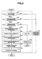
- FIG. 2 is a flowchart showing the operation of the first embodiment;
- FIG. 3 is a view similar to FIG. 1, showing a second embodiment of the present invention;
- FIG. 4 is a view similar to FIG. 2, showing the operation of the second embodiment;
- FIG. 5 is a view similar to FIG. 3, showing a third embodiment of the present invention; and
- FIG. 6 is a view similar to FIG. 4, showing the operation of the third embodiment.
-
- Referring to the drawings wherein like reference numerals designate like parts throughout the views, a description will be made with regard to a fail-safe processing system and method for internal combustion engines embodying the present invention.
- FIGS. 1-2 show a first embodiment of the present invention. Referring to FIG. 1, the fail-safe processing system comprises a
piston 1, a cylinder 2, anintake pipe 3, anexhaust pipe 5, anexhaust valve 6, an electronic-controlled throttle valve or electronic-controlledintake device 7, an intake-side variable valve-lift mechanism 8, an exhaust-side variable valve-lift mechanism 9, an electronic control unit (ECU) 10, anaccelerator opening sensor 11, an engine-speed sensor 12, and abrake sensor 13. -
ECU 10 comprises a throttle-valve opening control part or means 10a, a first failure-diagnosis part or means 10b, a failure-mode determination part or means 10c, a target intake-air amount calculation part or means 10d, a target intake-air amount restriction part or means 10e, a target valve-lift calculation part or means 10f, a valve-lift control part or means 10g, a brake-action determination part or means 10h, and a fuel-cut part or means 10i. Target intake-airamount calculation part 10d, target intake-airamount restriction part 10e, target valve-lift calculation part 10f, and valve-lift control part 10g serve to carry out tail-safe processing as defined, e.g. inclaim 1. Fuel-cutpart 10i serves to carry out fail-safe processing as defined, e.g. inclaim 3. - Accelerator-
opening sensor 11 senses an accelerator opening and an accelerator-opening variation, engine-speed sensor 12 senses an engine speed, andbrake sensor 13 senses a brake action. - Electronic-controlled
throttle valve 7 is subjected to opening control by throttle-valveopening control part 10a ofECU 10 and in accordance with an accelerator-opening signal or the like sensed by accelerator-opening sensor 11 so as to control an intake-air amount. - Intake-side variable valve-
lift mechanism 8 inherently carries out variable control of a lift amount of intake valve 4 to enhance the combustion and output performance of the engine. During control at fail-safe time as will be described later,mechanism 8 also carries out control of an intake-air amount to be supplied to cylinder 2. - Likewise, exhaust-side variable valve-
lift mechanism 9 inherently carries out variable control of a lift amount ofexhaust valve 6 to enhance the combustion and output performance of the engine. During control at fail-safe time as will be described later,mechanism 9 also carries out control of an exhaust-air amount to be discharged from cylinder 2. - Referring to FIG. 2, the operation of the first embodiment will be described. At a
step 201, a first failure diagnosis is carried out by first failure-diagnosis part 10b, i.e. it is determined whether or not a failure of electronic-controlledthrottle valve 7 occurs, i.e.throttle valve 7 fails to operate in accordance with a command of throttle-valveopening control part 10a. If it is determined that no failure of electronic-controlledthrottle valve 7 occurs, control proceeds to astep 210 where ordinary valve-lift control is carried out, and then control comes to an end. - On the other hand, at
step 201, if it is determined that a failure of electronic-controlledthrottle valve 7 occurs, control proceeds to astep 202 where failure-mode determination is carried out by failure-mode determination part 10c, i.e. it is determined whether or not a mode of failure of electronic-controlledthrottle valve 7 is vehicle accelerating mode. If it is determined that the failure mode is not vehicle accelerating mode, control proceeds to astep 210 where ordinary valve-lift control is carried out, and then control comes to an end. - On the other hand, at
step 202, if it is determined that the failure mode is vehicle accelerating mode, control proceeds to astep 203 where brake-action determination is carried out by brake-action determination part 10h, i.e. it is determined whether or not vehicle deceleration can be made by brake operation. Specifically, it is determined whether or not the negative pressure can be produced as brake-force source. If it is determined that vehicle deceleration can be made by brake operation, control proceeds to steps 204-209 wherein fail-safe processing is carried out - Specifically, at
step 204, an accelerator opening and accelerator-opening variation detected by accelerator-opening sensor 11 are read in memory, whereas atstep 205, an engine speed detected by engine-speed sensor 12 is read in memory. - At
subsequent step 206, a target intake-air amount is calculated by target intake-airamount calculation part 10d in accordance with the detected engine speed and the detected accelerator opening and accelerator-opening variation and in response to driver's requirements for vehicle acceleration or deceleration. - At
subsequent step 207, the calculated target intake-air amount is restricted by target intake-airamount restriction part 10e to have less engine output than a target value thereof. - At
subsequent step 208, a target valve-lift amount is calculated by target valve-lift calculation part 10f in accordance with the restricted target intake-air amount and the engine speed. - Finally, at
step 209, intake-side variable valve-lift mechanism 8 and exhaust-side variable valve-lift mechanism 9 are controlled by valve-lift control part 10g to achieve the calculated target valve-lift amount Then, control comes to an end, and returns to the start. - On the other hand, at
step 203, if it is determined that vehicle deceleration cannot be made by brake operation, control proceeds to astep 211 where fuel cut is carried out, and then control proceeds to astep 212 where the engine is stopped. Fuel cut may be carried out after a predetermined period of time of fuel supply. - Next, the effect of the first embodiment will be described. In the first embodiment, when first failure-
diagnosis part 10b reveals that a failure of electronic-controlledthrottle valve 7 occurs, and failure-mode determination part 10c reveals that the failure mode is vehicle accelerating mode, lift amounts of intake valve 4 andexhaust valve 6 for variable valve-lift mechanisms
This allows driver's recognition of occurrence of a failure of electronic-controlledthrottle valve 7, avoiding of vehicle acceleration or deceleration contrary to his intention, and continuous vehicle running for evacuation to safety. - Moreover, the lift amounts of intake and
exhaust valves 4, 6 are controlled through fail-safe processing to gradually reduce an intake-air amount to be supplied to cylinder 2 and an exhaust-air amount to be discharged therefrom, enabling driver's recognition of occurrence of a failure of electronic-controlledthrottle valve 7 in avoiding insecure conditions due to abrupt reduction in engine output torque. - As described above, in the event of failure of electronic-controlled
throttle valve 7, the lift amounts of intake andexhaust valves 4, 6 for variable valve-lift mechanisms throttle valve 7, so that in the event of failure withthrottle valve 7 in full open, the negative pressure cannot be produced, leading to possible reduction in brake force. On the other hand, in the first embodiment, if a failure of electronic-controlledthrottle valve 7 occurs with the vehicle being ready for acceleration, and a brake force reduces, fuel cut is carried out to stop the vehicle. This allows emergency stop of the vehicle even with reduced brake force, avoiding insecure conditions. It is noted that even when a negative-pressure source of the brake is produced by a negative-pressure pump, the above control can deal with all situations of the vehicle with reduced brake force. - FIGS. 3-4 show a second embodiment of the present invention which is substantially the same as the first embodiment except that fail-safe processing is carried out in the event of failure of variable valve-
lift mechanism - Referring to FIG. 3, the fail-safe processing system comprises a throttle-
opening sensor 14, an intake-air amount sensor 15, and a valve-lift sensor 16. Throttle-opening sensor 14 senses a throttle opening, intake-air amount sensor 15 senses an intake-air amount, and valve-lift sensor 16 senses a valve-lift amount. -
ECU 10 comprises a throttle-opening control part or means 10a, a second failure-diagnosis part or means 10j, a normality determination part or means 10k for valve-lift sensor 16 in variable valve-lift mechanism, a first target throttle-opening calculation part or means 10m, a valve-lift amount estimation part or means 10n, and a second target throttle-opening calculation part or means 10p. Throttle-opening control part 10a and first target throttle-opening calculation part 10m serve to carry out fail-safe processing as defined, e.g. inclaim 5. Throttle-openingcontrol part 10a, valve-liftamount estimation part 10n, and second target throttle-opening calculation part 10p serve to carry out fail-safe processing as defined, e.g. inclaim 7. - Referring to FIG. 4, the operation of the second embodiment will be described. At a
step 301, a second failure diagnosis is carried out by second failure-diagnosis part 10j, i.e. it is determined whether or not variable valve-lift mechanism lift mechanism step 307 where ordinary throttle-opening control is carried out, and then control comes to an end. - On the other hand, at
step 301, if it is determined that variable valve-lift mechanism step 302 where normality determination for valve-lift sensor 16 in variable valve-lift mechanism is carried out bynormality determination part 10k, i.e. it is determined whether or not valve-lift sensor 16 is in working order. If it is determined that valve-lift sensor 16 is in working order, control proceeds to steps 303-314 where fail-safe processing is carried out. - Specifically, at
step 303, an accelerator opening and accelerator-opening variation detected by accelerator-openingsensor 11 are read in memory. Atstep 304, a valve-lift amount detected by valve-lift sensor 16 is read in memory. And atstep 305, an engine speed detected by engine-speed sensor 12 is read in memory. - At
subsequent step 306, a first target throttle opening is calculated by first target throttle-opening calculation part 10m in accordance with the detected accelerator opening, etc. The calculated first target throttle opening is corrected by the detected valve-lift amount, engine speed, etc. to obtain a final value of first target throttle opening at the time of failure. The final value of first target throttle opening is determined to allow a gradual reduction in intake-air amount while maintaining the vehicle in the runnable state. - Finally, at
step 314, opening control is carried out by throttle-openingcontrol part 10a such that electronic-controlledthrottle valve 7 has final value of first target throttle opening. Then, control comes to an end. - On the other hand, at
step 302, if it is determined that valve-lift sensor 16 is not in working order, control proceeds to steps 308-314 where fail-safe processing is carried out Specifically, atstep 308, an accelerator opening and accelerator-opening variation detected by accelerator-openingsensor 11 are read in memory. Atstep 309, a throttle opening detected by throttle-openingsensor 14 is read in memory. Atstep 310, an engine speed detected by engine-speed sensor 12 is read in memory. Atstep 311, an intake-air amount detected by intake-air amount sensor 15 is read in memory. - Subsequently, at
step 312, a current valve-lift amount is estimated by first target throttle-opening calculation part 10n in accordance with the detected throttle opening, engine speed, and intake-air amount. Atstep 313, in a similar manner to atstep 306, a second target throttle opening is calculated by second target throttle-opening calculation part 10p in accordance with the detected accelerator opening, etc. and the estimated valve-lift amount. The calculated second target throttle opening is corrected by the estimated valve-lift amount, the detected engine speed, etc. to obtain a final value of second target throttle opening at the time of failure. The final value of second target throttle opening is determined to allow a gradual reduction in intake-air amount while maintaining the vehicle in the runnable state. In the event of failure with minimum valve-lift amount, the intake-air amount can be increased to maintain the vehicle in the runnable state. - Finally, at
step 314, opening control is carried out by throttle-openingcontrol part 10a such that electronic-controlledthrottle valve 7 has final value of second target throttle opening. Then, control comes to an end. - Next, the effect of the second embodiment will be described. In the second embodiment, when second failure-
diagnosis part 10j reveals that variable valve-lift mechanism normality determination part 10k reveals that valve-lift sensor 16 is in working order, the opening of electronic-controlledthrottle valve 7 is controlled through fail-safe processing (steps 303-306 and 314) to correspond to a target throttle opening obtained from the accelerator opening, valve-lift amount, and engine speed. This leads to achievement of optimal engine output torque at the time of failure without stopping the engine.
This allows driver's recognition of occurrence of a failure of variable valve-lift mechanism - Moreover, when second failure-
diagnosis part 10j reveals that variable valve-lift mechanism normality determination part 10k reveals that valve-lift sensor 16 is not in working order, the opening of electronic-controlledthrottle valve 7 is controlled through fail-safe processing (steps 308-314) to correspond to a target throttle opening obtained from the accelerator opening, valve-lift amount, and engine speed. This leads to achievement of optimal engine output torque at the time of failure without stopping the engine.
Thus, in the event of failure of valve-lift sensor 16, also, this allows driver's recognition of occurrence of a failure of variable valve-lift mechanism - Moreover, in opening control of electronic-controlled
throttle valve 7 carried out by throttle-openingcontrol part 10a, a target throttle opening at the time of failure is determined to allow a gradual reduction in intake-air amount while maintaining the vehicle in the runnable state. This allows driver's recognition of occurrence of a failure of variable valve-lift mechanism 8, 9 (and valve-lift sensor 16) in avoiding insecure conditions due to abrupt reduction in engine output torque. - FIGS. 5-6 show a third embodiment of the present invention which is substantially the same as the above embodiments except that fail-safe processing is carried out in the event of failure of one of electronic-controlled
throttle valve 7 and variable valve-lift mechanism - Referring to FIG. 5, in the third embodiment, the fail-safe processing system comprises, in addition to all structural elements in the first and second embodiments, a fuel-injection-amount adjustment part or means 10q and an ignition-timing adjustment part or means 10r. Fuel-injection-amount adjustment part 10q serves to carry out fail-safe processing as defined, e.g. in
claim 9. - Referring to FIG. 6, the operation of the third embodiment will be described. At a
step 401, it is determined in first failure-diagnosis part 10b whether or not a failure of electronic-controlledthrottle valve 7 occurs, i.e.throttle valve 7 fails to operate in accordance with a command of throttle-valveopening control part 10a. If it is determined that a failure of electronic-controlledthrottle valve 7 occurs, control proceeds to a step 402. - At step 402, it is determined in second failure-
diagnosis part 10j whether or not variable valve-lift mechanism lift mechanism step 403 where driver's requirements in the form of an accelerator-opening signal derived from accelerator-openingsensor 11, a brake-operation signal derived frombrake sensor 13, etc. are read in memory, then control proceeds to a step 404. - At step 404, it is determined based on the accelerator-opening signal, the brake-operation signal, etc. whether or not driver's running requirements exist. If it is determined that running requirements exist, control proceeds to a
step 405 where it is determined whether or not the vehicle is in the runnable state. If it is determined that the vehicle is in the runnable state, control proceeds to astep 406 where a fuel-injection amount is adjusted by fuel-injection-amount adjustment part 10q. - At a
subsequent step 407, an ignition timing is adjusted by ignition-timing adjustment part 10r, and then control comes to an end. It is noted that adjustment of the fuel-injection amount and that of the ignition timing are so carried out as to decrease engine output when the intake-air amount is greater, and increase engine output when the amount is smaller. - If it is determined at step 404 that running requirements do not exist, or it is determined at
step 405 that the vehicle is not in the runnable state, control proceeds to astep 408 where fuel cut is carried out by fuel-cut part 10i, and then control proceeds to astep 409 where the engine is stopped. Fuel-cut part 10i serves to carry out second and third fail-safe processings as defined, e.g. inclaims - At
step 401, if it is determined that a failure of electronic-controlledthrottle valve 7 does not occur, control proceeds to astep 410 where it is determined in second failure-diagnosis part 10j whether or not variable valve-lift mechanism lift mechanism step 411 where processing at the time of failure of variable valve-lift mechanism - At
step 410, if it is determined that that variable valve-lift mechanism step 412 where ordinary valve-lift control and ordinary throttle-opening control are carried out, and then control comes to an end. - At step 402, if it is determined that variable valve-
lift mechanism step 413 where control at steps 202-212 in FIG. 2 is carried out, and then control comes to an end. - As described above, the third embodiment provides, in addition to the same effect as in the first and second embodiments, a further effect that even in the event of failure of one of electronic-controlled
throttle valve 7 and variable valve-lift mechanism - Moreover, in the event of failure of both of electronic-controlled
throttle valve 7 and variable valve-lift mechanism
On the other hand, when running requirements do not exist, and the vehicle is not in the runnable state, fuel cut is carried out, which is followed by engine stop processing. This allows avoiding of vehicle acceleration contrary to driver's intention. - Having described the present invention with regard to the preferred embodiments, it is to be understood that the present invention is not limited thereto, and various changes and modifications can be made without departing from the scope of the present invention.
- By way of example, in the first and third embodiments, fail-safe processing is carried out by controlling both intake-side and exhaust-side variable valve-
lift mechanisms lift mechanism 8 only. - Moreover, in the second and third embodiments, a final value of target throttle opening at the time of failure is determined to allow prevention of unstable vehicle behavior caused by a failure of variable valve-
lift mechanisms lift mechanisms
Furthermore, variable valve-lift mechanisms - The entire contents of Japanese Patent Application 2001-274154 filed September 10, 2001 and Japanese Patent Application 2000-315534 filed October 16, 2000 are incorporated hereby by reference.
Claims (18)
- A fail-safe processing method for an internal combustion engine, the engine including at least an electronic-controlled intake device and a variable valve-lift mechanism for controlling a valve-lift amount, the method comprising:carrying out a failure diagnosis for determining whether a failure of the electronic-controlled intake device occurs;determining whether a mode of the failure of the electronic-controlled intake device is a vehicle accelerating mode when it is determined that the failure occurs;carrying out a fail-safe processing when it is determined that the failure mode is the vehicle accelerating mode, wherein the fail-safe processing determines an optimal value of the valve-lift amount; andcontrolling the variable valve-lift mechanism in accordance with the optimal value of the valve-lift amount
- The fail-safe processing method as claimed in claim 1, wherein the optimal value of the valve-lift amount is determined to allow a gradual reduction in an intake-air amount to be supplied to a cylinder.
- The fail-safe processing method as claimed in claim 1, further comprising:determining whether a vehicle deceleration can be made by brake operation; andcarrying out another fail-safe processing when it is determined that the vehicle deceleration cannot be made, wherein the another fail-safe processing carries out fuel cut
- The fail-safe processing method as claimed in claim 3, wherein fuel cut is carried out after a predetermined period of time of fuel supply.
- A fail-safe processing method for an internal combustion engine, the engine including at least an electronic-controlled intake device and a variable valve-lift mechanism for controlling a valve-lift amount, the method comprising:carrying out a failure diagnosis for determining whether a failure of the variable valve-lift mechanism occurs;carrying out a fail-safe processing when it is determined that the failure of the variable valve-lift mechanism occurs, wherein the fail-safe processing determines an optimal value of an intake-air amount to be supplied to a cylinder; andcontrolling the electronic-controlled intake device in accordance with the optimal value of the intake-air amount
- The fail-safe processing method as claimed in claim 5, wherein the optimal value of the valve-lift amount is determined to allow a gradual reduction in an intake-air amount to be supplied to a cylinder.
- The fail-safe processing method as claimed in claim 5, further comprising:determining whether a sensor for sensing the valve-lift amount is in working order;estimating the valve-lift amount for the variable valve-lift mechanism; andcarrying out another fail-safe processing when it is determined that the failure of the variable valve-lift mechanism occurs and that the sensor fails to be in working order, wherein the another fail-safe processing determines the optimal value of the intake-air amount to be supplied to the cylinder in accordance with the estimated valve-lift amount.
- A fail-safe processing method for an internal combustion engine, the engine including at least an electronic-controlled intake device and a variable valve-lift mechanism for controlling a valve-lift amount, the method comprising:carrying out a first failure diagnosis for determining whether a failure of the electronic-controlled intake device occurs;determining whether a mode of the failure of the electronic-controlled intake device is a vehicle accelerating mode when it is determined that the failure occurs;carrying out a first fail-safe processing when it is determined that the failure mode is the vehicle accelerating mode, wherein the first fail-safe processing determines an optimal value of the valve lift amount;controlling the variable valve-lift mechanism in accordance with the optimal value of the valve lift amount;carrying out a second failure diagnosis for determining whether a failure of the variable valve-lift mechanism occurs;carrying out a second fail-safe processing when it is determined that the failure of the variable valve-lift mechanism occurs, wherein the second fail-safe processing determines an optimal value of an intake-air amount to be supplied to a cylinder; andcontrolling the electronic-controlled intake device in accordance with the optimal value of the intake-air amount.
- The fail-safe processing method as claimed in claim 8, further comprising:carrying out a third fail-safe processing when it is determined that the failure of the electronic-controlled intake device occurs, that the failure mode is the vehicle accelerating mode, and that the failure of the variable valve-lift mechanism occurs, wherein the third fail-safe processing adjusts a fuel-injection amount
- A fail-safe processing system for an internal combustion engine, comprising:an electronic-controlled intake device;a variable valve-lift mechanism that controls a valve-lift amount; andan electronic control unit (ECU) electrically connected to the electronic-controlled intake device and the variable valve-lift mechanism, wherein the ECU is constructed to:carry out a failure diagnosis for determining whether a failure of the electronic-controlled intake device occurs;determine whether a mode of the failure of the electronic-controlled intake device is a vehicle accelerating mode when it is determined that the failure occurs;carry out a fail-safe processing when it is determined that the failure mode is the vehicle accelerating mode, wherein the fail-safe processing determines an optimal value of the valve-lift amount; andcontrol the variable valve-lift mechanism in accordance with the optimal value of the valve-lift amount
- The fail-safe processing system as claimed in claim 10, wherein the optimal value of the valve-lift amount is determined to allow a gradual reduction in an intake-air amount to be supplied to a cylinder.
- The fail-safe processing system as claimed in claim 10, wherein the ECU is constructed to further:determine whether a vehicle deceleration can be made by brake operation; andcarry out another fail-safe processing when it is determined that the vehicle deceleration cannot be made, wherein the another fail-safe processing carries out fuel cut
- The fail-safe processing system as claimed in claim 12, wherein fuel cut is carried out after a predetermined period of time of fuel supply,
- A fail-safe processing system for an internal combustion engine, comprising:an electronic-controlled intake device;a variable valve-lift mechanism that controls a valve-lift amount; andan electronic control unit (ECU) electrically connected to the electronic-controlled intake device and the variable valve-lift mechanism, wherein the ECU is constructed to:carry out a failure diagnosis for determining whether a failure of the variable valve-lift mechanism occurs;carry out a fail-safe processing when it is determined that the failure of the variable valve-lift mechanism occurs, wherein the fail-safe processing determines an optimal value of an intake-air amount to be supplied to a cylinder; andcontrol the electronic-controlled intake device in accordance with the optimal value of the intake-air amount
- The fail-safe processing system as claimed in claim 14, wherein the optimal value of the valve-lift amount is determined to allow a gradual reduction in an intake-air amount to be supplied to a cylinder.
- The fail-safe processing system as claimed in claim 14, wherein the ECU is constructed to further:determine whether a sensor for sensing the valve-lift amount is in working order;estimate the valve-lift amount for the variable valve-lift mechanism; andcarry out another fail-safe processing when it is determined that the failure of the variable valve-lift mechanism occurs and that the sensor fails to be in working order, wherein the another fail-safe processing determines the optimal value of the intake-air amount to be supplied to the cylinder in accordance with the estimated valve-lift amount
- A fail-safe processing system for an internal combustion engine, comprising:an electronic-controlled intake device;a variable valve-lift mechanism that controls a valve-lift amount; andan electronic control unit (ECU) electrically connected to the electronic-controlled intake device and the variable valve-lift mechanism, wherein the ECU is constructed to:carry out a first failure diagnosis for determining whether a failure of the electronic-controlled intake device occurs;determine whether a mode of the failure of the electronic-controlled intake device is a vehicle accelerating mode when it is determined that the failure occurs;carry out a first fail-safe processing when it is determined that the failure mode is the vehicle accelerating mode, wherein the first fail-safe processing determines an optimal value of the valve lift amount;control the variable valve-lift mechanism in accordance with the optimal value of the valve lift amount;carry out a second failure diagnosis for determining whether a failure of the variable valve-lift mechanism occurs;carry out a second fail-safe processing when it is determined that the failure of the variable valve-lift mechanism occurs, the second fail-safe processing determining an optimal value of an intake-air amount to be supplied to a cylinder; andcontrol the electronic-controlled intake device in accordance with the optimal value of the intake-air amount
- The fail-safe processing system, wherein the ECU is constructed to further:carry out a third fail-safe processing when it is determined that the failure of the electronic-controlled intake device occurs, that the failure mode is the vehicle accelerating mode, and that the failure of the variable valve-lift mechanism occurs, wherein the third fail-safe processing adjusts a fuel-injection amount
Applications Claiming Priority (4)
| Application Number | Priority Date | Filing Date | Title |
|---|---|---|---|
| JP2000315534 | 2000-10-16 | ||
| JP2000315534 | 2000-10-16 | ||
| JP2001274154 | 2001-09-10 | ||
| JP2001274154A JP4235376B2 (en) | 2000-10-16 | 2001-09-10 | Fail-safe treatment device for internal combustion engine |
Publications (3)
| Publication Number | Publication Date |
|---|---|
| EP1199456A2 true EP1199456A2 (en) | 2002-04-24 |
| EP1199456A3 EP1199456A3 (en) | 2003-06-04 |
| EP1199456B1 EP1199456B1 (en) | 2006-08-09 |
Family
ID=26602174
Family Applications (1)
| Application Number | Title | Priority Date | Filing Date |
|---|---|---|---|
| EP01124626A Expired - Lifetime EP1199456B1 (en) | 2000-10-16 | 2001-10-15 | Fail-safe processing system and method for internal combustion engine |
Country Status (4)
| Country | Link |
|---|---|
| US (1) | US6491022B2 (en) |
| EP (1) | EP1199456B1 (en) |
| JP (1) | JP4235376B2 (en) |
| DE (1) | DE60122084T2 (en) |
Cited By (3)
| Publication number | Priority date | Publication date | Assignee | Title |
|---|---|---|---|---|
| EP1375883A2 (en) * | 2002-06-18 | 2004-01-02 | Robert Bosch Gmbh | Method for operating an internal combustion engine, method for checking such a method for operating an internal combustion engine, internal combustion engine and control unit |
| EP2103800A3 (en) * | 2007-07-10 | 2013-01-23 | Yamaha Hatsudoki Kabushiki Kaisha | Intake system and motorcycle including the same |
| DE102004014977B4 (en) | 2003-03-27 | 2018-10-31 | Toyota Jidosha Kabushiki Kaisha | An intake air quantity control apparatus and method for an internal combustion engine |
Families Citing this family (27)
| Publication number | Priority date | Publication date | Assignee | Title |
|---|---|---|---|---|
| JP2002322934A (en) * | 2001-04-26 | 2002-11-08 | Toyota Motor Corp | Intake air control device for internal combustion engine |
| JP4049557B2 (en) * | 2001-07-26 | 2008-02-20 | 株式会社日立製作所 | Fail-safe control device for internal combustion engine |
| JP4409800B2 (en) * | 2001-11-28 | 2010-02-03 | 三菱電機株式会社 | Engine control device |
| JP3706335B2 (en) * | 2001-12-12 | 2005-10-12 | 本田技研工業株式会社 | Internal combustion engine failure determination device |
| JP2005016340A (en) * | 2003-06-24 | 2005-01-20 | Hitachi Unisia Automotive Ltd | Fail safe controller for internal combustion engine with variable valve sytem |
| JP4137731B2 (en) * | 2003-07-28 | 2008-08-20 | 本田技研工業株式会社 | Valve control device for internal combustion engine |
| JP4083647B2 (en) * | 2003-08-21 | 2008-04-30 | トヨタ自動車株式会社 | Intake air amount control device for internal combustion engine |
| JP4266170B2 (en) * | 2004-02-02 | 2009-05-20 | 株式会社日立製作所 | Air quantity control device for internal combustion engine |
| US7066121B2 (en) * | 2004-03-19 | 2006-06-27 | Ford Global Technologies, Llc | Cylinder and valve mode control for an engine with valves that may be deactivated |
| US7082934B2 (en) * | 2004-08-24 | 2006-08-01 | Ford Global Technologies, Llc | Controlling spark for an engine with controllable valves |
| JP4767069B2 (en) * | 2005-05-02 | 2011-09-07 | ヤマハ発動機株式会社 | Engine control device for saddle riding type vehicle and engine control method therefor |
| US7600495B2 (en) * | 2005-08-23 | 2009-10-13 | Ford Global Technologies, Llc | Method for controlling an engine having variable cam timing |
| JP4098803B2 (en) * | 2005-11-18 | 2008-06-11 | 三菱電機株式会社 | In-vehicle drive control device |
| JP4536649B2 (en) * | 2005-12-14 | 2010-09-01 | 本田技研工業株式会社 | Variable valve gear |
| EP1995436B1 (en) * | 2007-05-25 | 2010-07-07 | Magneti Marelli S.p.A. | Control method for a motorized vehicle in the case of a fault that advices/imposes driving the vehicle with reduced performance |
| JP4321647B2 (en) * | 2007-09-21 | 2009-08-26 | トヨタ自動車株式会社 | Internal combustion engine abnormal output limit device |
| US8428809B2 (en) * | 2008-02-11 | 2013-04-23 | GM Global Technology Operations LLC | Multi-step valve lift failure mode detection |
| JP5573227B2 (en) * | 2010-03-01 | 2014-08-20 | 株式会社デンソー | Starter control device |
| US8942908B2 (en) * | 2010-04-30 | 2015-01-27 | GM Global Technology Operations LLC | Primary torque actuator control systems and methods |
| JP5541132B2 (en) * | 2010-12-10 | 2014-07-09 | 株式会社デンソー | Vehicle control device |
| JP5565353B2 (en) * | 2011-03-23 | 2014-08-06 | 株式会社デンソー | Engine control device |
| US9512749B2 (en) * | 2012-06-05 | 2016-12-06 | GM Global Technology Operations LLC | System and method for calibrating a valve lift sensor and evaluating a valve lift sensor and a hydraulic valve actuator |
| JP5682736B2 (en) * | 2012-10-25 | 2015-03-11 | トヨタ自動車株式会社 | Internal combustion engine and control device for internal combustion engine |
| JP6450587B2 (en) * | 2014-12-25 | 2019-01-09 | ダイハツ工業株式会社 | Control device for internal combustion engine |
| JP6623749B2 (en) * | 2015-12-25 | 2019-12-25 | 三菱自動車工業株式会社 | Engine control device |
| KR20200067488A (en) * | 2018-12-04 | 2020-06-12 | 현대자동차주식회사 | Method for Control To Response CVVD Malfunction and Continuous Variable Valve Duration System Thereof |
| KR20210047132A (en) * | 2019-10-21 | 2021-04-29 | 현대자동차주식회사 | Method for Control To Establish CVVD Start Up and Continuous Variable Valve Duration System Thereof |
Citations (2)
| Publication number | Priority date | Publication date | Assignee | Title |
|---|---|---|---|---|
| JP2000315534A (en) | 1999-03-26 | 2000-11-14 | Amphenol Tuchel Electronics Gmbh | Smart card connector |
| JP2001274154A (en) | 2000-01-18 | 2001-10-05 | Applied Materials Inc | Film formation method, apparatus, and semiconductor device and method of manufacturing the same |
Family Cites Families (9)
| Publication number | Priority date | Publication date | Assignee | Title |
|---|---|---|---|---|
| US5233530A (en) * | 1988-11-28 | 1993-08-03 | Mitsubishi Jidosha Kogyo Kabushiki Kaisha | Engine controlling system which reduces the engine output upon detection of an abnormal condition |
| JP2841960B2 (en) * | 1991-09-17 | 1998-12-24 | 日産自動車株式会社 | Engine output control device |
| JP3309658B2 (en) * | 1995-08-25 | 2002-07-29 | トヨタ自動車株式会社 | Abnormality detection device for valve timing control device of internal combustion engine |
| US6276331B1 (en) | 1998-08-05 | 2001-08-21 | Unisia Jecs Corporation | Method and apparatus for fail-safe controlling internal combustion engine with electronic controlled throttle system |
| JP4118403B2 (en) * | 1998-08-05 | 2008-07-16 | 株式会社日立製作所 | Fail-safe control device for electric throttle type internal combustion engine |
| US6209518B1 (en) | 1998-08-05 | 2001-04-03 | Unisia Jecs Corporation | Method and apparatus for fail safe control of an electronically controlled throttle valve of an internal combustion engine |
| JP3694406B2 (en) | 1998-08-28 | 2005-09-14 | 株式会社日立製作所 | Fail-safe control device for electric throttle type internal combustion engine |
| JP3932712B2 (en) * | 1999-01-12 | 2007-06-20 | 日産自動車株式会社 | Engine intake control device |
| JP2000356143A (en) * | 1999-06-14 | 2000-12-26 | Toyota Motor Corp | Combustion control device for internal combustion engine |
-
2001
- 2001-09-10 JP JP2001274154A patent/JP4235376B2/en not_active Expired - Fee Related
- 2001-10-15 EP EP01124626A patent/EP1199456B1/en not_active Expired - Lifetime
- 2001-10-15 DE DE60122084T patent/DE60122084T2/en not_active Expired - Lifetime
- 2001-10-16 US US09/977,256 patent/US6491022B2/en not_active Expired - Lifetime
Patent Citations (2)
| Publication number | Priority date | Publication date | Assignee | Title |
|---|---|---|---|---|
| JP2000315534A (en) | 1999-03-26 | 2000-11-14 | Amphenol Tuchel Electronics Gmbh | Smart card connector |
| JP2001274154A (en) | 2000-01-18 | 2001-10-05 | Applied Materials Inc | Film formation method, apparatus, and semiconductor device and method of manufacturing the same |
Cited By (4)
| Publication number | Priority date | Publication date | Assignee | Title |
|---|---|---|---|---|
| EP1375883A2 (en) * | 2002-06-18 | 2004-01-02 | Robert Bosch Gmbh | Method for operating an internal combustion engine, method for checking such a method for operating an internal combustion engine, internal combustion engine and control unit |
| EP1375883A3 (en) * | 2002-06-18 | 2005-12-07 | Robert Bosch Gmbh | Method for operating an internal combustion engine, method for checking such a method for operating an internal combustion engine, internal combustion engine and control unit |
| DE102004014977B4 (en) | 2003-03-27 | 2018-10-31 | Toyota Jidosha Kabushiki Kaisha | An intake air quantity control apparatus and method for an internal combustion engine |
| EP2103800A3 (en) * | 2007-07-10 | 2013-01-23 | Yamaha Hatsudoki Kabushiki Kaisha | Intake system and motorcycle including the same |
Also Published As
| Publication number | Publication date |
|---|---|
| JP4235376B2 (en) | 2009-03-11 |
| US20020066435A1 (en) | 2002-06-06 |
| JP2002195083A (en) | 2002-07-10 |
| DE60122084T2 (en) | 2006-11-30 |
| EP1199456B1 (en) | 2006-08-09 |
| EP1199456A3 (en) | 2003-06-04 |
| DE60122084D1 (en) | 2006-09-21 |
| US6491022B2 (en) | 2002-12-10 |
Similar Documents
| Publication | Publication Date | Title |
|---|---|---|
| US6491022B2 (en) | Fail-safe processing system and method for internal combustion engine | |
| JP3317841B2 (en) | Ignition timing control device for internal combustion engine | |
| US6178371B1 (en) | Vehicle speed control system and method | |
| US5623906A (en) | Fixed throttle torque demand strategy | |
| EP3406880B1 (en) | Waste gate valve control method and control device | |
| JP6441199B2 (en) | Control device for internal combustion engine | |
| EP1450025B1 (en) | Negative pressure control apparatus and method therefore in an internal combustion engine | |
| JP2518319B2 (en) | Fail-safe device for internal combustion engine for vehicles | |
| JP2000248966A (en) | Operating method of internal combustion engine with combustion chamber receiving direct fuel injection and control device thereof | |
| JP3914122B2 (en) | Ignition timing control device for internal combustion engine | |
| JP3041089B2 (en) | Internal combustion engine deceleration control method | |
| JP4565863B2 (en) | Negative pressure control method for pneumatic booster | |
| JP3450765B2 (en) | Air conditioner cut control method | |
| JP3709749B2 (en) | Automatic engine starter for AT cars | |
| JP3291680B2 (en) | Vehicle engine control device | |
| JP3102227B2 (en) | Cylinder operation control method for multi-cylinder engine | |
| JP2560501B2 (en) | Supercharging pressure controller for vehicle exhaust turbocharged engine | |
| JP4309226B2 (en) | Control device for internal combustion engine | |
| KR20110060983A (en) | Engine pressure increase controlling method to improve brake performance and engine controlling device | |
| WO2024023960A1 (en) | Internal combustion engine control device | |
| JPH0612234Y2 (en) | Electronic control unit for diesel engine | |
| JP2518328B2 (en) | Fail-safe device for internal combustion engine for vehicles | |
| JP3714390B2 (en) | Internal combustion engine with a supercharger | |
| JPH0310015B2 (en) | ||
| JP3908006B2 (en) | Control method for internal combustion engine |
Legal Events
| Date | Code | Title | Description |
|---|---|---|---|
| PUAI | Public reference made under article 153(3) epc to a published international application that has entered the european phase |
Free format text: ORIGINAL CODE: 0009012 |
|
| 17P | Request for examination filed |
Effective date: 20011015 |
|
| AK | Designated contracting states |
Kind code of ref document: A2 Designated state(s): AT BE CH CY DE DK ES FI FR GB GR IE IT LI LU MC NL PT SE TR |
|
| AX | Request for extension of the european patent |
Free format text: AL;LT;LV;MK;RO;SI |
|
| PUAL | Search report despatched |
Free format text: ORIGINAL CODE: 0009013 |
|
| AK | Designated contracting states |
Designated state(s): AT BE CH CY DE DK ES FI FR GB GR IE IT LI LU MC NL PT SE TR |
|
| AX | Request for extension of the european patent |
Extension state: AL LT LV MK RO SI |
|
| 17Q | First examination report despatched |
Effective date: 20031107 |
|
| AKX | Designation fees paid |
Designated state(s): DE FR |
|
| RAP1 | Party data changed (applicant data changed or rights of an application transferred) |
Owner name: HITACHI, LTD. |
|
| GRAP | Despatch of communication of intention to grant a patent |
Free format text: ORIGINAL CODE: EPIDOSNIGR1 |
|
| GRAS | Grant fee paid |
Free format text: ORIGINAL CODE: EPIDOSNIGR3 |
|
| GRAA | (expected) grant |
Free format text: ORIGINAL CODE: 0009210 |
|
| AK | Designated contracting states |
Kind code of ref document: B1 Designated state(s): DE FR |
|
| REF | Corresponds to: |
Ref document number: 60122084 Country of ref document: DE Date of ref document: 20060921 Kind code of ref document: P |
|
| ET | Fr: translation filed | ||
| PLBE | No opposition filed within time limit |
Free format text: ORIGINAL CODE: 0009261 |
|
| STAA | Information on the status of an ep patent application or granted ep patent |
Free format text: STATUS: NO OPPOSITION FILED WITHIN TIME LIMIT |
|
| 26N | No opposition filed |
Effective date: 20070510 |
|
| PGFP | Annual fee paid to national office [announced via postgrant information from national office to epo] |
Ref country code: FR Payment date: 20081014 Year of fee payment: 8 |
|
| PGFP | Annual fee paid to national office [announced via postgrant information from national office to epo] |
Ref country code: DE Payment date: 20091008 Year of fee payment: 9 |
|
| REG | Reference to a national code |
Ref country code: FR Ref legal event code: ST Effective date: 20100630 |
|
| PG25 | Lapsed in a contracting state [announced via postgrant information from national office to epo] |
Ref country code: FR Free format text: LAPSE BECAUSE OF NON-PAYMENT OF DUE FEES Effective date: 20091102 |
|
| REG | Reference to a national code |
Ref country code: DE Ref legal event code: R119 Ref document number: 60122084 Country of ref document: DE Effective date: 20110502 |
|
| PG25 | Lapsed in a contracting state [announced via postgrant information from national office to epo] |
Ref country code: DE Free format text: LAPSE BECAUSE OF NON-PAYMENT OF DUE FEES Effective date: 20110502 |