EP1195575A1 - Procedure and device to determine surface coordinates and their application and positioning procedure for a laser emitter-detector - Google Patents
Procedure and device to determine surface coordinates and their application and positioning procedure for a laser emitter-detector Download PDFInfo
- Publication number
- EP1195575A1 EP1195575A1 EP01402559A EP01402559A EP1195575A1 EP 1195575 A1 EP1195575 A1 EP 1195575A1 EP 01402559 A EP01402559 A EP 01402559A EP 01402559 A EP01402559 A EP 01402559A EP 1195575 A1 EP1195575 A1 EP 1195575A1
- Authority
- EP
- European Patent Office
- Prior art keywords
- receiver
- photosensitive
- laser
- point
- coordinate
- Prior art date
- Legal status (The legal status is an assumption and is not a legal conclusion. Google has not performed a legal analysis and makes no representation as to the accuracy of the status listed.)
- Withdrawn
Links
Images


Classifications
-
- G—PHYSICS
- G01—MEASURING; TESTING
- G01B—MEASURING LENGTH, THICKNESS OR SIMILAR LINEAR DIMENSIONS; MEASURING ANGLES; MEASURING AREAS; MEASURING IRREGULARITIES OF SURFACES OR CONTOURS
- G01B11/00—Measuring arrangements characterised by the use of optical techniques
- G01B11/002—Measuring arrangements characterised by the use of optical techniques for measuring two or more coordinates
- G01B11/005—Measuring arrangements characterised by the use of optical techniques for measuring two or more coordinates coordinate measuring machines
- G01B11/007—Measuring arrangements characterised by the use of optical techniques for measuring two or more coordinates coordinate measuring machines feeler heads therefor
Definitions
- the invention relates to a device and a method for determining at least one coordinate of at least one point on the surface of an object, as well as uses of these.
- the invention also relates to a method for positioning an assembly laser transmitter - receiver intended to determine at least one coordinate of at least minus a point on the surface of an object in three-dimensional space.
- the invention applies in particular to the dimensional metrological control of precision, but also to the mass production of objects whose dimensions must remain faithful to precise values and to the copying of shapes.
- micrometric or submicrometric measurement accuracy is required for certain items.
- the invention aims to overcome the drawbacks of the state of the art and to obtain precise, reliable and fast measurement of the coordinate of a point on the surface of an object.
- This device makes it possible to perform coordinate measurements in a manner precisely reproducible and repetitive, including a large number of objects on left surfaces, while reducing the time to do so.
- the displacement means are suitable, according to a characteristic of the invention, to adjust the position of the laser transmitter - receiver assembly photosensitive in three orthonormal directions and include a goniometer for adjusting the position of the object to be measured around two axes orthogonal to the frame.
- means are provided for adjust the angular position of the laser transmitter - receiver assembly photosensitive about an axis of rotation relative to the frame.
- the photosensitive receiver includes a diode photosensitive whose laser radiation receiving area has a sufficient area to be scanned by the reflected or passed laser beam the object to be measured and providing a difference in potential or electric current depending on the radiation received in the reception area.
- the laser transmitter-receiver assembly photosensitive is arranged so that the incidence of the laser beam on the point of the object's surface has a component parallel to the direction in which the coordinate should be determined and that the receiver photosensitive receives the laser beam reflected by the object.
- the laser transmitter-receiver assembly photosensitive is arranged so that the incidence of the laser beam on the point of the object's surface has a component orthogonal to the direction in which the coordinate of the object must be determined and that the photosensitive receiver receives the laser beam passed through the object.
- the calculation means include a processing unit capable of controlling continuously adjustment positions of the displacement means, to be collected continuously the quantity supplied by the receiver and to be calculated from these adjustment positions and quantities provided a point coordinate of the object surface for each setting.
- a memory is provided between the photosensitive receiver and processing unit for storing quantities supplied by the photosensitive receiver.
- the photosensitive receiver to determine its dimension curve corresponding to the quantity provided by it. This allows you to calculate the coordinate automatically.
- the position of the laser transmitter - photosensitive receiver assembly in three directions orthonormal as well as its angular position around an axis of rotation and one adjusts the angular position of the object to be measured around two axes orthogonal.
- the transmitter assembly is oriented laser - photosensitive receiver so that the incidence of the laser beam on the point on the surface of the object has a component parallel to the direction according to which the coordinate of the object must be determined and that the photosensitive receiver receives the laser beam reflected by the object.
- the transmitter assembly is oriented laser - photosensitive receiver so that the incidence of the laser beam on the point on the surface of the object has a component orthogonal to the direction in which the coordinate of the object must be determined and that the photosensitive receiver receives the laser beam passed through the object.
- the adjustment positions are continuously controlled, one with respect to the other of the laser transmitter-photosensitive receiver and of the object to be measure, the quantity supplied by the receiver is continuously collected and calculates from these adjustment positions and the quantities provided a coordinate of a point on the surface of the object for each adjustment.
- the quantities supplied by the photosensitive receiver before calculating the coordinate of the object are supplied by the photosensitive receiver before calculating the coordinate of the object.
- the invention also provides for the use of a measuring device or a above-mentioned measurement method for determining the surface-envelope of an object.
- Another application of the invention provides for the use of a measuring device or a measurement method mentioned above to machine a part from contact details provided beforehand by the device or process.
- Another application of the invention provides for the use of a measuring device or a measurement method mentioned above to make a mold of part with contact details provided beforehand by the device or process.
- a method of positioning of a laser transmitter-receiver assembly According to a third aspect of the invention, there is provided a method of positioning of a laser transmitter-receiver assembly.
- a laser beam behaves like a set of "fibers" luminous and, in the metrological applications previously described, only a limited number of these fibers are active, i.e. participate in the statement of the desired coordinates.
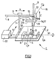
- the measuring device 1 comprises a horizontal table 2 or a support frame for a plate 3 provided to immobilize the object O to be measured.
- the plate 3 comprises a chassis 4 movable in rotation about a vertical axis Z1 relative to the table and an object holder 5 movable in rotation about an axis X1 horizontal with respect to chassis 4.
- a goniometer 6 makes it possible to adjust prescribed manner the angular positions of the holder 5 with respect to the table 2.
- the axes X1 and Z1 are concurrent.
- the table can have any other position, for example a vertical position.
- a vertical pillar 7 supporting is mounted movable in translation relative to the table 2 in a horizontal Y direction perpendicular to the X1 direction horizontal.
- a cross member 8 is mounted movable in translation in the direction of its length along a horizontal X direction parallel to direction X1.
- a gantry not shown can also be provided on table 2 instead of pillar 7 and cross member 8.
- a vertical arm 9 is mounted movable in the direction of its length on the crosspiece 8 in a vertical direction Z parallel to the direction Z1.
- Means of displacement 10, 11, 12 of the pillar 7, of the cross member 8 and of the arm 9 according to their respective degrees of freedom Y, X and Z with respect to table 2, pillar 7 and the cross 8 are provided on the latter.
- the means of movement 10, 11, 12 can be ordered to obtain prescribed coordinates in X, Y, Z of arm 9 relative to table 2.
- a measuring head 14 is mounted on the end part 15 of the arm 9, turned towards table 2.
- the head 14 is articulated in rotation about an axis of articulation 16 parallel to the direction Y.
- Adjustable means 16a for moving the angular position around the axis 16 of the head 14 relative to the part end 15 of arm 9 are provided.
- the measuring head is fixedly mounted on the arm, while the object holder is movable in rotation around three orthonormal axes.
- the three axes of translation and the three axes of rotation can also be provided in part or entirely on the head or on the object-holder.
- the axes with respect to which the translations are carried out and / or rotations are not orthonormal, while defining a system of coordinates in three-dimensional space, allowing any orientation directional of the head in it.
- the head 14 includes a laser emitter 17, for example in the form of a diode laser, and a photosensitive receiver 18, for example in the form of a diode photosensitive.
- the transmitter 17 and the receiver 18 are fixed one with respect to the other.
- the emitter 17 emits a laser beam focused in a fixed direction 19 relative to the head 14.
- the receiver 18 is able to transform the laser beam reflected by the object or passed by it and received in a representative quantity of a dimension.
- the receiver 18 comprises a photosensitive zone 20 of reception having a certain extent, transverse to the direction 19 of the ray laser and outward facing.
- a potential difference or a current electric is produced at the output of receiver 18 depending on the part of the reception zone 20, which is effectively reached by laser radiation.
- the characteristic of the receiver output quantity - coordinate of the part of zone 20, reached by laser radiation is determined during a calibration prior.
- the extent of the reception area 20 is sufficient to be scanned by the laser beam reflected or passed through the object O to be measured.
- the laser beam emitted by the transmitter 17 is directed in the direction incident 19 on the point P of the surface of the object O whose coordinate must be measured.
- the receiver 18 and the transmitter 17 are side by side on the head.
- the head is formed for example of a laser pointer.
- the head is oriented so that the reception area 18 receives the laser beam reflected by the object at point P, and that the laser beam is not directed along the normal to the surface of the object O at point P.
- the incidence of the laser beam on point P of the surface of the object has a component parallel to the direction in which the coordinate must be measured.
- a displacement of the object O relative to the next head 14 the direction 19 of the incident ray thus causes a displacement of the part illuminated by the ray reflected on the reception area 20, causing a change of the output variable of the receiver 18.
- the head 14 is arranged so that the reception area 20 receives the laser radiation passed through the object.
- the transmitter 17 and the receiver 18 are located on either side of the object O to be measured and of the object-holder 5, and are immobilized relative to each other by means of a bar of attachment to which they are attached and itself attached to the end portion 15 of the arm 9.
- the object O intercepts part of the layer 21 of laser radiation issued by transmitter 17 and lets another part pass through to zone 20 reception.
- the incidence of the laser beam on the point of the surface of the object has a component orthogonal to the direction in which the object coordinate should be measured.
- the displacement of the object O and the object-holder 5 perpendicular to the direction 19 of emission of the radiation laser causes displacement of the part of the illuminated reception area 20 by it, causing a change in the output quantity of the receiver 18.
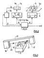
- calculation means 22 are provided for determining, as a function of the quantity supplied by the receiver 18 and of the adjustment position of the head 14 of measurement relative to the object-holder 5, the coordinate of the surface of the object O at point P.
- the calculation means 22 comprise a unit 23 of treatment prescribing adjustment positions R on the one hand by means of displacement 10, 11, 12, 16a of the head 14 and on the other hand to the goniometer 6 of the object holder 5, which move correspondingly.
- the receiver 18 receives the laser beam reflected or passed through the object O with the settings above and provides in response an output quantity G.
- the magnitude G of output from receiver 18 is sent to a memory 24, for example a EPROM or similar memory, where it is saved.
- Processing unit 23 reads the content of the buffer memory 24 to collect the output quantity G of the receiver 18.
- the processing unit calculates, for each adjustment of the head 14 and of the object-holder 5, the coordinate C of the point P of the surface of the object O, from stored adjustment positions R and output quantity G.
- the precision of the means of movement 10, 11, 12, 6, 16a and of the radiation of the laser head 14 is chosen in relation to the desired measurement accuracy.
- the previous operations are repeated for a new adjustment of the head 14 and object holder 5 relative to each other, to determine the coordinate from another point P on the surface of the object O or, where appropriate, the coordinate of the same point P in another direction.
- the size of the memory 24 allows to record for example a certain number N of output quantities G successive, the unit 23 reading the memory 24 every N cycles.
- the unit of processing commands the previous operations for N settings.
- the control of the adjustments of the movement means 10, 11, 12, 6, 16a is such that the object O is continuously scanned along a prescribed path, for example following a plane or other, the laser radiation moving on object O continuously in this plane.
- the output size G of the head 14 is raised by the processing unit 23 at prescribed times, for example every successive instants T during a scan to calculate the coordinates of points P of the object O in the scanning plane.
- Many successive scanning paths, for example successive planes cover a surface of the object. To save even more time, the sweeps are performed back and forth from one end to the other of the object O, these being recognized by any appropriate means.
- the measurement of the coordinate of a first point P on the surface of the object O can then be made by reference to this first measurement.
- the calculated C coordinates are by example provided as an array of numerical values or visualized by a point on a control screen, simulating the surface of the object.
- the coordinates C can be an abscissa, an abscissa and an ordinate, or an abscissa, an ordinate and an altitude, depending on the application envisaged.
- the C coordinates are used for example to determine the surface - envelope of the object O measured. They are also used to verify that the surface of the object O measured remains between two surfaces - envelopes defined by tolerances dimensional and prescribed or determined from the surface - envelope determined or provided beforehand in the previous manner. A room can also be machined from the C coordinates provided beforehand. A one-piece mold with predetermined C coordinates can also to be realized.
- FIG 4 a cross section of a laser beam is shown, showing that the center of the beam 30 is offset from the center of the active area 31 of the laser.
- the different scanning functions are directly linked, at the level of accuracy of acquired points, to the correct positioning of the cell used for make this measurement.
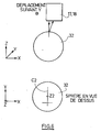
- This coordinate is the top of a calibrated sphere 32, whose diameter is perfectly known, and of a very precise sphericity.
- This sphere 32 may be made of white ceramic in order to limit as much as possible the disturbances due to the brightness of the beam.
- the method thus described applies to a laser pointer consisting of a single laser beam.
- the determination method comprises only the step work along the X axis.
Landscapes
- Physics & Mathematics (AREA)
- General Physics & Mathematics (AREA)
- Length Measuring Devices By Optical Means (AREA)
Abstract
L'invention prévoit un émetteur (17) laser, apte à émettre un rayon laser vers le point (P) de la surface de l'objet (O), un récepteur (18) photosensible apte à transformer le rayon laser réfléchi par l'objet (O) et reçu en une grandeur représentative de la coordonnée (C) à mesurer, des moyens (10, 11, 12, 6, 16a) pour déplacer d'une manière réglable l'ensemble émetteur (17) laser - récepteur (18) photosensible et l'objet (O) à mesurer, et des moyens (22) de calcul de la coordonnée (C) en fonction de la grandeur et de la position (R) de réglage des moyens (10, 11, 12, 6, 16a) de déplacement. <IMAGE>The invention provides a laser transmitter (17) capable of emitting a laser beam towards the point (P) of the surface of the object (O), a photosensitive receiver (18) capable of transforming the laser beam reflected by the object (O) and received in a magnitude representative of the coordinate (C) to be measured, means (10, 11, 12, 6, 16a) for displacing in an adjustable manner the transmitter (17) laser - receiver ( 18) photosensitive and the object (O) to be measured, and means (22) for calculating the coordinate (C) as a function of the magnitude and the position (R) of adjusting the means (10, 11, 12, 6, 16a) of displacement. <IMAGE>
Description
L'invention concerne un dispositif et un procédé pour déterminer au moins une coordonnée d'au moins un point de la surface d'un objet, ainsi que des utilisations de ceux-ci.The invention relates to a device and a method for determining at least one coordinate of at least one point on the surface of an object, as well as uses of these.
L'invention concerne également un procédé de positionnement d'un ensemble émetteur laser - récepteur destiné à déterminer au moins une coordonnée d'au moins un point de la surface d'un objet dans un espace à trois dimensions.The invention also relates to a method for positioning an assembly laser transmitter - receiver intended to determine at least one coordinate of at least minus a point on the surface of an object in three-dimensional space.
L'invention s'applique notamment au contrôle métrologique dimensionnel de précision, mais aussi à la fabrication d'objets en série dont les dimensions doivent rester fidèles à des valeurs précises et au copiage de formes.The invention applies in particular to the dimensional metrological control of precision, but also to the mass production of objects whose dimensions must remain faithful to precise values and to the copying of shapes.
Les applications de ce type nécessitent une mesure à la fois fiable et rapide pour chaque objet. En effet, le temps de mesure doit être multiplié par le nombre de points de l'objet dont la coordonnée doit être mesurée et par le nombre d'objets dont des dimensions sont à mesurer.Applications of this type require both reliable and rapid measurement for each object. Indeed, the measurement time must be multiplied by the number of points of the object whose coordinate is to be measured and by the number of objects whose dimensions are to be measured.
On connaít une mesure par contact mécanique d'une bille roulant sur l'objet à mesurer. Cette mesure peut être précise mais prend au moins plusieurs heures.We know a measurement by mechanical contact of a ball rolling on the object to measure. This measurement can be precise but takes at least several hours.
Actuellement, la mesure de coordonnées de surfaces gauches pose problème avec les moyens classiques, en raison notamment des difficultés d'accès à certaines parties de l'objet pour la mesure.Currently, the measurement of coordinates of left surfaces is problematic with conventional means, in particular due to the difficulties of access to parts of the object for measurement.
En outre, une précision de mesure micrométrique ou submicrométrique est exigée pour certains objets. In addition, micrometric or submicrometric measurement accuracy is required for certain items.
L'invention vise à pallier les inconvénients de l'état de la technique et à obtenir une mesure précise, fiable et rapide de la coordonnée d'un point de la surface d'un objet.The invention aims to overcome the drawbacks of the state of the art and to obtain precise, reliable and fast measurement of the coordinate of a point on the surface of an object.
Suivant un premier aspect de l'invention, il est prévu un dispositif de mesure de la coordonnée d'au moins un point de la surface d'un objet, comportant :
- des premiers moyens de support d'un objet,
- au moins un émetteur laser, apte à émettre au moins un rayon laser vers le point de la surface de l'objet,
- au moins un récepteur photosensible orienté vers l'objet et apte à transformer le rayon laser réfléchi par l'objet ou passé par celui-ci et reçu en une grandeur représentative d'une dimension,
- des deuxièmes moyens de support de l'émetteur laser et du récepteur photosensible,
- des moyens pour déplacer d'une manière réglable l'ensemble émetteur laser - récepteur photosensible d'une part et l'objet d'autre part l'un par rapport à l'autre,
- des moyens de calcul de la coordonnée du point de la surface de l'objet en fonction de la grandeur fournie par le récepteur et de la position de réglage des moyens de déplacement.
- first means of supporting an object,
- at least one laser emitter, capable of emitting at least one laser beam towards the point on the surface of the object,
- at least one photosensitive receiver oriented towards the object and capable of transforming the laser beam reflected by the object or passed through it and received into a quantity representative of a dimension,
- second means for supporting the laser transmitter and the photosensitive receiver,
- means for moving the laser emitter - photosensitive receiver unit on the one hand and the object on the other relative to each other in an adjustable manner,
- means for calculating the coordinate of the point on the surface of the object as a function of the quantity supplied by the receiver and of the position of adjustment of the displacement means.
Ce dispositif permet d'effectuer des mesures de coordonnées de manière précisément reproductible et répétitive, notamment d'un grand nombre d'objets à surfaces gauches, tout en diminuant le temps pour ce faire.This device makes it possible to perform coordinate measurements in a manner precisely reproducible and repetitive, including a large number of objects on left surfaces, while reducing the time to do so.
Afin de pouvoir balayer de manière rationnelle la surface de l'objet à mesurer, les moyens de déplacement sont aptes, suivant une caractéristique de l'invention, à régler la position de l'ensemble émetteur laser - récepteur photosensible suivant trois directions orthonormées et comprennent un goniomètre pour le réglage en position de l'objet à mesurer autour de deux axes orthogonaux par rapport au bâti. In order to be able to rationally scan the surface of the object to be measured, the displacement means are suitable, according to a characteristic of the invention, to adjust the position of the laser transmitter - receiver assembly photosensitive in three orthonormal directions and include a goniometer for adjusting the position of the object to be measured around two axes orthogonal to the frame.
Suivant une autre caractéristique de l'invention, il est prévu des moyens pour régler la position angulaire de l'ensemble émetteur laser - récepteur photosensible autour d'un axe de rotation par rapport au bâti.According to another characteristic of the invention, means are provided for adjust the angular position of the laser transmitter - receiver assembly photosensitive about an axis of rotation relative to the frame.
Le fait que les axes de réglage angulaire du goniomètre sont concourants en un même centre permet de simplifier les moyens de calcul.The fact that the angular adjustment axes of the goniometer are concurrent in a same center simplifies the means of calculation.
Dans un mode de réalisation, le récepteur photosensible comprend une diode photosensible dont la zone de réception de rayonnement laser possède une étendue suffisante pour être balayée par le rayon laser réfléchi ou passé par l'objet à mesurer et fournissant en sortie une différence de potentiel ou de courant électrique fonction du rayonnement reçu dans la zone de réception.In one embodiment, the photosensitive receiver includes a diode photosensitive whose laser radiation receiving area has a sufficient area to be scanned by the reflected or passed laser beam the object to be measured and providing a difference in potential or electric current depending on the radiation received in the reception area.
Dans une première variante de l'invention, l'ensemble émetteur laser-récepteur photosensible est agencé de manière que l'incidence du rayon laser sur le point de la surface de l'objet possède une composante parallèle à la direction suivant laquelle la coordonnée doit être déterminée et que le récepteur photosensible reçoive le rayon laser réfléchi par l'objet.In a first variant of the invention, the laser transmitter-receiver assembly photosensitive is arranged so that the incidence of the laser beam on the point of the object's surface has a component parallel to the direction in which the coordinate should be determined and that the receiver photosensitive receives the laser beam reflected by the object.
Dans une deuxième variante de l'invention, l'ensemble émetteur laser-récepteur photosensible est agencé de manière que l'incidence du rayon laser sur le point de la surface de l'objet possède une composante orthogonale à la direction suivant laquelle la coordonnée de l'objet doit être déterminée et que le récepteur photosensible reçoive le rayon laser passé par l'objet.In a second variant of the invention, the laser transmitter-receiver assembly photosensitive is arranged so that the incidence of the laser beam on the point of the object's surface has a component orthogonal to the direction in which the coordinate of the object must be determined and that the photosensitive receiver receives the laser beam passed through the object.
Afin de mesurer la coordonnée d'un ensemble de points de la surface de l'objet, les moyens de calcul comprennent une unité de traitement apte à commander en continu des positions de réglages des moyens de déplacement, à recueillir en continu la grandeur fournie par le récepteur et à calculer à partir de ces positions de réglage et des grandeurs fournies une coordonnée de point de la surface de l'objet pour chaque réglage. In order to measure the coordinate of a set of points on the surface of the object, the calculation means include a processing unit capable of controlling continuously adjustment positions of the displacement means, to be collected continuously the quantity supplied by the receiver and to be calculated from these adjustment positions and quantities provided a point coordinate of the object surface for each setting.
Pour une plus grande rapidité de calcul, une mémoire est prévue entre le récepteur photosensible et l'unité de traitement pour stocker les grandeurs fournies par le récepteur photosensible.For faster calculation, a memory is provided between the photosensitive receiver and processing unit for storing quantities supplied by the photosensitive receiver.
Suivant un deuxième aspect de l'invention, il est prévu un procédé de détermination d'au moins une coordonnée d'au moins un point de la surface d'un objet, dans lequel
- on règle d'une manière prescrite la position l'un par rapport à l'autre d'un ensemble émetteur laser - récepteur photosensible d'une part et de l'objet à mesurer d'autre part,
- on émet au moins un rayon laser vers le point de la surface de l'objet par l'émetteur laser,
- on transforme par un récepteur photosensible orienté vers l'objet le rayon laser réfléchi ou passé par l'objet et reçu en une grandeur représentative d'une dimension,
- on calcule la coordonnée du point de la surface de l'objet en fonction de la grandeur représentative et de la position de réglage prescrite l'un par rapport à l'autre de l'ensemble émetteur laser - récepteur photosensible d'une part et de l'objet à mesurer d'autre part.
- the position relative to one another of a laser transmitter-photosensitive receiver unit on the one hand and of the object to be measured on the other hand is adjusted in a prescribed manner
- at least one laser beam is emitted towards the point of the surface of the object by the laser transmitter,
- the laser beam reflected or passed by the object and received into a quantity representative of a dimension is transformed by a photosensitive receiver oriented towards the object,
- the coordinate of the point on the surface of the object is calculated as a function of the representative quantity and of the prescribed adjustment position relative to one another of the laser transmitter-photosensitive receiver assembly on the one hand and the object to be measured on the other hand.
Suivant une caractéristique de l'invention, l'on étalonne au préalable le récepteur photosensible afin de déterminer sa courbe de dimension correspondant à la grandeur fournie par celui-ci. Ceci permet de calculer automatiquement la coordonnée.According to a characteristic of the invention, the photosensitive receiver to determine its dimension curve corresponding to the quantity provided by it. This allows you to calculate the coordinate automatically.
Suivant une autre caractéristique de l'invention, l'on règle la position de l'ensemble émetteur laser - récepteur photosensible suivant trois directions orthonormées ainsi que sa position angulaire autour d'un axe de rotation et l'on règle la position angulaire de l'objet à mesurer autour de deux axes orthogonaux.According to another characteristic of the invention, the position of the laser transmitter - photosensitive receiver assembly in three directions orthonormal as well as its angular position around an axis of rotation and one adjusts the angular position of the object to be measured around two axes orthogonal.
Dans une première variante de l'invention, l'on oriente l'ensemble émetteur laser - récepteur photosensible de manière que l'incidence du rayon laser sur le point de la surface de l'objet possède une composante parallèle à la direction suivant laquelle la coordonnée de l'objet doit être déterminée et que le récepteur photosensible reçoive le rayon laser réfléchi par l'objet.In a first variant of the invention, the transmitter assembly is oriented laser - photosensitive receiver so that the incidence of the laser beam on the point on the surface of the object has a component parallel to the direction according to which the coordinate of the object must be determined and that the photosensitive receiver receives the laser beam reflected by the object.
Dans une deuxième variante de l'invention, l'on oriente l'ensemble émetteur laser - récepteur photosensible de manière que l'incidence du rayon laser sur le point de la surface de l'objet possède une composante orthogonale à la direction suivant laquelle la coordonnée de l'objet doit être déterminée et que le récepteur photosensible reçoive le rayon laser passé par l'objet.In a second variant of the invention, the transmitter assembly is oriented laser - photosensitive receiver so that the incidence of the laser beam on the point on the surface of the object has a component orthogonal to the direction in which the coordinate of the object must be determined and that the photosensitive receiver receives the laser beam passed through the object.
Afin de déterminer la coordonnée d'un ensemble de points de la surface de l'objet, l'on commande en continu les positions de réglage l'un par rapport à l'autre de l'ensemble émetteur laser - récepteur photosensible et de l'objet à mesurer, on recueille en continu la grandeur fournie par le récepteur et on calcule à partir de ces positions de réglage et des grandeurs fournies une coordonnée d'un point de la surface de l'objet pour chaque réglage.In order to determine the coordinate of a set of points on the surface of the object, the adjustment positions are continuously controlled, one with respect to the other of the laser transmitter-photosensitive receiver and of the object to be measure, the quantity supplied by the receiver is continuously collected and calculates from these adjustment positions and the quantities provided a coordinate of a point on the surface of the object for each adjustment.
Suivant une caractéristique de l'invention, l'on stocke les grandeurs fournies par le récepteur photosensible avant le calcul de la coordonnée de l'objet.According to a characteristic of the invention, the quantities supplied by the photosensitive receiver before calculating the coordinate of the object.
L'invention prévoit également l'utilisation d'un dispositif de mesure ou d'un procédé de mesure mentionnés ci-dessus pour déterminer la surface-enveloppe d'un objet.The invention also provides for the use of a measuring device or a above-mentioned measurement method for determining the surface-envelope of an object.
Dans une autre application de l'invention, il est prévu l'utilisation d'un dispositif de mesure ou d'un procédé de mesure mentionnés ci-dessus pour vérifier que la surface d'un objet reste entre deux surfaces - enveloppes définies par des tolérances dimensionnelles.In another application of the invention, provision is made for the use of a device above mentioned measurement method or process to verify that the surface of an object remains between two surfaces - envelopes defined by dimensional tolerances.
Une autre application de l'invention prévoit l'utilisation d'un dispositif de mesure ou d'un procédé de mesure mentionnés ci-dessus pour usiner une pièce à partir de coordonnées fournies au préalable par le dispositif ou le procédé. Another application of the invention provides for the use of a measuring device or a measurement method mentioned above to machine a part from contact details provided beforehand by the device or process.
Une autre application de l'invention prévoit l'utilisation d'un dispositif de mesure ou d'un procédé de mesure mentionnés ci-dessus pour réaliser un moule d'une pièce ayant des coordonnées fournies au préalable par le dispositif ou le procédé.Another application of the invention provides for the use of a measuring device or a measurement method mentioned above to make a mold of part with contact details provided beforehand by the device or process.
Suivant un troisième aspect de l'invention, il est prévu un procédé de positionnement d'un ensemble émetteur laser- récepteur.According to a third aspect of the invention, there is provided a method of positioning of a laser transmitter-receiver assembly.
En effet, un faisceau laser se comporte comme un ensemble de « fibres » lumineuses et, dans les applications métrologiques précédemment décrites, seul un nombre restreint de ces fibres sont actives, c'est à dire participent au relevé des coordonnées désirées.Indeed, a laser beam behaves like a set of "fibers" luminous and, in the metrological applications previously described, only a limited number of these fibers are active, i.e. participate in the statement of the desired coordinates.
Dans un faisceau laser, on peut donc isoler une sorte de sous-faisceau actif, l'axe longitudinal du sous-faisceau étant parallèle à l'axe longitudinal du faisceau principal mais ces deux axes sont aléatoirement décalé l'un par rapport à l'autre.In a laser beam, we can therefore isolate a kind of active sub-beam, the longitudinal axis of the sub-beam being parallel to the longitudinal axis of the main beam but these two axes are randomly shifted one by compared to each other.
Ceci induit une erreur constante dans les mesures (la distance séparant les deux axes évoqués), à laquelle il est possible de remédier en déterminant la position du sous-faisceau actif à l'intérieur d'un faisceau laser, puis en positionnant l'ensemble émetteur laser - récepteur de manière à tenir compte du décalage entre les axes du faisceau principal et du sous-faisceau actif.This induces a constant error in the measurements (the distance between the two axes mentioned), which can be remedied by determining the position of the active sub-beam inside a laser beam, then in positioning the laser transmitter - receiver assembly so as to take into account the offset between the axes of the main beam and the active sub-beam.
A cet effet, l'invention propose un procédé de positionnement d'un ensemble
émetteur laser - récepteur destiné à déterminer au moins une coordonnée d'au
moins un point de la surface d'un objet dans un espace à trois dimensions (X,
Y, Z), et comprenant les étapes suivantes :
L'invention sera mieux comprise à la lumière des dessins annexés, donnés uniquement à titre d'exemples, sur lesquels :
- la figure 1 est une vue schématique en perspective d'un dispositif de mesure suivant l'invention ;
- la figure 2 est un synoptique modulaire de la logique de commande du dispositif de mesure selon la figure 1 ;
- la figure 3 est une vue schématique d'une variante du dispositif de mesure selon l'invention ;
- la figure 4 est une vue schématique d'une section de faisceau laser ;
- la figure 5 est un schéma représentant l'une des étapes du procédé de positionnement selon l'invention ;
- la figure 6 est un schéma représentant une autre étape du prod=cédé de positionnement selon l'invention.
- Figure 1 is a schematic perspective view of a measuring device according to the invention;
- Figure 2 is a modular block diagram of the control logic of the measuring device according to Figure 1;
- Figure 3 is a schematic view of a variant of the measuring device according to the invention;
- Figure 4 is a schematic view of a laser beam section;
- FIG. 5 is a diagram representing one of the steps of the positioning method according to the invention;
- FIG. 6 is a diagram representing another step of the positioning product according to the invention.
A la figure 1, le dispositif de mesure 1 comporte une table 2 horizontale ou un
bâti de support d'une platine 3 prévue pour y immobiliser l'objet O à mesurer. In FIG. 1, the measuring
La platine 3 comporte un châssis 4 mobile en rotation autour d'un axe vertical
Z1 par rapport à la table et un porte-objet 5 mobile en rotation autour d'un axe
X1 horizontal par rapport au châssis 4. Un goniomètre 6 permet de régler d'une
manière prescrite les positions angulaires du porte-objet 5 par rapport à la table
2. Les axes X1 et Z1 sont concourants. Bien entendu, la table peut avoir toute
autre position, par exemple une position verticale.The plate 3 comprises a chassis 4 movable in rotation about a vertical axis
Z1 relative to the table and an
Un pilier vertical 7 supportant est monté mobile en translation par rapport à la
table 2 suivant une direction Y horizontale perpendiculaire à la direction X1
horizontale. Une traverse 8 est montée mobile en translation dans le sens de sa
longueur suivant une direction X horizontale parallèle à la direction X1. Un
portique non représenté peut également être prévu sur la table 2 au lieu du
pilier 7 et de la traverse 8.A
Un bras 9 vertical est monté mobile dans le sens de sa longueur sur la traverse
8 suivant une direction Z verticale parallèle à la direction Z1. Des moyens de
déplacement 10, 11, 12 du pilier 7, de la traverse 8 et du bras 9 selon leur
degré de liberté respectif Y, X et Z par rapport à la table 2, au pilier 7 et à la
traverse 8 sont prévus sur ces derniers. Les moyens de déplacement 10, 11, 12
peuvent être commandés pour obtenir des coordonnées prescrites en X, Y, Z
du bras 9 par rapport à la table 2.A vertical arm 9 is mounted movable in the direction of its length on the crosspiece
8 in a vertical direction Z parallel to the direction Z1. Means of
Une tête 14 de mesure est montée sur la partie extrême 15 du bras 9, tournée
vers la table 2. La tête 14 est articulée en rotation autour d'un axe d'articulation
16 parallèle à la direction Y. Des moyens réglables 16a de déplacement de la
position angulaire autour de l'axe 16 de la tête 14 par rapport à la partie
extrême 15 du bras 9 sont prévus. Dans d'autres réalisations, non
représentées, la tête de mesure est montée fixe sur le bras, tandis que le porte-objet
est mobile en rotation autour de trois axes orthonormés. Les trois axes de
translation et les trois axes de rotation peuvent également être prévus en partie
ou entièrement sur la tête ou sur le porte-objet. Dans d'autres réalisations, non
représentées, les axes par rapport auxquels sont effectués les translations
et/ou les rotations ne sont pas orthonormés, tout en définissant un système de
coordonnées dans l'espace à trois dimensions, permettant toute orientation
directionnelle de la tête dans celui-ci.A measuring
La tête 14 comporte un émetteur laser 17, par exemple sous forme de diode
laser, et un récepteur photosensible 18, par exemple sous forme de diode
photosensible. L'émetteur 17 et le récepteur 18 sont fixes l'un par rapport à
l'autre. L'émetteur 17 émet un rayon laser focalisé dans une direction 19 fixe
par rapport à la tête 14. Le récepteur 18 est apte à transformer le rayon laser
réfléchi par l'objet ou passé par celui-ci et reçu en une grandeur représentative
d'une dimension. Le récepteur 18 comprend une zone 20 photosensible de
réception ayant une certaine étendue, transversale à la direction 19 du rayon
laser et tournée vers l'extérieur. Une différence de potentiel ou un courant
électrique est produit à la sortie du récepteur 18 en fonction de la partie de la
zone 20 de réception, qui est effectivement atteinte par un rayonnement laser.
La caractéristique du récepteur grandeur de sortie - coordonnée de la partie de
zone 20, atteinte par le rayonnement laser, est déterminée lors d'un étalonnage
préalable. L'étendue de la zone 20 de réception est suffisante pour être balayée
par le rayon laser réfléchi ou passé par l'objet O à mesurer.The
A la figure 1, le rayon laser émis par l'émetteur 17 est dirigé suivant la direction
incidente 19 sur le point P de la surface de l'objet O dont la coordonnée doit
être mesurée. Le récepteur 18 et l'émetteur 17 sont côte à côte sur la tête. La
tête est formée par exemple d'un pointeur laser. La tête est orientée de manière
que la zone de réception 18 reçoive le rayon laser réfléchi par l'objet au point P,
et que le rayon laser ne soit pas dirigé suivant la normale à la surface de l'objet
O au point P. L'incidence du rayon laser sur le point P de la surface de l'objet
possède une composante parallèle à la direction suivant laquelle la coordonnée
doit être mesurée. Un déplacement de l'objet O par rapport à la tête 14 suivant
la direction 19 du rayon incident entraíne ainsi un déplacement de la partie
éclairée par le rayon réfléchi sur la zone 20 de réception, provoquant un
changement de la grandeur de sortie du récepteur 18. In FIG. 1, the laser beam emitted by the
A la figure 3, la tête 14 est agencée de manière que la zone de réception 20
reçoive le rayonnement laser passé par l'objet. L'émetteur 17 et le récepteur 18
se trouvent de part et d'autre de l'objet O à mesurer et du porte-objet 5, et sont
immobilisés l'un par rapport à l'autre par l'intermédiaire d'une barrette de
fixation à laquelle ils sont fixés et elle-même fixée à la partie extrême 15 du
bras 9. L'objet O intercepte une partie de la nappe 21 de rayonnement laser
émise par l'émetteur 17 et en laisse passer une autre partie jusqu'à la zone 20
de réception. L'incidence du rayon laser sur le point de la surface de l'objet
possède une composante orthogonale à la direction suivant laquelle la
coordonnée de l'objet doit être mesurée. Le déplacement de l'objet O et du
porte-objet 5 perpendiculairement à la direction 19 d'émission du rayonnement
laser provoque un déplacement de la partie de la zone 20 de réception éclairée
par celui-ci, provoquant un changement de la grandeur de sortie du récepteur
18.In FIG. 3, the
A la figure 2, des moyens 22 de calcul sont prévus pour déterminer, en fonction
de la grandeur fournie par le récepteur 18 et de la position de réglage de la tête
14 de mesure par rapport au porte-objet 5, la coordonnée de la surface de
l'objet O au point P. Les moyens 22 de calcul comprennent une unité 23 de
traitement prescrivant des positions R de réglage d'une part aux moyens de
déplacement 10, 11, 12, 16a de la tête 14 et d'autre part au goniomètre 6 du
porte-objet 5, qui se meuvent de manière correspondante. Le récepteur 18
reçoit le rayon laser réfléchi ou passé par l'objet O avec les réglages
précédents et fournit en réponse une grandeur G de sortie. La grandeur G de
sortie du récepteur 18 est envoyée à une mémoire 24, par exemple une
mémoire EPROM ou similaire, où elle est enregistrée. L'unité 23 de traitement
lit le contenu de la mémoire tampon 24 pour recueillir la grandeur G de sortie du
récepteur 18. L'unité de traitement calcule, pour chaque réglage de la tête 14 et
du porte-objet 5, la coordonnée C du point P de la surface de l'objet O, à partir
des positions R de réglage mémorisées et de la grandeur G de sortie. La
précision des moyens de déplacements 10, 11, 12, 6, 16a et du rayonnement
de la tête laser 14 est choisie en rapport avec la précision de mesure souhaitée. In FIG. 2, calculation means 22 are provided for determining, as a function
of the quantity supplied by the
Les opérations précédentes sont répétées pour un nouveau réglage de la tête
14 et du porte-objet 5 l'un par rapport à l'autre, pour déterminer la coordonnée
d'un autre point P de la surface de l'objet O ou le cas échéant la coordonnée du
même point P suivant une autre direction. La taille de la mémoire 24 permet
d'enregistrer par exemple un certain nombre N de grandeurs G de sortie
successives, l'unité 23 lisant la mémoire 24 tous les N cycles. L'unité de
traitement commande les opérations précédentes pour N réglages.The previous operations are repeated for a new adjustment of the
La commande des réglages des moyens de déplacements 10, 11, 12, 6, 16a
est telle que l'objet O soit balayé en continu suivant une trajectoire prescrite,
par exemple suivant un plan ou autre, le rayonnement laser se déplaçant sur
l'objet O de manière continue dans ce plan. La grandeur G de sortie de la tête
14 est relevée par l'unité 23 de traitement à des instants prescrits, par exemple
tous les instants T successifs au cours d'un balayage pour calculer les
coordonnées de points P de l'objet O dans le plan de balayage. Plusieurs
trajectoires successives de balayage, par exemple des plans successifs,
permettent de couvrir une surface de l'objet. Pour gagner encore du temps, les
balayages sont effectués en aller-retour d'une extrémité à l'autre de l'objet O,
celles-ci étant reconnues par tout moyen approprié.The control of the adjustments of the movement means 10, 11, 12, 6, 16a
is such that the object O is continuously scanned along a prescribed path,
for example following a plane or other, the laser radiation moving on
object O continuously in this plane. The output size G of the
Au cours d'une opération d'étalonnage préalable, on effectue la mesure de la coordonnée d'un premier point P de la surface de l'objet O. Les mesures suivantes de coordonnées du même objet O pourront alors être effectuées en référence à cette première mesure. Les coordonnées C calculées sont par exemple fournies sous forme d'un tableau de valeurs numériques ou visualisées par un point sur un écran de contrôle, simulant la surface de l'objet.During a preliminary calibration operation, the measurement of the coordinate of a first point P on the surface of the object O. The measurements following coordinates of the same object O can then be made by reference to this first measurement. The calculated C coordinates are by example provided as an array of numerical values or visualized by a point on a control screen, simulating the surface of the object.
Les coordonnées C peuvent être une abscisse, une abscisse et une ordonnée, ou une abscisse, une ordonnée et une altitude, selon l'application envisagée.The coordinates C can be an abscissa, an abscissa and an ordinate, or an abscissa, an ordinate and an altitude, depending on the application envisaged.
Les coordonnées C servent par exemple à déterminer la surface - enveloppe de l'objet O mesuré. Elles servent également à vérifier que la surface de l'objet O mesuré reste entre deux surfaces - enveloppes définies par des tolérances dimensionnelles et prescrites ou déterminées à partir de la surface - enveloppe déterminée ou fournie au préalable de la manière précédente. Une pièce peut également être usinée à partir des coordonnées C fournies au préalable. Un moule d'une pièce ayant les coordonnées C prédéterminées peut également être réalisé.The C coordinates are used for example to determine the surface - envelope of the object O measured. They are also used to verify that the surface of the object O measured remains between two surfaces - envelopes defined by tolerances dimensional and prescribed or determined from the surface - envelope determined or provided beforehand in the previous manner. A room can also be machined from the C coordinates provided beforehand. A one-piece mold with predetermined C coordinates can also to be realized.
Enfin, le procédé de positionnement d'un ensemble émetteur laser - récepteur va maintenant être décrit.Finally, the positioning process of a laser transmitter - receiver assembly will now be described.
A la figure 4, une section droite d'un faisceau laser est représentée, montrant
que le centre du faisceau 30 est décalé par rapport au centre de la zone active
31 du laser.In Figure 4, a cross section of a laser beam is shown, showing
that the center of the
Les différentes fonctions de scanning, sont directement liées , au niveau de la précision des points acquis, au bon positionnement de la cellule utilisée pour faire cette mesure.The different scanning functions are directly linked, at the level of accuracy of acquired points, to the correct positioning of the cell used for make this measurement.
Il est souhaitable, afin de garantir la fiabilité des mesures, de positionner de manière correcte, le spot émis par le laser. Cette opération est très délicate, voir impossible. C'est pourquoi, plutôt que de positionner le spot de manière aléatoire, il est plus judicieux d'apprendre à la cellule où elle doit être positionnée.In order to guarantee the reliability of the measurements, it is desirable to position correctly, the spot emitted by the laser. This operation is very delicate, see impossible. This is why, rather than positioning the spot so random it makes more sense to teach the cell where it should be positioned.
Dans le cadre de cet apprentissage, il est nécessaire de positionner la zone
« active» du faisceau laser sur une coordonnée connue. Cette coordonnée est
le sommet d'une sphère 32 calibrée, dont on connaít parfaitement le diamètre,
et d'une sphéricité des plus précises.As part of this learning, it is necessary to position the area
"Active" of the laser beam on a known coordinate. This coordinate is
the top of a calibrated
Cette sphère 32 peut-être en céramique blanche afin de limiter au maximum les
perturbations dues à l'éclat du faisceau.This
Afin de déterminer avec précision la localisation de la partie « active » du
faisceau, il est procédé comme suit:
Cette mesure est en fait l'acquisition des différents points de digitalisation constituant l'arc de cercle C1. Ces différents points sont traités via l'informatique de telle façon à satisfaire l'équation d'une "Best Fit" (Equation du cercle avec traitement des résultats par la méthode des moindre carrés par exemple).
De cette équation, on tire les coordonnées point théorique Z1 ayant sa coordonnée suivant Z au maximum.
This measurement is in fact the acquisition of the different digitization points constituting the arc of a circle C1. These various points are treated via data processing in such a way as to satisfy the equation of a "Best Fit" (Equation of the circle with treatment of the results by the method of the least squares for example).
From this equation, the theoretical point coordinates Z1 having its maximum Z coordinate are drawn.
Ces trois étapes franchies, les déplacements machines et laser sont en phase et travaillent suivant le même repère.Once these three stages have been completed, the machine and laser movements are in phase and work according to the same benchmark.
En suivant le même procédé de réglage, par mesure successives de différentes sphères, il est possible d'établir avec la plus grande précision un volume de rotation, dont on connaít parfaitement le centre ainsi que le rayon.By following the same adjustment process, by successive measurement of different spheres, it is possible to establish with the greatest precision a volume of rotation, which we know perfectly the center and the radius.
Le procédé ainsi décrit s'applique à un pointeur laser constitué d'un seul faisceau laser. The method thus described applies to a laser pointer consisting of a single laser beam.
Dans le cas d'une nappe laser (ayant une épaisseur de l'ordre du millimètre par exemple) le procédé de détermination comprend seulement l'étape mise en oeuvre selon l'axe X.In the case of a laser sheet (having a thickness of the order of a millimeter per example) the determination method comprises only the step work along the X axis.
Claims (21)
Applications Claiming Priority (2)
| Application Number | Priority Date | Filing Date | Title |
|---|---|---|---|
| FR0012670 | 2000-10-04 | ||
| FR0012670A FR2814807B1 (en) | 2000-10-04 | 2000-10-04 | DEVICE AND METHOD FOR DETERMINING SURFACE COORDINATES AND USES THEREOF |
Publications (1)
| Publication Number | Publication Date |
|---|---|
| EP1195575A1 true EP1195575A1 (en) | 2002-04-10 |
Family
ID=8854988
Family Applications (1)
| Application Number | Title | Priority Date | Filing Date |
|---|---|---|---|
| EP01402559A Withdrawn EP1195575A1 (en) | 2000-10-04 | 2001-10-04 | Procedure and device to determine surface coordinates and their application and positioning procedure for a laser emitter-detector |
Country Status (2)
| Country | Link |
|---|---|
| EP (1) | EP1195575A1 (en) |
| FR (1) | FR2814807B1 (en) |
Cited By (4)
| Publication number | Priority date | Publication date | Assignee | Title |
|---|---|---|---|---|
| EP1609437A1 (en) * | 2004-06-24 | 2005-12-28 | KCI Co., Ltd | Driving apparatus for three-dimensional scanning system and three-dimensional scanning system for computer-aided tooth modelling using the same |
| CN100387931C (en) * | 2006-04-28 | 2008-05-14 | 南通大学 | Wide range and high precision free curved surface measuring method |
| US9086272B2 (en) | 2010-10-27 | 2015-07-21 | Nikon Corporation | Profile measuring apparatus, method for manufacturing structure, and structure manufacturing system |
| CN106969709A (en) * | 2017-05-03 | 2017-07-21 | 温州职业技术学院 | A kind of detection means of blood taking needle automatic assembling |
Families Citing this family (1)
| Publication number | Priority date | Publication date | Assignee | Title |
|---|---|---|---|---|
| CN106908802B (en) * | 2017-03-07 | 2023-09-05 | 长安大学 | Laser beam space positioning device and method based on image processing |
Citations (10)
| Publication number | Priority date | Publication date | Assignee | Title |
|---|---|---|---|---|
| FR2551860A1 (en) * | 1983-09-08 | 1985-03-15 | Sciaky Sa | INSTALLATION FOR DETERMINING SPACE COORDINATES OF A POINT OF A WORKPIECE, IN PARTICULAR FOR CONTROLLING A TOOLING SUCH AS A BODY WELDING TOOL FOR A MOTOR VEHICLE |
| EP0234007A1 (en) * | 1985-12-10 | 1987-09-02 | Chuo Electric Manufacturing Co., Ltd. | Noncontact measuring device for cylindrical, elongated objects bent into three-dimensional shapes |
| US4743770A (en) * | 1986-09-22 | 1988-05-10 | Mitutoyo Mfg. Co., Ltd. | Profile-measuring light probe using a change in reflection factor in the proximity of a critical angle of light |
| JPH01318904A (en) * | 1988-06-21 | 1989-12-25 | Agency Of Ind Science & Technol | Method for three-dimensional measurement by spherical mapping |
| EP0395811A2 (en) * | 1989-05-02 | 1990-11-07 | Eaton Leonard, Inc. | Optical probe |
| DE4208455A1 (en) * | 1992-03-17 | 1993-09-23 | Peter Dr Ing Brueckner | Contactless three=dimensional measurement e.g of teeth - using opto-electronic measurement in two dimensions and rotative or translation in third dimension and combining w.r.t actual position of measurement planes |
| US5446798A (en) * | 1989-06-20 | 1995-08-29 | Fujitsu Limited | Method and apparatus for measuring position and orientation of an object based on a sequence of projected points |
| US5760906A (en) * | 1995-12-27 | 1998-06-02 | Technology Research Association Of Medical And Welfare Apparatus | Shape measurement apparatus and method |
| EP0913130A2 (en) * | 1997-10-31 | 1999-05-06 | DCS Forschungs & Entwicklungs AG | Method and device for manufacturing a dental prosthesis |
| US5938446A (en) * | 1994-10-04 | 1999-08-17 | Nobel Biocare Ab | Method and device for a product intended to be introduced into the human body, and scanning device for a model of the product |
-
2000
- 2000-10-04 FR FR0012670A patent/FR2814807B1/en not_active Expired - Fee Related
-
2001
- 2001-10-04 EP EP01402559A patent/EP1195575A1/en not_active Withdrawn
Patent Citations (10)
| Publication number | Priority date | Publication date | Assignee | Title |
|---|---|---|---|---|
| FR2551860A1 (en) * | 1983-09-08 | 1985-03-15 | Sciaky Sa | INSTALLATION FOR DETERMINING SPACE COORDINATES OF A POINT OF A WORKPIECE, IN PARTICULAR FOR CONTROLLING A TOOLING SUCH AS A BODY WELDING TOOL FOR A MOTOR VEHICLE |
| EP0234007A1 (en) * | 1985-12-10 | 1987-09-02 | Chuo Electric Manufacturing Co., Ltd. | Noncontact measuring device for cylindrical, elongated objects bent into three-dimensional shapes |
| US4743770A (en) * | 1986-09-22 | 1988-05-10 | Mitutoyo Mfg. Co., Ltd. | Profile-measuring light probe using a change in reflection factor in the proximity of a critical angle of light |
| JPH01318904A (en) * | 1988-06-21 | 1989-12-25 | Agency Of Ind Science & Technol | Method for three-dimensional measurement by spherical mapping |
| EP0395811A2 (en) * | 1989-05-02 | 1990-11-07 | Eaton Leonard, Inc. | Optical probe |
| US5446798A (en) * | 1989-06-20 | 1995-08-29 | Fujitsu Limited | Method and apparatus for measuring position and orientation of an object based on a sequence of projected points |
| DE4208455A1 (en) * | 1992-03-17 | 1993-09-23 | Peter Dr Ing Brueckner | Contactless three=dimensional measurement e.g of teeth - using opto-electronic measurement in two dimensions and rotative or translation in third dimension and combining w.r.t actual position of measurement planes |
| US5938446A (en) * | 1994-10-04 | 1999-08-17 | Nobel Biocare Ab | Method and device for a product intended to be introduced into the human body, and scanning device for a model of the product |
| US5760906A (en) * | 1995-12-27 | 1998-06-02 | Technology Research Association Of Medical And Welfare Apparatus | Shape measurement apparatus and method |
| EP0913130A2 (en) * | 1997-10-31 | 1999-05-06 | DCS Forschungs & Entwicklungs AG | Method and device for manufacturing a dental prosthesis |
Cited By (6)
| Publication number | Priority date | Publication date | Assignee | Title |
|---|---|---|---|---|
| EP1609437A1 (en) * | 2004-06-24 | 2005-12-28 | KCI Co., Ltd | Driving apparatus for three-dimensional scanning system and three-dimensional scanning system for computer-aided tooth modelling using the same |
| CN100387931C (en) * | 2006-04-28 | 2008-05-14 | 南通大学 | Wide range and high precision free curved surface measuring method |
| US9086272B2 (en) | 2010-10-27 | 2015-07-21 | Nikon Corporation | Profile measuring apparatus, method for manufacturing structure, and structure manufacturing system |
| EP2633268B1 (en) * | 2010-10-27 | 2018-09-26 | Nikon Corporation | Profile measuring apparatus and method for manufacturing a structure. |
| CN106969709A (en) * | 2017-05-03 | 2017-07-21 | 温州职业技术学院 | A kind of detection means of blood taking needle automatic assembling |
| CN106969709B (en) * | 2017-05-03 | 2022-11-01 | 温州职业技术学院 | Detection apparatus for automatic kludge of blood taking needle |
Also Published As
| Publication number | Publication date |
|---|---|
| FR2814807B1 (en) | 2003-01-03 |
| FR2814807A1 (en) | 2002-04-05 |
Similar Documents
| Publication | Publication Date | Title |
|---|---|---|
| EP1209441B1 (en) | Three-dimensional shape-measuring instrument with laser scanner | |
| EP1733181B1 (en) | Mixed optical and mechanical sensor and associated resetting method | |
| EP0452422B1 (en) | Method for calibrating a system for the tri-dimensional acquisition of shape and system for implementing such method | |
| EP0279730B1 (en) | Method and device for tridimensional measurement | |
| FR2916534A1 (en) | METHOD AND DEVICE FOR NON-CONTACT MEASUREMENT OF OSCILLATIONS OF AN OBJECT | |
| JP2011526375A (en) | Optical inspection probe | |
| EP0766063B1 (en) | Lens parameter measurement using optical sectioning | |
| FR2664043A1 (en) | VARIABLE MAGNIFICATION LENS FOR A VARIABLE DEPTH OF FIELD SHOOTING APPARATUS. | |
| EP0320326B1 (en) | Process and means for contactless controlling the geometric outlines | |
| FR2658286A1 (en) | APPARATUS FOR DETERMINING THE CONFIGURATION OF A ROTATING MOUNTED BODY ON A SHAFT AND ASSOCIATED METHOD. | |
| FR2664042A1 (en) | SPOT DIMENSION CONTROLLER FOR A VARIABLE DEPTH OF FIELD SHOOTING APPARATUS. | |
| EP0600800A1 (en) | Procedure and device to acquire an image, in three dimensions, of a small object with a light pencil and a calibration method for such an acquirement | |
| JPH09507576A (en) | Method and apparatus for measuring eccentric rotating components | |
| EP0647829B1 (en) | Process and device for the geometrical control of a vehicle | |
| EP1674822A1 (en) | Device and method for non-contact scanning of contact lens mold geometry | |
| EP0662211B1 (en) | Method and apparatus for measuring the dimensions of an object | |
| EP1195575A1 (en) | Procedure and device to determine surface coordinates and their application and positioning procedure for a laser emitter-detector | |
| EP3086908B1 (en) | Determination of the tool centre point and of the orientation of an acoustic probe in a reference frame by ultrasound method | |
| WO2016166035A1 (en) | Modular device for non-contact measurement and corresponding measurement and control system | |
| ES2664738T3 (en) | A method and apparatus for the quantitative measurement of the surface accuracy of an area | |
| JP4191201B2 (en) | 3D shape measuring device | |
| JP2008057983A (en) | Device and method for evaluating lens polishing precision | |
| JPH10339616A (en) | Device and method for measuring object shape without any contact | |
| JP2597711B2 (en) | 3D position measuring device | |
| JP2023065551A (en) | Device and method for geometrically measuring object |
Legal Events
| Date | Code | Title | Description |
|---|---|---|---|
| PUAI | Public reference made under article 153(3) epc to a published international application that has entered the european phase |
Free format text: ORIGINAL CODE: 0009012 |
|
| AK | Designated contracting states |
Kind code of ref document: A1 Designated state(s): AT BE CH CY DE DK ES FI FR GB GR IE IT LI LU MC NL PT SE TR |
|
| AX | Request for extension of the european patent |
Free format text: AL;LT;LV;MK;RO;SI |
|
| 17P | Request for examination filed |
Effective date: 20020621 |
|
| AKX | Designation fees paid |
Free format text: AT BE CH CY DE DK ES FI FR GB GR IE IT LI LU MC NL PT SE TR |
|
| 17Q | First examination report despatched |
Effective date: 20090409 |
|
| STAA | Information on the status of an ep patent application or granted ep patent |
Free format text: STATUS: THE APPLICATION IS DEEMED TO BE WITHDRAWN |
|
| 18D | Application deemed to be withdrawn |
Effective date: 20120503 |