EP1191217A2 - System and method for minimizing fuel evaporative emissions from an internal combustion engine - Google Patents
System and method for minimizing fuel evaporative emissions from an internal combustion engine Download PDFInfo
- Publication number
- EP1191217A2 EP1191217A2 EP01000396A EP01000396A EP1191217A2 EP 1191217 A2 EP1191217 A2 EP 1191217A2 EP 01000396 A EP01000396 A EP 01000396A EP 01000396 A EP01000396 A EP 01000396A EP 1191217 A2 EP1191217 A2 EP 1191217A2
- Authority
- EP
- European Patent Office
- Prior art keywords
- engine
- fuel
- throttle valve
- valve assembly
- internal combustion
- Prior art date
- Legal status (The legal status is an assumption and is not a legal conclusion. Google has not performed a legal analysis and makes no representation as to the accuracy of the status listed.)
- Granted
Links
Images

Classifications
-
- F—MECHANICAL ENGINEERING; LIGHTING; HEATING; WEAPONS; BLASTING
- F02—COMBUSTION ENGINES; HOT-GAS OR COMBUSTION-PRODUCT ENGINE PLANTS
- F02M—SUPPLYING COMBUSTION ENGINES IN GENERAL WITH COMBUSTIBLE MIXTURES OR CONSTITUENTS THEREOF
- F02M33/00—Other apparatus for treating combustion-air, fuel or fuel-air mixture
- F02M33/02—Other apparatus for treating combustion-air, fuel or fuel-air mixture for collecting and returning condensed fuel
- F02M33/04—Other apparatus for treating combustion-air, fuel or fuel-air mixture for collecting and returning condensed fuel returning to the intake passage
- F02M33/043—Coating of the intake passage with a porous material
-
- F—MECHANICAL ENGINEERING; LIGHTING; HEATING; WEAPONS; BLASTING
- F02—COMBUSTION ENGINES; HOT-GAS OR COMBUSTION-PRODUCT ENGINE PLANTS
- F02M—SUPPLYING COMBUSTION ENGINES IN GENERAL WITH COMBUSTIBLE MIXTURES OR CONSTITUENTS THEREOF
- F02M25/00—Engine-pertinent apparatus for adding non-fuel substances or small quantities of secondary fuel to combustion-air, main fuel or fuel-air mixture
- F02M25/08—Engine-pertinent apparatus for adding non-fuel substances or small quantities of secondary fuel to combustion-air, main fuel or fuel-air mixture adding fuel vapours drawn from engine fuel reservoir
-
- F—MECHANICAL ENGINEERING; LIGHTING; HEATING; WEAPONS; BLASTING
- F02—COMBUSTION ENGINES; HOT-GAS OR COMBUSTION-PRODUCT ENGINE PLANTS
- F02M—SUPPLYING COMBUSTION ENGINES IN GENERAL WITH COMBUSTIBLE MIXTURES OR CONSTITUENTS THEREOF
- F02M35/00—Combustion-air cleaners, air intakes, intake silencers, or induction systems specially adapted for, or arranged on, internal-combustion engines
- F02M35/10—Air intakes; Induction systems
- F02M35/10006—Air intakes; Induction systems characterised by the position of elements of the air intake system in direction of the air intake flow, i.e. between ambient air inlet and supply to the combustion chamber
- F02M35/10019—Means upstream of the fuel injection system, carburettor or plenum chamber
-
- F—MECHANICAL ENGINEERING; LIGHTING; HEATING; WEAPONS; BLASTING
- F02—COMBUSTION ENGINES; HOT-GAS OR COMBUSTION-PRODUCT ENGINE PLANTS
- F02M—SUPPLYING COMBUSTION ENGINES IN GENERAL WITH COMBUSTIBLE MIXTURES OR CONSTITUENTS THEREOF
- F02M35/00—Combustion-air cleaners, air intakes, intake silencers, or induction systems specially adapted for, or arranged on, internal-combustion engines
- F02M35/10—Air intakes; Induction systems
- F02M35/10242—Devices or means connected to or integrated into air intakes; Air intakes combined with other engine or vehicle parts
- F02M35/10281—Means to remove, re-atomise or redistribute condensed fuel; Means to avoid fuel particles from separating from the mixture
-
- F—MECHANICAL ENGINEERING; LIGHTING; HEATING; WEAPONS; BLASTING
- F02—COMBUSTION ENGINES; HOT-GAS OR COMBUSTION-PRODUCT ENGINE PLANTS
- F02M—SUPPLYING COMBUSTION ENGINES IN GENERAL WITH COMBUSTIBLE MIXTURES OR CONSTITUENTS THEREOF
- F02M35/00—Combustion-air cleaners, air intakes, intake silencers, or induction systems specially adapted for, or arranged on, internal-combustion engines
- F02M35/10—Air intakes; Induction systems
- F02M35/10314—Materials for intake systems
- F02M35/10334—Foams; Fabrics; Porous media; Laminates; Ceramics; Coatings
-
- F—MECHANICAL ENGINEERING; LIGHTING; HEATING; WEAPONS; BLASTING
- F02—COMBUSTION ENGINES; HOT-GAS OR COMBUSTION-PRODUCT ENGINE PLANTS
- F02M—SUPPLYING COMBUSTION ENGINES IN GENERAL WITH COMBUSTIBLE MIXTURES OR CONSTITUENTS THEREOF
- F02M35/00—Combustion-air cleaners, air intakes, intake silencers, or induction systems specially adapted for, or arranged on, internal-combustion engines
- F02M35/10—Air intakes; Induction systems
- F02M35/10373—Sensors for intake systems
- F02M35/10386—Sensors for intake systems for flow rate
-
- F—MECHANICAL ENGINEERING; LIGHTING; HEATING; WEAPONS; BLASTING
- F02—COMBUSTION ENGINES; HOT-GAS OR COMBUSTION-PRODUCT ENGINE PLANTS
- F02M—SUPPLYING COMBUSTION ENGINES IN GENERAL WITH COMBUSTIBLE MIXTURES OR CONSTITUENTS THEREOF
- F02M35/00—Combustion-air cleaners, air intakes, intake silencers, or induction systems specially adapted for, or arranged on, internal-combustion engines
- F02M35/10—Air intakes; Induction systems
- F02M35/104—Intake manifolds
- F02M35/112—Intake manifolds for engines with cylinders all in one line
Definitions
- the present invention relates generally to fuel vapor emission control in vehicles having internal combustion engines. More particularly, the invention relates to a system and method for removing hydrocarbons from the air induction system of an internal combustion engine.
- Vehicles having internal combustion engines are known to release unwanted hydrocarbons during refueling and cold starting of the vehicle engine.
- unburned fuel vapors containing such hydrocarbons are released from the vehicle's fuel tank after the fuel tank cap is removed.
- a higher proportion of unburned fuel vapor is delivered to the vehicle's catalytic converter thus resulting in higher concentration of hydrocarbons released into the atmosphere.
- vehicles have been designed to include various systems and methods for minimizing the release of fuel vapor emissions during vehicle start-up and refueling. Examples of such systems are disclosed in United States Patent Nos. RE 36,737, 5,924,410 and 5,957,114, which are all assigned to the assignee of the present invention.
- Such systems are not helpful for controlling the release of unburned fuel vapors from combustion chambers and/or fuel ports during engine operation.
- One such situation occurs after evaporative emissions migrate or "leak" back in an "upstream” direction from the combustion chambers and/or fuel ports of the engine through a corresponding intake manifold and throttle valve. Any emissions migrating back through the intake valves are then subject to release into the atmosphere.
- a method for minimizing evaporative fuel emissions of a vehicle having an internal combustion engine includes the step of storing fuel vapors emanating from the engine to prevent the migration of the fuel vapors in an "upstream" direction from the engine through the throttle valve assembly.
- the stored fuel vapors are released back into the engine's air induction system during engine operation.
- the amount of fuel required for start-up can be adjusted in order to take into account the release of the fuel vapors into the air induction system of the engine.
- An advantage of the above method is that the amount of fuel evaporative vapors accumulated in the engine's air induction system is reduced, thereby preventing the release of residual gases, e.g. , hydrocarbons, into the atmosphere.
- the amount of stored fuel vapor released back into the engine's air induction system can then be used to "calibrate-out" a corresponding amount of fuel required for engine operation. For example, taking into account the amount of released fuel vapors can reduce the amount of fuel required for engine start-up. Consequently, an additional advantage is realized in that less fuel is required for engine start-up.
- a corresponding system for minimizing fuel evaporative emissions includes a duct connected to a throttle valve assembly for providing atmospheric air to the engine and a fuel vapor absorbing material disposed on the interior of the duct for absorbing and storingthe fuel emissions emanating from the engine through the intakemanifold and the throttle valve assembly.
- the duct is includes a first end coupled to the throttle valve assembly, and a fuel vapor absorbing material disposed on the interior for absorbing and storing the fuel emissions.
- the system also includes an engine controller for determining an amount of fuel to be provided to the engine and adjusting an amount of fuel provided to the engine after the stored fuel emissions are released from the material.
- an article of manufacture for operating an internal combustion engine having a throttle valve assembly in cooperation with a corresponding intake manifold and fuel vapor absorbing material near the throttle valve assembly for absorbing and storing evaporative fuel emissions emanating from the engine through the intake manifold and the throttle valve assembly.
- the article of manufacture includes a computer usable medium and a computer readable program code embodied in the computer usable medium for directing the computer to perform the steps of directing the computer to perform the step steps of determining an amount of fuel to be provided to the engine and adjusting an amount of fuel provided to the engine after the stored evaporative fuel emissions are released from the material.
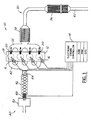
- FIG. 1 shows a diagram of an internal combustion engine 10 using a system for minimizing fuel evaporative emissions in accordance with the present invention.
- the engine 10 shown in FIG. 1 is a gasoline four-stroke direct fuel injection (DFI) internal combustion engine having a plurality of cylinders, each of the cylinders having a combustion chamber 18 and corresponding fuel injectors 16 and spark plugs 20.
- the engine 10, however, can be any internal combustion engine, such as a port fuel injection (PFI) or diesel engine, having an air induction system provided on the intake side of the engine as shown in FIG. 1.
- DFI direct fuel injection
- PFI port fuel injection
- diesel engine having an air induction system provided on the intake side of the engine as shown in FIG. 1.
- the air induction system 40 includes an intake manifold 42, a throttle valve 44 and corresponding assembly, a fuel vapor storage duct 46 and an air mass flow (MAF) sensor 48 integrated with an air cleaner assembly 50.
- Exhaust gases generated during combustion are provided to an exhaust system 30, which nominally includes an exhaust manifold 32, an upstream three-way catalytic converter 34, a downstream nitrogen oxide (NO X ) trap 36 and a tailpipe 42.
- NO X nitrogen oxide
- an electronic engine controller 14 Connected to the MAF sensor is an electronic engine controller 14 having a processor (CPU) with corresponding input/output ports, read-only memory (ROM) or any suitable electronic storage medium containing processor-executable instructions and calibration values, random-access memory (RAM) and a data bus of any suitable configuration.
- the controller 14 receives signals from a variety of sensors coupled to the engine 10 and/or the vehicle and controls the operation of the fuel injectors 16, each of which is positioned to inject fuel into their respective cylinders 18 in precise quantities as determined by the controller 14.
- the controller 14 similarly controls the operation of each of the spark plugs 20 in a known manner.
- the controller 14 also controls the operation of the throttle valve 44 , which in turn regulates the mass flow of air into the engine 10.
- the air mass flow sensor 48 positioned upstream of the duct 46, provides a signal representing the air mass flow resulting from positioning of the engine's throttle 44.
- the air mass flow signal from the sensor 48 is utilized by the controller 14 to calculate an air mass value indicative of a mass of air flowing per unit time into the engine's induction system 40.
- FIG. 2 shows a flow diagram of a preferred method of the present invention for minimizing fuel evaporative emissions of an internal combustion engine.
- the method which is directed at reducing the amount of hydrocarbon molecules migrating from the combustion chambers (or fuel ports) past the throttle valve assembly, includes the steps of absorbing, upstream of the throttle valve assembly, fuel vapors emitted from the engine through the intake manifold and throttle valve assembly, step 210, releasing the stored fuel vapors for use by the engine, step 220 and optionally adjusting or "calibrating out” an amount of fuel to be injected into the combustion chambers to take into account the released fuel vapors, step 230.
- the vapor absorbing step, step 210 is performed by the duct 46, which is preferably a plastic cylinder disposed between the MAF sensor 46 and the throttle valve 44.
- the interior of the duct 46 is lined with activated carbon particles or the like for absorbing hydrocarbon molecules or the like contained in the fuel vapor emissions.
- the release or purging of the hydrocarbon molecules, step 220 is nominally performed during engine start-up or selected periods of engine operation.
- the engine controller 14 which normally determines an amount of fuel to be provided to the engine, adjusts the amount based on the volume of stored fuel vapors released from the duct 46.
- FIGS. 3 and 4 show cross-sectional views of preferred embodiments of the duct apparatus shown above in FIG. 1.
- the duct includes a plastic tube 310, an adhesive layer 312 disposed on the interior surface of the tube 310, and a coating of activated carbon particles 314 disposed on the adhesive layer 312.
- the coating 314 is applied using a suitable spray deposition technique.
- a layer 416 of activated carbon particles combined with a gas-permeable polymer such as polyethylene is disposed along the interior of the plastic duct 310 to provided improved absorption of hydrocarbon molecules.
Landscapes
- Engineering & Computer Science (AREA)
- Chemical & Material Sciences (AREA)
- Combustion & Propulsion (AREA)
- Mechanical Engineering (AREA)
- General Engineering & Computer Science (AREA)
- Dispersion Chemistry (AREA)
- Physics & Mathematics (AREA)
- Fluid Mechanics (AREA)
- Analytical Chemistry (AREA)
- Ceramic Engineering (AREA)
- Supplying Secondary Fuel Or The Like To Fuel, Air Or Fuel-Air Mixtures (AREA)
Abstract
Description
- The present invention relates generally to fuel vapor emission control in vehicles having internal combustion engines. More particularly, the invention relates to a system and method for removing hydrocarbons from the air induction system of an internal combustion engine.
- Vehicles having internal combustion engines are known to release unwanted hydrocarbons during refueling and cold starting of the vehicle engine. During refueling, for example, unburned fuel vapors containing such hydrocarbons are released from the vehicle's fuel tank after the fuel tank cap is removed. Similarly, because a stoichiometric air/fuel ratio is difficult to achieve during cold start, a higher proportion of unburned fuel vapor is delivered to the vehicle's catalytic converter thus resulting in higher concentration of hydrocarbons released into the atmosphere.
- As such, vehicles have been designed to include various systems and methods for minimizing the release of fuel vapor emissions during vehicle start-up and refueling. Examples of such systems are disclosed in United States Patent Nos. RE 36,737, 5,924,410 and 5,957,114, which are all assigned to the assignee of the present invention.
- Such systems, are not helpful for controlling the release of unburned fuel vapors from combustion chambers and/or fuel ports during engine operation. One such situation occurs after evaporative emissions migrate or "leak" back in an "upstream" direction from the combustion chambers and/or fuel ports of the engine through a corresponding intake manifold and throttle valve. Any emissions migrating back through the intake valves are then subject to release into the atmosphere.
- Accordingly, and further in light of increasingly stringent environmental standards, there is a need to minimize the amount of unburned fuel vapors migrating back into the air induction system of an internal combustion engine.
- The above-described limitations and inadequacies of conventional fuel evaporative emission controls systems and methods are substantially overcome by the present invention, in which a method is provided for minimizing evaporative fuel emissions of a vehicle having an internal combustion engine. The method includes the step of storing fuel vapors emanating from the engine to prevent the migration of the fuel vapors in an "upstream" direction from the engine through the throttle valve assembly. Preferably, the stored fuel vapors are released back into the engine's air induction system during engine operation. During engine start-up, for example, the amount of fuel required for start-up can be adjusted in order to take into account the release of the fuel vapors into the air induction system of the engine.
- An advantage of the above method is that the amount of fuel evaporative vapors accumulated in the engine's air induction system is reduced, thereby preventing the release of residual gases, e.g. , hydrocarbons, into the atmosphere. By storing and then releasing the evaporative emissions at an appropriate time, such a system is especially advantageous for compliance with government fuel emissions standards. The amount of stored fuel vapor released back into the engine's air induction system can then be used to "calibrate-out" a corresponding amount of fuel required for engine operation. For example, taking into account the amount of released fuel vapors can reduce the amount of fuel required for engine start-up. Consequently, an additional advantage is realized in that less fuel is required for engine start-up.
- In accordance with a related aspect of the present invention, a corresponding system for minimizing fuel evaporative emissions is provided. The system includes a duct connected to a throttle valve assembly for providing atmospheric air to the engine and a fuel vapor absorbing material disposed on the interior of the duct for absorbing and storingthe fuel emissions emanating from the engine through the intakemanifold and the throttle valve assembly. Preferably, the duct is includes a first end coupled to the throttle valve assembly, and a fuel vapor absorbing material disposed on the interior for absorbing and storing the fuel emissions. The system also includes an engine controller for determining an amount of fuel to be provided to the engine and adjusting an amount of fuel provided to the engine after the stored fuel emissions are released from the material.
- Still further, in accordance with yet another aspect of the present invention, an article of manufacture is disclosed for operating an internal combustion engine having a throttle valve assembly in cooperation with a corresponding intake manifold and fuel vapor absorbing material near the throttle valve assembly for absorbing and storing evaporative fuel emissions emanating from the engine through the intake manifold and the throttle valve assembly. The article of manufacture includes a computer usable medium and a computer readable program code embodied in the computer usable medium for directing the computer to perform the steps of directing the computer to perform the step steps of determining an amount of fuel to be provided to the engine and adjusting an amount of fuel provided to the engine after the stored evaporative fuel emissions are released from the material.
- Further objects, features and advantages of the invention will become apparent from the following detailed description taken in conjunction with the accompanying figures showing illustrative embodiments of the invention.
- The invention will now be described further, by way of example, with reference to the accompanying drawings, in which:
- FIG. 1 is a diagram of an internal combustion engine using a system for minimizing fuel evaporative emissions in accordance with a preferred embodiment of the present invention;
- FIG. 2 is a flow diagram of a preferred method of the present invention for minimizing fuel evaporative emissions of an internal combustion engine;
- FIG. 3 is cross-sectional view of a preferred embodiment of an apparatus for minimizing fuel evaporative emissions of an internal combustion engine; and
- FIG. 4 is cross-sectional view of another preferred embodiment of an apparatus for minimizing fuel evaporative emissions of an internal combustion engine.
-
- FIG. 1 shows a diagram of an
internal combustion engine 10 using a system for minimizing fuel evaporative emissions in accordance with the present invention. Theengine 10 shown in FIG. 1, by way of example and not limitation, is a gasoline four-stroke direct fuel injection (DFI) internal combustion engine having a plurality of cylinders, each of the cylinders having acombustion chamber 18 andcorresponding fuel injectors 16 andspark plugs 20. Theengine 10, however, can be any internal combustion engine, such as a port fuel injection (PFI) or diesel engine, having an air induction system provided on the intake side of the engine as shown in FIG. 1. Theair induction system 40 includes anintake manifold 42, athrottle valve 44 and corresponding assembly, a fuelvapor storage duct 46 and an air mass flow (MAF)sensor 48 integrated with anair cleaner assembly 50. Exhaust gases generated during combustion are provided to anexhaust system 30, which nominally includes anexhaust manifold 32, an upstream three-waycatalytic converter 34, a downstream nitrogen oxide (NOX)trap 36 and atailpipe 42. - Connected to the MAF sensor is an
electronic engine controller 14 having a processor (CPU) with corresponding input/output ports, read-only memory (ROM) or any suitable electronic storage medium containing processor-executable instructions and calibration values, random-access memory (RAM) and a data bus of any suitable configuration. Thecontroller 14 receives signals from a variety of sensors coupled to theengine 10 and/or the vehicle and controls the operation of thefuel injectors 16, each of which is positioned to inject fuel into theirrespective cylinders 18 in precise quantities as determined by thecontroller 14. Thecontroller 14 similarly controls the operation of each of thespark plugs 20 in a known manner. - The
controller 14 also controls the operation of thethrottle valve 44 , which in turn regulates the mass flow of air into theengine 10. The airmass flow sensor 48, positioned upstream of theduct 46, provides a signal representing the air mass flow resulting from positioning of the engine'sthrottle 44. The air mass flow signal from thesensor 48 is utilized by thecontroller 14 to calculate an air mass value indicative of a mass of air flowing per unit time into the engine'sinduction system 40. - FIG. 2 shows a flow diagram of a preferred method of the present invention for minimizing fuel evaporative emissions of an internal combustion engine. The method, which is directed at reducing the amount of hydrocarbon molecules migrating from the combustion chambers (or fuel ports) past the throttle valve assembly, includes the steps of absorbing, upstream of the throttle valve assembly, fuel vapors emitted from the engine through the intake manifold and throttle valve assembly,
step 210, releasing the stored fuel vapors for use by the engine,step 220 and optionally adjusting or "calibrating out" an amount of fuel to be injected into the combustion chambers to take into account the released fuel vapors,step 230. The vapor absorbing step,step 210, is performed by theduct 46, which is preferably a plastic cylinder disposed between theMAF sensor 46 and thethrottle valve 44. The interior of theduct 46 is lined with activated carbon particles or the like for absorbing hydrocarbon molecules or the like contained in the fuel vapor emissions. The release or purging of the hydrocarbon molecules,step 220, is nominally performed during engine start-up or selected periods of engine operation. Preferably, theengine controller 14 , which normally determines an amount of fuel to be provided to the engine, adjusts the amount based on the volume of stored fuel vapors released from theduct 46. - FIGS. 3 and 4 show cross-sectional views of preferred embodiments of the duct apparatus shown above in FIG. 1. In a first embodiment, as shown in FIG. 3, the duct includes a
plastic tube 310, anadhesive layer 312 disposed on the interior surface of thetube 310, and a coating of activatedcarbon particles 314 disposed on theadhesive layer 312. Preferably, thecoating 314 is applied using a suitable spray deposition technique. Alternatively, as shown in FIG. 4, alayer 416 of activated carbon particles combined with a gas-permeable polymer such as polyethylene is disposed along the interior of theplastic duct 310 to provided improved absorption of hydrocarbon molecules.
Claims (11)
- A method for minimizing evaporative fuel emissions of a vehicle having an internal combustion engine(10), the engine having a combustion chamber(18), a corresponding fuel(16) injector and a throttle valve assembly(44) in cooperation with a corresponding intake manifold(42), the method comprising the step of storing fuel vapors that emanate from the engine(10) to prevent migration thereof from the engine through the throttle valve assembly(44).
- A method as claimed in claim 1, further comprising the step of releasing the stored fuel vapors into the engine(10) to prevent the escape thereof into the atmosphere.
- A method as claimed in claim 2, further comprising the step of adjusting an amount of fuel provided to the engine(10) after the stored fuel vapors are released.
- A method as claimed in claim 3, wherein said releasing step is performed prior to engine start-up, said method further comprising the step of using the adjusted amount of fuel during engine start-up.
- A system for minimizing evaporative fuel emissions of a vehicle having an internal combustion engine(10), the engine having a combustion chamber(18), a corresponding fuel injector(16) and a throttle valve assembly(44) in cooperation with a corresponding intake manifold(42), said system comprising:a duct(310) connected to the throttle valve assembly(44) for providing atmospheric air to the engine; anda fuel vapor absorbing material(314) disposed on the interior of the duct(310) for absorbing and storing fuel vapors emitted from the engine(10) and through the throttle valve assembly(44).
- A system as claimed in claim 5, further comprising an engine controller(14) for determining an amount of fuel to be provided to the engine(10) and adjusting an amount of fuel provided to the engine after the stored fuel vapors are released from said material(314).
- An apparatus coupled to the air induction system of an internal combustion engine(10), the air induction system having an intake manifold(42) and a throttle valve assembly(44), the apparatus comprising:a duct(310) having a first end coupled to the throttle valve assembly(44); anda fuel vapor absorbing material(314) disposed on the interior of said duct(310) for absorbing and storing the evaporative fuel emissions.
- An apparatus as claimed in claim 7, wherein:said duct(310) comprises a plastic tube;said fuel vapor absorbing material comprising a layer(314) of activated carbon particles, said apparatus further comprising an adhesive layer(312) disposed between the interior of said plastic tube(310) and said activated carbon layer (314).
- An apparatus as claimed in claim 8, wherein said fuel vapor absorbing material comprises a layer(416) of activated carbon particles mixed with a gas-permeable polymer.
- An apparatus as claimed in claim 9, wherein said gas-permeable polymer is polyethylene.
- An article of manufacture for operating an internal combustion engine having a throttle valve assembly(44) in cooperation with a corresponding intake manifold(42) and fuel vapor absorbing material(314) near the throttle valve assembly(44) for absorbing and storing evaporative fuel emissions emanating from the engine and through the throttle valve assembly(44), comprising:a computer readable medium; anda computer readable program embodied in the computer readable medium for directing the computer to perform the step steps of determining an amount of fuel to be provided to the engine(10) and adjusting an amount of fuel provided to the engine after the stored evaporative fuel emissions are released from the material(314).
Applications Claiming Priority (2)
| Application Number | Priority Date | Filing Date | Title |
|---|---|---|---|
| US666195 | 2000-09-21 | ||
| US09/666,195 US6438486B1 (en) | 2000-09-21 | 2000-09-21 | System and method for minimizing fuel evaporative emissions from an internal combustion engine |
Publications (3)
| Publication Number | Publication Date |
|---|---|
| EP1191217A2 true EP1191217A2 (en) | 2002-03-27 |
| EP1191217A3 EP1191217A3 (en) | 2003-01-08 |
| EP1191217B1 EP1191217B1 (en) | 2009-04-22 |
Family
ID=24673214
Family Applications (1)
| Application Number | Title | Priority Date | Filing Date |
|---|---|---|---|
| EP01000396A Expired - Lifetime EP1191217B1 (en) | 2000-09-21 | 2001-08-22 | System and method for minimizing fuel evaporative emissions from an internal combustion engine |
Country Status (3)
| Country | Link |
|---|---|
| US (1) | US6438486B1 (en) |
| EP (1) | EP1191217B1 (en) |
| DE (1) | DE60138442D1 (en) |
Cited By (4)
| Publication number | Priority date | Publication date | Assignee | Title |
|---|---|---|---|---|
| WO2004033889A1 (en) * | 2002-10-08 | 2004-04-22 | Meadwestvaco Corporation | Carbon-containing shaped cylinders for engine air induction system emission reduction |
| EP1945329A2 (en) * | 2005-10-11 | 2008-07-23 | Multisorb Technologies, Inc. | Hydrocarbon emission scavenger |
| EP2135996A1 (en) * | 2008-06-19 | 2009-12-23 | MAHLE International GmbH | Carbon-enriched material |
| EP2990636A1 (en) * | 2014-08-26 | 2016-03-02 | Westaflex Tubos Flexiveis Ltda. | Anti-pollution porous flex pipe |
Families Citing this family (13)
| Publication number | Priority date | Publication date | Assignee | Title |
|---|---|---|---|---|
| US6679228B1 (en) * | 1999-08-16 | 2004-01-20 | Delphi Technologies, Inc. | Low evaporative emissions integrated air fuel module |
| US6817345B2 (en) * | 2002-12-19 | 2004-11-16 | Ford Global Technologies, Llc | Carbon Impregnation of porous ducting for evaporative emissions absorption |
| US7377966B2 (en) * | 2004-08-26 | 2008-05-27 | Honeywell International, Inc. | Adsorptive assembly and method of making the same |
| US7182802B2 (en) * | 2003-03-19 | 2007-02-27 | Honeywell International, Inc. | Evaporative emissions filter |
| US7344586B2 (en) * | 2003-03-19 | 2008-03-18 | Honeywell International, Inc. | Evaporative emissions filter |
| US7422628B2 (en) * | 2003-05-12 | 2008-09-09 | Basf Catalysts Llc | Volatile hydrocarbon adsorber unit |
| US7070641B1 (en) * | 2003-12-03 | 2006-07-04 | Fleetguard, Inc. | Carbon media filter element |
| DE602004007394T2 (en) * | 2004-10-26 | 2008-03-06 | Ford Global Technologies, LLC, Dearborn | Injection valve leakage current limit |
| US7531029B2 (en) * | 2005-06-01 | 2009-05-12 | Basf Catalysts Llc | Coated screen adsorption unit for controlling evaporative hydrocarbon emissions |
| US7578285B2 (en) * | 2005-11-17 | 2009-08-25 | Basf Catalysts Llc | Hydrocarbon adsorption filter for air intake system evaporative emission control |
| US7976619B2 (en) * | 2007-11-09 | 2011-07-12 | Mann & Hummel Gmbh | Hydrocarbon adsorber with purge airflow channel |
| US8191535B2 (en) * | 2008-10-10 | 2012-06-05 | Ford Global Technologies, Llc | Sleeve hydrocarbon trap |
| US8372477B2 (en) * | 2009-06-11 | 2013-02-12 | Basf Corporation | Polymeric trap with adsorbent |
Citations (3)
| Publication number | Priority date | Publication date | Assignee | Title |
|---|---|---|---|---|
| US36410A (en) | 1862-09-09 | Hose-coupling | ||
| US5924410A (en) | 1998-07-20 | 1999-07-20 | Ford Motor Company | Evaporative emission canister for an automotive vehicle |
| US5957114A (en) | 1998-07-17 | 1999-09-28 | Ford Motor Company | Evaporative emission canister for an automotive vehicle |
Family Cites Families (7)
| Publication number | Priority date | Publication date | Assignee | Title |
|---|---|---|---|---|
| US3747303A (en) * | 1971-06-01 | 1973-07-24 | Gen Motors Corp | Air-filter and carbon-bed element for an air cleaner assembly |
| JPS5933890Y2 (en) * | 1978-03-07 | 1984-09-20 | 株式会社デンソー | Air cleaner element for internal combustion engine |
| JPS5746031A (en) * | 1980-09-01 | 1982-03-16 | Toyota Motor Corp | Method of controlling supplied quantity of fuel to internal combustion engine |
| JPS5872669A (en) * | 1981-10-27 | 1983-04-30 | Tokyo Roki Kk | Air-cleaner for internal-combustion engine |
| US4715340A (en) | 1987-05-04 | 1987-12-29 | Ford Motor Company | Reduction of HC emissions for vapor recovery purge systems |
| US5482023A (en) * | 1994-12-27 | 1996-01-09 | Hitachi America, Ltd., Research And Development Division | Cold start fuel control system |
| JP3856252B2 (en) * | 1997-07-15 | 2006-12-13 | 本田技研工業株式会社 | Fuel supply control device for internal combustion engine |
-
2000
- 2000-09-21 US US09/666,195 patent/US6438486B1/en not_active Expired - Lifetime
-
2001
- 2001-08-22 DE DE60138442T patent/DE60138442D1/en not_active Expired - Lifetime
- 2001-08-22 EP EP01000396A patent/EP1191217B1/en not_active Expired - Lifetime
Patent Citations (3)
| Publication number | Priority date | Publication date | Assignee | Title |
|---|---|---|---|---|
| US36410A (en) | 1862-09-09 | Hose-coupling | ||
| US5957114A (en) | 1998-07-17 | 1999-09-28 | Ford Motor Company | Evaporative emission canister for an automotive vehicle |
| US5924410A (en) | 1998-07-20 | 1999-07-20 | Ford Motor Company | Evaporative emission canister for an automotive vehicle |
Cited By (7)
| Publication number | Priority date | Publication date | Assignee | Title |
|---|---|---|---|---|
| WO2004033889A1 (en) * | 2002-10-08 | 2004-04-22 | Meadwestvaco Corporation | Carbon-containing shaped cylinders for engine air induction system emission reduction |
| EP1945329A2 (en) * | 2005-10-11 | 2008-07-23 | Multisorb Technologies, Inc. | Hydrocarbon emission scavenger |
| EP1945329A4 (en) * | 2005-10-11 | 2012-05-23 | Multisorb Tech Inc | Hydrocarbon emission scavenger |
| US8475569B2 (en) | 2005-10-11 | 2013-07-02 | Multisorb Technologies, Inc. | Hydrocarbon emission scavenger and method for making |
| EP2135996A1 (en) * | 2008-06-19 | 2009-12-23 | MAHLE International GmbH | Carbon-enriched material |
| DE102008029079A1 (en) * | 2008-06-19 | 2009-12-24 | Mahle International Gmbh | Carbon enriched material |
| EP2990636A1 (en) * | 2014-08-26 | 2016-03-02 | Westaflex Tubos Flexiveis Ltda. | Anti-pollution porous flex pipe |
Also Published As
| Publication number | Publication date |
|---|---|
| US6438486B1 (en) | 2002-08-20 |
| DE60138442D1 (en) | 2009-06-04 |
| EP1191217B1 (en) | 2009-04-22 |
| EP1191217A3 (en) | 2003-01-08 |
Similar Documents
| Publication | Publication Date | Title |
|---|---|---|
| US6438486B1 (en) | System and method for minimizing fuel evaporative emissions from an internal combustion engine | |
| US6227177B1 (en) | Apparatus for controlling internal combustion engine equipped with evaporative emission control system | |
| US6196203B1 (en) | Evaporative emission control system with reduced running losses | |
| US5080078A (en) | Fuel vapor recovery control system | |
| JP4166779B2 (en) | Internal combustion engine control device | |
| US6990963B2 (en) | System and method for vaporized fuel processing | |
| JPH0524938U (en) | Fuel vapor emission suppression device for internal combustion engine | |
| US6374811B1 (en) | System and method for minimizing fuel evaporative emissions from an internal combustion engine | |
| US6729312B2 (en) | Fuel vapor treatment apparatus | |
| KR100306186B1 (en) | Gasoline vapor purging system of interal combustion engine | |
| US5609142A (en) | Fuel-vapor treatment method and apparatus for internal combustion engine | |
| GB2220086A (en) | Air-fuel ratio control system for automotive engines | |
| US5680756A (en) | Fuel-vapor treatment method and apparatus for internal combustion engine | |
| JPH05223017A (en) | In-cylinder injection type internal combustion engine | |
| JP2889419B2 (en) | Air-fuel ratio learning control method | |
| JP7472764B2 (en) | Engine equipment | |
| JP2021131032A (en) | Controller of internal combustion engine | |
| JP3555394B2 (en) | Air-fuel ratio control device for internal combustion engine | |
| GB2303668A (en) | Engine vapour canister purge system | |
| US6273063B1 (en) | Apparatus and method for controlling idle rotation speed of an internal combustion engine | |
| JP3065176B2 (en) | Engine air-fuel ratio control device | |
| JP2889420B2 (en) | Air-fuel ratio control method | |
| JP3384291B2 (en) | Evaporative fuel treatment system for internal combustion engine | |
| KR19980036338A (en) | Canister Fuzzy Control System and its Control Method | |
| JP2023090018A (en) | Internal combustion engine control device |
Legal Events
| Date | Code | Title | Description |
|---|---|---|---|
| PUAI | Public reference made under article 153(3) epc to a published international application that has entered the european phase |
Free format text: ORIGINAL CODE: 0009012 |
|
| AK | Designated contracting states |
Kind code of ref document: A2 Designated state(s): AT BE CH CY DE DK ES FI FR GB GR IE IT LI LU MC NL PT SE TR |
|
| AX | Request for extension of the european patent |
Free format text: AL;LT;LV;MK;RO;SI |
|
| PUAL | Search report despatched |
Free format text: ORIGINAL CODE: 0009013 |
|
| AK | Designated contracting states |
Kind code of ref document: A3 Designated state(s): AT BE CH CY DE DK ES FI FR GB GR IE IT LI LU MC NL PT SE TR |
|
| AX | Request for extension of the european patent |
Free format text: AL;LT;LV;MK;RO;SI |
|
| 17P | Request for examination filed |
Effective date: 20030613 |
|
| AKX | Designation fees paid |
Designated state(s): DE GB SE |
|
| 17Q | First examination report despatched |
Effective date: 20061114 |
|
| 17Q | First examination report despatched |
Effective date: 20061114 |
|
| GRAP | Despatch of communication of intention to grant a patent |
Free format text: ORIGINAL CODE: EPIDOSNIGR1 |
|
| GRAS | Grant fee paid |
Free format text: ORIGINAL CODE: EPIDOSNIGR3 |
|
| GRAA | (expected) grant |
Free format text: ORIGINAL CODE: 0009210 |
|
| AK | Designated contracting states |
Kind code of ref document: B1 Designated state(s): DE GB SE |
|
| REG | Reference to a national code |
Ref country code: GB Ref legal event code: FG4D |
|
| REF | Corresponds to: |
Ref document number: 60138442 Country of ref document: DE Date of ref document: 20090604 Kind code of ref document: P |
|
| PG25 | Lapsed in a contracting state [announced via postgrant information from national office to epo] |
Ref country code: SE Free format text: LAPSE BECAUSE OF FAILURE TO SUBMIT A TRANSLATION OF THE DESCRIPTION OR TO PAY THE FEE WITHIN THE PRESCRIBED TIME-LIMIT Effective date: 20090722 |
|
| PGFP | Annual fee paid to national office [announced via postgrant information from national office to epo] |
Ref country code: GB Payment date: 20090708 Year of fee payment: 9 |
|
| PLBE | No opposition filed within time limit |
Free format text: ORIGINAL CODE: 0009261 |
|
| STAA | Information on the status of an ep patent application or granted ep patent |
Free format text: STATUS: NO OPPOSITION FILED WITHIN TIME LIMIT |
|
| 26N | No opposition filed |
Effective date: 20100125 |
|
| GBPC | Gb: european patent ceased through non-payment of renewal fee |
Effective date: 20100822 |
|
| PG25 | Lapsed in a contracting state [announced via postgrant information from national office to epo] |
Ref country code: GB Free format text: LAPSE BECAUSE OF NON-PAYMENT OF DUE FEES Effective date: 20100822 |
|
| REG | Reference to a national code |
Ref country code: DE Ref legal event code: R082 Ref document number: 60138442 Country of ref document: DE Representative=s name: DOERFLER, THOMAS, DR.-ING., DE |
|
| PGFP | Annual fee paid to national office [announced via postgrant information from national office to epo] |
Ref country code: DE Payment date: 20200713 Year of fee payment: 20 |
|
| REG | Reference to a national code |
Ref country code: DE Ref legal event code: R071 Ref document number: 60138442 Country of ref document: DE |