EP1190855A1 - Printing quality inspection apparatus - Google Patents
Printing quality inspection apparatus Download PDFInfo
- Publication number
- EP1190855A1 EP1190855A1 EP01121779A EP01121779A EP1190855A1 EP 1190855 A1 EP1190855 A1 EP 1190855A1 EP 01121779 A EP01121779 A EP 01121779A EP 01121779 A EP01121779 A EP 01121779A EP 1190855 A1 EP1190855 A1 EP 1190855A1
- Authority
- EP
- European Patent Office
- Prior art keywords
- printing quality
- moving
- inspection apparatus
- inspection
- correcting
- Prior art date
- Legal status (The legal status is an assumption and is not a legal conclusion. Google has not performed a legal analysis and makes no representation as to the accuracy of the status listed.)
- Granted
Links
Images


Classifications
-
- B—PERFORMING OPERATIONS; TRANSPORTING
- B41—PRINTING; LINING MACHINES; TYPEWRITERS; STAMPS
- B41F—PRINTING MACHINES OR PRESSES
- B41F33/00—Indicating, counting, warning, control or safety devices
- B41F33/0036—Devices for scanning or checking the printed matter for quality control
Definitions
- the present invention relates to a printing quality inspection apparatus of printed sheet-like object, particularly effective when applied in inspection of printing quality of printed sheet-like object.
- an inspection device is installed for inspecting the printing quality of printed sheet-like object.
- This inspection device is designed to suck a printed sheet, in the midst of transfer of the sheet to a delivery table by means of a delivery chain after being printed in the printing unit, onto a suction table, spread the sheet uniformly, take an image of the printed surface of the printed sheet by a CCD camera or other image taking device, compare signal from the camera and the predetermined quality standard by means of a control device, and discharge the sheet onto the delivery table while sorting between sheet-like object satisfying the quality standard and sheet-like object not satisfying the quality standard (for example, Japanese Laid-open Patent No. 5-254091).
- the printing quality inspection apparatus is directed to a printing quality inspection apparatus characterized by comprising the correcting means for correcting the position of the printed sheet-like object, and inspection means disposed inside of a frame for inspecting the printing quality of sheet-like object corrected of position. by the correcting means in which moving means is provided to move at least either one of the correcting means and the inspection means to a maintenance position for maintaining.
- the printing quality inspection apparatus relates to the printing quality inspection apparatus of the first aspect characterized in that the moving means is inspection moving means for moving the inspection means between the working position for inspecting the printing quality of printed sheet-like object and the maintenance position.
- the printing quality inspection apparatus relates to the printing quality inspection apparatus of the second aspect characterized in that the working position is inside the frame and the maintenance position is outside the frame.
- the printing quality inspection apparatus relates to the printing quality inspection apparatus of the second aspect characterized in that the inspection moving means includes a rotatably provided support roller, and a guide for guiding between said working position and the maintenance position of the inspection means.
- the printing quality inspection apparatus relates to the printing quality inspection apparatus of the fourth aspect characterized in that the support roller is rotatably disposed at an inspection means side, and the guide is a support rail for supporting the support roller, and connecting between the working position and the maintenance position of the inspection means.
- the printing quality inspection apparatus relates to the printing quality inspection apparatus of the fifth aspect characterized in that the support rail includes a first support rail provided inside of the frame for supporting said support roller, and a second support rail movably provided to be positioned on an extension of said first support rail.
- the printing quality inspection apparatus relates to the printing quality inspection apparatus of the sixth aspect characterized in that the second support rail is swing pivotally provided so as to move between a guide position positioned on the extension of the first rail and a retreat position for retreating from the guide position.
- the printing quality inspection apparatus relates to the printing quality inspection apparatus of any one of the fifth aspect to seventh aspect characterized by comprising a restricting rail for restricting movement of the support roller in a direction orthogonal to the running direction of the support roller.
- the printing quality inspection apparatus relates to the printing quality inspection apparatus of any one of the fifth aspect to seventh aspect characterized by comprising inspection positioning fixing means for positioning and fixing the inspection means such that the inspection means may be positioned at the working position.
- the printing quality inspection apparatus relates to the printing quality inspection apparatus of the first aspect characterized in that the moving means is corrector moving means for moving the correcting means between the working position for inspecting the position of printed sheet-like object and the maintenance position.
- the printing quality inspection apparatus relates to the printing quality inspection apparatus of the tenth aspect characterized in that the corrector moving means includes a roller provided at the correcting means side, and a guide provided inside of the frame for guiding the moving of the correcting means.
- the printing quality inspection apparatus relates to the printing quality inspection apparatus of the eleventh aspect characterized by comprising a support roller provided at one of the frame side and the correcting means side, and rotatable along the moving direction of the correcting means, and a support rail provided at the other of the frame side and the correcting means side, the support rail being engaged with the support roller for restricting a movement of the correcting means in a direction orthogonal to the moving direction of the correcting means.
- the printing quality inspection apparatus relates to the printing quality inspection apparatus of the eleventh aspect or twelfth aspect characterized by comprising corrector positioning fixing means for positioning and fixing the correcting means such that the correcting means may be positioned at the working position.
- the printing quality inspection apparatus relates to the printing quality inspection apparatus of the first aspect characterized in that said maintenance position includes a inspection means maintenance position for maintaining the inspection means, and a correcting means maintenance position for maintaining the correcting means, and the moving means includes corrector moving means for moving the correcting means between the correcting position for correcting the position of printed sheet-like object and the correcting means maintenance position, and inspection moving means for moving the inspection means between the inspecting position for inspecting the printing quality of printed sheet-like object and the inspection means maintenance position.
- the printing quality inspection apparatus relates to the printing quality inspection apparatus of the fourteenth aspect characterized in that a moving direction of the inspection means by the inspection moving means and the moving direction of the correcting means by the corrector moving means are different.
- FIG. 1 is a general structural diagram of an intaglio printing press
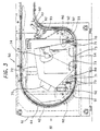
- Fig. 2 is a schematic structural diagram of suction table section of inspection unit
- Fig. 3 is a schematic structural diagram of imaging section of the inspection unit in Fig. 2
- Fig. 4 is a view from arrow IV direction in Fig. 3
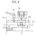
- Fig. 5 is a magnified view of a fixing tool in Fig. 4.
- a feeder board 21 is coupled to a sheet feeder 10 for feeding each sheet from a stack of sheet-like object 100.
- a swing device 22 for transferring a sheet 100 to a gripper, not shown, provided in a transfer cylinder 23.
- This transfer cylinder 23 is opposite to a transfer cylinder 24 having a gripper not shown, and this transfer cylinder 23 transfers the sheet 100 held in the gripper to the gripper of the transfer cylinder 24.
- the transfer cylinder 24 is opposite to an impression cylinder 31 of triple cylinder of a printing unit 30, and the sheet 100 held by the gripper is transferred to a gripper, not shown, of the impression cylinder 31.
- an intaglio cylinder 32 of triple cylinder is in contact with the cylinder 31.
- a plurality of Chablon rollers 33 which are ink feed cylinders, are disposed at specific intervals along the peripheral direction of the intaglio cylinder 32 and in contact with the cylinder 32.
- Ink feeders 34 are in contact with these Chablon rollers 33.
- a pre-wiping device 35 is in contact with the cylinder 32.
- a wiping roller 36 is in contact with the cylinder 32.
- the lower side of the wiping roller 36 is immersed in a wiping tank 37 filled with a wiping solution.
- a delivery cylinder 41 is in contact with the cylinder 31.
- a chain 42 provided with a plurality of grippers 43 at specific intervals for receiving the sheet-like object 100 from the gripper of the impression cylinder 31 is wound around the delivery cylinder 41.
- This chain 42 runs and moves along a chain guide 44 as shown in Fig. 2 and Fig. 3, and this chain guide 44 guides running of the chain 42 so that the sheet 100 received in the gripper 43 from the impression cylinder 31 passes near an air duct 46, passes through an inspection unit 40 which is the printing quality inspection apparatus of the invention, and then moves onto a delivery table 45 of a delivery unit 40.
- a moving table 52 beneath the inside of a unit frame 51 of the inspection unit 50, there is a moving table 52 provided with casters 53 which are rolls that rolls along the running direction of the chain 42 in the lower part.
- a suction table 54 As shown in Fig. 2, beneath the inside of a unit frame 51 of the inspection unit 50, there is a moving table 52 provided with casters 53 which are rolls that rolls along the running direction of the chain 42 in the lower part.
- a suction table 54 as a box-shaped correcting means provided with multiple pores on the top, and this suction table 54 is coupled to a suction pump 55 disposed on the top of the unit frame 51 by means of a hose 56.
- a tubular suction roller 57 having multiple pores on the outer circumference thereof is rotatably provided.
- a pulley 57a is rotatably provided coaxially on the suction roller 57 integrally, and an endless belt 59, applied on a pulley 58a of a drive motor 58 provided on the moving table 52, is applied thereon.
- the suction roller 57 is coupled to a suction pump 61 disposed on the top of the unit frame 51 by means of a hose not shown.
- reference numeral 60 is a tension roller for adjusting the tension of the endless belt 59.
- a handle 62 is attached to the moving table 52, and by gripping the handle 62 and moving the moving table 52 along the running direction of the chain 42, the moving table 52 can be moved between a working position (solid line position in Fig. 2) inside the unit frame 51, and a maintenance position (double dot chain line position in Fig. 2) outside the unit frame 51.
- a plurality of support rollers 63 rotatable along the moving direction of the suction table 54 are disposed at specific intervals.
- concave support rails 64 are provided for restricting the suction table 54 in the direction orthogonal to the moving direction of the suction table 54, as being engaged with the support rollers 63.
- the support rails 64 are, in order to support the moving table 52 through the support rollers 63 when the moving table 52 comes to the working position, defined in configuration such that the length between the floor and the lower surface of support rail 64 at the maintenance position side of the moving table 52 may be nearly the same as the length between the lower side of the outer circumference of the support rollers 63 and the lower side of the outer circumference of the casters 53, and that the length between the floor and the lower surface of the support rail 64 at the working position portion for supporting the support rollers 63 may be slightly larger than the length between the lower side of the outer circumference of the support rollers 63 and the lower side of the outer circumference of the casters 53.
- guide rollers 65 which are a plurality of guide members for guiding the move of the moving table 52 while contacting with the sides of the moving table 52.
- the unit frame 51 further incorporates a stopper 66 for positioning and stopping the move of the moving table 52 so as to position the suction table 54 at the working position, and a lock device 67 for positioning and fixing the moving table 52 so as to position and fix the suction table 54 at the working position.
- reference numeral 68 is a limit switch.
- corrector moving means is composed of the casters 53, guide rollers 65, and others, while the corrector positioning fixing means is composed of the stopper 66, lock device 67, and others.
- a pair of first support rails 70 having the longitudinal direction extended in the horizontal direction orthogonal to the running direction of the chain 42, are provided to bridge over the unit frame 51.
- a shroud 72 Above the first support rails 70, a shroud 72, opened downward, is supported through support roller 71.
- handles 73 are attached, and by gripping the handles 73, the shroud 72 can be moved along the first support rails 70.
- a camera 74 such as CCD camera, and a light 75 are provided above the inside of the shroud 72.
- the inspection means is composed of the camera 74, light 75, and others.
- the base end sides of a pair of second support rails 76 are coupled so as to be rotatable about the axis with the axial direction in the horizontal direction orthogonal to the longitudinal direction of the first support rails 70.
- the base end of a bar-shaped stand 77 is coupled so as to be rotatable in the same direction as the rotating direction of the base end sides of the second support rails 76.
- stopper plates 78 are provided for fixing and holding the second support rails 76 in a state of positioning the leading end sides of the second support rails 76 upward.
- stopper plates 79 are provided for fixing and holding the stand 77 in upright position on the second support rails 76.
- the support rails which are guides, are composed of the first support rails 70, second support rails 76, and others, while the inspection moving means is composed of the support rails, support rollers 71, stand 77, stopper plates 78, 79, and others.
- restricting rails 80 are provided for restricting the movement of the support rollers 71 in a direction orthogonal to the running direction of the support rollers 71 without confining the rotation of the support rollers 71.
- a fixing tool 81 is provided as inspection means positioning and fixing means for positioning and fixing the shroud 72 on the restricting rails 80, so that the camera 74 and light 75 may be positioned on the working position inside the unit frame 51.
- a fixing block 82 is provided for coupling the fixing tool 81 for fixing the shroud 72 so that the camera 74 and light 75 may be positioned at the maintenance position on the second support rails 76 outside of the unit frame 51.
- reference numeral 91 is a suction device
- 92 is a blowing fan
- 93 is a draft tube
- 94 is a blowing pump.
- the sheet 100 is transferred to the transfer cylinder 23 by means of a swing device 22, and is further transferred to the impression cylinder 31 through the transfer cylinder 24.
- the ink is supplied to the intaglio cylinder 32 through Chablon cylinders 33a to 33c from the ink feeders 34a to 34c, the ink is deprived of extra portion by the pre-wiping device 35 and wiping roller 37, and is transferred to the sheet 100 held on the impression cylinder 31.
- the printed sheet 100 is transferred from the impression cylinder 31 to the delivery cylinder 41, and is gripped by the gripper 43, and is delivered into the inspection unit 50 as the chain 42 is driven along the guide chain 44.
- the position of the sheet 100 running and moving in the inspection unit 50 is adjusted by the suction device 91 and blowing fan 92, and after the moving speed is decelerated by the suction roller 57, it is sucked by the suction table 54 to be corrected of its position, and runs and moves on the table 54.
- the camera 74 takes the image of the printing surface of the sheet 100, and a control device, not shown, compares the signal from the camera 74, and a predetermined quality standard, and judges the printing quality of the sheet 100.
- the sheet 100 leaves the suction table 54, and further runs and moves, and is discharged onto the delivery table 45 for approved sheet-like object if judged to satisfy the quality standard, or discharged onto the delivery table 45 for rejected sheet-like object if judged not to satisfy the quality standard.
- the inspection unit 50 is cleaned and checked as follows.
- the lock device 67 attached to the unit frame 51, is unlocked, and the handle 62 is pulled. Then, the moving table 52 is moved from the working position inside of the unit frame 51 to the outside of the unit frame 51 as being guided by the guide roller 65 and others, the support roller 63 departs from the support rail 64, and the suction table 54 and suction roller 57 are drawn out to the maintenance position outside of the unit frame 51.
- the suction table 54 and others are moved to a position free from obstacles, so that the maintenance of the suction table 54 and others can be done in a natural position.
- the moving table 52 After finishing the maintenance of the suction table 54 and others, and when the handle 62 is pushed, the moving table 52 is guided by the guide roller 65 and others and is moved from the maintenance position outside the unit frame 51 to the inside the unit frame 51.
- the support roller 63 is mounted on the support rail 64, the moving table 52 is pushed in until abutting against the stopper 66, and then by locking the moving table 52 by the lock device 67, the suction table 54 and others are positioned and fixed at the working position inside of the unit frame 51.
- the moving table 52 is supported on the unit frame 51 through the support roller 63 and support rail 64.
- the suction table 54 is positioned and fixed securely at the specified working position, so that the printing quality of the sheet 100 can be inspected precisely by the camera 74.
- the stopper plate 78 of the second support rail 76 is canceled, the second support rail 76 is tilted, the stand 77 is set upright, to hold the stopper plate 79 in upright position, and then the second support rail 76 is extended to the maintenance position outside of the unit frame 51.
- the fixing tool 81 of the shroud 72 is cleared, the handle 73 is pulled, the shroud 72 is moved along the firsts support rail 70 through the support roller 71 to be mounted on the second support rail 76, and is moved to the leading end side of the second support rail 76.
- the fixing tool 81 on the fixing block 82 the shroud 72 can be pulled out from the working position inside the unit frame 51 to the maintenance position outside the unit frame 51, and is fixed and held.
- the maintenance of the camera 74 and light 75 in the shroud 72 can be done in a natural and comfortable position.
- the fixing tool 81 is detached from the fixing block 82, and the handle 73 is pushed. Then, the shroud 72 is moved along the second support rail 76 through the support roller 71, is mounted on the first support rail 70, and returned to the working position inside of the unit frame 51. Thereafter the fixing tool 81 is fixed on the restricting rail 80, the stopper plate 79 of the stand 77 is cleared to tilt the stand 77, the second support rail 76 is erected along the unit frame 51, and this state is held by the stopper plate 78, so that the camera 74 and light 75 in the shroud 72 can be returned from the maintenance position outside of the unit frame 51 to the working position inside of the unit frame 51, positioned and fixed.
- the camera 74 and light 75 in the shroud 72 can be securely positioned and fixed at the specified working position.
- the printing quality of the sheet 100 can be inspected precisely by the camera 74 and light 75.
- the working position is quite natural during maintenance, and the working efficiency can be enhanced.
- the correcting means such as the suction table 54
- the inspection means such as the camera 74 or light 75
- the correcting means can be moved in different directions, maintenance of the correcting means and maintenance of the inspection means can be done at the same time, and the working time can be shortened.
- the support rollers 63 are provided in the moving table 54, and the support rails 64 are provided in the unit frame 51, but the same effects, as in the embodiment, are obtained if, for example, the support rails are provided in the moving table (suction table side) and the support rollers are provided in the unit frame.
- the moving table 52 and shroud 72 are moved in different directions, but maintenance may be also done easily if the moving table 52 and the shroud 72 are moved in the same direction.
- the moving table 52 and shroud 72 are moved manually, but the moving table 52 and shroud 72 may be also moved automatically by using a motor or other actuator.
- the second support rail 76 is provided such that it swings pivotally so that the second support rail 76 may be positioned on the extension of the first support rail 70.
- the second support rail 76 may be provided slidably so that the second support rail 76 may be positioned on the extension of the first support rail 70.
- the embodiment is applied to the intaglio printing press, but the invention may be also applied in other printing presses such as offset printing press, or being installed independently without being incorporated in the printing press. It may be also realized as a printing quality inspection apparatus for inspecting the printing quality of sheet-like object printed by a printing press.
- the inspection means and correcting means can be moved between the working position and the maintenance position, at the time of maintenance, only by moving the inspection means and correcting means to a proper maintenance position, maintenance can be done in a natural position, so that the working efficiency may be enhanced.
Landscapes
- Engineering & Computer Science (AREA)
- Quality & Reliability (AREA)
- Inking, Control Or Cleaning Of Printing Machines (AREA)
- Investigating Materials By The Use Of Optical Means Adapted For Particular Applications (AREA)
- Printing Methods (AREA)
- Supply, Installation And Extraction Of Printed Sheets Or Plates (AREA)
- Dot-Matrix Printers And Others (AREA)
- Paper (AREA)
- Steering Control In Accordance With Driving Conditions (AREA)
Abstract
Description
- The entire disclosure of Japanese Patent Application No.2000-288795 filed on September 22nd, 2000 including specification, claims, drawings, and summary is incorporated herein by reference in its entirety.
- The present invention relates to a printing quality inspection apparatus of printed sheet-like object, particularly effective when applied in inspection of printing quality of printed sheet-like object.
- Between a printing unit and a delivery unit of a printing press, an inspection device is installed for inspecting the printing quality of printed sheet-like object. This inspection device is designed to suck a printed sheet, in the midst of transfer of the sheet to a delivery table by means of a delivery chain after being printed in the printing unit, onto a suction table, spread the sheet uniformly, take an image of the printed surface of the printed sheet by a CCD camera or other image taking device, compare signal from the camera and the predetermined quality standard by means of a control device, and discharge the sheet onto the delivery table while sorting between sheet-like object satisfying the quality standard and sheet-like object not satisfying the quality standard (for example, Japanese Laid-open Patent No. 5-254091).
- As the printing quality is inspected in this manner, paper dust of sheet-like object and mist of printing ink are collected on the suction holes of the suction table and/or the lens of the camera, and it becomes gradually difficult to continue inspection, and therefore cleaning of the suction table and camera is required in every specific operating time. However, since the suction table and camera are assembled inside of the main body frame, the working position is difficult for maintenance, and the working efficiency is lowered.
- It is hence an object of the invention to present a printing quality inspection apparatus featuring ease of maintenance.
- To solve the above problems, the printing quality inspection apparatus according to the first aspect of the invention is directed to a printing quality inspection apparatus characterized by comprising the correcting means for correcting the position of the printed sheet-like object, and inspection means disposed inside of a frame for inspecting the printing quality of sheet-like object corrected of position. by the correcting means in which moving means is provided to move at least either one of the correcting means and the inspection means to a maintenance position for maintaining.
- The printing quality inspection apparatus according to the second aspect of the invention relates to the printing quality inspection apparatus of the first aspect characterized in that the moving means is inspection moving means for moving the inspection means between the working position for inspecting the printing quality of printed sheet-like object and the maintenance position.
- The printing quality inspection apparatus according to the third aspect of the invention relates to the printing quality inspection apparatus of the second aspect characterized in that the working position is inside the frame and the maintenance position is outside the frame.
- The printing quality inspection apparatus according to the fourth aspect of the invention relates to the printing quality inspection apparatus of the second aspect characterized in that the inspection moving means includes a rotatably provided support roller, and a guide for guiding between said working position and the maintenance position of the inspection means.
- The printing quality inspection apparatus according to the fifth aspect of the invention relates to the printing quality inspection apparatus of the fourth aspect characterized in that the support roller is rotatably disposed at an inspection means side, and the guide is a support rail for supporting the support roller, and connecting between the working position and the maintenance position of the inspection means.
- The printing quality inspection apparatus according to a sixth aspect of the invention relates to the printing quality inspection apparatus of the fifth aspect characterized in that the support rail includes a first support rail provided inside of the frame for supporting said support roller, and a second support rail movably provided to be positioned on an extension of said first support rail.
- The printing quality inspection apparatus according to a seventh aspect of the invention relates to the printing quality inspection apparatus of the sixth aspect characterized in that the second support rail is swing pivotally provided so as to move between a guide position positioned on the extension of the first rail and a retreat position for retreating from the guide position.
- The printing quality inspection apparatus according to an eighth aspect of the invention relates to the printing quality inspection apparatus of any one of the fifth aspect to seventh aspect characterized by comprising a restricting rail for restricting movement of the support roller in a direction orthogonal to the running direction of the support roller.
- The printing quality inspection apparatus according to a ninth aspect of the invention relates to the printing quality inspection apparatus of any one of the fifth aspect to seventh aspect characterized by comprising inspection positioning fixing means for positioning and fixing the inspection means such that the inspection means may be positioned at the working position.
- The printing quality inspection apparatus according to a tenth aspect of the invention relates to the printing quality inspection apparatus of the first aspect characterized in that the moving means is corrector moving means for moving the correcting means between the working position for inspecting the position of printed sheet-like object and the maintenance position.
- The printing quality inspection apparatus according to an eleventh aspect of the invention relates to the printing quality inspection apparatus of the tenth aspect characterized in that the corrector moving means includes a roller provided at the correcting means side, and a guide provided inside of the frame for guiding the moving of the correcting means.
- The printing quality inspection apparatus according to a twelfth aspect of the invention relates to the printing quality inspection apparatus of the eleventh aspect characterized by comprising a support roller provided at one of the frame side and the correcting means side, and rotatable along the moving direction of the correcting means, and a support rail provided at the other of the frame side and the correcting means side, the support rail being engaged with the support roller for restricting a movement of the correcting means in a direction orthogonal to the moving direction of the correcting means.
- The printing quality inspection apparatus according to a thirteenth aspect of the invention relates to the printing quality inspection apparatus of the eleventh aspect or twelfth aspect characterized by comprising corrector positioning fixing means for positioning and fixing the correcting means such that the correcting means may be positioned at the working position.
- The printing quality inspection apparatus according to a fourteenth aspect of the invention relates to the printing quality inspection apparatus of the first aspect characterized in that said maintenance position includes a inspection means maintenance position for maintaining the inspection means, and a correcting means maintenance position for maintaining the correcting means, and the moving means includes corrector moving means for moving the correcting means between the correcting position for correcting the position of printed sheet-like object and the correcting means maintenance position, and inspection moving means for moving the inspection means between the inspecting position for inspecting the printing quality of printed sheet-like object and the inspection means maintenance position.
- The printing quality inspection apparatus according to a fifteenth aspect of the invention relates to the printing quality inspection apparatus of the fourteenth aspect characterized in that a moving direction of the inspection means by the inspection moving means and the moving direction of the correcting means by the corrector moving means are different.
- The present invention will become more fully understood from the detailed description given hereinbelow and the accompanying drawings which are given by way of illustration only, and thus are not limitative of the present invention, and wherein:
- Fig. 1 is a general structural diagram of a printing quality inspection machine assembled in an intaglio printing press according to an embodiment of the invention;
- Fig. 2 is a schematic structural diagram of suction table section of inspection unit in Fig. 1;
- Fig. 3 is a schematic structural diagram of imaging section of the inspection unit in Fig. 2;
- Fig. 4 is a view from arrow IV direction in Fig. 3; and
- Fig. 5 is a magnified view of a fixing tool in Fig. 4.
-
- A preferred embodiment of a printing quality inspection apparatus of the invention assembled in an intaglio printing press is explained by referring to Fig. 1 to Fig. 5. Fig. 1 is a general structural diagram of an intaglio printing press, Fig. 2 is a schematic structural diagram of suction table section of inspection unit, Fig. 3 is a schematic structural diagram of imaging section of the inspection unit in Fig. 2, Fig. 4 is a view from arrow IV direction in Fig. 3, and Fig. 5 is a magnified view of a fixing tool in Fig. 4.
- As shown in Fig. 1, the base end side of a
feeder board 21 is coupled to asheet feeder 10 for feeding each sheet from a stack of sheet-like object 100. At the leading end side of thefeeder board 21, there is aswing device 22 for transferring asheet 100 to a gripper, not shown, provided in atransfer cylinder 23. Thistransfer cylinder 23 is opposite to atransfer cylinder 24 having a gripper not shown, and thistransfer cylinder 23 transfers thesheet 100 held in the gripper to the gripper of thetransfer cylinder 24. - The
transfer cylinder 24 is opposite to animpression cylinder 31 of triple cylinder of aprinting unit 30, and thesheet 100 held by the gripper is transferred to a gripper, not shown, of theimpression cylinder 31. At the downstream side in rotating direction from thetransfer cylinder 24 of theimpression cylinder 31, anintaglio cylinder 32 of triple cylinder is in contact with thecylinder 31. At the downstream side in rotating direction from theimpression cylinder 31 of theintaglio cylinder 32, a plurality of Chablon rollers 33, which are ink feed cylinders, are disposed at specific intervals along the peripheral direction of theintaglio cylinder 32 and in contact with thecylinder 32. Ink feeders 34 are in contact with these Chablon rollers 33. - At the downstream side in rotating direction from the Chablon rollers 33 of the
intaglio cylinder 32, apre-wiping device 35 is in contact with thecylinder 32. At the downstream side in rotating direction from thepre-wiping device 35 of theintaglio cylinder 32, awiping roller 36 is in contact with thecylinder 32. The lower side of thewiping roller 36 is immersed in awiping tank 37 filled with a wiping solution. - At the downstream side in rotating direction from the
intaglio cylinder 32 of theimpression cylinder 31, adelivery cylinder 41 is in contact with thecylinder 31. Achain 42 provided with a plurality ofgrippers 43 at specific intervals for receiving the sheet-like object 100 from the gripper of theimpression cylinder 31 is wound around thedelivery cylinder 41. Thischain 42 runs and moves along achain guide 44 as shown in Fig. 2 and Fig. 3, and thischain guide 44 guides running of thechain 42 so that thesheet 100 received in thegripper 43 from theimpression cylinder 31 passes near anair duct 46, passes through aninspection unit 40 which is the printing quality inspection apparatus of the invention, and then moves onto a delivery table 45 of adelivery unit 40. - As shown in Fig. 2, beneath the inside of a
unit frame 51 of theinspection unit 50, there is a moving table 52 provided withcasters 53 which are rolls that rolls along the running direction of thechain 42 in the lower part. In the upper part of the moving table 42, there is a suction table 54 as a box-shaped correcting means provided with multiple pores on the top, and this suction table 54 is coupled to asuction pump 55 disposed on the top of theunit frame 51 by means of ahose 56. - Near the upstream side end in running direction of the
chain 42 of the suction table 54 on the moving table 52, atubular suction roller 57, having multiple pores on the outer circumference thereof is rotatably provided. A pulley 57a is rotatably provided coaxially on thesuction roller 57 integrally, and anendless belt 59, applied on apulley 58a of adrive motor 58 provided on the moving table 52, is applied thereon. Thesuction roller 57 is coupled to asuction pump 61 disposed on the top of theunit frame 51 by means of a hose not shown. In Fig. 2, reference numeral 60 is a tension roller for adjusting the tension of theendless belt 59. - A
handle 62 is attached to the moving table 52, and by gripping thehandle 62 and moving the moving table 52 along the running direction of thechain 42, the moving table 52 can be moved between a working position (solid line position in Fig. 2) inside theunit frame 51, and a maintenance position (double dot chain line position in Fig. 2) outside theunit frame 51. - At both sides in the horizontal direction orthogonal to the moving direction of the moving table 52, a plurality of
support rollers 63 rotatable along the moving direction of the suction table 54 are disposed at specific intervals. At both walls in the horizontal direction orthogonal to the moving direction of the moving table 52 of the working position of the moving table 52 in theunit frame 51,concave support rails 64 are provided for restricting the suction table 54 in the direction orthogonal to the moving direction of the suction table 54, as being engaged with thesupport rollers 63. - The
support rails 64 are, in order to support the moving table 52 through thesupport rollers 63 when the moving table 52 comes to the working position, defined in configuration such that the length between the floor and the lower surface ofsupport rail 64 at the maintenance position side of the moving table 52 may be nearly the same as the length between the lower side of the outer circumference of thesupport rollers 63 and the lower side of the outer circumference of thecasters 53, and that the length between the floor and the lower surface of thesupport rail 64 at the working position portion for supporting thesupport rollers 63 may be slightly larger than the length between the lower side of the outer circumference of thesupport rollers 63 and the lower side of the outer circumference of thecasters 53. - At both walls in the horizontal direction orthogonal to the moving direction of the moving table 52 in the
unit frame 51, there areguide rollers 65, which are a plurality of guide members for guiding the move of the moving table 52 while contacting with the sides of the moving table 52. Theunit frame 51 further incorporates a stopper 66 for positioning and stopping the move of the moving table 52 so as to position the suction table 54 at the working position, and alock device 67 for positioning and fixing the moving table 52 so as to position and fix the suction table 54 at the working position. In Fig. 2,reference numeral 68 is a limit switch. - In this embodiment, corrector moving means is composed of the
casters 53,guide rollers 65, and others, while the corrector positioning fixing means is composed of the stopper 66,lock device 67, and others. - On the other hand, as shown in Fig. 3 and Fig. 4, above the working position of the suction table 54 in the
unit frame 51, a pair offirst support rails 70, having the longitudinal direction extended in the horizontal direction orthogonal to the running direction of thechain 42, are provided to bridge over theunit frame 51. Above thefirst support rails 70, ashroud 72, opened downward, is supported throughsupport roller 71. At both end sides in the longitudinal direction of the first support rails 70 of theshroud 72, handles 73 are attached, and by gripping thehandles 73, theshroud 72 can be moved along the first support rails 70. Above the inside of theshroud 72, acamera 74, such as CCD camera, and a light 75 are provided. In the embodiment, the inspection means is composed of thecamera 74, light 75, and others. - As shown in Fig. 4, in the portion of the position on an extension of the
outside support rail 70 at one side of theunit frame 51, the base end sides of a pair of second support rails 76 are coupled so as to be rotatable about the axis with the axial direction in the horizontal direction orthogonal to the longitudinal direction of the first support rails 70. At the leading end sides of the second support rails 76, the base end of a bar-shapedstand 77 is coupled so as to be rotatable in the same direction as the rotating direction of the base end sides of the second support rails 76. At the base end sides of the second support rails 76,stopper plates 78 are provided for fixing and holding the second support rails 76 in a state of positioning the leading end sides of the second support rails 76 upward. At the leading end sides of the second support rails 76,stopper plates 79 are provided for fixing and holding thestand 77 in upright position on the second support rails 76. - In this embodiment, thus, the support rails, which are guides, are composed of the first support rails 70, second support rails 76, and others, while the inspection moving means is composed of the support rails,
support rollers 71, stand 77,stopper plates - At both end sides in the longitudinal direction of the first support rails 70, restricting
rails 80 are provided for restricting the movement of thesupport rollers 71 in a direction orthogonal to the running direction of thesupport rollers 71 without confining the rotation of thesupport rollers 71. As shown in Fig. 4 and Fig. 5, at thesecond support rail 76 side of theshroud 72. a fixingtool 81 is provided as inspection means positioning and fixing means for positioning and fixing theshroud 72 on the restrictingrails 80, so that thecamera 74 and light 75 may be positioned on the working position inside theunit frame 51. At the leading end sides of the second support rails 76, a fixingblock 82 is provided for coupling the fixingtool 81 for fixing theshroud 72 so that thecamera 74 and light 75 may be positioned at the maintenance position on the second support rails 76 outside of theunit frame 51. - In Fig. 2 and Fig. 3,
reference numeral 91 is a suction device, 92 is a blowing fan, 93 is a draft tube, and 94 is a blowing pump. - In the intaglio printing press having such configuration, when a
sheet 100 is supplied on thefeeder board 21 from thepaper feeder 10, thesheet 100 is transferred to thetransfer cylinder 23 by means of aswing device 22, and is further transferred to theimpression cylinder 31 through thetransfer cylinder 24. On the other hand, when the ink is supplied to theintaglio cylinder 32 through Chablon cylinders 33a to 33c from the ink feeders 34a to 34c, the ink is deprived of extra portion by thepre-wiping device 35 and wipingroller 37, and is transferred to thesheet 100 held on theimpression cylinder 31. The printedsheet 100 is transferred from theimpression cylinder 31 to thedelivery cylinder 41, and is gripped by thegripper 43, and is delivered into theinspection unit 50 as thechain 42 is driven along theguide chain 44. - The position of the
sheet 100 running and moving in theinspection unit 50 is adjusted by thesuction device 91 and blowingfan 92, and after the moving speed is decelerated by thesuction roller 57, it is sucked by the suction table 54 to be corrected of its position, and runs and moves on the table 54. At this time, thecamera 74 takes the image of the printing surface of thesheet 100, and a control device, not shown, compares the signal from thecamera 74, and a predetermined quality standard, and judges the printing quality of thesheet 100. Thus, after inspection of printing quality, thesheet 100 leaves the suction table 54, and further runs and moves, and is discharged onto the delivery table 45 for approved sheet-like object if judged to satisfy the quality standard, or discharged onto the delivery table 45 for rejected sheet-like object if judged not to satisfy the quality standard. - After operating the printing press for a specific time, aside from the maintenance of the
printing unit 30 and others, theinspection unit 50 is cleaned and checked as follows. - First, for maintaining the suction table 54, the
lock device 67, attached to theunit frame 51, is unlocked, and thehandle 62 is pulled. Then, the moving table 52 is moved from the working position inside of theunit frame 51 to the outside of theunit frame 51 as being guided by theguide roller 65 and others, thesupport roller 63 departs from thesupport rail 64, and the suction table 54 andsuction roller 57 are drawn out to the maintenance position outside of theunit frame 51. - As a result, the suction table 54 and others are moved to a position free from obstacles, so that the maintenance of the suction table 54 and others can be done in a natural position.
- After finishing the maintenance of the suction table 54 and others, and when the
handle 62 is pushed, the moving table 52 is guided by theguide roller 65 and others and is moved from the maintenance position outside theunit frame 51 to the inside theunit frame 51. Thesupport roller 63 is mounted on thesupport rail 64, the moving table 52 is pushed in until abutting against the stopper 66, and then by locking the moving table 52 by thelock device 67, the suction table 54 and others are positioned and fixed at the working position inside of theunit frame 51. - At this time, as explained above, since the length between the floor and the lower surface of the
support rail 64 for supporting thesupport roller 63 is set slightly larger than the length between the lower side of the outer circumference of thesupport roller 63 and the lower side of the outer circumference of thecaster 53, the moving table 52 is supported on theunit frame 51 through thesupport roller 63 andsupport rail 64. - Accordingly, the suction table 54 is positioned and fixed securely at the specified working position, so that the printing quality of the
sheet 100 can be inspected precisely by thecamera 74. - Next, in the case of maintenance of the
camera 74 and light 75, thestopper plate 78 of thesecond support rail 76 is canceled, thesecond support rail 76 is tilted, thestand 77 is set upright, to hold thestopper plate 79 in upright position, and then thesecond support rail 76 is extended to the maintenance position outside of theunit frame 51. Thereoften, the fixingtool 81 of theshroud 72 is cleared, thehandle 73 is pulled, theshroud 72 is moved along the firsts supportrail 70 through thesupport roller 71 to be mounted on thesecond support rail 76, and is moved to the leading end side of thesecond support rail 76. By fixing the fixingtool 81 on the fixingblock 82. theshroud 72 can be pulled out from the working position inside theunit frame 51 to the maintenance position outside theunit frame 51, and is fixed and held. - As a result, being moved to a position free from obstacles around the
shroud 72, the maintenance of thecamera 74 and light 75 in theshroud 72 can be done in a natural and comfortable position. - After the maintenance of the
camera 74 and light 75, the fixingtool 81 is detached from the fixingblock 82, and thehandle 73 is pushed. Then, theshroud 72 is moved along thesecond support rail 76 through thesupport roller 71, is mounted on thefirst support rail 70, and returned to the working position inside of theunit frame 51. Thereafter the fixingtool 81 is fixed on the restrictingrail 80, thestopper plate 79 of thestand 77 is cleared to tilt thestand 77, thesecond support rail 76 is erected along theunit frame 51, and this state is held by thestopper plate 78, so that thecamera 74 and light 75 in theshroud 72 can be returned from the maintenance position outside of theunit frame 51 to the working position inside of theunit frame 51, positioned and fixed. - At this time, since the movement of the
support roller 71, in a direction orthogonal to the running direction, is defined by the restrictingrail 80, thecamera 74 and light 75 in theshroud 72 can be securely positioned and fixed at the specified working position. Thus, the printing quality of thesheet 100 can be inspected precisely by thecamera 74 andlight 75. - Thus, in this
inspection unit 50, the working position is quite natural during maintenance, and the working efficiency can be enhanced. Moreover, since the correcting means, such as the suction table 54, and the inspection means, such as thecamera 74 or light 75, can be moved in different directions, maintenance of the correcting means and maintenance of the inspection means can be done at the same time, and the working time can be shortened. - In this embodiment, the
support rollers 63 are provided in the moving table 54, and the support rails 64 are provided in theunit frame 51, but the same effects, as in the embodiment, are obtained if, for example, the support rails are provided in the moving table (suction table side) and the support rollers are provided in the unit frame. - In the embodiment, the moving table 52 and
shroud 72 are moved in different directions, but maintenance may be also done easily if the moving table 52 and theshroud 72 are moved in the same direction. - In the embodiment, the moving table 52 and
shroud 72 are moved manually, but the moving table 52 andshroud 72 may be also moved automatically by using a motor or other actuator. Further, in the embodiment, thesecond support rail 76 is provided such that it swings pivotally so that thesecond support rail 76 may be positioned on the extension of thefirst support rail 70. However, for example, thesecond support rail 76 may be provided slidably so that thesecond support rail 76 may be positioned on the extension of thefirst support rail 70. - The embodiment is applied to the intaglio printing press, but the invention may be also applied in other printing presses such as offset printing press, or being installed independently without being incorporated in the printing press. It may be also realized as a printing quality inspection apparatus for inspecting the printing quality of sheet-like object printed by a printing press.
- According to the printing quality inspection apparatus of the invention, since the inspection means and correcting means can be moved between the working position and the maintenance position, at the time of maintenance, only by moving the inspection means and correcting means to a proper maintenance position, maintenance can be done in a natural position, so that the working efficiency may be enhanced.
- The invention being thus described, it will be obvious that the same may be varied in many ways. Such variations are not to be regarded as a departure from the sprit and scope of the invention, and all such modifications as would be obvious to one skilled in the art are intended to be included within the scope of the following claims.
Claims (15)
- A printing quality inspection apparatus characterized by comprising :correcting means (54) for inspecting the position of printed sheet-like object (100);inspection means (74,75) disposed inside a frame (51) for inspecting a printing quality of the sheet-like object (100) corrected of position by said correcting means (54); andmoving means for moving at least one of said correcting means (54) and said inspection means (74, 75) to a maintenance position for maintenance.
- The printing quality inspection apparatus of claim 1, characterized in that said moving means is inspection moving means (70,71,76-79) for moving said inspection means (74,75) between the working position for inspecting the printing quality of printed sheet-like object (100) and the maintenance position.
- The printing quality inspection apparatus of claim 2, characterized in that said working position is inside said frame (51) and said maintenance position is outside the frame (51).
- The printing quality inspection apparatus of claim 2, characterized in that said inspection moving means (70,71,76-79) includes a rotatably provided support roller (71), and a guide (70,76) for guiding between said working position and said maintenance position of said inspection means (74,76).
- The printing quality inspection apparatus of claim 4, characterized in that said support roller (71) is rotatably disposed at an inspection means (74,75) side, and said guide (70,76) is a support rail (70,76) for supporting said support roller (71), and connecting between said working position and said maintenance position of said inspection means (74,75).
- The printing quality inspection apparatus of claim 5, characterized in that said support rail (70,76) includes a first support rail (70) provided inside said frame (51) for supporting said support roller (71), and a second support rail (76) movably provided to be positioned on an extension of said first support rail (70).
- The printing quality inspection apparatus of claim 6. characterized in that said second support rail (76) is swing pivotally provided so as to move between a guide position positioned on the extension of said first rail (70) and a retreat position for retreating from said guide position.
- The printing quality inspection apparatus of any one of claims 5 to 7, characterized by comprising:a restricting rail (80) for restricting movement of said support roller (71) in a direction orthogonal to the running direction of said support roller (71).
- The printing quality inspection apparatus of any one of claims 5 to 7, characterized by comprising:inspection positioning fixing means (81) for positioning and fixing said inspection means (74,75) such that said inspection means (74,75) may be positioned at said working position.
- The printing quality inspection apparatus of claim 1, characterized in that said moving means is corrector moving means (53,65) for moving said correcting means (54) between said working position for correcting the position of printed sheet-like object (100) and said maintenance position.
- The printing quality inspection apparatus of claim 10, characterized in that said corrector moving means (53,65) includes a roller (53) provided at said correcting means (54) side, and a guide (65) provided inside of said frame (51) for guiding the moving of said correcting means (54).
- The printing quality inspection apparatus of claim 11, characterized by comprising :a support roller (63) provided at one of said frame (51) side and said correcting means (54) side, and rotatable along the moving direction of said correcting means (54); anda support rail (64) provided at the other of said frame (51) side and said correcting means (54) side, said support rail (64) being engaged with said support roller (63) for restricting a movement of said correcting means (54) in a direction orthogonal to the moving direction of said correcting means (54).
- The printing quality inspection apparatus of claim 11 or 12, characterized by comprising:corrector positioning fixing means (66,67) for positioning and fixing said correcting means (54) such that said correcting means (54) may be positioned at said working position.
- The printing quality inspection apparatus of claim 1, characterized in that said maintenance position includes a inspection means maintenance position for maintaining said inspection means (74,75), and a correcting means maintenance position for maintaining said correcting means (54), and said moving means includes corrector moving means (53, 65) for moving said correcting means (54) between the correcting position for correcting the position of printed sheet-like object (100) and said correcting means maintenance position, and inspection moving means (70,71,76-79) for moving said inspection means (74,75) between the inspecting position for inspecting the printing quality of printed sheet-like object (100) and said inspection means maintenance position.
- The printing quality inspection apparatus of claim 14, characterized in that a moving direction of said inspection means (74,75) by said inspection moving means (70, 71, 76-79) and the moving direction of said correcting means (54) by said corrector moving means (53,65) are different.
Priority Applications (1)
| Application Number | Priority Date | Filing Date | Title |
|---|---|---|---|
| DE60133443.4T DE60133443T3 (en) | 2000-09-22 | 2001-09-20 | Print quality control device |
Applications Claiming Priority (2)
| Application Number | Priority Date | Filing Date | Title |
|---|---|---|---|
| JP2000288795A JP4616451B2 (en) | 2000-09-22 | 2000-09-22 | Print quality inspection device |
| JP2000288795 | 2000-09-22 |
Publications (3)
| Publication Number | Publication Date |
|---|---|
| EP1190855A1 true EP1190855A1 (en) | 2002-03-27 |
| EP1190855B1 EP1190855B1 (en) | 2008-04-02 |
| EP1190855B2 EP1190855B2 (en) | 2017-11-08 |
Family
ID=18772318
Family Applications (1)
| Application Number | Title | Priority Date | Filing Date |
|---|---|---|---|
| EP01121779.1A Expired - Lifetime EP1190855B2 (en) | 2000-09-22 | 2001-09-20 | Printing quality inspection apparatus |
Country Status (6)
| Country | Link |
|---|---|
| US (1) | US6772689B2 (en) |
| EP (1) | EP1190855B2 (en) |
| JP (1) | JP4616451B2 (en) |
| AT (1) | ATE391018T1 (en) |
| DE (1) | DE60133443T3 (en) |
| ES (1) | ES2300293T3 (en) |
Cited By (16)
| Publication number | Priority date | Publication date | Assignee | Title |
|---|---|---|---|---|
| US6685368B1 (en) * | 2002-10-28 | 2004-02-03 | Hewlett-Packard Development Company, L.P. | Printing system having output sampling feature |
| EP1454746A1 (en) | 2003-03-06 | 2004-09-08 | MAN Roland Druckmaschinen AG | Image inspection system for a printing press |
| DE102005037497A1 (en) * | 2005-08-09 | 2007-02-15 | Man Roland Druckmaschinen Ag | Method for individually characterizing each copy on a printed sheet comprises applying a printing ink or coating on the sheet using a printing device connected to a laser device with a thermosensitive ink |
| DE102005037498A1 (en) * | 2005-08-09 | 2007-02-15 | Man Roland Druckmaschinen Ag | Quality control system for a printing press |
| DE102005054122A1 (en) * | 2005-11-12 | 2007-05-16 | Roland Man Druckmasch | Quality control system for a printing press |
| EP1790473A1 (en) | 2005-11-25 | 2007-05-30 | Kba-Giori S.A. | Method for detection of occurrence of printing errors on printed substrates during processing thereof on a printing press |
| EP1834781A2 (en) | 2006-03-17 | 2007-09-19 | MAN Roland Druckmaschinen AG | Sheet fed printing press with a post-processing unit |
| DE102006012513A1 (en) * | 2006-03-18 | 2007-09-20 | Man Roland Druckmaschinen Ag | Image processing system for a printing press |
| US8047089B2 (en) | 2006-11-20 | 2011-11-01 | Heidelberger Druckmachinen Ag | Device for the optical measurement of a printed sheet and method for operating the device |
| EP2383213A1 (en) | 2008-06-27 | 2011-11-02 | Kba-Notasys Sa | Inspection system for inspecting the quality of printed sheets |
| EP2394817A1 (en) * | 2010-06-11 | 2011-12-14 | Goss International Montataire SA | Method for treating flat products and corresponding device |
| US20130104758A1 (en) * | 2011-10-26 | 2013-05-02 | Komori Corporation | Intaglio printing press |
| US8613254B2 (en) | 2005-11-25 | 2013-12-24 | Kba-Notasys Sa | Method for detection of occurrence of printing errors on printed substrates during processing thereof on a printing press |
| DE102016213111A1 (en) | 2016-07-19 | 2018-01-25 | Koenig & Bauer Ag | Inspection system with multiple detection areas |
| DE102007051582B4 (en) | 2006-11-20 | 2018-03-08 | Heidelberger Druckmaschinen Ag | Method for operating a device for optically measuring a printed sheet |
| EP3715127A1 (en) | 2019-03-26 | 2020-09-30 | Inopaq Technologies Sàrl | Printed sheet inspection system and sheet-fed printing press comprising the same |
Families Citing this family (10)
| Publication number | Priority date | Publication date | Assignee | Title |
|---|---|---|---|---|
| JP4317087B2 (en) * | 2004-07-08 | 2009-08-19 | 株式会社小森コーポレーション | Sheet material discharge device |
| DE102005026127B4 (en) * | 2005-06-07 | 2007-02-08 | Koenig & Bauer Ag | Printing machine and a method for producing a printed product |
| DE102005060441A1 (en) * | 2005-12-17 | 2007-06-21 | Man Roland Druckmaschinen Ag | Sheetfed |
| EP1834779A1 (en) * | 2006-03-14 | 2007-09-19 | Kba-Giori S.A. | Inspection system for a sheet-fed recto-verso printing press |
| DE102006015828A1 (en) * | 2006-04-03 | 2007-10-04 | Man Roland Druckmaschinen Ag | Image inspection system for e.g. sheet-fed offset press, has sorting device, where data, which are stored in memory and obtained by image processing algorithm, are stored in another memory for analysis by algorithm |
| EP1995062A1 (en) * | 2007-05-25 | 2008-11-26 | Kba-Giori S.A. | Intaglio printing press systems for recto-verso intaglio-printing of sheets, in particular for the production of banknotes and the like securities |
| CN101850652B (en) * | 2009-03-19 | 2015-03-11 | 小森公司 | Quality inspection apparatus for sheet-shaped matter |
| JP5286158B2 (en) * | 2009-05-26 | 2013-09-11 | 三菱重工印刷紙工機械株式会社 | Printer |
| EP2399745A1 (en) | 2010-06-25 | 2011-12-28 | KBA-NotaSys SA | Inspection system for in-line inspection of printed material produced on an intaglio printing press |
| KR102263829B1 (en) | 2019-10-23 | 2021-06-10 | 이재권 | Multistage opening and closing type awning |
Citations (3)
| Publication number | Priority date | Publication date | Assignee | Title |
|---|---|---|---|---|
| WO1994008791A1 (en) * | 1992-10-16 | 1994-04-28 | Insinööritoimisto Data OY | Apparatus for the quality control of a print produced by a printing machine |
| US5329852A (en) * | 1991-08-14 | 1994-07-19 | Koenig & Bauer Aktiengesellschaft | Printed sheet monitoring assembly |
| US5875028A (en) * | 1995-09-28 | 1999-02-23 | Goss Graphic Systems, Inc. | Workstation for both manually and automatically controlling the operation of a printing press |
Family Cites Families (21)
| Publication number | Priority date | Publication date | Assignee | Title |
|---|---|---|---|---|
| IT1095199B (en) † | 1978-06-06 | 1985-08-10 | S F A Societa Di Fisica Applic | AUTOMATIC QUALITY CONTROL MACHINE ON FRESH BANKNOTES AND PAPERS OF FRESH PRESS |
| EP0317665B1 (en) † | 1987-11-27 | 1991-03-06 | Komori Corporation | Sheet-fed rotary printing press |
| JPH0265553U (en) * | 1988-11-07 | 1990-05-17 | ||
| JP2509490Y2 (en) * | 1989-09-18 | 1996-09-04 | 株式会社小森コーポレーション | Print quality inspection device |
| JP2983648B2 (en) * | 1990-12-20 | 1999-11-29 | 東芝機械株式会社 | Printed matter monitoring device |
| GB9104705D0 (en) * | 1991-03-06 | 1991-04-17 | Lowe John M | Vision system |
| JP3285244B2 (en) * | 1993-02-13 | 2002-05-27 | 富士機械製造株式会社 | Printing result inspection method and inspection device for screen printing machine |
| JP3288128B2 (en) * | 1993-05-21 | 2002-06-04 | 松下電器産業株式会社 | Printing apparatus and printing method |
| DE4321177A1 (en) † | 1993-06-25 | 1995-01-05 | Heidelberger Druckmasch Ag | Device for parallel image inspection and color control on a printed product |
| JPH07241977A (en) † | 1994-03-07 | 1995-09-19 | Sanyo Electric Co Ltd | Screen printing machine |
| DE4436583A1 (en) † | 1994-10-13 | 1996-04-18 | Heidelberger Druckmasch Ag | Quality control appts. for paper sheets in rotary printing machine |
| US6106094A (en) * | 1996-01-30 | 2000-08-22 | Neopt Corporation | Printer apparatus and printed matter inspecting apparatus |
| DE19613084A1 (en) † | 1996-04-02 | 1997-10-09 | Koenig & Bauer Albert Ag | Suction box for guiding sheets |
| DE19613082C2 (en) * | 1996-04-02 | 1999-10-21 | Koenig & Bauer Ag | Method and device for the qualitative assessment of processed material |
| JPH1034891A (en) † | 1996-07-23 | 1998-02-10 | Komori Corp | Sheet-fed press |
| EP0820865B1 (en) * | 1996-07-25 | 2001-11-28 | Komori Corporation | Sheet inspection apparatus for sheet-fed offset printing press |
| US5835108A (en) * | 1996-09-25 | 1998-11-10 | Hewlett-Packard Company | Calibration technique for mis-directed inkjet printhead nozzles |
| JP3950534B2 (en) * | 1997-11-18 | 2007-08-01 | 共同印刷株式会社 | Print pattern inspection device |
| CN1236914C (en) † | 2000-05-08 | 2006-01-18 | Kba-吉奥里股份有限公司 | Installation for treating sheets of printed paper |
| WO2001085586A1 (en) † | 2000-05-08 | 2001-11-15 | Kba-Giori S.A. | Device for conveying sheet-like material |
| JP3945405B2 (en) † | 2003-01-15 | 2007-07-18 | 日本電気株式会社 | Computer system and computer system boot device initialization method |
-
2000
- 2000-09-22 JP JP2000288795A patent/JP4616451B2/en not_active Expired - Fee Related
-
2001
- 2001-09-20 AT AT01121779T patent/ATE391018T1/en not_active IP Right Cessation
- 2001-09-20 EP EP01121779.1A patent/EP1190855B2/en not_active Expired - Lifetime
- 2001-09-20 DE DE60133443.4T patent/DE60133443T3/en not_active Expired - Lifetime
- 2001-09-20 ES ES01121779T patent/ES2300293T3/en not_active Expired - Lifetime
- 2001-09-21 US US09/956,961 patent/US6772689B2/en not_active Expired - Fee Related
Patent Citations (3)
| Publication number | Priority date | Publication date | Assignee | Title |
|---|---|---|---|---|
| US5329852A (en) * | 1991-08-14 | 1994-07-19 | Koenig & Bauer Aktiengesellschaft | Printed sheet monitoring assembly |
| WO1994008791A1 (en) * | 1992-10-16 | 1994-04-28 | Insinööritoimisto Data OY | Apparatus for the quality control of a print produced by a printing machine |
| US5875028A (en) * | 1995-09-28 | 1999-02-23 | Goss Graphic Systems, Inc. | Workstation for both manually and automatically controlling the operation of a printing press |
Cited By (29)
| Publication number | Priority date | Publication date | Assignee | Title |
|---|---|---|---|---|
| US6685368B1 (en) * | 2002-10-28 | 2004-02-03 | Hewlett-Packard Development Company, L.P. | Printing system having output sampling feature |
| EP1454746A1 (en) | 2003-03-06 | 2004-09-08 | MAN Roland Druckmaschinen AG | Image inspection system for a printing press |
| DE102005037497A1 (en) * | 2005-08-09 | 2007-02-15 | Man Roland Druckmaschinen Ag | Method for individually characterizing each copy on a printed sheet comprises applying a printing ink or coating on the sheet using a printing device connected to a laser device with a thermosensitive ink |
| DE102005037498A1 (en) * | 2005-08-09 | 2007-02-15 | Man Roland Druckmaschinen Ag | Quality control system for a printing press |
| DE102005054122B4 (en) * | 2005-11-12 | 2017-09-21 | manroland sheetfed GmbH | Method for operating a quality control system for a sheet-fed rotary printing press |
| DE102005054122A1 (en) * | 2005-11-12 | 2007-05-16 | Roland Man Druckmasch | Quality control system for a printing press |
| EP1790473A1 (en) | 2005-11-25 | 2007-05-30 | Kba-Giori S.A. | Method for detection of occurrence of printing errors on printed substrates during processing thereof on a printing press |
| US8613254B2 (en) | 2005-11-25 | 2013-12-24 | Kba-Notasys Sa | Method for detection of occurrence of printing errors on printed substrates during processing thereof on a printing press |
| EP1834781A2 (en) | 2006-03-17 | 2007-09-19 | MAN Roland Druckmaschinen AG | Sheet fed printing press with a post-processing unit |
| DE102006012330B4 (en) | 2006-03-17 | 2018-03-29 | manroland sheetfed GmbH | Sheet-fed press with post-processing unit |
| DE102006012330C5 (en) | 2006-03-17 | 2023-04-06 | manroland sheetfed GmbH | Sheet-fed printing machine with post-processing unit |
| DE102006012330A1 (en) | 2006-03-17 | 2007-09-20 | Man Roland Druckmaschinen Ag | Sheet-fed press with post-processing unit |
| DE102006012513A1 (en) * | 2006-03-18 | 2007-09-20 | Man Roland Druckmaschinen Ag | Image processing system for a printing press |
| US8047089B2 (en) | 2006-11-20 | 2011-11-01 | Heidelberger Druckmachinen Ag | Device for the optical measurement of a printed sheet and method for operating the device |
| DE102007051582B4 (en) | 2006-11-20 | 2018-03-08 | Heidelberger Druckmaschinen Ag | Method for operating a device for optically measuring a printed sheet |
| EP2383213A1 (en) | 2008-06-27 | 2011-11-02 | Kba-Notasys Sa | Inspection system for inspecting the quality of printed sheets |
| CN102076583B (en) * | 2008-06-27 | 2013-10-09 | 卡巴-诺塔赛斯有限公司 | Inspection system for inspecting the quality of printed sheets |
| US9156245B2 (en) | 2008-06-27 | 2015-10-13 | Kba-Notasys Sa | Inspection system for inspecting the quality of printed sheets |
| US9387667B2 (en) | 2008-06-27 | 2016-07-12 | Kba-Notasys Sa | Inspection system for inspecting the quality of printed sheets |
| CN102390164A (en) * | 2010-06-11 | 2012-03-28 | 戈斯国际蒙塔泰尔公司 | Data processing apparatus and data processing method of data processing apparatus |
| FR2961327A1 (en) * | 2010-06-11 | 2011-12-16 | Goss Int Montataire Sa | PROCESS FOR PROCESSING FLAT PRODUCTS AND CORRESPONDING DEVICE |
| EP2394817A1 (en) * | 2010-06-11 | 2011-12-14 | Goss International Montataire SA | Method for treating flat products and corresponding device |
| US20130104758A1 (en) * | 2011-10-26 | 2013-05-02 | Komori Corporation | Intaglio printing press |
| WO2018015193A1 (en) | 2016-07-19 | 2018-01-25 | Koenig & Bauer Ag | Inspection system having a plurality of detection regions |
| DE102016213111B4 (en) | 2016-07-19 | 2018-08-09 | Koenig & Bauer Ag | Inspection system with multiple detection areas |
| US10525697B2 (en) | 2016-07-19 | 2020-01-07 | Koenig & Bauer Ag | Inspection system having a plurality of detection zones |
| DE102016213111A1 (en) | 2016-07-19 | 2018-01-25 | Koenig & Bauer Ag | Inspection system with multiple detection areas |
| EP3715127A1 (en) | 2019-03-26 | 2020-09-30 | Inopaq Technologies Sàrl | Printed sheet inspection system and sheet-fed printing press comprising the same |
| EP3715124A1 (en) | 2019-03-26 | 2020-09-30 | Inopaq Technologies Sàrl | Printed sheet inspection system and sheet-fed printing press comprising the same |
Also Published As
| Publication number | Publication date |
|---|---|
| ES2300293T3 (en) | 2008-06-16 |
| DE60133443D1 (en) | 2008-05-15 |
| EP1190855B2 (en) | 2017-11-08 |
| EP1190855B1 (en) | 2008-04-02 |
| JP2002096450A (en) | 2002-04-02 |
| JP4616451B2 (en) | 2011-01-19 |
| DE60133443T2 (en) | 2009-04-09 |
| US20020035939A1 (en) | 2002-03-28 |
| US6772689B2 (en) | 2004-08-10 |
| ATE391018T1 (en) | 2008-04-15 |
| DE60133443T3 (en) | 2018-03-22 |
Similar Documents
| Publication | Publication Date | Title |
|---|---|---|
| EP1190855B1 (en) | Printing quality inspection apparatus | |
| CN111114104A (en) | Screen printing conveying device, sheet-fed screen printing machine and synchronous conveying method | |
| CN103203985B (en) | Number marking press | |
| JP2517276B2 (en) | Sheet ejection device for sheet-fed rotary printing press | |
| EP1614648B1 (en) | Sheet delivery apparatus | |
| KR102012728B1 (en) | Pad Printing device | |
| US7118103B2 (en) | Device for conveying sheets through a printing machine | |
| EP1676799A1 (en) | Sheet guide apparatus | |
| EP1088657B1 (en) | Printing machine | |
| JPH09501114A (en) | Device for attachment, detachment and transport of easily flexible sheet-like objects with hook edges | |
| RU2415018C2 (en) | Copperplate printing machine | |
| JP4731672B2 (en) | Sheet paper processing machine and printing machine | |
| JP3935797B2 (en) | Sheet-fed printing press | |
| CN1706735A (en) | Apparatus for conveying sheets through a printing machine | |
| EP1088654A1 (en) | Printing machine | |
| JP4355685B2 (en) | Cleaning device | |
| JP3467486B2 (en) | Cylinder type screen printing machine | |
| JP2944965B2 (en) | Equipment for feeding sheets to a printing press | |
| JP2009073631A (en) | Paper feeder of paper sheet printing machine, and paper sheet printing machine | |
| DE10216134A1 (en) | Process for the optional feeding of sheets or leading sheets | |
| US5695180A (en) | Device for conveying a front end of a material web in a web-fed rotary press | |
| JPS60259450A (en) | Feeding drum for conveying sheet | |
| EP0987108A2 (en) | Suction unit in sheet-fed rotary printing press | |
| US20050218583A1 (en) | Apparatus for picking up an auxiliary stack when conveying sheets in a printing machine | |
| JP4452284B2 (en) | Sheet-fed printing press |
Legal Events
| Date | Code | Title | Description |
|---|---|---|---|
| PUAI | Public reference made under article 153(3) epc to a published international application that has entered the european phase |
Free format text: ORIGINAL CODE: 0009012 |
|
| AK | Designated contracting states |
Kind code of ref document: A1 Designated state(s): AT BE CH CY DE DK ES FI FR GB GR IE IT LI LU MC NL PT SE TR |
|
| AX | Request for extension of the european patent |
Free format text: AL;LT;LV;MK;RO;SI |
|
| 17P | Request for examination filed |
Effective date: 20020610 |
|
| AKX | Designation fees paid |
Free format text: AT BE CH CY DE DK ES FI FR GB GR IE IT LI LU MC NL PT SE TR |
|
| GRAP | Despatch of communication of intention to grant a patent |
Free format text: ORIGINAL CODE: EPIDOSNIGR1 |
|
| GRAS | Grant fee paid |
Free format text: ORIGINAL CODE: EPIDOSNIGR3 |
|
| GRAA | (expected) grant |
Free format text: ORIGINAL CODE: 0009210 |
|
| AK | Designated contracting states |
Kind code of ref document: B1 Designated state(s): AT BE CH CY DE DK ES FI FR GB GR IE IT LI LU MC NL PT SE TR |
|
| REG | Reference to a national code |
Ref country code: GB Ref legal event code: FG4D |
|
| REG | Reference to a national code |
Ref country code: IE Ref legal event code: FG4D Ref country code: CH Ref legal event code: EP |
|
| REF | Corresponds to: |
Ref document number: 60133443 Country of ref document: DE Date of ref document: 20080515 Kind code of ref document: P |
|
| REG | Reference to a national code |
Ref country code: SE Ref legal event code: TRGR |
|
| REG | Reference to a national code |
Ref country code: ES Ref legal event code: FG2A Ref document number: 2300293 Country of ref document: ES Kind code of ref document: T3 |
|
| REG | Reference to a national code |
Ref country code: CH Ref legal event code: NV Representative=s name: R. A. EGLI & CO. PATENTANWAELTE |
|
| REG | Reference to a national code |
Ref country code: CH Ref legal event code: PK Free format text: DAS KORREKTE DATUM DES VERTRETEREINTRAGS IST 02.07.2008. |
|
| REG | Reference to a national code |
Ref country code: CH Ref legal event code: NV Representative=s name: R. A. EGLI & CO. PATENTANWAELTE |
|
| PG25 | Lapsed in a contracting state [announced via postgrant information from national office to epo] |
Ref country code: PT Free format text: LAPSE BECAUSE OF FAILURE TO SUBMIT A TRANSLATION OF THE DESCRIPTION OR TO PAY THE FEE WITHIN THE PRESCRIBED TIME-LIMIT Effective date: 20080902 Ref country code: FI Free format text: LAPSE BECAUSE OF FAILURE TO SUBMIT A TRANSLATION OF THE DESCRIPTION OR TO PAY THE FEE WITHIN THE PRESCRIBED TIME-LIMIT Effective date: 20080402 |
|
| PG25 | Lapsed in a contracting state [announced via postgrant information from national office to epo] |
Ref country code: AT Free format text: LAPSE BECAUSE OF FAILURE TO SUBMIT A TRANSLATION OF THE DESCRIPTION OR TO PAY THE FEE WITHIN THE PRESCRIBED TIME-LIMIT Effective date: 20080402 |
|
| ET | Fr: translation filed | ||
| PLBI | Opposition filed |
Free format text: ORIGINAL CODE: 0009260 |
|
| PG25 | Lapsed in a contracting state [announced via postgrant information from national office to epo] |
Ref country code: DK Free format text: LAPSE BECAUSE OF FAILURE TO SUBMIT A TRANSLATION OF THE DESCRIPTION OR TO PAY THE FEE WITHIN THE PRESCRIBED TIME-LIMIT Effective date: 20080402 |
|
| PLAX | Notice of opposition and request to file observation + time limit sent |
Free format text: ORIGINAL CODE: EPIDOSNOBS2 |
|
| 26 | Opposition filed |
Opponent name: KBA-GIORI S.A. Effective date: 20081223 |
|
| PG25 | Lapsed in a contracting state [announced via postgrant information from national office to epo] |
Ref country code: BE Free format text: LAPSE BECAUSE OF FAILURE TO SUBMIT A TRANSLATION OF THE DESCRIPTION OR TO PAY THE FEE WITHIN THE PRESCRIBED TIME-LIMIT Effective date: 20080402 |
|
| PG25 | Lapsed in a contracting state [announced via postgrant information from national office to epo] |
Ref country code: MC Free format text: LAPSE BECAUSE OF NON-PAYMENT OF DUE FEES Effective date: 20080930 |
|
| NLR1 | Nl: opposition has been filed with the epo |
Opponent name: KBA-GIORI S.A. |
|
| PLBB | Reply of patent proprietor to notice(s) of opposition received |
Free format text: ORIGINAL CODE: EPIDOSNOBS3 |
|
| PG25 | Lapsed in a contracting state [announced via postgrant information from national office to epo] |
Ref country code: IE Free format text: LAPSE BECAUSE OF NON-PAYMENT OF DUE FEES Effective date: 20080922 |
|
| PG25 | Lapsed in a contracting state [announced via postgrant information from national office to epo] |
Ref country code: CY Free format text: LAPSE BECAUSE OF FAILURE TO SUBMIT A TRANSLATION OF THE DESCRIPTION OR TO PAY THE FEE WITHIN THE PRESCRIBED TIME-LIMIT Effective date: 20080402 |
|
| PGFP | Annual fee paid to national office [announced via postgrant information from national office to epo] |
Ref country code: ES Payment date: 20090929 Year of fee payment: 9 |
|
| PGFP | Annual fee paid to national office [announced via postgrant information from national office to epo] |
Ref country code: SE Payment date: 20090910 Year of fee payment: 9 Ref country code: NL Payment date: 20090915 Year of fee payment: 9 Ref country code: GB Payment date: 20090916 Year of fee payment: 9 |
|
| PGFP | Annual fee paid to national office [announced via postgrant information from national office to epo] |
Ref country code: IT Payment date: 20090916 Year of fee payment: 9 Ref country code: FR Payment date: 20091012 Year of fee payment: 9 |
|
| PLAB | Opposition data, opponent's data or that of the opponent's representative modified |
Free format text: ORIGINAL CODE: 0009299OPPO |
|
| R26 | Opposition filed (corrected) |
Opponent name: KBA-GIORI S.A. Effective date: 20081223 |
|
| PG25 | Lapsed in a contracting state [announced via postgrant information from national office to epo] |
Ref country code: LU Free format text: LAPSE BECAUSE OF NON-PAYMENT OF DUE FEES Effective date: 20080920 |
|
| PG25 | Lapsed in a contracting state [announced via postgrant information from national office to epo] |
Ref country code: TR Free format text: LAPSE BECAUSE OF FAILURE TO SUBMIT A TRANSLATION OF THE DESCRIPTION OR TO PAY THE FEE WITHIN THE PRESCRIBED TIME-LIMIT Effective date: 20080402 |
|
| PG25 | Lapsed in a contracting state [announced via postgrant information from national office to epo] |
Ref country code: GR Free format text: LAPSE BECAUSE OF FAILURE TO SUBMIT A TRANSLATION OF THE DESCRIPTION OR TO PAY THE FEE WITHIN THE PRESCRIBED TIME-LIMIT Effective date: 20080703 |
|
| REG | Reference to a national code |
Ref country code: NL Ref legal event code: V1 Effective date: 20110401 |
|
| REG | Reference to a national code |
Ref country code: SE Ref legal event code: EUG |
|
| GBPC | Gb: european patent ceased through non-payment of renewal fee |
Effective date: 20100920 |
|
| PG25 | Lapsed in a contracting state [announced via postgrant information from national office to epo] |
Ref country code: IT Free format text: LAPSE BECAUSE OF NON-PAYMENT OF DUE FEES Effective date: 20100920 |
|
| REG | Reference to a national code |
Ref country code: FR Ref legal event code: ST Effective date: 20110531 |
|
| PG25 | Lapsed in a contracting state [announced via postgrant information from national office to epo] |
Ref country code: FR Free format text: LAPSE BECAUSE OF NON-PAYMENT OF DUE FEES Effective date: 20100930 |
|
| PG25 | Lapsed in a contracting state [announced via postgrant information from national office to epo] |
Ref country code: GB Free format text: LAPSE BECAUSE OF NON-PAYMENT OF DUE FEES Effective date: 20100920 Ref country code: NL Free format text: LAPSE BECAUSE OF NON-PAYMENT OF DUE FEES Effective date: 20110401 |
|
| REG | Reference to a national code |
Ref country code: ES Ref legal event code: FD2A Effective date: 20111020 |
|
| PG25 | Lapsed in a contracting state [announced via postgrant information from national office to epo] |
Ref country code: ES Free format text: LAPSE BECAUSE OF NON-PAYMENT OF DUE FEES Effective date: 20100921 |
|
| PG25 | Lapsed in a contracting state [announced via postgrant information from national office to epo] |
Ref country code: SE Free format text: LAPSE BECAUSE OF NON-PAYMENT OF DUE FEES Effective date: 20100921 |
|
| PLAB | Opposition data, opponent's data or that of the opponent's representative modified |
Free format text: ORIGINAL CODE: 0009299OPPO |
|
| R26 | Opposition filed (corrected) |
Opponent name: KBA-NOTASYS SA Effective date: 20081223 |
|
| PLAY | Examination report in opposition despatched + time limit |
Free format text: ORIGINAL CODE: EPIDOSNORE2 |
|
| PLBC | Reply to examination report in opposition received |
Free format text: ORIGINAL CODE: EPIDOSNORE3 |
|
| PUAH | Patent maintained in amended form |
Free format text: ORIGINAL CODE: 0009272 |
|
| STAA | Information on the status of an ep patent application or granted ep patent |
Free format text: STATUS: PATENT MAINTAINED AS AMENDED |
|
| 27A | Patent maintained in amended form |
Effective date: 20171108 |
|
| AK | Designated contracting states |
Kind code of ref document: B2 Designated state(s): AT BE CH CY DE DK ES FI FR GB GR IE IT LI LU MC NL PT SE TR |
|
| REG | Reference to a national code |
Ref country code: DE Ref legal event code: R102 Ref document number: 60133443 Country of ref document: DE |
|
| REG | Reference to a national code |
Ref country code: CH Ref legal event code: AELC |
|
| PGFP | Annual fee paid to national office [announced via postgrant information from national office to epo] |
Ref country code: DE Payment date: 20200909 Year of fee payment: 20 |
|
| PGFP | Annual fee paid to national office [announced via postgrant information from national office to epo] |
Ref country code: CH Payment date: 20200916 Year of fee payment: 20 |
|
| REG | Reference to a national code |
Ref country code: DE Ref legal event code: R071 Ref document number: 60133443 Country of ref document: DE |
|
| REG | Reference to a national code |
Ref country code: CH Ref legal event code: PL |