EP1189406A2 - Verteiltes Kommunikationssystem - Google Patents
Verteiltes Kommunikationssystem Download PDFInfo
- Publication number
- EP1189406A2 EP1189406A2 EP01119543A EP01119543A EP1189406A2 EP 1189406 A2 EP1189406 A2 EP 1189406A2 EP 01119543 A EP01119543 A EP 01119543A EP 01119543 A EP01119543 A EP 01119543A EP 1189406 A2 EP1189406 A2 EP 1189406A2
- Authority
- EP
- European Patent Office
- Prior art keywords
- communication
- communication system
- network
- central
- data processing
- Prior art date
- Legal status (The legal status is an assumption and is not a legal conclusion. Google has not performed a legal analysis and makes no representation as to the accuracy of the status listed.)
- Granted
Links
Images
Classifications
-
- H—ELECTRICITY
- H04—ELECTRIC COMMUNICATION TECHNIQUE
- H04M—TELEPHONIC COMMUNICATION
- H04M3/00—Automatic or semi-automatic exchanges
- H04M3/42—Systems providing special services or facilities to subscribers
- H04M3/50—Centralised arrangements for answering calls; Centralised arrangements for recording messages for absent or busy subscribers ; Centralised arrangements for recording messages
- H04M3/51—Centralised call answering arrangements requiring operator intervention, e.g. call or contact centers for telemarketing
- H04M3/5183—Call or contact centers with computer-telephony arrangements
-
- H—ELECTRICITY
- H04—ELECTRIC COMMUNICATION TECHNIQUE
- H04M—TELEPHONIC COMMUNICATION
- H04M3/00—Automatic or semi-automatic exchanges
- H04M3/42—Systems providing special services or facilities to subscribers
- H04M3/42314—Systems providing special services or facilities to subscribers in private branch exchanges
- H04M3/42323—PBX's with CTI arrangements
-
- H—ELECTRICITY
- H04—ELECTRIC COMMUNICATION TECHNIQUE
- H04M—TELEPHONIC COMMUNICATION
- H04M3/00—Automatic or semi-automatic exchanges
- H04M3/42—Systems providing special services or facilities to subscribers
- H04M3/50—Centralised arrangements for answering calls; Centralised arrangements for recording messages for absent or busy subscribers ; Centralised arrangements for recording messages
- H04M3/51—Centralised call answering arrangements requiring operator intervention, e.g. call or contact centers for telemarketing
- H04M3/523—Centralised call answering arrangements requiring operator intervention, e.g. call or contact centers for telemarketing with call distribution or queueing
- H04M3/5237—Interconnection arrangements between ACD systems
-
- H—ELECTRICITY
- H04—ELECTRIC COMMUNICATION TECHNIQUE
- H04M—TELEPHONIC COMMUNICATION
- H04M7/00—Arrangements for interconnection between switching centres
- H04M7/009—Arrangements for interconnection between switching centres in systems involving PBX or KTS networks
Definitions
- the present invention relates to a distributed communication system according to the preamble of claim 1.
- Modern communication systems often consist of several spatially distributed, interconnected communication systems. Each of these communication systems has it through its own mediation intelligence and its own local Database for storing communication system-specific Data.
- the local communication system specific Databases are used for storing one independent operation - often in the literature as 'Standalone operation' - a communication system necessary data, for example subscriber numbers, authorizations, Trunks, extension numbers, phone numbers, Configuration data, speed dial destinations, etc.
- a network of networked communication systems To implement, the individual communication systems each configured accordingly become, i.e. with those stored in the other communication systems Data are compared.
- the communication systems generally have additional software interfaces - often referred to in the literature as software interfaces or also as programming interfaces - via the specific control functions of the respective communication system from the outside, for example starting from a via a hardware interface to the communication system attached data processing device can be executed.
- An example of such a software interface is identified by the ECMA (omputer E uropean C M anufactura A ssociation) standard CSTA interface (C omputer S upported T elecommunications A pplications), to the external via a hardware interface such as a V .24 or an S 0 interface can be accessed.
- the present invention is therefore based on the object To provide measures through which a central implementation control functions for a plurality of communication devices within a communication system is made possible.
- the task is based on the generic term of claim 1 by its characterizing features solved.
- a central Data processing device hereinafter referred to as a server referred to - a central software interface through which the individual local software interfaces of the distributed Communication facilities of the communication system on a higher-level logical interface can be mapped.
- a server referred to - a central software interface through which the individual local software interfaces of the distributed Communication facilities of the communication system on a higher-level logical interface can be mapped.
- one communication application running on the server the distributed communication system thus as a unit, with a correspondingly high number of hardware resources, such as subscriber lines, exchange lines and phone numbers.
- An advantage of the present invention is among others in that existing communication applications remain unchanged can continue to be used.
- new communication applications regardless of the structure of a communication system be developed.
- the central recognizes Software interface automatically in which of the communication facilities within the communication system one the respective control function is to be carried out and controls the Data exchange for performing the control function with the corresponding communication device accordingly.
- the server accesses one to perform a control function Communication system, e.g. to activate or deactivate a feature to run a telecommunications application or from administrative functions a certain resource (e.g. phone number, subscriber line, Trunk) of the communication system.
- the central software interface detects automatically, e.g. through a Access to one that manages the relevant data Storage device in which communication device the respective resource is located and communicates to Execution of the control function with the respective communication device over the network.
- the network is an IP-based (I nternet P rotocol) network, such as a LAN (L ocal A rea N etwork) or a WAN (W ide A rea N etwork).
- IP-based I nternet P rotocol
- LAN Local A rea N etwork
- WAN Wide ide A rea N etwork
- the storage device contains the server's phone numbers (or number ranges) a respective communication device of the communication system stored. Also in the storage device Contain information about which address (e.g. IP address) of the respective communication device in the Network is assigned.
- address e.g. IP address
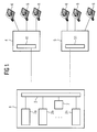
- FIG. 1 shows a structural diagram for schematic illustration a distributed communication system consisting of a Server 1 and two communication systems 4, 5. About the communication systems terminals 6 are connected, e.g. from telephones or data processing devices to the communication system.
- a connection of the communication systems 4, 5 with each other and with the server 1 can, for example, via a local Network (LAN: Local Area Network), a global network (WAN: Wide Area Network), e.g. the internet, or even over circuit switching communication networks, e.g. an ISDN network, respectively.
- LAN Local Area Network
- WAN Wide Area Network
- a bidirectional data transmission takes place by means of a so-called tunneling mechanism, in which the Messages from a communication system-specific networking protocol in messages of the corresponding transmission protocol (e.g. the IP protocol or the ISDN protocol) packed and transmitted over the network.
- the communication systems 4, 5 each have a local one Software interface 41, 51, which in the present embodiment is designed according to the CSTA standard. about such a software interface 41, 51 can be by means of external facilities of the respective communication system 4, 5, e.g. by activating or deactivating features, running communication applications or a Configure the respective communication system using a Administration application.
- server 1 3 implements the local software interfaces 41, 51 of the communication systems 4, 5 of the communication system to a single parent logical Mapping software interface. That way it turns out the communication system for communication applications running on the server 1 2a, ..., 2n like a single device with only one software interface.
- the communication applications 2a, ..., 2n is the total of Functions designated by the server 1 in interaction with the communication systems 4, 5 can, such as an activation or deactivation of performance features or an execution of administration applications.
- Each of the communication applications 2a, ..., 2n leads Functions through which certain resources of the communication system be occupied, e.g. one or more specific Numbers, trunk lines, etc.
- the central software interface 3 automatically detects in which of the communication systems 4, 5 within the communication system respective function is to be performed. For example, from Server 1 a feature for a specific number in the communication system 4 activated, the central determines Software interface 3 based on access to a Storage device 7 of the server 1 the address - for example the IP address - the corresponding communication system 4 in the network and sends the corresponding commands to carry out this feature on the communication system 4 over the network.
- the central software interface 3 thus carries out an assignment the respective resources of the communication system a corresponding communication system 4, 5 through and activated in this way the respective control function in the corresponding communication system 4, 5.
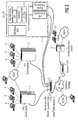
- FIG. 2 shows a structural diagram for schematic illustration an exemplary arrangement of a distributed - preferably private - communication system.
- the individual units of the communication system - in the present embodiment the server 1 and the communication systems 4, 5 - are networked via an Ethernet LAN and can use this Ethernet LAN Exchange signaling and voice data.
- a further communication system 8 for example a branch of a company, is over an IP network - for example the 'Internet' - connected to the Ethernet LAN, so that a global expansion of the - preferably private - communication system is made possible.
- a server based on the invention is located on the server 1 Software interface 3 implemented, in which the - in not shown in the figure - software interfaces distributed communication systems 4, 5, 8 can be summarized.
- the central software interface 3 is as central service provider represented by the simultaneously an implementation of the communication system-specific software interfaces - In the present embodiment of CSTA-oriented interfaces - to another software interface - In the present embodiment on a API interface (Application Programming Interface) of the Servers 1, e.g. to a TAPI interface (telephoning API), he follows.
- the central server 1 runs under the operating system 'Windows NT' from Microsoft, through which control of the individual functions of server 1, including the communication applications running on the server 1 2a, ..., 2n.
- a communication application 2a, ..., 2n via the summarized interfaces - just one system with a correspondingly high number of resources (e.g. subscriber lines, Exchange lines, phone numbers, etc.) sees.
- a communication application created for a single system 2a, ..., 2n can therefore also be used for a distributed one without change Communication system used and thus completely detached on the type of hardware above or one possibly distributed structure to be developed.
- the communication applications 2a, ..., 2n according to the present Invention can, as shown in the figure, also for individual systems that are spatially far apart, e.g. communication systems one branch of a company in another Cities and countries.
Landscapes
- Engineering & Computer Science (AREA)
- Signal Processing (AREA)
- Business, Economics & Management (AREA)
- Marketing (AREA)
- Telephonic Communication Services (AREA)
- Sub-Exchange Stations And Push- Button Telephones (AREA)
- Computer And Data Communications (AREA)
Abstract
Description
- Fig. 1:
- eine schematische Darstellung eines erfindungsgemäßen Kommunikationssystems, bestehend aus zwei Kommunikationsanlagen und einem zentralen Server; und
- Fig. 2:
- ein Beispiel für eine Anordnung eines verteilten Kommunikationssystems.
Claims (6)
- Kommunikationssystem, bestehend aus mehreren Kommunikationseinrichtungen (4,5) und einer zentralen Datenverarbeitungseinrichtung (1), die über ein Netzwerk miteinander verbunden sind,gekennzeichnet durch,bei dem durch die zentrale Datenverarbeitungseinrichtung (1) Kommunikationsanwendungen (2a,...,2n) ausführbar sind, undbei dem die Kommunikationseinrichtungen (4, 5) jeweils über eine lokale Schnittstelleneinheit (41, 51) verfügen, über die Steuerfunktionen in der jeweiligen Kommunikationseinrichtung (4, 5) steuerbar sind,
eine in der zentralen Datenverarbeitungseinrichtung (1) angeordnete zentrale Schnittstelleneinheit (3) zur Abbildung der jeweiligen Schnittstelleneinheiten (41, 51) der Kommunikationseinrichtungen (4,5) auf eine übergeordnete logische Schnittstelle. - Kommunikationssystem nach Anspruch 1,
dadurch gekennzeichnet, daß die Schnittstelleneinheit (3) automatisch erkennt, in welcher Kommunikationseinrichtung (4, 5) innerhalb des Kommunikationsnetzes eine jeweilige Steuerungsfunktion auszuführen ist und einen Datenaustausch zur Durchführung dieser Steuerungsfunktion mit der entsprechenden Kommunikationseinrichtung (4, 5) steuert. - Kommunikationssystem nach Anspruch 1 oder 2,
gekennzeichnet durch
eine in der zentralen Datenverarbeitungseinrichtung (1) angeordnete Speichervorrichtung (7) zum Speichern von für eine jeweilige Kommunikationseinrichtung (4, 5) verfügbaren Rufnummern in Beziehung zu einer die jeweiligen Kommunikationseinrichtung (4, 5) eindeutig identifizierende Adresse im Kommunikationssystem. - Kommunikationssystem nach Anspruch 1, 2 oder 3,
dadurch gekennzeichnet, daß die zentrale Schnittstelleneinheit (3) und die lokalen Schnittstelleneinheiten (41, 51) gemäß dem CSTA-Standard (Computer Supported Telecommunications Applications) ausgebildet sind. - Kommunikationssystem nach einem der vorhergehenden Ansprüche,
dadurch gekennzeichnet, daß das Netzwerk ein IP-orientiertes (Internet Protocol) Netzwerk ist. - Kommunikationssystem nach einem der vorhergehenden Ansprüche,
dadurch gekennzeichnet, daß die Kommunikationseinrichtungen (4,5) private Kommunikationsanlagen sind.
Applications Claiming Priority (2)
| Application Number | Priority Date | Filing Date | Title |
|---|---|---|---|
| DE10046320 | 2000-09-19 | ||
| DE10046320A DE10046320A1 (de) | 2000-09-19 | 2000-09-19 | Verteiltes Kommunikationssystem |
Publications (3)
| Publication Number | Publication Date |
|---|---|
| EP1189406A2 true EP1189406A2 (de) | 2002-03-20 |
| EP1189406A3 EP1189406A3 (de) | 2004-03-17 |
| EP1189406B1 EP1189406B1 (de) | 2018-01-10 |
Family
ID=7656775
Family Applications (1)
| Application Number | Title | Priority Date | Filing Date |
|---|---|---|---|
| EP01119543.5A Expired - Lifetime EP1189406B1 (de) | 2000-09-19 | 2001-08-14 | Verteiltes Kommunikationssystem mit zentraler CSTA-Schnittstelle zur Steuerung lokaler Funktionen |
Country Status (3)
| Country | Link |
|---|---|
| US (1) | US7099945B2 (de) |
| EP (1) | EP1189406B1 (de) |
| DE (1) | DE10046320A1 (de) |
Cited By (1)
| Publication number | Priority date | Publication date | Assignee | Title |
|---|---|---|---|---|
| EP3107260A1 (de) | 2015-06-18 | 2016-12-21 | Unify Patente GmbH & Co. KG | Verfahren zum aufbau einer telekommunikationsverbindung in einem telekommunikationssystem und telekommunikationssystem |
Families Citing this family (14)
| Publication number | Priority date | Publication date | Assignee | Title |
|---|---|---|---|---|
| US20020133528A1 (en) * | 1996-12-30 | 2002-09-19 | Smart Link Ltd. | Modem with distributed functionality |
| DE10159636B4 (de) * | 2001-12-05 | 2005-10-20 | Siemens Ag | Verfahren zur Steuerung und/oder Überwachung von Ressourcen und Verbindungen |
| DE10303865A1 (de) * | 2003-01-31 | 2004-08-26 | Deutsche Telekom Ag | WEB-basierendes Multimediales Virtuelles Call Center |
| US20050071494A1 (en) * | 2003-09-30 | 2005-03-31 | Rundquist William A. | Method and apparatus for providing fixed bandwidth communications over a local area network |
| FR2869491B1 (fr) * | 2004-04-22 | 2006-08-18 | Alcatel Sa | Reseau de telecommunication comportant plusieurs reseaux prives superposes ; autocommutateur pour la mise en oeuvre de ce reseau ; et centre d'appels d'urgence |
| US7912800B2 (en) * | 2006-08-29 | 2011-03-22 | Sap Ag | Deduction engine to determine what configuration management scoping questions to ask a user based on responses to one or more previous questions |
| US8065661B2 (en) | 2006-08-29 | 2011-11-22 | Sap Ag | Test engine |
| US7908589B2 (en) * | 2006-08-29 | 2011-03-15 | Sap Ag | Deployment |
| US8131644B2 (en) | 2006-08-29 | 2012-03-06 | Sap Ag | Formular update |
| WO2008039673A2 (en) * | 2006-09-19 | 2008-04-03 | Ithaca Technologies, Llc | A thin client implementation based on redirection of virtual i/o devices |
| US8135659B2 (en) | 2008-10-01 | 2012-03-13 | Sap Ag | System configuration comparison to identify process variation |
| US8396893B2 (en) | 2008-12-11 | 2013-03-12 | Sap Ag | Unified configuration of multiple applications |
| US8255429B2 (en) | 2008-12-17 | 2012-08-28 | Sap Ag | Configuration change without disruption of incomplete processes |
| US8584087B2 (en) * | 2009-12-11 | 2013-11-12 | Sap Ag | Application configuration deployment monitor |
Citations (1)
| Publication number | Priority date | Publication date | Assignee | Title |
|---|---|---|---|---|
| US5915012A (en) | 1997-01-14 | 1999-06-22 | Genesys, Telecommunications Laboratories, Inc. | System and method for operating a plurality of call centers |
Family Cites Families (7)
| Publication number | Priority date | Publication date | Assignee | Title |
|---|---|---|---|---|
| WO1996027266A1 (en) * | 1995-02-28 | 1996-09-06 | Philips Electronics N.V. | Telecommunication system |
| SE516325C2 (sv) | 1995-08-04 | 2001-12-17 | Telia Ab | Arrangemang för datorstyrd telefoni samt tillhörande publik server |
| US5978672A (en) | 1996-09-27 | 1999-11-02 | Global Mobility Systems, Inc. | Mobility extended telephone application programming interface and method of use |
| US6026085A (en) * | 1997-04-08 | 2000-02-15 | 3Com Corporation | Architecture to support a single system image across multiple network access servers |
| WO1999022491A1 (de) * | 1997-10-29 | 1999-05-06 | Siemens Schweiz Ag | Anordnung zum anschliessen von netzelementen von kommunikationsanlagen an ein telekommunikationsverwaltungsnetzwerk |
| US6804224B1 (en) * | 2000-02-29 | 2004-10-12 | 3Com Corporation | System and method for providing telephone service having private branch exchange features in a voice-over-data network telephony system |
| DE10044436B4 (de) * | 2000-09-08 | 2004-04-08 | Siemens Ag | Verfahren und Anordnung zum Betreiben einer CTI-Anwendung |
-
2000
- 2000-09-19 DE DE10046320A patent/DE10046320A1/de not_active Withdrawn
-
2001
- 2001-08-14 EP EP01119543.5A patent/EP1189406B1/de not_active Expired - Lifetime
- 2001-09-19 US US09/956,619 patent/US7099945B2/en not_active Expired - Lifetime
Patent Citations (1)
| Publication number | Priority date | Publication date | Assignee | Title |
|---|---|---|---|---|
| US5915012A (en) | 1997-01-14 | 1999-06-22 | Genesys, Telecommunications Laboratories, Inc. | System and method for operating a plurality of call centers |
Cited By (2)
| Publication number | Priority date | Publication date | Assignee | Title |
|---|---|---|---|---|
| EP3107260A1 (de) | 2015-06-18 | 2016-12-21 | Unify Patente GmbH & Co. KG | Verfahren zum aufbau einer telekommunikationsverbindung in einem telekommunikationssystem und telekommunikationssystem |
| DE102015007857A1 (de) | 2015-06-18 | 2016-12-22 | Unify Gmbh & Co. Kg | Verfahren zum Aufbau einer Telekommunikationsverbindung in einem Telekommunikationssystem und Telekommunikationssystem |
Also Published As
| Publication number | Publication date |
|---|---|
| DE10046320A1 (de) | 2002-04-04 |
| US20020073192A1 (en) | 2002-06-13 |
| US7099945B2 (en) | 2006-08-29 |
| EP1189406B1 (de) | 2018-01-10 |
| EP1189406A3 (de) | 2004-03-17 |
Similar Documents
| Publication | Publication Date | Title |
|---|---|---|
| EP0939537B1 (de) | Verfahren und Anordnung zum Bereitstellen von Leistungsmerkmalen über ein Kommunikationsnetz | |
| EP1189406A2 (de) | Verteiltes Kommunikationssystem | |
| DE10046339A1 (de) | Verfahren zum Betrieb eines Kommunikationssystems | |
| EP1305936B1 (de) | Vorrichtung und verfahren zur anrufumlenkung in telekommunikationsnetzen | |
| EP0734186B1 (de) | Verfahren zum Steuern eines Zugangsnetzes sowie Zugangsnetze und Vermittlungsstelle dafür | |
| DE10223980A1 (de) | Verfahren zur Leitweglenkung von Kommunikationsverbindungen | |
| EP1547345A1 (de) | Datenkommunikationssystem, rechner, sowie datenkommunikationsverfahren zum parallelen betrieb von standard-basierten und proprietären ressourcen | |
| EP1618704B1 (de) | Verfahren und steuerungsprogramm zum betrieb eines kommunikationsendgeräts für paketorientierte datenübermittlung | |
| DE10129322A1 (de) | Zentrale Administration eines Callcenters | |
| DE10046319A1 (de) | Vorrichtung und Verfahren zum Synchronisieren von Datenbanken in verteilten Kommunikationssystemen | |
| DE10053951B4 (de) | Verfahren und Router zur Einrichtung einer Verbindung über ein IP-orientiertes Netz | |
| DE10254904B3 (de) | Betriebsmodus für ein Kommunikationssystem | |
| EP1508240A1 (de) | Verfahren zur unterstützung einer kommunikationssystemweiten mobilität eines teilnehmers | |
| EP1215869A2 (de) | Verfahren und Anordnung zum Betrieb einer aus mehreren Teilnehmern bestehenden Teamkonfiguration | |
| DE19917383C1 (de) | Verfahren zur Steuerung von in einem Kommunikationsnetz angeordneten Einrichtungen | |
| DE60210945T2 (de) | Verfahren zum verbindungsaufbau in einem multimedianetzwerk | |
| EP1395024B1 (de) | Verfahren zur Bereitstellung von CTI-Diensten und/oder -Leistungsmerkmalen über einen eine Mehrzahl von Kommunikationsverbindungen umfassenden Kommunikationskanal | |
| EP1443741B1 (de) | WEB-basierendes Multimediales Virtuelles Call Center | |
| WO2004068830A1 (de) | Verfahren und anordnung zur steuerung und/oder überwachung eines an ein kommunikations-system angeschlossenen endgerätes | |
| EP1285541A2 (de) | Übermittlung von dienstesteuerinformationen über wenigstens eine zwischenstation | |
| EP1304855A2 (de) | Anordnung zur Steuerung und/oder Überwachung einer Kommunikationsanlage durch mindestens zwei Anwendungen | |
| EP0735785B1 (de) | Kommunikationssystem mit vermittlungstechnischen Servern | |
| EP1385341B1 (de) | Kommunikationsanlage und integrierte Serverbaugruppe für eine Kommunikationsanlage | |
| DE19712127A1 (de) | Vorrichtung zum Zwischenspeichern von Programmteilen in lokalen Netzen ohne lokale oder lokal zentralisierte Programm- oder Daten- und Programmspeicherung zur Beschleunigung der Programmabarbeitung und Optimierung der Datenübertragung zu entfernt stehenden zentralen Applikations- und Datenservern | |
| EP1189461A2 (de) | Verteiltes Kommunikationssystem |
Legal Events
| Date | Code | Title | Description |
|---|---|---|---|
| PUAI | Public reference made under article 153(3) epc to a published international application that has entered the european phase |
Free format text: ORIGINAL CODE: 0009012 |
|
| AK | Designated contracting states |
Kind code of ref document: A2 Designated state(s): AT BE CH CY DE DK ES FI FR GB GR IE IT LI LU MC NL PT SE TR |
|
| AX | Request for extension of the european patent |
Free format text: AL;LT;LV;MK;RO;SI |
|
| RIC1 | Information provided on ipc code assigned before grant |
Ipc: 7H 04M 3/42 A Ipc: 7H 04M 3/51 B |
|
| PUAL | Search report despatched |
Free format text: ORIGINAL CODE: 0009013 |
|
| AK | Designated contracting states |
Kind code of ref document: A3 Designated state(s): AT BE CH CY DE DK ES FI FR GB GR IE IT LI LU MC NL PT SE TR |
|
| AX | Request for extension of the european patent |
Extension state: AL LT LV MK RO SI |
|
| 17P | Request for examination filed |
Effective date: 20040322 |
|
| AKX | Designation fees paid |
Designated state(s): DE FR GB IT |
|
| 17Q | First examination report despatched |
Effective date: 20090223 |
|
| RAP1 | Party data changed (applicant data changed or rights of an application transferred) |
Owner name: SIEMENS ENTERPRISE COMMUNICATIONS GMBH & CO. KG |
|
| RAP1 | Party data changed (applicant data changed or rights of an application transferred) |
Owner name: UNIFY GMBH & CO. KG |
|
| RAP1 | Party data changed (applicant data changed or rights of an application transferred) |
Owner name: UNIFY GMBH & CO. KG |
|
| RIC1 | Information provided on ipc code assigned before grant |
Ipc: H04M 3/42 20060101AFI20170725BHEP Ipc: H04M 3/51 20060101ALI20170725BHEP Ipc: H04M 7/00 20060101ALN20170725BHEP |
|
| GRAP | Despatch of communication of intention to grant a patent |
Free format text: ORIGINAL CODE: EPIDOSNIGR1 |
|
| RIC1 | Information provided on ipc code assigned before grant |
Ipc: H04M 3/51 20060101ALI20170809BHEP Ipc: H04M 7/00 20060101ALN20170809BHEP Ipc: H04M 3/42 20060101AFI20170809BHEP |
|
| INTG | Intention to grant announced |
Effective date: 20170830 |
|
| GRAS | Grant fee paid |
Free format text: ORIGINAL CODE: EPIDOSNIGR3 |
|
| GRAA | (expected) grant |
Free format text: ORIGINAL CODE: 0009210 |
|
| AK | Designated contracting states |
Kind code of ref document: B1 Designated state(s): DE FR GB IT |
|
| REG | Reference to a national code |
Ref country code: GB Ref legal event code: FG4D Free format text: NOT ENGLISH |
|
| REG | Reference to a national code |
Ref country code: DE Ref legal event code: R096 Ref document number: 50116648 Country of ref document: DE |
|
| REG | Reference to a national code |
Ref country code: FR Ref legal event code: PLFP Year of fee payment: 18 |
|
| REG | Reference to a national code |
Ref country code: DE Ref legal event code: R097 Ref document number: 50116648 Country of ref document: DE |
|
| PG25 | Lapsed in a contracting state [announced via postgrant information from national office to epo] |
Ref country code: IT Free format text: LAPSE BECAUSE OF FAILURE TO SUBMIT A TRANSLATION OF THE DESCRIPTION OR TO PAY THE FEE WITHIN THE PRESCRIBED TIME-LIMIT Effective date: 20180110 |
|
| PGFP | Annual fee paid to national office [announced via postgrant information from national office to epo] |
Ref country code: FR Payment date: 20180824 Year of fee payment: 18 Ref country code: DE Payment date: 20180827 Year of fee payment: 18 |
|
| PLBE | No opposition filed within time limit |
Free format text: ORIGINAL CODE: 0009261 |
|
| STAA | Information on the status of an ep patent application or granted ep patent |
Free format text: STATUS: NO OPPOSITION FILED WITHIN TIME LIMIT |
|
| PGFP | Annual fee paid to national office [announced via postgrant information from national office to epo] |
Ref country code: GB Payment date: 20180828 Year of fee payment: 18 |
|
| 26N | No opposition filed |
Effective date: 20181011 |
|
| REG | Reference to a national code |
Ref country code: DE Ref legal event code: R119 Ref document number: 50116648 Country of ref document: DE |
|
| GBPC | Gb: european patent ceased through non-payment of renewal fee |
Effective date: 20190814 |
|
| PG25 | Lapsed in a contracting state [announced via postgrant information from national office to epo] |
Ref country code: FR Free format text: LAPSE BECAUSE OF NON-PAYMENT OF DUE FEES Effective date: 20190831 Ref country code: DE Free format text: LAPSE BECAUSE OF NON-PAYMENT OF DUE FEES Effective date: 20200303 |
|
| PG25 | Lapsed in a contracting state [announced via postgrant information from national office to epo] |
Ref country code: GB Free format text: LAPSE BECAUSE OF NON-PAYMENT OF DUE FEES Effective date: 20190814 |