EP1187152A2 - Rotary contactless connector and non-rotary contactless connector - Google Patents
Rotary contactless connector and non-rotary contactless connector Download PDFInfo
- Publication number
- EP1187152A2 EP1187152A2 EP01307343A EP01307343A EP1187152A2 EP 1187152 A2 EP1187152 A2 EP 1187152A2 EP 01307343 A EP01307343 A EP 01307343A EP 01307343 A EP01307343 A EP 01307343A EP 1187152 A2 EP1187152 A2 EP 1187152A2
- Authority
- EP
- European Patent Office
- Prior art keywords
- rotating
- rotary
- light emitting
- side light
- light receiving
- Prior art date
- Legal status (The legal status is an assumption and is not a legal conclusion. Google has not performed a legal analysis and makes no representation as to the accuracy of the status listed.)
- Granted
Links
Images


Classifications
-
- H—ELECTRICITY
- H01—ELECTRIC ELEMENTS
- H01F—MAGNETS; INDUCTANCES; TRANSFORMERS; SELECTION OF MATERIALS FOR THEIR MAGNETIC PROPERTIES
- H01F38/00—Adaptations of transformers or inductances for specific applications or functions
- H01F38/18—Rotary transformers
-
- H—ELECTRICITY
- H04—ELECTRIC COMMUNICATION TECHNIQUE
- H04B—TRANSMISSION
- H04B10/00—Transmission systems employing electromagnetic waves other than radio-waves, e.g. infrared, visible or ultraviolet light, or employing corpuscular radiation, e.g. quantum communication
- H04B10/80—Optical aspects relating to the use of optical transmission for specific applications, not provided for in groups H04B10/03 - H04B10/70, e.g. optical power feeding or optical transmission through water
- H04B10/801—Optical aspects relating to the use of optical transmission for specific applications, not provided for in groups H04B10/03 - H04B10/70, e.g. optical power feeding or optical transmission through water using optical interconnects, e.g. light coupled isolators, circuit board interconnections
-
- H—ELECTRICITY
- H01—ELECTRIC ELEMENTS
- H01F—MAGNETS; INDUCTANCES; TRANSFORMERS; SELECTION OF MATERIALS FOR THEIR MAGNETIC PROPERTIES
- H01F38/00—Adaptations of transformers or inductances for specific applications or functions
- H01F38/14—Inductive couplings
Definitions
- the present invention relates to a rotary contactless connector and a non-rotary contactless connector. More particularly, the present invention relates to a novel improvement for implementing contactless optical communication type single-channel or multi-channel signal transmission by using the rotary contactless connector and the non-rotary contactless connector.
- a rotor of a rotary transformer is equipped with a rotating-side light emitting or light receiving element, and electric power from an external source is supplied through the intermediary of the rotary transformer to an electric circuit for driving and controlling the rotating-side light emitting element or light receiving element.
- the electric power from an external source is supplied through the intermediary of a transformer to an electric circuit for driving a light emitting element or a light receiving element at a power-supplied side.
- signal transmission between a stationary-side unit and a rotating-side unit has been effected by connecting, for example, a rotating-side unit mounted on a gimbal mechanism having a plurality of rotating shafts or a single-shaft rotating platform and a stationary-side unit by using a rotary joint or slip ring and a contact connection type connector, and eventually by direct coupling to the contact connection type connector.
- connection method based on a contact type connector and the direct coupling wiring method for connecting a stationary unit and a rotating unit inevitably produce parasite drag generated due to the twist or rigidity of wiring even when only rotary motion of a finite angle is involved.
- the rotary joint or slip ring method has been posing such problems as larger sizes, higher cost, and lower environmental resistance although it has less likelihood of the occurrence of the parasite drag attributable to the twist or rigidity of wiring.
- the present invention has been made with a view toward solving the above problems, and it is an object of the present invention to provide a rotary contactless connector and non-rotary contactless connector adapted to perform optical communication type single- or multi-channel signal transmission in a contactless condition.
- a rotating-side light emitting element or light receiving element is mounted on a rotor or a connected member with its rotor to construct a data communication system for transmitting or receiving signals to or from the rotating unit.
- An electric power is supplied from the stationary unit through the intermediary of the rotary transformer.
- a light emitting element (or a light receiving element) is mounted on one of the two units or their connecting members, and a light receiving element (or a light emitting element) is mounted on the other of the two units or its connected members such that they oppose each other, thereby making up a data communication system to transfer signals between two units.
- a transformer that has an extremely small gap between the two noncontacting units is formed to supply electric power from one to the other.
- a rotary contactless connector including a rotary transformer composed of a rotor that has a rotary transformer winding and an annular stator that is concentric with the rotor and has a stator transformer winding, a rotating-side light emitting element or rotating-side light receiving element provided on the rotor, and a stationary-side light emitting element or a stationary-side light receiving element that is fixedly disposed to oppose the rotating-side light emitting element or the rotating-side light receiving element, wherein electric power is supplied to the rotor through the rotary transformer.
- a nonmagnetic and non-magnetized bearing is provided between the rotor and the annular stator.
- an electric circuit for driving the rotating-side light emitting element or the rotating-side light receiving element is provided, and electric power is supplied to the electric circuit through the rotary transformer.
- the rotating-side light emitting element or the rotating-side light receiving element is provided at the central position of the rotor.
- a plurality of the rotating-side light emitting elements or the rotating-side light receiving elements are provided at the concentric circumferential positions other than the central position of the rotor.
- a plurality of the rotating-side light emitting elements or the rotating-side light receiving elements are provided in the radial direction of the rotor.
- the electric circuit is provided in the rotor.
- a power output of the rotary transformer is divided into two outputs, one being directly coupled to the electric circuit, while the other being coupled to the electric circuit through the intermediary of storage means composed of a capacitor or a storage cell.
- the intermediary of storage means or the directly coupling line can be obviated with the specific requirement for electric power.
- a non-rotary contactless connector composing of two stationary members. These stationary members have the similar components except the electric parts between the transformer output and the electric circuit as below.
- One stationary member is the supplied side of the electric power by the name of first.
- the other stationary member is the supplying side of the electric power by the name of second.
- These stationary members each have a transformer winding, respectively.
- the transformer winding of the first stationary member is disposed to face with the transformer winding of the second stationary member for making up magnetic path.
- the electric power is supplied from the second to the first by means of a transformer.
- These stationary members have optical-electric elements, respectively.
- the optical-electric elements of a first stationary member are disposed to oppose to the optical-electric elements of a second stationary member for an optical communication.
- the optical-electric element is composed of light emitting elements or light receiving elements.
- An optical communication is performed between the first and second by means of the optical-electric elements.
- the electric power for driving the optical-electric elements on the first stationary member is supplied through the electric circuit from a first transformer output.
- the electric power to optical-electric elements on the second stationary member is supplied from an outside power unit.
- a power output end of the first transformer winding is divided into two outputs, one being directly coupled to the electric circuit, while the other being coupled to the electric circuit through the intermediary of storage means composed of a capacitor or a storage cell.
- the intermediary of storage means or the directly coupling line can be obviated with the specific requirement for electric power.
- reference numeral 1 denotes a rotary transformer acting as a contactless power supplying unit.
- the rotary transformer 1 is comprised of a hollow (or solid) rotor 3 having a transformer rotor-side winding 2, and an annular stator 5 that is provided concentrically with the rotor 3 and around the outer periphery of the rotor 3 and has a transformer stator-side winding 4.
- a nonmagnetic and non-magnetized bearing 6 formed of a plastics or the like is provided on the inner wall of the annular stator 5.
- the nonmagnetic and non-magnetized bearing 6 is disposed between the annular stator 5 and the rotor 3. If the bearing 6 is not used, then it is possible to connect the rotor 3 to a rotating member of an apparatus and connect the annular stator 5 to a stationary member of the apparatus, thereby to put the rotor 3 and the annular stator 5 in order.
- One or a plurality of light emitting elements 8 (or light receiving elements) of a rotating assembly are provided on a mounting plate 7.
- the mounting plate 7 is provided on the orthogonal surface of the rotor 3 to the axial direction of the rotating shaft of the rotor 3.
- An electric circuit 9 for driving the light emitting element (or receiving elements) 8 on the rotating assembly is mounted on the rotor 3, and the electric power can be supplied from outside via the rotary transformer 1.
- the electric circuit 9 may alternatively be provided on a rotating member other than the rotor 3. It is needless to say that the electric power supplied via the rotary transformer 1 can be supplied to other general circuits (not shown) in addition to the light emitting elements and light receiving elements.
- a stationary member 10 is provided on the surface of the annular stator 5 such that it opposes the rotor 3. Inside the stationary member 10, one or a plurality of stationary-side light receiving elements (or light emitting elements) 11 are provided to correspond to the rotating-side light emitting elements 8.
- the stationary member 10 can be secured to the annular stator 5 or attached to a stationary unit of an apparatus (not shown).
- the electric circuit 9 receives data sent from an apparatus in a rotary unit.
- the electric circuit 9 sends the emitting signals to the rotating-side light emitting elements 8, the rotating-side light emitting elements 8 emit light corresponding to the drive data signals, and the emitted light is received by the stationary-side light receiving elements 11.
- the data is transmitted from the rotating-side light emitting elements 8 to the stationary-side light receiving elements 11 by the optical communication method, allowing the contactless system to accomplish the same operation performed by a mechanical connector or slip ring.
- the dispositional relationship between the rotating-side light emitting elements 8 and the stationary-side light receiving elements 11 can be reversed, as previously mentioned.
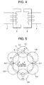
- Fig. 5 through Fig. 9 illustrate the relationship between the output range (denoted by r) of the rotating-side light emitting elements 8 and the light receiving range (denoted by R) of the stationary-side light receiving elements 11. It is possible to provide one element 8 and one element 11 at a central position to handle one channel. As shown in Fig. 5 and Fig. 6, however, if four rotating-side light emitting elements 8 and six stationary-side light receiving elements 11 are provided at concentric circumferential positions other than the central position, then it is also possible to provide a plurality of the elements 8 and 11 in the radial direction, as shown in Fig. 9.
- the four rotating-side light emitting elements 8 are set to 2.1, 2.2, 2.3, and 2.4 to assign them to channel 1, channel 2, channel 3, and channel 4, respectively.
- the output range of light emitting element 8 at the surface of the stationary-side light receiving elements 11 is denoted by a radius "r". Since four-channel outputs are required, it is necessary to provide four rotating-side light emitting elements 8. In order to restrain the occurrence of interruption and interference in receiving data, it is required to provide six stationary-side light receiving elements 11 (3.1, 3.2, 3.3, 3.4, 3.5, and 3.6) of the light receiving radius "R" at the apexes of an equilateral hexagon about a rotational axis. Referring to Fig.
- Optical communication can be performed by switching the outputs of the light receiving elements in sequence on the basis of a rotational angle in the similar manner as that described above.
- a rotating unit provides 2-channel outputs in the case of a finite-angle rotation. If two channels are on the same circumference, then three stationary-side light receiving elements 11 are installed, and the output of the middle stationary-side light receiving element 11 is switched on the basis of a rotational angle, as shown in Fig. 7, to perform optical communication. The same applies to the case shown in Fig. 8 where r>R.
- the light emitting elements 8 are on the same circumference.
- the light emitting elements for two channels is installed on two concentric circles, one on each, in the radial direction rather than on the same circumference, two-way, optical data communication will be possible as shown in Fig. 9.
- the optical communication based on the contactless data transmission can be achieved by properly disposing the light emitting elements and light receiving elements and appropriately switching the outputs of the optical elements by an electronic switching circuit or the like of the electric circuit 9.
- a rotary contactless connector can be obtained by combining a contactless power supplying unit and a contactless data communication unit.
- stator 5 is positioned around the outer periphery of the rotor 3 to represent a case where the rotor is located inside the stator. There are cases, however, where the rotor is located outside the stator, so that the stator 5 may be positioned on the inner periphery of the rotor 3. These cases are also included in the present invention.
- a nonmagnetic and non-magnetized bearing 6 is provided on the inner wall (or the outer wall if the stator 5 is position on the inner periphery of the rotor 3) of the annular stator 5.
- the nonmagnetic and non-magnetized bearing 6 is disposed between the annular stator 5 and the rotor 3. If the bearing 6 is not used, then it is possible to connect the rotor 3 to a rotating member of an apparatus to which the connector is applied, and connect the annular stator 5 to a stationary member of the apparatus, to which the connector is applied, thereby positioning the rotor 3 and the annular stator 5.
- An electric circuit 9 for driving the rotating-side light emitting element (or light receiving elements) 8 is mounted at an end of the rotor 3, and the electric power can be supplied from outside via the rotary transformer 1.
- the electric circuit 9 may alternatively be provided on a rotating member of the apparatus, to which the connector is applied, other than the rotor 3.
- the electric power from an external source which has passed through the rotary transformer 1 is supplied to the electric circuit 9 directly or through the intermediary of a storage means 12, as shown in Fig. 10, and can be supplied to other general unit 301 in addition to the light emitting elements and light receiving elements.
- the storage means 12 is composed of a capacitor or a storage cell, such as a battery.
- the storage means 12 has a buffer function for a power system.
- Fig. 10 shows the configuration wherein a rotational angle sensor 300, which may be composed of the light emitting elements 8 and light receiving elements 11 itself, and a rotating-side general unit 301 have been connected to the rotary transformer 1 shown in Fig. 1.
- the electric power from an external source is supplied to the electric circuit 9 through the intermediary of the storage means 12.
- the electric power from the storage means 12 can be supplied to the rotating-side light emitting elements 8 and the rotating-side general unit 301 via the electric circuit 9.
- the power output end of the rotary transformer 1 is divided into one end 1a and the other end 1b, and the one end 1a is directly connected to the electric circuit 9, while the other end 1b is connected to the electric circuit 9 through the intermediary of the storage means 12.
- a stationary member 10 is provided to cover the rotor 3 and the annular stator 5.
- One or a plurality of light receiving elements 11 (or light emitting elements) of the stationary side are provided at the positions of the stationary member 10 that optically oppose the rotating-side light emitting elements 8 (or light receiving elements).
- the stationary member 10 may be fixed to the annular stator 5 or mounted on the stationary unit of an apparatus (not shown).
- the electric circuit 9 receives data sent from an apparatus in a rotary unit.
- the electric circuit 9 sends the emitting signals to the rotating-side light emitting elements 8 (hereinafter, the rotating assembly will have the light emitting elements), the rotating-side light emitting elements 8 emit light corresponding to the drive data signals, and the emitted signals are received by the stationary-side light receiving elements 11 (hereinafter, the stationary unit will have the light receiving elements).
- the data is transmitted from the rotating-side light emitting elements 8 to the stationary-side light receiving elements 11 by optical communication method, allowing the contactless system to accomplish the same operation performed by a mechanical connector or slip ring.
- the dispositional relationship between the light emitting elements 8 and the light receiving elements 11 can be reversed, and provided side by side, thus enabling multi-channel bidirectional optical communication to be achieved.
- the data signals to emit to the rotating-side light emitting elements 8 and to be received by the stationary-side light receiving elements 11 can be taken out electromagnetically to the outside through the intermediary of the transformer rotor winding 2 or the transformer stator winding 4.
- a multi-channel bidirectional electromagnetical communication may be achieved.
- Fig. 11 shows the configuration of a non-rotary contactless connector according to another embodiment of the present invention.
- first stationary member 101 is set as the rotating member in the foregoing rotary contactless connector
- second stationary member 103 is set as the stationary member in the foregoing rotary contactless connector (the relationship may be reversed)
- the gap between the stationary members 101 and 103 corresponds to the gap between the rotor 3 and the annular stator 5 of the foregoing rotary contactless connector shown in Fig. 1.
- the rotary transformer 1 in the aforesaid rotary contactless connector shown in Fig. 10 corresponds to a stationary transformer 200, and the correspondence of the individual components of the rotating assembly and the stationary unit will be as follows.
- the foregoing transformer rotor winding 2 which is a component of the rotating assembly, corresponds to a first transformer winding 100
- the foregoing rotor 3 and the mounting plate 7 correspond to the first stationary member 101
- the foregoing rotating-side light emitting element 8 corresponds to a first light emitting element 110 (here, a first stationary member 101 will have the light emitting elements)
- the foregoing electric circuit 9 corresponds to an electric circuit 120
- the foregoing storage means 12 composed of a capacitor or a storage cell corresponds to a storage means 130 composed of a capacitor or a storage cell.
- the foregoing transformer stator winding 4 corresponds to a second transformer winding 102
- the foregoing annular stator 5 and the stationary member 10 correspond to a second stationary member 103
- the foregoing light receiving element 11 on the stationary unit corresponds to a second light receiving element 111 (here, a second stationary member 111 will have the light receiving elements).
- the electric power supplied to the electric circuit 120 by making use of the electromagnetic induction between the transformer windings 100 and 102 is supplied to the first light emitting element 110 through wiring (not shown), and can also be supplied to other general devices or the like in the power-supplied unit (not shown) by the electromagnetic coupling previously mentioned.
- the signals to emit to the first light emitting element 110 and to be received by the second light receiving element 111 can be taken out electromagnetically to the outside through the transformer winding 100 or 102.
- the non-rotary contactless connector and the rotary contactless connector basically share the same configuration and function except for the disposition of the light emitting elements and receiving elements for data communication. More specifically, the non-rotary contactless connector has no changes in relative position, so that simply installing it at an opposing position obviates the need for switching.
- the meaning of the term “contactless” also includes a condition wherein the first stationary member 101 and the second stationary member 103 shown in Fig. 11 are "in contact” on the contactless surface D whereon the first light emitting element 110 and the second light receiving element 111 oppose each other.
- the designation, non-rotary "contactless" connector implies that the connector is able to function also in the contactless condition.
- the configuration of the electric power source depends on a required condition of the electric power to be consumed.
- whether the configuration in which the electric power going through the intermediary of the rotary transformer 1 in the case of the rotary contactless connector or through the stationary transformer 200 in the case of the non-rotary contactless connector is always supplied directly to the electric circuit 9 or 120, or the configuration in which the electric power is supplied to the electric circuit 9 or 120 always through the intermediary of the storage means should be selected according to a required condition of the electric power to be consumed.
- the above configurations are obviously included in the configurations wherein the output power of the rotary transformer or the stationary transformer is supplied to the electric circuit directly and through the intermediary of the storage means.
- the electric circuit functions to supply electric power, generate light emitting commands and light receiving signals, and switch optical elements on the basis of rotational angles (the switching applies only to the rotary contactless connector).
- the functions are not described because the installation place of the electric circuit should not limited to within the connector.
- the existence of the storage means for the input of the electric circuit on the stationary unit remains optional. In the configurations shown in Fig. 1 through Fig. 11, the communication light between the light emitting elements and the light receiving elements advances in parallel to the axial direction of the rotating shaft.
- the rotating-side light emitting element 8 provided on the rotor 3 and the light receiving element 11 on the stationary unit provided on the annular stator 5 can be positioned on the same plane so that they oppose each other, as shown in Fig. 12, the light path direction of the communication light between the elements 8 and 11 can be made orthogonal to the axial direction of the rotating shaft of the rotor 3.
- the rotary contactless connector in accordance with the present invention provides the following advantages.
- the combination of the rotary transformer and the means for coupling optical elements allows data communication between the optical elements in a contactless mode while receiving electric power supplied from an external source.
- This arrangement makes it possible to transfer data easily and reliably in the contactless mode in detectors, drive units, etc. in various types of apparatuses.
- the supply of electric power and the transfer of signals can be accomplished in the contactless mode under a restricted condition.
Landscapes
- Engineering & Computer Science (AREA)
- Power Engineering (AREA)
- Physics & Mathematics (AREA)
- Electromagnetism (AREA)
- Computer Networks & Wireless Communication (AREA)
- Signal Processing (AREA)
- Optical Communication System (AREA)
- Photo Coupler, Interrupter, Optical-To-Optical Conversion Devices (AREA)
- Arrangements For Transmission Of Measured Signals (AREA)
- Coupling Device And Connection With Printed Circuit (AREA)
- Mechanical Coupling Of Light Guides (AREA)
Abstract
Description
- The present invention relates to a rotary contactless connector and a non-rotary contactless connector. More particularly, the present invention relates to a novel improvement for implementing contactless optical communication type single-channel or multi-channel signal transmission by using the rotary contactless connector and the non-rotary contactless connector. In the case of the rotary contactless connector, a rotor of a rotary transformer is equipped with a rotating-side light emitting or light receiving element, and electric power from an external source is supplied through the intermediary of the rotary transformer to an electric circuit for driving and controlling the rotating-side light emitting element or light receiving element. In the case of the non-rotary contactless connector, the electric power from an external source is supplied through the intermediary of a transformer to an electric circuit for driving a light emitting element or a light receiving element at a power-supplied side.
- Hitherto, signal transmission between a stationary-side unit and a rotating-side unit has been effected by connecting, for example, a rotating-side unit mounted on a gimbal mechanism having a plurality of rotating shafts or a single-shaft rotating platform and a stationary-side unit by using a rotary joint or slip ring and a contact connection type connector, and eventually by direct coupling to the contact connection type connector.
- Great efforts have been made to obviate the need for the use of wiring, and the contactless type data transfer has become significantly easier owing to the progress in the recent infrared communication technology. However, it has been difficult to achieve supply of electric power from a stationary unit to a rotating unit in a contactless mode, and the need for the wire for supplying power still remains, making it difficult to completely eliminate wiring. Furthermore, contactless type data transfer using an optical connector or optical coupler that combines a light emitting member and a light receiving member has also been having a similar difficulty.
- The conventional transmission of signals between a stationary unit and a rotating unit described above has been presenting the following problems.
- Specifically, the connection method based on a contact type connector and the direct coupling wiring method for connecting a stationary unit and a rotating unit inevitably produce parasite drag generated due to the twist or rigidity of wiring even when only rotary motion of a finite angle is involved.
- The rotary joint or slip ring method has been posing such problems as larger sizes, higher cost, and lower environmental resistance although it has less likelihood of the occurrence of the parasite drag attributable to the twist or rigidity of wiring.
- Furthermore, use of a modulation type infrared communication device for transmitting a required quantity of data to be transmitted or received by multiple channels would lead to a lower data transmission rate with resultant reduced transmission capacity and higher cost. Inevitably using a non-modulation method to avoid the above-mentioned problem, in turn, has been posing the problem of interference among channels.
- The present invention has been made with a view toward solving the above problems, and it is an object of the present invention to provide a rotary contactless connector and non-rotary contactless connector adapted to perform optical communication type single- or multi-channel signal transmission in a contactless condition.
- In the rotary contactless connector for signal transfer between a stationary unit and a rotating unit, a rotating-side light emitting element or light receiving element is mounted on a rotor or a connected member with its rotor to construct a data communication system for transmitting or receiving signals to or from the rotating unit. An electric power is supplied from the stationary unit through the intermediary of the rotary transformer.
- For the non-rotary contactless connector to transfer signals between two faced units that are not in contact and whose relative faced positions remain unchanged, a light emitting element (or a light receiving element) is mounted on one of the two units or their connecting members, and a light receiving element (or a light emitting element) is mounted on the other of the two units or its connected members such that they oppose each other, thereby making up a data communication system to transfer signals between two units. For a power system, a transformer that has an extremely small gap between the two noncontacting units is formed to supply electric power from one to the other.
- According to one aspect of the present invention, there is provided a rotary contactless connector including a rotary transformer composed of a rotor that has a rotary transformer winding and an annular stator that is concentric with the rotor and has a stator transformer winding, a rotating-side light emitting element or rotating-side light receiving element provided on the rotor, and a stationary-side light emitting element or a stationary-side light receiving element that is fixedly disposed to oppose the rotating-side light emitting element or the rotating-side light receiving element, wherein electric power is supplied to the rotor through the rotary transformer.
- Preferably, a nonmagnetic and non-magnetized bearing is provided between the rotor and the annular stator.
- Preferably, an electric circuit for driving the rotating-side light emitting element or the rotating-side light receiving element is provided, and electric power is supplied to the electric circuit through the rotary transformer.
- Preferably, the rotating-side light emitting element or the rotating-side light receiving element is provided at the central position of the rotor.
- Preferably, a plurality of the rotating-side light emitting elements or the rotating-side light receiving elements are provided at the concentric circumferential positions other than the central position of the rotor.
- Preferably, a plurality of the rotating-side light emitting elements or the rotating-side light receiving elements are provided in the radial direction of the rotor.
- Preferably, the electric circuit is provided in the rotor.
- To perform optical communication, a power output of the rotary transformer is divided into two outputs, one being directly coupled to the electric circuit, while the other being coupled to the electric circuit through the intermediary of storage means composed of a capacitor or a storage cell.
- Preferably, the intermediary of storage means or the directly coupling line can be obviated with the specific requirement for electric power.
- According to another aspect of the present invention, a non-rotary contactless connector is provided composing of two stationary members. These stationary members have the similar components except the electric parts between the transformer output and the electric circuit as below. One stationary member is the supplied side of the electric power by the name of first. The other stationary member is the supplying side of the electric power by the name of second. These stationary members each have a transformer winding, respectively. The transformer winding of the first stationary member is disposed to face with the transformer winding of the second stationary member for making up magnetic path. The electric power is supplied from the second to the first by means of a transformer.
- These stationary members have optical-electric elements, respectively. The optical-electric elements of a first stationary member are disposed to oppose to the optical-electric elements of a second stationary member for an optical communication. The optical-electric element is composed of light emitting elements or light receiving elements. An optical communication is performed between the first and second by means of the optical-electric elements. The electric power for driving the optical-electric elements on the first stationary member is supplied through the electric circuit from a first transformer output. The electric power to optical-electric elements on the second stationary member is supplied from an outside power unit.
- Preferably, a power output end of the first transformer winding is divided into two outputs, one being directly coupled to the electric circuit, while the other being coupled to the electric circuit through the intermediary of storage means composed of a capacitor or a storage cell.
- Preferably, the intermediary of storage means or the directly coupling line can be obviated with the specific requirement for electric power.
-
- Fig. 1 is a sectional view of a rotary contactless connector according to an embodiment of the present invention;
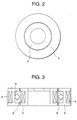
- Fig. 2 is a top plan view of an essential section of the rotary contactless connector shown in Fig. 1;
- Fig. 3 is a sectional view of the essential section of the rotary contactless connector shown in Fig. 1;
- Fig. 4 is a schematic diagram of the essential section of the rotary contactless connector shown in Fig. 1;
- Fig. 5 is a diagram showing a light receiving range and an output range of a light emitting element at the stationary-side light receiving element surface of the rotary-side shown in Fig. 1;
- Fig. 6 is a diagram showing a configuration applied when r>R in the diagram shown in Fig. 5;
- Fig. 7 is a diagram showing a configuration applied when R≥r in the case of a finite rotational angle;
- Fig. 8 illustrates an example of the disposition when r>R in Fig. 7 and shows the diagram that a rotary unit is provided with a light receiving element, while a stationary unit is provided with a light emitting element in Fig. 7;
- Fig. 9 illustrates an example of the disposition of a light receiving element when a light emitting element is concentrically disposed;
- Fig. 10 is a block diagram showing the buffer function of a power system, communication data flow, etc in the present invention;
- Fig. 11 shows the configuration of a non-rotary contactless connector according to a further embodiment of the present invention; and
- Fig. 12 shows the configuration of still another embodiment of the present invention in Fig. 1.
-
- Preferred embodiments of a rotary contactless connector and non-rotary contactless connector in accordance with the present invention will be described in conjunction with the accompanying drawings.
- Referring to Fig. 1 through Fig. 4,
reference numeral 1 denotes a rotary transformer acting as a contactless power supplying unit. Therotary transformer 1 is comprised of a hollow (or solid)rotor 3 having a transformer rotor-side winding 2, and anannular stator 5 that is provided concentrically with therotor 3 and around the outer periphery of therotor 3 and has a transformer stator-side winding 4. - A nonmagnetic and non-magnetized bearing 6 formed of a plastics or the like is provided on the inner wall of the
annular stator 5. The nonmagnetic andnon-magnetized bearing 6 is disposed between theannular stator 5 and therotor 3. If thebearing 6 is not used, then it is possible to connect therotor 3 to a rotating member of an apparatus and connect theannular stator 5 to a stationary member of the apparatus, thereby to put therotor 3 and theannular stator 5 in order. - One or a plurality of light emitting elements 8 (or light receiving elements) of a rotating assembly are provided on a mounting
plate 7. The mountingplate 7 is provided on the orthogonal surface of therotor 3 to the axial direction of the rotating shaft of therotor 3. Anelectric circuit 9 for driving the light emitting element (or receiving elements) 8 on the rotating assembly is mounted on therotor 3, and the electric power can be supplied from outside via therotary transformer 1. Theelectric circuit 9 may alternatively be provided on a rotating member other than therotor 3. It is needless to say that the electric power supplied via therotary transformer 1 can be supplied to other general circuits (not shown) in addition to the light emitting elements and light receiving elements. - A
stationary member 10 is provided on the surface of theannular stator 5 such that it opposes therotor 3. Inside thestationary member 10, one or a plurality of stationary-side light receiving elements (or light emitting elements) 11 are provided to correspond to the rotating-sidelight emitting elements 8. Thestationary member 10 can be secured to theannular stator 5 or attached to a stationary unit of an apparatus (not shown). - In the above status, when electric power is supplied from outside to the
electric circuit 9 through the intermediary of therotary transformer 1. Theelectric circuit 9 receives data sent from an apparatus in a rotary unit. When theelectric circuit 9 sends the emitting signals to the rotating-sidelight emitting elements 8, the rotating-sidelight emitting elements 8 emit light corresponding to the drive data signals, and the emitted light is received by the stationary-sidelight receiving elements 11. Thus, the data is transmitted from the rotating-sidelight emitting elements 8 to the stationary-sidelight receiving elements 11 by the optical communication method, allowing the contactless system to accomplish the same operation performed by a mechanical connector or slip ring. The dispositional relationship between the rotating-sidelight emitting elements 8 and the stationary-sidelight receiving elements 11 can be reversed, as previously mentioned. - Fig. 5 through Fig. 9 illustrate the relationship between the output range (denoted by r) of the rotating-side
light emitting elements 8 and the light receiving range (denoted by R) of the stationary-sidelight receiving elements 11. It is possible to provide oneelement 8 and oneelement 11 at a central position to handle one channel. As shown in Fig. 5 and Fig. 6, however, if four rotating-sidelight emitting elements 8 and six stationary-sidelight receiving elements 11 are provided at concentric circumferential positions other than the central position, then it is also possible to provide a plurality of theelements - In the case shown in Fig. 5, the four rotating-side
light emitting elements 8 are set to 2.1, 2.2, 2.3, and 2.4 to assign them tochannel 1,channel 2,channel 3, andchannel 4, respectively. The output range of light emittingelement 8 at the surface of the stationary-sidelight receiving elements 11 is denoted by a radius "r". Since four-channel outputs are required, it is necessary to provide four rotating-sidelight emitting elements 8. In order to restrain the occurrence of interruption and interference in receiving data, it is required to provide six stationary-side light receiving elements 11 (3.1, 3.2, 3.3, 3.4, 3.5, and 3.6) of the light receiving radius "R" at the apexes of an equilateral hexagon about a rotational axis. Referring to Fig. 5, when the rotating-sidelight emitting elements 8, 2.1, starts to enter the circle of the light receiving element 3.2 due to rotation, the rotating-sidelight emitting element 8, 2.2, which was in the circle of 3.2, will have left the circle by then. The output of the stationary-sidelight receiving element 11, 3.2, which has been forchannel 2 until then, is switched to the output for channel 1 (the rotating-sidelight emitting element 8, 2.1) by a switching signal from theelectric circuit 9. For the remaining channels, the outputs of the light receiving elements are switched in a similar manner in sequence as the rotation is carried out. This allows data communication to be accomplished without interruption or interference in the transfer of the output signals of the channels. Fig. 5 illustrates the example wherein R≥r, since the output range r of the rotating-sidelight emitting elements 8 is frequently smaller than the input range R of the stationary-sidelight receiving elements 11. Fig. 6 illustrates a case where r>R. Optical communication can be performed by switching the outputs of the light receiving elements in sequence on the basis of a rotational angle in the similar manner as that described above. - The descriptions will now be given of an embodiment wherein a rotating unit provides 2-channel outputs in the case of a finite-angle rotation. If two channels are on the same circumference, then three stationary-side
light receiving elements 11 are installed, and the output of the middle stationary-sidelight receiving element 11 is switched on the basis of a rotational angle, as shown in Fig. 7, to perform optical communication. The same applies to the case shown in Fig. 8 where r>R. - All the embodiments described above refer to the cases where the rotating-side
light emitting elements 8 are installed on the rotating unit, while the stationary-sidelight receiving elements 11 are installed on the stationary unit. Conversely, if thelight receiving elements 11 are installed on the rotating unit, while thelight emitting elements 8 are installed on the stationary unit, then the rotating unit and the stationary unit shown in Fig. 8 will be switched and regarded as the stationary unit and the rotating unit, respectively, as previously mentioned. Thus, two-way optical data communication will be possible. - Furthermore, in all the embodiments of Fig. 7 and Fig. 8, the
light emitting elements 8 are on the same circumference. Alternatively, however, if the light emitting elements for two channels is installed on two concentric circles, one on each, in the radial direction rather than on the same circumference, two-way, optical data communication will be possible as shown in Fig. 9. - As described above, the optical communication based on the contactless data transmission, including two-way communication, can be achieved by properly disposing the light emitting elements and light receiving elements and appropriately switching the outputs of the optical elements by an electronic switching circuit or the like of the
electric circuit 9. - Thus, a rotary contactless connector can be obtained by combining a contactless power supplying unit and a contactless data communication unit.
- In the drawing, the
stator 5 is positioned around the outer periphery of therotor 3 to represent a case where the rotor is located inside the stator. There are cases, however, where the rotor is located outside the stator, so that thestator 5 may be positioned on the inner periphery of therotor 3. These cases are also included in the present invention. - A nonmagnetic and
non-magnetized bearing 6 is provided on the inner wall (or the outer wall if thestator 5 is position on the inner periphery of the rotor 3) of theannular stator 5. The nonmagnetic andnon-magnetized bearing 6 is disposed between theannular stator 5 and therotor 3. If thebearing 6 is not used, then it is possible to connect therotor 3 to a rotating member of an apparatus to which the connector is applied, and connect theannular stator 5 to a stationary member of the apparatus, to which the connector is applied, thereby positioning therotor 3 and theannular stator 5. - An
electric circuit 9 for driving the rotating-side light emitting element (or light receiving elements) 8 is mounted at an end of therotor 3, and the electric power can be supplied from outside via therotary transformer 1. Theelectric circuit 9 may alternatively be provided on a rotating member of the apparatus, to which the connector is applied, other than therotor 3. - It is needless to say that the electric power from an external source, which has passed through the
rotary transformer 1, is supplied to theelectric circuit 9 directly or through the intermediary of a storage means 12, as shown in Fig. 10, and can be supplied to othergeneral unit 301 in addition to the light emitting elements and light receiving elements. The storage means 12 is composed of a capacitor or a storage cell, such as a battery. - Thus, the storage means 12 has a buffer function for a power system. Fig. 10 shows the configuration wherein a
rotational angle sensor 300, which may be composed of thelight emitting elements 8 andlight receiving elements 11 itself, and a rotating-sidegeneral unit 301 have been connected to therotary transformer 1 shown in Fig. 1. - More specifically, the electric power from an external source is supplied to the
electric circuit 9 through the intermediary of the storage means 12. The electric power from the storage means 12 can be supplied to the rotating-sidelight emitting elements 8 and the rotating-sidegeneral unit 301 via theelectric circuit 9. For this reason, the power output end of therotary transformer 1 is divided into oneend 1a and theother end 1b, and the oneend 1a is directly connected to theelectric circuit 9, while theother end 1b is connected to theelectric circuit 9 through the intermediary of the storage means 12. - Outside the
annular stator 5, astationary member 10 is provided to cover therotor 3 and theannular stator 5. One or a plurality of light receiving elements 11 (or light emitting elements) of the stationary side are provided at the positions of thestationary member 10 that optically oppose the rotating-side light emitting elements 8 (or light receiving elements). Thestationary member 10 may be fixed to theannular stator 5 or mounted on the stationary unit of an apparatus (not shown). - When the external electric power from an external source is supplied to the
electric circuit 9 through the intermediary of therotary transformer 1, theelectric circuit 9 receives data sent from an apparatus in a rotary unit. When theelectric circuit 9 sends the emitting signals to the rotating-side light emitting elements 8 (hereinafter, the rotating assembly will have the light emitting elements), the rotating-sidelight emitting elements 8 emit light corresponding to the drive data signals, and the emitted signals are received by the stationary-side light receiving elements 11 (hereinafter, the stationary unit will have the light receiving elements). Thus, the data is transmitted from the rotating-sidelight emitting elements 8 to the stationary-sidelight receiving elements 11 by optical communication method, allowing the contactless system to accomplish the same operation performed by a mechanical connector or slip ring. The dispositional relationship between thelight emitting elements 8 and thelight receiving elements 11 can be reversed, and provided side by side, thus enabling multi-channel bidirectional optical communication to be achieved. - Moreover, the data signals to emit to the rotating-side
light emitting elements 8 and to be received by the stationary-sidelight receiving elements 11 can be taken out electromagnetically to the outside through the intermediary of the transformer rotor winding 2 or the transformer stator winding 4. Thus a multi-channel bidirectional electromagnetical communication may be achieved. - Fig. 11 shows the configuration of a non-rotary contactless connector according to another embodiment of the present invention.
- If a first
stationary member 101 is set as the rotating member in the foregoing rotary contactless connector, while a secondstationary member 103 is set as the stationary member in the foregoing rotary contactless connector (the relationship may be reversed), then the gap between thestationary members rotor 3 and theannular stator 5 of the foregoing rotary contactless connector shown in Fig. 1. - More specifically, electric power is supplied from the second
stationary member 103 to the firststationary member 101, so that the firststationary member 101 is on the power-supplied side. According to this setting, therotary transformer 1 in the aforesaid rotary contactless connector shown in Fig. 10 corresponds to astationary transformer 200, and the correspondence of the individual components of the rotating assembly and the stationary unit will be as follows. The foregoing transformer rotor winding 2, which is a component of the rotating assembly, corresponds to a first transformer winding 100, the foregoingrotor 3 and the mountingplate 7 correspond to the firststationary member 101, the foregoing rotating-sidelight emitting element 8 corresponds to a first light emitting element 110 (here, a firststationary member 101 will have the light emitting elements), the foregoingelectric circuit 9 corresponds to anelectric circuit 120, and the foregoing storage means 12 composed of a capacitor or a storage cell corresponds to a storage means 130 composed of a capacitor or a storage cell. Similarly, in the stationary unit, the foregoing transformer stator winding 4 corresponds to a second transformer winding 102, the foregoingannular stator 5 and thestationary member 10 correspond to a secondstationary member 103, and the foregoinglight receiving element 11 on the stationary unit corresponds to a second light receiving element 111 (here, a secondstationary member 111 will have the light receiving elements). - It is needless to say, therefore, that the electric power supplied to the
electric circuit 120 by making use of the electromagnetic induction between thetransformer windings light emitting element 110 through wiring (not shown), and can also be supplied to other general devices or the like in the power-supplied unit (not shown) by the electromagnetic coupling previously mentioned. - Furthermore, the signals to emit to the first
light emitting element 110 and to be received by the secondlight receiving element 111 can be taken out electromagnetically to the outside through the transformer winding 100 or 102. - As is obvious from the correspondence of the components mentioned above, the non-rotary contactless connector and the rotary contactless connector basically share the same configuration and function except for the disposition of the light emitting elements and receiving elements for data communication. More specifically, the non-rotary contactless connector has no changes in relative position, so that simply installing it at an opposing position obviates the need for switching. The meaning of the term "contactless" also includes a condition wherein the first
stationary member 101 and the secondstationary member 103 shown in Fig. 11 are "in contact" on the contactless surface D whereon the firstlight emitting element 110 and the secondlight receiving element 111 oppose each other. The designation, non-rotary "contactless" connector implies that the connector is able to function also in the contactless condition. - In both the rotary contactless connector and the non-rotary contactless connector, the configuration of the electric power source depends on a required condition of the electric power to be consumed. To be more specific, whether the configuration in which the electric power going through the intermediary of the
rotary transformer 1 in the case of the rotary contactless connector or through thestationary transformer 200 in the case of the non-rotary contactless connector is always supplied directly to theelectric circuit electric circuit - The descriptions have been given of the
electric circuit 9 on the rotating unit in the case of the rotary contactless connector shown in Fig. 1 and Figs. 2 through 9, and of theelectric circuit 120 on the power-supplied unit in the case of the non-rotary contactless connector shown in Fig. 11. It is needless to say that the electric circuit is also provided on the stationary unit in the case of the rotary contactless connector, or on the power-supplying unit in the case of the non-rotary contactless connector, although it is not shown. The functions of the electric circuit on the stationary unit or the power-supplying unit are identical to the functions of theelectric circuit light emitting element 8 provided on therotor 3 and thelight receiving element 11 on the stationary unit provided on theannular stator 5 can be positioned on the same plane so that they oppose each other, as shown in Fig. 12, the light path direction of the communication light between theelements rotor 3. - By virtue of the features described above, the rotary contactless connector in accordance with the present invention provides the following advantages.
- The combination of the rotary transformer and the means for coupling optical elements allows data communication between the optical elements in a contactless mode while receiving electric power supplied from an external source. This arrangement makes it possible to transfer data easily and reliably in the contactless mode in detectors, drive units, etc. in various types of apparatuses. In the non-rotary contactless connector, the supply of electric power and the transfer of signals can be accomplished in the contactless mode under a restricted condition.
Claims (11)
- A rotary contactless connector comprising:a rotary transformer (1) composed of a rotor (3) that has a transformer rotary winding (2) and an annular stator (5) that is concentric with the rotor (3) and has a transformer stator winding (4);a rotating-side light emitting element (8) or a rotating-side light receiving element provided on the rotor (3); anda stationary-side light emitting element or a stationary-side light receiving element (11) that is fixedly disposed to oppose the rotating-side light emitting element (8) or the rotating-side light receiving element,
wherein electric power is supplied to the rotor (3) through the rotary transformer (1) to perform optical communication, anda power output of the rotary transformer (1) is divided into two outputs, one (1a) being directly coupled to the electric circuit (9), while the other (1b) being coupled to the electric circuit (9) through the intermediary of storage means (12) composed of a capacitor or a storage cell. - A rotary contactless connector according to Claim 1, wherein a nonmagnetic and non-magnetized bearing (6) is provided between the rotor (3) and the annular stator (5).
- A rotary contactless connector according to Claim 1, further comprising an electric circuit (9) for driving the rotating-side light emitting element (8) or the rotating-side light receiving element,
wherein electric power is supplied to the electric circuit (9) through the intermediary of the rotary transformer (1). - A rotary contactless connector according to Claim 3, whereinthe electric circuit (9) is provided in the rotor (3).
- A rotary contactless connector according to Claim 1, wherein the rotating-side light emitting element (8) or the rotating-side light receiving element is provided at the central position of the rotor (3).
- A rotary contactless connector according to Claim 1, wherein a plurality of the rotating-side light emitting elements (8) or the rotating-side light receiving elements are provided at the concentric circumferential positions other than the central position of the rotor (3).
- A rotary contactless connector according to Claim 5, wherein a plurality of the rotating-side light emitting elements (8) or the rotating-side light receiving elements are provided at the concentric circumferential positions other than the central position of the rotor (3).
- A rotary contactless connector according to Claim 1, wherein a plurality of the rotating-side light emitting elements (8) or the rotating-side light receiving elements are provided in the radial direction of the rotor (3).
- A rotary contactless connector according to Claim 5, wherein a plurality of the rotating-side light emitting elements (8) or the rotating-side light receiving elements are provided in the radial direction of the rotor (3).
- A non-rotary contactless connector comprising:a first stationary member (101) having a transformer first winding (100);a second stationary member (103) that is disposed to oppose the first stationary member (101) and has a transformer second winding (102);a first light emitting element (110) or light receiving element provided on the first stationary member (101); anda second light receiving element (111) or light emitting element provided on the second stationary member (103),
wherein electric power is supplied to the first stationary member (101) from the second stationary member (103) on a power-supplying side by means of magnetic coupling between the transformer windings (100 and 102) to perform optical communication,an electric circuit (120) for driving the first light emitting element (110) or light receiving element in the first stationary member (101) is provided, andelectric power is supplied to the electric circuit (120) through the intermediary of the transformer first winding (100) or the transformer second winding (102). - A non-rotary contactless connector according to Claim 10, wherein a power output of the transformer first winding (100) is divided into two outputs, and one is directly coupled to the electric circuit (120), while the other is coupled to the electric circuit (120) through the intermediary of storage means (130) composed of a capacitor or a storage cell.
Applications Claiming Priority (4)
| Application Number | Priority Date | Filing Date | Title |
|---|---|---|---|
| JP2000259051A JP3598053B2 (en) | 2000-08-29 | 2000-08-29 | Rotary non-contact connector |
| JP2000259051 | 2000-08-29 | ||
| JP2001076684 | 2001-03-16 | ||
| JP2001076684A JP3533375B2 (en) | 2001-03-16 | 2001-03-16 | Rotary non-contact connector |
Publications (4)
| Publication Number | Publication Date |
|---|---|
| EP1187152A2 true EP1187152A2 (en) | 2002-03-13 |
| EP1187152A3 EP1187152A3 (en) | 2003-11-26 |
| EP1187152B1 EP1187152B1 (en) | 2010-08-18 |
| EP1187152B8 EP1187152B8 (en) | 2010-12-15 |
Family
ID=26598683
Family Applications (1)
| Application Number | Title | Priority Date | Filing Date |
|---|---|---|---|
| EP01307343A Expired - Lifetime EP1187152B8 (en) | 2000-08-29 | 2001-08-29 | Rotary contactless connector |
Country Status (4)
| Country | Link |
|---|---|
| US (1) | US6759759B2 (en) |
| EP (1) | EP1187152B8 (en) |
| AT (1) | ATE478428T1 (en) |
| DE (1) | DE60142819D1 (en) |
Cited By (5)
| Publication number | Priority date | Publication date | Assignee | Title |
|---|---|---|---|---|
| EP1646166A2 (en) | 2004-10-05 | 2006-04-12 | Chubu Nihon Maruko Co.,Ltd | Contactless connector |
| KR100769882B1 (en) * | 2005-10-03 | 2007-10-24 | 추부 니혼 마루코 컴퍼니 리미티드 | Contactless connector |
| KR100800076B1 (en) * | 2005-09-27 | 2008-01-31 | 추부 니혼 마루코 컴퍼니 리미티드 | Contactless connector |
| EP2073408A1 (en) * | 2007-12-17 | 2009-06-24 | Siemens Aktiengesellschaft | Device for transmitting light signals and corresponding method |
| WO2010124165A1 (en) * | 2009-04-23 | 2010-10-28 | Battelle Memorial Institute | Inductively and optically coupled interconnect |
Families Citing this family (18)
| Publication number | Priority date | Publication date | Assignee | Title |
|---|---|---|---|---|
| DE10302435B3 (en) * | 2003-01-21 | 2004-07-01 | Schleifring Und Apparatebau Gmbh | Optical gigabit rotary transmitter with free inner diameter |
| US8238755B2 (en) * | 2005-07-08 | 2012-08-07 | Panasonic Corporation | Dual wiring system |
| US7194154B2 (en) * | 2005-08-15 | 2007-03-20 | Sony Ericsson Mobile Communications Ab | Optical connector |
| US7957786B2 (en) * | 2005-08-15 | 2011-06-07 | General Electric Company | Methods and apparatus for communicating signals between portions of an apparatus in relative movement to one another |
| US20070077783A1 (en) * | 2005-09-30 | 2007-04-05 | Trw Automotive U.S. Llc | Rotary connector system |
| US7813602B2 (en) * | 2007-09-10 | 2010-10-12 | Chubu Nihon Maruko Co., Ltd. | Non-contact connector |
| JP2009130773A (en) * | 2007-11-27 | 2009-06-11 | Chubu Nippon Maruco Kk | Non-contact connector |
| DE102008008113A1 (en) * | 2008-02-08 | 2009-08-13 | Schaeffler Kg | Non-magnetizable rolling bearing component of an austenitic material and method for producing such a rolling bearing component |
| US20100148505A1 (en) * | 2008-12-16 | 2010-06-17 | Dunlap Gregory M | Contact-less power and signal transmission device for a high power level transformer |
| DE102009053584A1 (en) | 2009-11-17 | 2011-05-19 | Airbus Operations Gmbh | Carrier system for receiving containers in a vehicle and use of a carrier system in an aircraft |
| US8041225B2 (en) * | 2009-12-21 | 2011-10-18 | General Electric Company | Contactless infrared data transmission for wind turbines |
| JP2011205878A (en) * | 2009-12-25 | 2011-10-13 | Canon Anelva Corp | Vacuum actuator and substrate transport robot |
| DE102011005339A1 (en) * | 2011-03-10 | 2012-09-13 | Komet Group Gmbh | Rotary transmission for machine tools |
| US8953298B2 (en) | 2011-11-30 | 2015-02-10 | Taiwan Semiconductor Manufacturing Co., Ltd. | Electrostatic chuck robotic system |
| TWI551870B (en) * | 2015-02-26 | 2016-10-01 | 思達科技股份有限公司 | Test assembly and the method of manufacturing the same |
| FR3056366B1 (en) * | 2016-09-20 | 2019-08-30 | Thales | ROTATING COLLECTOR |
| EP3886988A1 (en) | 2018-11-30 | 2021-10-06 | Merck Sharp & Dohme Corp. | 9-substituted amino triazolo quinazoline derivatives as adenosine receptor antagonists, pharmaceutical compositions and their use |
| CN117650843B (en) * | 2024-01-30 | 2024-04-30 | 陕西旋星电子科技有限公司 | Non-contact optical communication slip ring and optical device side surface arrangement method thereof |
Citations (9)
| Publication number | Priority date | Publication date | Assignee | Title |
|---|---|---|---|---|
| US4236086A (en) * | 1977-11-25 | 1980-11-25 | Siemens Aktiengesellschaft | Apparatus for the detection and processing of electric signals |
| US4514645A (en) * | 1982-02-19 | 1985-04-30 | Hitachi, Ltd. | Power supply system for automotive parts having a rotary component |
| US4778147A (en) * | 1985-07-27 | 1988-10-18 | Mitsubishi Jidosha Kogyo Kabushiki Kaisha | Electromagnetic solenoid |
| US4837556A (en) * | 1985-04-15 | 1989-06-06 | Kabushiki Kaisha Nihon Denzai Kogyo Kenkyusho | Signal transmission device |
| EP0357829A1 (en) * | 1988-09-09 | 1990-03-14 | Toppan Moore Company, Ltd. | Non-contacting power supplying system |
| EP0540750A1 (en) * | 1991-05-21 | 1993-05-12 | Kabushiki Kaisha Yaskawa Denki | Apparatus for feeding power in non-contact way |
| US5451856A (en) * | 1993-07-28 | 1995-09-19 | Societe Hispano Suiza | Device for the transmission of electrical power signals to a rotary assembly |
| US5818188A (en) * | 1992-06-18 | 1998-10-06 | Kabushiki Kaisha Yaskawa Denki | Noncontacting electric power transfer apparatus, noncontacting signal transfer apparatus, split-type mechanical apparatus employing these transfer apparatus, and a control method for controlling same |
| EP0926690A1 (en) * | 1997-07-03 | 1999-06-30 | The Furukawa Electric Co., Ltd. | Split transformer and transmission controller comprising the split transformer |
Family Cites Families (5)
| Publication number | Priority date | Publication date | Assignee | Title |
|---|---|---|---|---|
| US5031992A (en) * | 1989-08-18 | 1991-07-16 | Ampex Corporation | Multiple parallel channel rotary optical coupler |
| EP0477891B1 (en) * | 1990-09-26 | 1996-07-10 | Matsushita Electric Industrial Co., Ltd. | Power supply apparatus for television receiver set and television receiver set including the same |
| JPH07222489A (en) * | 1994-01-27 | 1995-08-18 | Matsushita Electric Ind Co Ltd | Motor driving apparatus |
| US5521444A (en) * | 1994-11-30 | 1996-05-28 | Honeywell Inc. | Apparatus for transferring electrical power from a stationary device to a rotating device without the use of brushes or contacts |
| US5811898A (en) * | 1995-12-21 | 1998-09-22 | Siemens Electric Limited | Rotary actuator |
-
2001
- 2001-08-24 US US09/935,710 patent/US6759759B2/en not_active Expired - Lifetime
- 2001-08-29 EP EP01307343A patent/EP1187152B8/en not_active Expired - Lifetime
- 2001-08-29 DE DE60142819T patent/DE60142819D1/en not_active Expired - Lifetime
- 2001-08-29 AT AT01307343T patent/ATE478428T1/en not_active IP Right Cessation
Patent Citations (9)
| Publication number | Priority date | Publication date | Assignee | Title |
|---|---|---|---|---|
| US4236086A (en) * | 1977-11-25 | 1980-11-25 | Siemens Aktiengesellschaft | Apparatus for the detection and processing of electric signals |
| US4514645A (en) * | 1982-02-19 | 1985-04-30 | Hitachi, Ltd. | Power supply system for automotive parts having a rotary component |
| US4837556A (en) * | 1985-04-15 | 1989-06-06 | Kabushiki Kaisha Nihon Denzai Kogyo Kenkyusho | Signal transmission device |
| US4778147A (en) * | 1985-07-27 | 1988-10-18 | Mitsubishi Jidosha Kogyo Kabushiki Kaisha | Electromagnetic solenoid |
| EP0357829A1 (en) * | 1988-09-09 | 1990-03-14 | Toppan Moore Company, Ltd. | Non-contacting power supplying system |
| EP0540750A1 (en) * | 1991-05-21 | 1993-05-12 | Kabushiki Kaisha Yaskawa Denki | Apparatus for feeding power in non-contact way |
| US5818188A (en) * | 1992-06-18 | 1998-10-06 | Kabushiki Kaisha Yaskawa Denki | Noncontacting electric power transfer apparatus, noncontacting signal transfer apparatus, split-type mechanical apparatus employing these transfer apparatus, and a control method for controlling same |
| US5451856A (en) * | 1993-07-28 | 1995-09-19 | Societe Hispano Suiza | Device for the transmission of electrical power signals to a rotary assembly |
| EP0926690A1 (en) * | 1997-07-03 | 1999-06-30 | The Furukawa Electric Co., Ltd. | Split transformer and transmission controller comprising the split transformer |
Cited By (9)
| Publication number | Priority date | Publication date | Assignee | Title |
|---|---|---|---|---|
| EP1646166A2 (en) | 2004-10-05 | 2006-04-12 | Chubu Nihon Maruko Co.,Ltd | Contactless connector |
| EP1646166A3 (en) * | 2004-10-05 | 2006-05-10 | Chubu Nihon Maruko Co.,Ltd | Contactless connector |
| US7539372B2 (en) | 2004-10-05 | 2009-05-26 | Chubu Nihon Maruko Co., Ltd. | Contactless connector |
| CN1758389B (en) * | 2004-10-05 | 2011-11-16 | 中部日本丸子株式会社 | Contactless connector |
| KR100800076B1 (en) * | 2005-09-27 | 2008-01-31 | 추부 니혼 마루코 컴퍼니 리미티드 | Contactless connector |
| KR100769882B1 (en) * | 2005-10-03 | 2007-10-24 | 추부 니혼 마루코 컴퍼니 리미티드 | Contactless connector |
| EP2073408A1 (en) * | 2007-12-17 | 2009-06-24 | Siemens Aktiengesellschaft | Device for transmitting light signals and corresponding method |
| US8026474B2 (en) | 2007-12-17 | 2011-09-27 | Siemens Aktiengesellschaft | Device for transferring light signals between two elements relatively movable to one another |
| WO2010124165A1 (en) * | 2009-04-23 | 2010-10-28 | Battelle Memorial Institute | Inductively and optically coupled interconnect |
Also Published As
| Publication number | Publication date |
|---|---|
| EP1187152B1 (en) | 2010-08-18 |
| EP1187152A3 (en) | 2003-11-26 |
| US20040012471A1 (en) | 2004-01-22 |
| DE60142819D1 (en) | 2010-09-30 |
| US6759759B2 (en) | 2004-07-06 |
| EP1187152B8 (en) | 2010-12-15 |
| ATE478428T1 (en) | 2010-09-15 |
Similar Documents
| Publication | Publication Date | Title |
|---|---|---|
| EP1187152B1 (en) | Rotary contactless connector | |
| US6950633B2 (en) | Rotary non-contact connector and non-rotary non-contact connector | |
| JP4892544B2 (en) | Rotary transmitter | |
| US4939400A (en) | Transmission apparatus having split-coil type coaxial coupler | |
| JP4080503B2 (en) | Non-contact connector | |
| EP3852235A1 (en) | Contactless power supply and data communication device, and system having rotation-drive unit, using same | |
| US5272350A (en) | Rotary coupler effecting power and information exchange | |
| CN101058376B (en) | Spooling device | |
| KR100713161B1 (en) | Contactless connector | |
| JP3533375B2 (en) | Rotary non-contact connector | |
| CN211209705U (en) | Non-contact slip ring for high-speed communication | |
| JP3598053B2 (en) | Rotary non-contact connector | |
| CN111758048A (en) | Laser radar system, operating method for a laser radar system and operating device | |
| JPH08222459A (en) | Non-contact motion transmission device | |
| JP3259919B2 (en) | Rotating device with built-in power and signal transmission mechanism | |
| KR102636715B1 (en) | Non-contact power supply and data communication device and rotary driving lidar system using the same | |
| JP7420418B2 (en) | Contactless power supply and data communication device, and rotary drive lidar system using the same | |
| EP0988751A1 (en) | Coupler for transmitting signals across a rotating interface | |
| US9551840B2 (en) | Provision of an optical rotating joint installation | |
| TW201719059A (en) | Rotating shaft device | |
| CA3092602A1 (en) | System and method for operating a system having at least one first mobile part and one second mobile part | |
| CN214707438U (en) | In-wheel motor and vehicle | |
| CN109164833B (en) | Angle control system capable of carrying out automatic adjustment and control method thereof | |
| JP2002298275A (en) | Magnetic rotary link | |
| JPH0678478A (en) | Signal transmitter |
Legal Events
| Date | Code | Title | Description |
|---|---|---|---|
| PUAI | Public reference made under article 153(3) epc to a published international application that has entered the european phase |
Free format text: ORIGINAL CODE: 0009012 |
|
| AK | Designated contracting states |
Kind code of ref document: A2 Designated state(s): AT BE CH CY DE DK ES FI FR GB GR IE IT LI LU MC NL PT SE TR |
|
| AX | Request for extension of the european patent |
Free format text: AL;LT;LV;MK;RO;SI |
|
| PUAL | Search report despatched |
Free format text: ORIGINAL CODE: 0009013 |
|
| AK | Designated contracting states |
Kind code of ref document: A3 Designated state(s): AT BE CH CY DE DK ES FI FR GB GR IE IT LI LU MC NL PT SE TR |
|
| AX | Request for extension of the european patent |
Extension state: AL LT LV MK RO SI |
|
| 17P | Request for examination filed |
Effective date: 20040210 |
|
| 17Q | First examination report despatched |
Effective date: 20040407 |
|
| AKX | Designation fees paid |
Designated state(s): AT BE CH CY DE DK ES FI FR GB GR IE IT LI LU MC NL PT SE TR |
|
| RTI1 | Title (correction) |
Free format text: ROTARY CONTACTLESS CONNECTOR |
|
| RIN1 | Information on inventor provided before grant (corrected) |
Inventor name: KOITABASHI, HIROYUKI Inventor name: ARAI, AKIFUMI Inventor name: KOJIMA, TETSUYA |
|
| GRAP | Despatch of communication of intention to grant a patent |
Free format text: ORIGINAL CODE: EPIDOSNIGR1 |
|
| RAP1 | Party data changed (applicant data changed or rights of an application transferred) |
Owner name: CHUBU NIHON MARUKO CO.,LTD Owner name: TAMAGAWA SEIKI KABUSHIKI KAISHA |
|
| GRAS | Grant fee paid |
Free format text: ORIGINAL CODE: EPIDOSNIGR3 |
|
| GRAA | (expected) grant |
Free format text: ORIGINAL CODE: 0009210 |
|
| AK | Designated contracting states |
Kind code of ref document: B1 Designated state(s): AT BE CH CY DE DK ES FI FR GB GR IE IT LI LU MC NL PT SE TR |
|
| REG | Reference to a national code |
Ref country code: GB Ref legal event code: FG4D |
|
| REG | Reference to a national code |
Ref country code: CH Ref legal event code: EP |
|
| REG | Reference to a national code |
Ref country code: IE Ref legal event code: FG4D |
|
| REF | Corresponds to: |
Ref document number: 60142819 Country of ref document: DE Date of ref document: 20100930 Kind code of ref document: P |
|
| REG | Reference to a national code |
Ref country code: CH Ref legal event code: PUE Owner name: CHUBU NIHON MARUKO CO., LTD. Free format text: CHUBUNIHON MARUKO CO., LTD.#OOYASUMI#IIDA-SHI NAGANO-KEN (JP) -TRANSFER TO- CHUBU NIHON MARUKO CO., LTD.#23-3, NOGUCHI KOMAKI-SHI#AICHI-KEN (JP) |
|
| RAP2 | Party data changed (patent owner data changed or rights of a patent transferred) |
Owner name: CHUBU NIHON MARUKO CO., LTD. |
|
| REG | Reference to a national code |
Ref country code: NL Ref legal event code: T3 |
|
| REG | Reference to a national code |
Ref country code: SE Ref legal event code: TRGR |
|
| REG | Reference to a national code |
Ref country code: CH Ref legal event code: NV Representative=s name: NOVAGRAAF SWITZERLAND S.A. |
|
| PG25 | Lapsed in a contracting state [announced via postgrant information from national office to epo] |
Ref country code: AT Free format text: LAPSE BECAUSE OF FAILURE TO SUBMIT A TRANSLATION OF THE DESCRIPTION OR TO PAY THE FEE WITHIN THE PRESCRIBED TIME-LIMIT Effective date: 20100818 Ref country code: FI Free format text: LAPSE BECAUSE OF FAILURE TO SUBMIT A TRANSLATION OF THE DESCRIPTION OR TO PAY THE FEE WITHIN THE PRESCRIBED TIME-LIMIT Effective date: 20100818 |
|
| PG25 | Lapsed in a contracting state [announced via postgrant information from national office to epo] |
Ref country code: CY Free format text: LAPSE BECAUSE OF FAILURE TO SUBMIT A TRANSLATION OF THE DESCRIPTION OR TO PAY THE FEE WITHIN THE PRESCRIBED TIME-LIMIT Effective date: 20100818 Ref country code: PT Free format text: LAPSE BECAUSE OF FAILURE TO SUBMIT A TRANSLATION OF THE DESCRIPTION OR TO PAY THE FEE WITHIN THE PRESCRIBED TIME-LIMIT Effective date: 20101220 |
|
| PG25 | Lapsed in a contracting state [announced via postgrant information from national office to epo] |
Ref country code: GR Free format text: LAPSE BECAUSE OF FAILURE TO SUBMIT A TRANSLATION OF THE DESCRIPTION OR TO PAY THE FEE WITHIN THE PRESCRIBED TIME-LIMIT Effective date: 20101119 Ref country code: MC Free format text: LAPSE BECAUSE OF NON-PAYMENT OF DUE FEES Effective date: 20100831 |
|
| PG25 | Lapsed in a contracting state [announced via postgrant information from national office to epo] |
Ref country code: DK Free format text: LAPSE BECAUSE OF FAILURE TO SUBMIT A TRANSLATION OF THE DESCRIPTION OR TO PAY THE FEE WITHIN THE PRESCRIBED TIME-LIMIT Effective date: 20100818 |
|
| PLBE | No opposition filed within time limit |
Free format text: ORIGINAL CODE: 0009261 |
|
| STAA | Information on the status of an ep patent application or granted ep patent |
Free format text: STATUS: NO OPPOSITION FILED WITHIN TIME LIMIT |
|
| PG25 | Lapsed in a contracting state [announced via postgrant information from national office to epo] |
Ref country code: ES Free format text: LAPSE BECAUSE OF FAILURE TO SUBMIT A TRANSLATION OF THE DESCRIPTION OR TO PAY THE FEE WITHIN THE PRESCRIBED TIME-LIMIT Effective date: 20101129 |
|
| REG | Reference to a national code |
Ref country code: CH Ref legal event code: PCAR Free format text: NOVAGRAAF SWITZERLAND SA;CHEMIN DE L'ECHO 3;1213 ONEX (CH) |
|
| 26N | No opposition filed |
Effective date: 20110519 |
|
| PG25 | Lapsed in a contracting state [announced via postgrant information from national office to epo] |
Ref country code: IE Free format text: LAPSE BECAUSE OF NON-PAYMENT OF DUE FEES Effective date: 20100829 |
|
| REG | Reference to a national code |
Ref country code: DE Ref legal event code: R097 Ref document number: 60142819 Country of ref document: DE Effective date: 20110519 |
|
| PG25 | Lapsed in a contracting state [announced via postgrant information from national office to epo] |
Ref country code: LU Free format text: LAPSE BECAUSE OF NON-PAYMENT OF DUE FEES Effective date: 20100829 |
|
| PG25 | Lapsed in a contracting state [announced via postgrant information from national office to epo] |
Ref country code: TR Free format text: LAPSE BECAUSE OF FAILURE TO SUBMIT A TRANSLATION OF THE DESCRIPTION OR TO PAY THE FEE WITHIN THE PRESCRIBED TIME-LIMIT Effective date: 20100818 |
|
| PGFP | Annual fee paid to national office [announced via postgrant information from national office to epo] |
Ref country code: NL Payment date: 20150809 Year of fee payment: 15 |
|
| PGFP | Annual fee paid to national office [announced via postgrant information from national office to epo] |
Ref country code: SE Payment date: 20150811 Year of fee payment: 15 |
|
| PGFP | Annual fee paid to national office [announced via postgrant information from national office to epo] |
Ref country code: IT Payment date: 20150827 Year of fee payment: 15 |
|
| PGFP | Annual fee paid to national office [announced via postgrant information from national office to epo] |
Ref country code: BE Payment date: 20150811 Year of fee payment: 15 |
|
| REG | Reference to a national code |
Ref country code: FR Ref legal event code: PLFP Year of fee payment: 16 |
|
| PGFP | Annual fee paid to national office [announced via postgrant information from national office to epo] |
Ref country code: GB Payment date: 20160824 Year of fee payment: 16 Ref country code: DE Payment date: 20160823 Year of fee payment: 16 Ref country code: CH Payment date: 20160812 Year of fee payment: 16 |
|
| PGFP | Annual fee paid to national office [announced via postgrant information from national office to epo] |
Ref country code: FR Payment date: 20160712 Year of fee payment: 16 |
|
| PG25 | Lapsed in a contracting state [announced via postgrant information from national office to epo] |
Ref country code: BE Free format text: LAPSE BECAUSE OF NON-PAYMENT OF DUE FEES Effective date: 20160831 |
|
| REG | Reference to a national code |
Ref country code: SE Ref legal event code: EUG |
|
| REG | Reference to a national code |
Ref country code: NL Ref legal event code: MM Effective date: 20160901 |
|
| PG25 | Lapsed in a contracting state [announced via postgrant information from national office to epo] |
Ref country code: SE Free format text: LAPSE BECAUSE OF NON-PAYMENT OF DUE FEES Effective date: 20160830 |
|
| PG25 | Lapsed in a contracting state [announced via postgrant information from national office to epo] |
Ref country code: NL Free format text: LAPSE BECAUSE OF NON-PAYMENT OF DUE FEES Effective date: 20160901 |
|
| PG25 | Lapsed in a contracting state [announced via postgrant information from national office to epo] |
Ref country code: IT Free format text: LAPSE BECAUSE OF NON-PAYMENT OF DUE FEES Effective date: 20160829 |
|
| REG | Reference to a national code |
Ref country code: DE Ref legal event code: R119 Ref document number: 60142819 Country of ref document: DE |
|
| REG | Reference to a national code |
Ref country code: CH Ref legal event code: PL |
|
| GBPC | Gb: european patent ceased through non-payment of renewal fee |
Effective date: 20170829 |
|
| PG25 | Lapsed in a contracting state [announced via postgrant information from national office to epo] |
Ref country code: LI Free format text: LAPSE BECAUSE OF NON-PAYMENT OF DUE FEES Effective date: 20170831 Ref country code: CH Free format text: LAPSE BECAUSE OF NON-PAYMENT OF DUE FEES Effective date: 20170831 |
|
| REG | Reference to a national code |
Ref country code: FR Ref legal event code: ST Effective date: 20180430 |
|
| PG25 | Lapsed in a contracting state [announced via postgrant information from national office to epo] |
Ref country code: GB Free format text: LAPSE BECAUSE OF NON-PAYMENT OF DUE FEES Effective date: 20170829 Ref country code: DE Free format text: LAPSE BECAUSE OF NON-PAYMENT OF DUE FEES Effective date: 20180301 |
|
| PG25 | Lapsed in a contracting state [announced via postgrant information from national office to epo] |
Ref country code: FR Free format text: LAPSE BECAUSE OF NON-PAYMENT OF DUE FEES Effective date: 20170831 |