EP1183103B1 - Apparatus and method for the precise location of reaction plates - Google Patents
Apparatus and method for the precise location of reaction plates Download PDFInfo
- Publication number
- EP1183103B1 EP1183103B1 EP00936314A EP00936314A EP1183103B1 EP 1183103 B1 EP1183103 B1 EP 1183103B1 EP 00936314 A EP00936314 A EP 00936314A EP 00936314 A EP00936314 A EP 00936314A EP 1183103 B1 EP1183103 B1 EP 1183103B1
- Authority
- EP
- European Patent Office
- Prior art keywords
- plate
- wells
- support surface
- locator structure
- wall surfaces
- Prior art date
- Legal status (The legal status is an assumption and is not a legal conclusion. Google has not performed a legal analysis and makes no representation as to the accuracy of the status listed.)
- Expired - Lifetime
Links
Images


Classifications
-
- B—PERFORMING OPERATIONS; TRANSPORTING
- B01—PHYSICAL OR CHEMICAL PROCESSES OR APPARATUS IN GENERAL
- B01L—CHEMICAL OR PHYSICAL LABORATORY APPARATUS FOR GENERAL USE
- B01L3/00—Containers or dishes for laboratory use, e.g. laboratory glassware; Droppers
- B01L3/50—Containers for the purpose of retaining a material to be analysed, e.g. test tubes
- B01L3/508—Containers for the purpose of retaining a material to be analysed, e.g. test tubes rigid containers not provided for above
- B01L3/5085—Containers for the purpose of retaining a material to be analysed, e.g. test tubes rigid containers not provided for above for multiple samples, e.g. microtitration plates
-
- G—PHYSICS
- G01—MEASURING; TESTING
- G01N—INVESTIGATING OR ANALYSING MATERIALS BY DETERMINING THEIR CHEMICAL OR PHYSICAL PROPERTIES
- G01N35/00—Automatic analysis not limited to methods or materials provided for in any single one of groups G01N1/00 - G01N33/00; Handling materials therefor
- G01N35/10—Devices for transferring samples or any liquids to, in, or from, the analysis apparatus, e.g. suction devices, injection devices
- G01N35/1065—Multiple transfer devices
-
- Y—GENERAL TAGGING OF NEW TECHNOLOGICAL DEVELOPMENTS; GENERAL TAGGING OF CROSS-SECTIONAL TECHNOLOGIES SPANNING OVER SEVERAL SECTIONS OF THE IPC; TECHNICAL SUBJECTS COVERED BY FORMER USPC CROSS-REFERENCE ART COLLECTIONS [XRACs] AND DIGESTS
- Y10—TECHNICAL SUBJECTS COVERED BY FORMER USPC
- Y10T—TECHNICAL SUBJECTS COVERED BY FORMER US CLASSIFICATION
- Y10T436/00—Chemistry: analytical and immunological testing
- Y10T436/11—Automated chemical analysis
- Y10T436/113332—Automated chemical analysis with conveyance of sample along a test line in a container or rack
- Y10T436/114165—Automated chemical analysis with conveyance of sample along a test line in a container or rack with step of insertion or removal from test line
-
- Y—GENERAL TAGGING OF NEW TECHNOLOGICAL DEVELOPMENTS; GENERAL TAGGING OF CROSS-SECTIONAL TECHNOLOGIES SPANNING OVER SEVERAL SECTIONS OF THE IPC; TECHNICAL SUBJECTS COVERED BY FORMER USPC CROSS-REFERENCE ART COLLECTIONS [XRACs] AND DIGESTS
- Y10—TECHNICAL SUBJECTS COVERED BY FORMER USPC
- Y10T—TECHNICAL SUBJECTS COVERED BY FORMER US CLASSIFICATION
- Y10T436/00—Chemistry: analytical and immunological testing
- Y10T436/25—Chemistry: analytical and immunological testing including sample preparation
- Y10T436/2575—Volumetric liquid transfer
Definitions
- the present invention relates to the positioning of multi-well plates in laboratory machines. More particularly, the invention provides an apparatus and method for accurately locating a multi-well plate at a plate-support region of a laboratory machine, so that one or more acting members, e.g., an array of pipette tips or optical readers, can operate on the individual wells.
- one or more acting members e.g., an array of pipette tips or optical readers
- reagent transfers e.g., aspiration and dispensing
- mixing and stirring as well as reading the results of each assay.
- each sample was processed in its own, separate container, such as a tube or flask, in a largely manual fashion.
- the early methods generally provided for the processing of only one or a few samples at a time and, thus, were time consuming and labor intensive.
- arrays of reaction wells e.g., 96 wells arranged in an 8 x 12 array
- parallel processing brought a substantial increase in throughput, many fundamental laboratory procedures continued to be carried out in a largely manual fashion.
- One aspect of the present invention provides an improvement for a microplate apparatus having (i) a tray or plate defining an array of sample wells (also referred to as a microtiter plate), (ii) a plate-handling machine having (a) a plate-support region, e.g., a surface or deck, and (b) a sample-handling or reading device which operates on individual wells in the plate, and (iii) a control unit for controlling the position of the device with respect to defined coordinates (points of reference) on the plate-support surface.
- An improved plate locating and aligning arrangement including locator structure disposed on the plate-support surface for engaging the exterior wall surfaces of one or more wells, when the plate is placed on the plate-support surface, so as to fix the position of each well at a known location with respect to the defined coordinates.
- the locator structure includes at least one projection extending from the plate-support surface. In another embodiment, two or more projections (e.g., 2, 3 or 4) extend from the plate-support surface.
- One or more of the projections and the exterior wall surfaces of one or more wells can be configured with complementary shaped regions.
- the complementary shaped regions can fit closely against one another.
- one or more of the projections taper on progressing toward their upper regions (e.g., generally having a cone shape) and one or more wells taper on progressing toward their lower regions.
- the exterior wall surfaces of the tapered wells in this arrangement, define one or more tapered recesses, each being adapted to receive one of the tapered projections.
- the exterior wall surfaces of four wells can define a recess into which a generally cone-shaped projection can fit.
- each projection defines a central cavity (e.g., a hole or bore) that opens away from the plate-support surface. The cavity, in this arrangement, is configured to receive a lower region of the exterior wall surfaces of a well.
- the locator structure includes no more than one projection for every four wells of the well array. In another embodiment, the locator structure includes no more than one projection for every six wells of the well array.
- the locating and aligning arrangement of the invention can further include a biasing assembly operable, with a multi-well plate positioned on the plate-support surface, to urge the locator structure against regions of the exterior wall surfaces of the wells.
- the biasing assembly includes a vacuum source and a flow line for communicating the vacuum source with a lower side of a plate, with the plate positioned on the plate-support surface.
- the vacuum source in this embodiment, is operable to draw the plate against the plate-support surface.
- biasing assemblies that are pneumatic, hydraulic, motorized, magnetic, and/or spring-loaded.
- the sample-handling or reading device is attached to a support.
- the support is adapted for movement, preferably by automated means (e.g., by way of a robotic arm or cross-bar assembly, and/or a motorized carriage directed by a control unit, or the like).
- the movable support in this embodiment, is adapted to transport the sample-handling or reading device toward and away from a position suitable for addressing and operating on individual wells fixed at known locations with respect to the defined coordinates on the plate-support surface.
- the sample-handling or reading device remains substantially stationary, and the plate-support surface is adapted for movement toward and away from a position whereat the device can operate on individual wells.
- the sample-handling or reading device can include, for example, a plurality of sample-handling or reading members (also referred to herein as acting members) disposed in an array that is alignable with at least a portion of the well array, with the wells fixed at such known locations.
- sample-handling or reading members also referred to herein as acting members
- one or more of the acting members are pipette tips.
- one or more of the acting members are optical sensors or readers.
- an improved plate locating and aligning arrangement for use with a microplate apparatus, includes locator structure defined by the plate-support surface, with the locator structure being configured to engagingly receive a region of the exterior wall surfaces of at least one of the wells, when the plate is placed on the plate-support surface, so as to fix the position of each well at a known location with respect to defined coordinates on the plate-support surface.
- the locator structure is configured to engagingly receive regions of the exterior wall surfaces of at least two wells of a multi-well plate.
- the locator structure can include, for example, two or more cavities (e.g., holes, bores, indentations, or the like) defined by the plate-support surface, each cavity being configured to receive a lower region of the exterior wall surfaces of a respective one of the wells.
- the locator structure comprises a cavity defined by the plate-support surface
- a microtiter plate having wells with a non-circular horizontal cross-sectional profile.
- the cavity has a non-circular horizontal cross-sectional profile corresponding to that of such wells.
- both the cavity and the wells can be shaped as a triangle, square, rectangle, or other multi-sided shape; or as an oval, oblong or other rounded, but non-circular, shape; or any combination thereof.
- the locating and aligning arrangement of the invention can further include a biasing assembly operable, with a multi-well plate positioned on the plate-support surface, to urge the locator structure against regions of the exterior wall surfaces of the wells.
- the present invention provides an improvement for a microplate apparatus having (i) a microtiter plate defining an array of sample wells, each having interior wall surfaces, (ii) a plate-handling machine having a plate-support region, e.g., a surface, and an acting-member support with one or more sample-handling or reading members disposed therealong, each member being adapted to operate on an individual well in the plate, and (iii) a control unit for controlling the position of the support with respect to defined coordinates on the plate-support surface.
- An improved plate locating and aligning arrangement including locator structure depending from the acting-member support for engaging the interior wall surfaces of one or more wells, when introduced therein, so as to fix the position of one or more of the other wells in alignment with the sample-handling or reading member(s).
- the locator structure and the interior wall surfaces of the wells have complementary shaped regions.
- the complementary shaped regions can closely fit in abutment with one another.
- the locator structure can include, for example, two or more elongate projections (e.g., each in the nature of a pin, cone, rod, or the like) disposed in spaced relation along the acting-member support.
- the plate-handling machine includes a plurality of sample-handling or reading members (also referred to herein as acting members).
- Such acting members and the locator structure collectively define an array that is alignable with at least a portion of the array of wells.
- two generally cone-shaped projections, each shaped for mating engagement with the interior region of one of the wells can depend from spaced apart positions along the support.
- an array of pipette tips, optical readers, or the like can also depend from the support.
- the projections and the acting members can define an array, such as an 8 x 12, 16 x 24, or other array.
- the apparatus can further include a biasing assembly operable, with the locator structure inserted into one or more wells, to urge the interior wall surfaces of the wells and the locator structure together.
- a biasing assembly operable, with the locator structure inserted into one or more wells, to urge the interior wall surfaces of the wells and the locator structure together.
- a hydraulic, pneumatic, motorized, spring-loaded or other biasing assembly can press a support, from which the locator structure and acting members depend, toward the plate-support surface, with the plate interposed therebetween.
- the present invention provides an apparatus and method for accurately locating a multi-well plate at a plate-support location, e.g., a work surface or deck, of an automated laboratory machine, such that one or more acting members, such as an array of pipette tips, optical sensors, or other members, can operate on the individual wells.
- a plate-support location e.g., a work surface or deck
- one or more acting members such as an array of pipette tips, optical sensors, or other members
- features of interest of the plate such as one or more wells, are used as the primary locating structures of the plate for aligning the entire array of wells with respect to the machine.
- the interior and/or exterior surface regions of one or more wells of a multi-well plate can be engaged by locating structure of a machine.
- apparatus 10 includes a plate (also referred to as a tray), denoted as 12, defining an array of sample wells, such as 14, each having exterior wall surfaces 14a.
- a plate-handling machine includes (i) a plate-support region, such as surface 16, upon which plate 12 can be placed, and (ii) a movable sample-handling or reading device, shown generally at 20, having an array of acting members 46 (e.g., reagent-transfer pins), for operating on individual wells in the plate.
- Locator structure is provided on plate-support surface 16 for quickly and accurately locating plate 12 thereon.
- a plurality of projections 24 define the locator structure, with each projection being configured as an upwardly tapered cone or peg adapted to engage the exterior wall surfaces 14a of a respective grouping of four adjacent wells of plate 12, when the plate is positioned on the surface ( Figure 2), so as to fix the position of all of the plate's wells at known locations with respect to defined coordinates, as at 26a-26e, on the plate-support surface.
- a control unit (C.U.) 28 can effect movement of the sample-handling or reading device 20, via any suitable moving means, relative to one or more of coordinates 26a-26e, so that individual acting members of the device can address and operate on respective wells of the plate.
- Figures 3 and 4 show one upwardly tapered peg 24, from the embodiment of Figures 1 - 2, mated with regions of the exterior wall surfaces 14a of a group of four downwardly tapered wells 14 of microplate 12.
- the peg and the wells abut along complementary shaped regions to provide a snug fit.
- the plate is fixed against downward (vertical) movement, relative to the surface, by (i) permitting the well bottoms to abut the work surface and/or (ii) permitting the top region of the peg to abut the lower surface of the plate.
- each peg 24 can include a reduced-diameter, generally cylindrical or rod-like insertion portion, as at 24a, configured to fit snugly within a respective bore or socket, such as 16a, provided in surface 16.
- the pegs can be held in place within the bores by any suitable means, e.g., frictional engagement, snap-fitting techniques, adhesives, fasteners, welds, etc.
- between about 8 - 14 bores (e.g., 12) are provided in the plate-support surface. All of the bores, in this embodiment, are formed with substantially the same diameter and depth for receiving pegs having lower regions (e.g., like region 24a in Figure 1) of a given size.
- Two or more groups or sets of pegs are provided, with the members of each group being of a selected, uniform size. Other than at their lower regions (i.e., the portions adapted to fit within a bore), the peg size differs between groups.
- This arrangement is useful for accommodating a variety of plate types/styles. For example, a user can determine (i) which group contains pegs best suited for use with a particular type of plate to be placed on the support surface (e.g., an 8 x 12 well array), and (ii) which bores on the plate support surface should receive pegs from the selected group. A peg from the selected group can then be placed in each of the chosen bores. Should the user later desire to place a different type of plate on the surface (e.g., a 16 x 24 well array), a new, appropriate selection and placement of pegs can be made.
- the pegs can be arranged in any suitable, desired pattern on the plate-support surface. In one embodiment, for example, several pegs are clustered along a central region of the plate-support surface. In another embodiment, several pegs are disposed at respective points along the perimeter of the plate-support surface. In yet a further embodiment, the pegs are distributed across the plate-support surface.
- the plate-support surface 16 and locator structures 24 are constructed to maintain a plate placed thereon, such as 12, in a designated location for a desired length of time, even under moderate stress or pressure tending to shift or otherwise laterally displace the plate from such location, e.g., due to engagement with acting members of device 20, or vibratory motions caused by operation of the machine.
- each of these components is preferably formed of a substantially rigid material that resists bending, warping or other physical deformation under moderate pressure, although the material may be somewhat elastic.
- the plate support surface is constructed of a suitable metal or metal alloy, such as stainless steel; and the locator structure (e.g., each peg 24) is injection molded of a sturdy plastic material, such as an acrylic, polycarbonate, polypropylene, polysulfone, or the like.
- movement of the sample-handling or reading device, relative to the plate takes place in a substantially automated fashion, e.g., using any suitable moving means; although the invention can be used with manual and/or hybrid arrangements (see, e.g., U.S. Patent No. 3,568,735).
- device 20 is adapted for movement in three dimensions by way of an automated x,y,z-positioning assembly, indicated schematically at 30, under the direction of C.U. 28.
- the performance envelope of positioning assembly 30 permits movement of device 20 toward, away from, and/or across (over) surface 16, as desired.
- Control unit 28 can be programmed, by conventional techniques, to move the device 20 to a specific location relative to one or more of the defined coordinates (26a-26e) on the surface.
- positioning assembly 30 can be provided with a conventional vision system (not shown), e.g., one or more cameras or other sensing means, operatively connected to the control unit for locating coordinates on the surface.
- a vision system e.g., one or more cameras or other sensing means, operatively connected to the control unit for locating coordinates on the surface.
- a variety of vision systems for locating coordinate marks on a work surface are known (see, e.g., U.S. Patent No. 5,096,353, and suitable systems for use herein can readily be chosen by those skilled in the art.
- positioning assembly 30 includes a z-motion actuator coupled to an x,y-shifting assembly.
- the z-motion actuator in this embodiment, is operatively connected to device 20 for moving it along the z direction, toward and away from a raised position.
- the z-motion actuator can be, for example, a hydraulic, pneumatic, or motor-driven actuator.
- Several particular assemblies which can be adapted for use herein as the z-motion actuator are disclosed, for example, in U.S. Patent Nos. 3,164,304; 3,329,964; 3,334,354; 5,306,510; 5,443,791; 5,525,515; 5,551,487; 5,601,980; and 5,807,522.
- the x,y-shifting assembly to which the z-motion actuator is coupled, is adapted to move the z-motion actuator linearly or in an x-y plane to locate the actuator at a selected location over the plate-support surface.
- exemplary automated devices useful for x,y shifting include, for example, robots with electronically controlled linked or crossed movable arms, such as a SCARA, gantry and Cartesian robots.
- robots with electronically controlled linked or crossed movable arms such as a SCARA, gantry and Cartesian robots.
- One embodiment employs a motorized x,y-carriage or rail arrangement.
- an arm which supports the z-motion actuator is threadedly mounted on a worm screw that can be driven (rotated) in a desired direction by a stepper motor, as directed by the control unit.
- the plate-support surface of the plate-handling machine remains substantially stationary as the sample-handling or reading device is moved relative thereto. Movement of the sample-handling or reading device, however, is not critical to the invention. What is required is that the position of the sample-handling or reading device be controllable with respect to defined coordinates on the plate-support surface. Providing for movement of the sample-handling or reading device is merely one way of achieving this objective. It will be appreciated that, instead of moving the sample-handling or reading device, or in addition thereto, the plate-support surface can be adapted for movement. Any such arrangements are within the scope of the present invention.
- Figure 1 shows device 20 as an 8 x 12 array of reagent-transfer pins depending from the lower side of a generally planar support, with each pin being adapted to pick up a selected reagent from a respective well and to transfer the reagent to a selected substrate.
- the invention is not limited to use with such a device. Rather, the device can be of any type, and the nature of the particular device employed will generally be determined by the application at hand.
- Exemplary devices useful for the transfer of liquid reagents include arrays of pipettes, quills, capillary tubes, syringes, jetting devices (e.g., "sip and spit" devices), etc.
- Exemplary devices useful for transferring solid or semi-solid reagents include electrostatic and/or magnetic pins or rods, as well as vacuum capillary tubes, and the like.
- the device array can include one or more sensors and/or readers.
- the locator structure will typically include more than one such projection in order to prevent pivotal movement of the plate on the surface.
- at least two such projections e.g., four, as shown in Figures 1 and 2 are preferably used to fix the position of plate 12 on surface 16.
- a projection need not engage each and every well of a multi-well plate in this embodiment, nor most of the wells.
- the locator structure includes no more than one projection for every four to six wells, or so, of the plate.
- the embodiment of Figures 1 - 2 for example, provides only one projection for every 24 wells of the plate (i.e., four projections for a 96-well plate).
- a single projection can be configured to effectively fix the plate on the support surface without the need for additional projections.
- a projection similar to the projections 24 of Figure 1, but having a non-circular horizontal cross-section (e.g., square, rectangular, or other non-circular shape).
- a projection 124 having a generally square horizontal cross-section with inwardly rounded corners is adapted to fit into a complementary shaped recess defined by exterior surface regions of four wells 14 of plate 12.
- Figure 6 Another exemplary arrangement is shown in Figure 6.
- a projection 224 having a generally cross-shaped horizontal sectional profile is adapted to fit into a complementary shaped recess defined by exterior surface regions of a group of four adjacent square-shaped wells 114 of a plate 112.
- the fit of the projection within the recess is effective to prohibit pivotal movement of the plate thereabout, as well as lateral shifting.
- no more than a single projection is required to quickly and accurately fix the position of all of the plate's wells on the support surface.
- more projections can be utilized, if desired.
- each projection itself defines a cavity that opens away from the plate support surface and in which the lower region of a respective well can be received.
- Figure 7 shows a projection 324 with an axial bore 40 extending downwardly from its top region, defining a cavity for engagingly receiving the lower region of the exterior wall surfaces 14a of a respective well 14.
- the cavities and wells are generally circular in horizontal cross-section, as in Figure 7, at least two (e.g., four) such projections/cavities are preferably provided.
- the wells and cavities have a non-circular cross-section, on the other hand, one such cavity can be sufficient to fix the position of a plate.
- a cavity and a mating well can be shaped as a triangle, square, rectangle, or other multi-sided shape; or as an oval, oblong or other rounded, but non-circular, shape.
- a plurality of such non-circular cavities e.g., 2, 4 or 6 can be employed. Irrespective of each cavity's cross-sectional profile, the interior surface regions of each cavity are preferably configured to complement the exterior surface regions the wells.
- the locator structure includes one or more cavities defined by the plate-support surface itself.
- one or more cavities e.g., holes, bores, or the like
- each cavity being configured to engagingly receive a lower region of the exterior wall surfaces 14a of a respective well 14.
- the locator structure is associated with the structure supporting the acting members (e.g., pipettes, optical readers, etc.) of a machine.
- the acting members e.g., pipettes, optical readers, etc.
- one or more downwardly extending projections can depend from an acting-member support, along with the acting members of a machine.
- Introduction of the projections into some of the wells of a multi-well plate serves to align the acting members with the plate's other wells.
- the projections and the interior wall surfaces of the wells have complementary shaped regions.
- a sample-handling or reading device 20 includes a support portion 42 operably connected to an x,y,z-positioning assembly, shown in part at 30.
- the locator structure in this embodiment, includes a pair of elongate projections 44 (e.g., each in the nature of a pin, cone, rod, or the like) disposed in spaced relation along support 42.
- any array of acting members, such as 46 also depend from the support.
- the support is lowered from a position above plate 12 ( Figure 9A) to a position whereat each projection 44 becomes seated within a respective well 14 ( Figure 9B), proper alignment of each acting member with a respective well is ensured.
- the circumferential regions of each projection fit snugly against the interior wall surfaces 14b of a respective well.
- Each projection is preferably provided with a tapered lower region to assist in bringing the plate into alignment as the support is lowered.
- Figures 10 - 12 shows a movable support 142 having two projections 44 and ninety four acting members 46. Together, the projections 44 and acting members 46 define an 8 x 12 array, with the projections disposed at diagonally opposed comer regions of the array. Preferably, the array is configured to be alignable with the wells of a standard 96-well plate 12.
- Figure 11 shows twelve acting members 46 disposed at respective positions along a movable support 242 so as to define a linear array.
- the acting members are spaced about 9 mm center-to-center, to be alignable with 12-well rows of a standard 96-well plate 12.
- a projection 44 is disposed at each comer of the support, for assisting in such alignment.
- the alignment can be readily effected by inserting any two or more of the projections into respective wells of the plate.
- Figure 12 shows a movable support 342 with a single, non-circular (square) projection 144 depending therefrom, as well as an array of acting members 46.
- Projection 144 is configured to fit snugly within a well 114 of plate 112.
- the well has a non-circular horizontal cross-section substantially like that of the projection. While only one projection is shown in Figure 12, it should be appreciated that additional projections can be utilized, if desired.
- locator structure of the present invention can be configured with any reasonable shape, depending upon the specific shape(s) of the mating feature on the plate.
- any of the embodiments taught herein can further include a biasing assembly operable, with a multi-well plate positioned on the plate-support surface, to urge the locator structure against the wall surfaces of the wells. This can be useful to encourage a close fit between the locator structure and such plate features.
- a biasing assembly operable, with a multi-well plate positioned on the plate-support surface, to urge the locator structure against the wall surfaces of the wells. This can be useful to encourage a close fit between the locator structure and such plate features.
- the biasing assembly includes a vacuum source and a flow line for communicating the vacuum source with a lower side of a plate, with the plate positioned on the plate-support surface.
- the vacuum source in this embodiment, is operable to draw the plate toward the plate-support surface.
- Other embodiments contemplate, for example, biasing assemblies that are pneumatic, hydraulic, motorized, and/or spring-loaded.
- a z-motion actuator acts as a biasing assembly for pressing the plate toward the plate-support surface.
- Positioning assembly 30, of Figures 9A - 9B, for example, can be used to press the movable support 42, from which the locator structure 44 and acting members 46 depend, toward the plate-support surface (upon which the plate sits), with the plate 12 interposed therebetween.
- One embodiment contemplates, in addition to the previously described locator structure, one or more walls or bumpers (not shown) disposed along the perimeter of the plate-support surface.
- Such additional structure is preferably configured to engage the peripheral edges or sidewalls of the plate as the plate is initially being placed on the work surface, thereby effecting a gross alignment of the plate with respect to the work surface.
- Such gross alignment can be useful for quickly positioning particular groupings of wells, e.g., those positioned about the crosses shown on the upper surface of plate 12 in Figure 1, over respective pegs disposed on the plate, as indicated by the drop-down dotted lines. Once grossly aligned in this fashion, the wells are then finely aligned as the exterior wall surfaces of the wells engage the pegs, as previously described.
- the present invention can be readily adapted to accommodate microtiter plates of virtually any size and having wells disposed in any layout.
- the particular plates used will, of course, be largely determined by the laboratory machine, or machines, and the nature of the assays (e.g., types of reagents) at hand.
- the illustrated embodiments show arrangements configured in accordance with the popular 96-well format, the invention also contemplates any other reasonable number of wells (e.g., 12, 24, 48, 384, etc.) disposed in any suitable configuration.
- the present invention can be used for the precise and accurate location of reaction plates on a wide variety of work surfaces, instruments and robotic manipulators.
- work surfaces include, for example, plate-handling robots, automatic pipetters, nucleic acid (e.g., RNA or DNA) sequencers, processor work surfaces, detector stages, polymerase chain reaction (PCR) thermal cyclers, etc.
- the invention is used with a 384-well pipettor and PE Biosystems 3700.
- the present invention offers many advantages over the known positioning techniques. For example, the location of the reaction plates is as precise as the features of interest. Further, reaction plates made from soft or flexible material can be easily handled and accurately positioned. It will be appreciated that the present invention is adaptable to a wide variety of laboratory apparatuses, without loss of precision. Advantageously, the present invention does not require modification to existing or available reaction plates, nor attachment of any adapter(s).
Landscapes
- Health & Medical Sciences (AREA)
- Chemical & Material Sciences (AREA)
- Chemical Kinetics & Catalysis (AREA)
- General Health & Medical Sciences (AREA)
- Hematology (AREA)
- Clinical Laboratory Science (AREA)
- Analytical Chemistry (AREA)
- Automatic Analysis And Handling Materials Therefor (AREA)
- Sampling And Sample Adjustment (AREA)
- Reinforced Plastic Materials (AREA)
- Devices For Use In Laboratory Experiments (AREA)
- Physical Or Chemical Processes And Apparatus (AREA)
- Apparatus Associated With Microorganisms And Enzymes (AREA)
Abstract
Description
- The present invention relates to the positioning of multi-well plates in laboratory machines. More particularly, the invention provides an apparatus and method for accurately locating a multi-well plate at a plate-support region of a laboratory machine, so that one or more acting members, e.g., an array of pipette tips or optical readers, can operate on the individual wells.
- In chemical and biological laboratories, it is often necessary to perform analytical and/or experimental assays or procedures on large numbers of laboratory specimens. For example, a lab technician might need to determine the reaction of many different specimens against one or more reagents, such as labeled probes. Common tasks that are performed for each sample include reagent transfers (e.g., aspiration and dispensing), mixing and stirring, as well as reading the results of each assay.
- Typically, in years past, each sample was processed in its own, separate container, such as a tube or flask, in a largely manual fashion. Moreover, the early methods generally provided for the processing of only one or a few samples at a time and, thus, were time consuming and labor intensive. More recently, arrays of reaction wells (e.g., 96 wells arranged in an 8 x 12 array) formed in a tray or plate have become popular for separately performing numerous reactions at substantially the same time. Although parallel processing brought a substantial increase in throughput, many fundamental laboratory procedures continued to be carried out in a largely manual fashion. In an effort to further increase throughput and decrease costs, many laboratory directors are now moving toward the use of automated instrumentation, and even higher-density plates, e.g., 384, 1536, or higher. The automation and parallel performance of common tasks has greatly streamlined the processing of samples, increasing lab efficiency and eliminating many sources of errors (e.g., technician errors).
- Notwithstanding such benefits, the combination of high-density array formats and automated instrumentation has presented new problems that need to be addressed. One particularly vexing problem relates to the proper alignment of each reaction well of a multi-well plate on the support surface of a plate-handling machine. It should be appreciated that each well must be very accurately positioned in order for one or more acting members, e.g., pipette tips or optical sensors, to address and operate on them. For example, aligning each member of an array of pipette tips over an array of reaction wells can be a very challenging task. The difficulties of alignment tend to increase with the array size(s) involved.
- Many conventional plate-handling machines locate multi-well plates by engaging the peripheral edge or sidewall of the plate against some fixed locating feature on the instrument, such as walls or bumpers disposed along two or more sides of a plate-support surface. Unfortunately, the position of each well in relation to the peripheral edges or sidewalls of many plates tends to vary markedly from plate to plate, even with plates of the same model from a single manufacturer. Such variations can arise from a variety of causes. For example, current manufacturing tolerances for a plate's peripheral features are typically not very rigorous, especially as compared to those for the wells themselves -- which can be very exacting. Also, the relatively soft, deformable plastics from which most plates are formed, e.g., polyethylene or polypropylene, can introduce dimensional variations between plates. In situations where the automated machinery fails to accurately align the plates, manual intervention is often required, thus significantly reducing the effectiveness of the automation.
- Clearly, there is a need for an improved apparatus and method for quickly and accurately aligning each well of a multi-well plate on the plate-support surface of a plate-handling machine.
- As discussed above, prior plate-alignment techniques that rely on the outer side edges or sidewalls of a plate to position the wells are inherently unreliable, as the spatial relation between such plate structures and the various wells differ markedly from plate to plate. The present invention, on the other hand, takes advantage of the fact that the placement and dimensions of the wells themselves are typically quite consistent from plate to plate.
- One aspect of the present invention provides an improvement for a microplate apparatus having (i) a tray or plate defining an array of sample wells (also referred to as a microtiter plate), (ii) a plate-handling machine having (a) a plate-support region, e.g., a surface or deck, and (b) a sample-handling or reading device which operates on individual wells in the plate, and (iii) a control unit for controlling the position of the device with respect to defined coordinates (points of reference) on the plate-support surface. An improved plate locating and aligning arrangement is provided, including locator structure disposed on the plate-support surface for engaging the exterior wall surfaces of one or more wells, when the plate is placed on the plate-support surface, so as to fix the position of each well at a known location with respect to the defined coordinates.
- In one embodiment, the locator structure includes at least one projection extending from the plate-support surface. In another embodiment, two or more projections (e.g., 2, 3 or 4) extend from the plate-support surface.
- One or more of the projections and the exterior wall surfaces of one or more wells can be configured with complementary shaped regions. By this construction, when the plate is positioned on the plate-support surface, the complementary shaped regions can fit closely against one another. In a particular arrangement of this type, one or more of the projections taper on progressing toward their upper regions (e.g., generally having a cone shape) and one or more wells taper on progressing toward their lower regions. The exterior wall surfaces of the tapered wells, in this arrangement, define one or more tapered recesses, each being adapted to receive one of the tapered projections. For example, the exterior wall surfaces of four wells can define a recess into which a generally cone-shaped projection can fit. In another exemplary arrangement of this type, each projection defines a central cavity (e.g., a hole or bore) that opens away from the plate-support surface. The cavity, in this arrangement, is configured to receive a lower region of the exterior wall surfaces of a well.
- According to one embodiment, the locator structure includes no more than one projection for every four wells of the well array. In another embodiment, the locator structure includes no more than one projection for every six wells of the well array. One particular arrangement, for use with 96- and/or 384-well plates, includes no more than about 2 - 4 projections on the plate-support surface for locating such a plate.
- The locating and aligning arrangement of the invention can further include a biasing assembly operable, with a multi-well plate positioned on the plate-support surface, to urge the locator structure against regions of the exterior wall surfaces of the wells. In one embodiment, the biasing assembly includes a vacuum source and a flow line for communicating the vacuum source with a lower side of a plate, with the plate positioned on the plate-support surface. The vacuum source, in this embodiment, is operable to draw the plate against the plate-support surface. Other embodiments contemplate, for example, biasing assemblies that are pneumatic, hydraulic, motorized, magnetic, and/or spring-loaded.
- In one embodiment, the sample-handling or reading device is attached to a support. The support is adapted for movement, preferably by automated means (e.g., by way of a robotic arm or cross-bar assembly, and/or a motorized carriage directed by a control unit, or the like). The movable support, in this embodiment, is adapted to transport the sample-handling or reading device toward and away from a position suitable for addressing and operating on individual wells fixed at known locations with respect to the defined coordinates on the plate-support surface. In another embodiment, the sample-handling or reading device remains substantially stationary, and the plate-support surface is adapted for movement toward and away from a position whereat the device can operate on individual wells.
- The sample-handling or reading device can include, for example, a plurality of sample-handling or reading members (also referred to herein as acting members) disposed in an array that is alignable with at least a portion of the well array, with the wells fixed at such known locations. In one embodiment, one or more of the acting members are pipette tips. In another embodiment, one or more of the acting members are optical sensors or readers.
- Another general embodiment of an improved plate locating and aligning arrangement, for use with a microplate apparatus, includes locator structure defined by the plate-support surface, with the locator structure being configured to engagingly receive a region of the exterior wall surfaces of at least one of the wells, when the plate is placed on the plate-support surface, so as to fix the position of each well at a known location with respect to defined coordinates on the plate-support surface.
- According to one embodiment, the locator structure is configured to engagingly receive regions of the exterior wall surfaces of at least two wells of a multi-well plate. The locator structure can include, for example, two or more cavities (e.g., holes, bores, indentations, or the like) defined by the plate-support surface, each cavity being configured to receive a lower region of the exterior wall surfaces of a respective one of the wells.
- One embodiment, wherein the locator structure comprises a cavity defined by the plate-support surface, is contemplated for use with a microtiter plate having wells with a non-circular horizontal cross-sectional profile. In this embodiment, the cavity has a non-circular horizontal cross-sectional profile corresponding to that of such wells. For example, both the cavity and the wells can be shaped as a triangle, square, rectangle, or other multi-sided shape; or as an oval, oblong or other rounded, but non-circular, shape; or any combination thereof.
- The locating and aligning arrangement of the invention can further include a biasing assembly operable, with a multi-well plate positioned on the plate-support surface, to urge the locator structure against regions of the exterior wall surfaces of the wells.
- In another of its aspects, the present invention provides an improvement for a microplate apparatus having (i) a microtiter plate defining an array of sample wells, each having interior wall surfaces, (ii) a plate-handling machine having a plate-support region, e.g., a surface, and an acting-member support with one or more sample-handling or reading members disposed therealong, each member being adapted to operate on an individual well in the plate, and (iii) a control unit for controlling the position of the support with respect to defined coordinates on the plate-support surface. An improved plate locating and aligning arrangement is provided, including locator structure depending from the acting-member support for engaging the interior wall surfaces of one or more wells, when introduced therein, so as to fix the position of one or more of the other wells in alignment with the sample-handling or reading member(s).
- In accordance with one embodiment, the locator structure and the interior wall surfaces of the wells have complementary shaped regions. By this construction, when the plate is positioned on the plate-support surface, the complementary shaped regions can closely fit in abutment with one another.
- The locator structure can include, for example, two or more elongate projections (e.g., each in the nature of a pin, cone, rod, or the like) disposed in spaced relation along the acting-member support.
- In one embodiment, the plate-handling machine includes a plurality of sample-handling or reading members (also referred to herein as acting members). Such acting members and the locator structure, in this embodiment, collectively define an array that is alignable with at least a portion of the array of wells. For example, two generally cone-shaped projections, each shaped for mating engagement with the interior region of one of the wells, can depend from spaced apart positions along the support. Further, an array of pipette tips, optical readers, or the like, can also depend from the support. Together, the projections and the acting members can define an array, such as an 8 x 12, 16 x 24, or other array.
- The apparatus can further include a biasing assembly operable, with the locator structure inserted into one or more wells, to urge the interior wall surfaces of the wells and the locator structure together. For example, a hydraulic, pneumatic, motorized, spring-loaded or other biasing assembly can press a support, from which the locator structure and acting members depend, toward the plate-support surface, with the plate interposed therebetween.
- These and other features and advantages of the present invention will become clear from the following description.
- The structure and manner of operation of the invention, together with the further objects and advantages thereof, may best be understood by reference to the following description taken in conjunction with the accompanying drawings, in which:
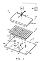
- Figure 1 is a partially schematic perspective view, from above, showing upwardly tapered pegs on a plate-support surface of a microplate apparatus, each peg being configured to engage exterior wall surfaces of four wells of a multi-well plate, when the plate is positioned on the surface, so as to fix the position of all of the plate's wells at known locations on the plate-support surface, thereby permitting an array of acting members to address and operate on the individual wells;
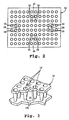
- Figure 2 is a top plan view showing the multi-well plate of Figure 1 placed on the plate-support surface, with the pegs engaging the exterior wall surfaces of respective groupings of wells;
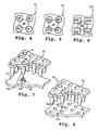
- Figure 3 is a partial perspective view, from above, showing one of the pegs of Figure 2 engaging the exterior wall surfaces of a respective grouping of wells;
- Figure 4 is a partial top view, with portions shown in phantom, of the peg of Figure 3 engaging the exterior wall surfaces of a respective grouping of wells;
- Figure 5 is a partial top view, with portions shown in phantom, showing another embodiment of a peg engaging the exterior wall surfaces of a respective grouping of wells;
- Figure 6 is a partial top view, with portions shown in phantom, showing still a further embodiment of a peg engaging the exterior wall surfaces of a respective grouping of wells;
- Figure 7 is a partial perspective view, from above, showing a projection extending from a plate-support surface, with the projection defining a cavity for engagingly receiving the exterior wall surfaces of a lower region of a well of a multi-well plate;
- Figure 8 is a partial perspective view, from above, showing a plurality of cavities formed in a plate-support surface, with each cavity being configured to engagingly receiving the exterior wall surfaces of a lower region of a respective well of a multi-well plate;
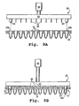
- Figure 9A - 9B are side elevational views, with portions shown in section, of a support with a pair of spaced-apart alignment projections depending therefrom, with the projections being adapted to be engagingly received within respective wells of a multi-well plate, so as to align each of a plurality of acting members, also depending from the support, with a respective well of the plate;
- Figure 10 is a perspective view, from below, showing a support member with a pair of spaced-apart alignment projections and ninety four acting members depending therefrom, collectively forming an 8 x 12 array, poised over a 96-well plate;
- Figure 11 is a perspective view, from below, showing a support member with a four alignment projections and a linear array of acting members, poised over a multi-well plate; and
- Figure 12 is a partial perspective view, from above, showing a non-circular projection and a plurality of acting members depending from a support member, poised over a plurality of non-circular wells of a multi-well plate.
-
- The present invention provides an apparatus and method for accurately locating a multi-well plate at a plate-support location, e.g., a work surface or deck, of an automated laboratory machine, such that one or more acting members, such as an array of pipette tips, optical sensors, or other members, can operate on the individual wells. Features of interest of the plate, such as one or more wells, are used as the primary locating structures of the plate for aligning the entire array of wells with respect to the machine. In preferred embodiments, for example, the interior and/or exterior surface regions of one or more wells of a multi-well plate can be engaged by locating structure of a machine.
- An exemplary microplate apparatus, indicated generally by the
reference numeral 10, is depicted in Figure 1. In overview,apparatus 10 includes a plate (also referred to as a tray), denoted as 12, defining an array of sample wells, such as 14, each having exterior wall surfaces 14a. A plate-handling machine includes (i) a plate-support region, such assurface 16, upon whichplate 12 can be placed, and (ii) a movable sample-handling or reading device, shown generally at 20, having an array of acting members 46 (e.g., reagent-transfer pins), for operating on individual wells in the plate. Locator structure is provided on plate-support surface 16 for quickly and accurately locatingplate 12 thereon. In this embodiment, a plurality ofprojections 24 define the locator structure, with each projection being configured as an upwardly tapered cone or peg adapted to engage the exterior wall surfaces 14a of a respective grouping of four adjacent wells ofplate 12, when the plate is positioned on the surface (Figure 2), so as to fix the position of all of the plate's wells at known locations with respect to defined coordinates, as at 26a-26e, on the plate-support surface. Once the position of each well has been fixed, a control unit (C.U.) 28 can effect movement of the sample-handling or readingdevice 20, via any suitable moving means, relative to one or more ofcoordinates 26a-26e, so that individual acting members of the device can address and operate on respective wells of the plate. - The structure and operation of the present invention will now be described in greater detail.
- Figures 3 and 4 show one upwardly
tapered peg 24, from the embodiment of Figures 1 - 2, mated with regions of the exterior wall surfaces 14a of a group of four downwardly taperedwells 14 ofmicroplate 12. The exterior wall surfaces 14a of the four wells, along a region central to the group, define an upwardly tapered recess or cavity in which the upwardly tapered peg is received. Preferably, the peg and the wells abut along complementary shaped regions to provide a snug fit. By utilizing at least two such pegs, mated with respective groups of wells of the plate, the plate is effectively fixed or locked in place as it rests on the work surface. That is, the plate is prohibited from shifting side-to-side (lateral shifting) to any significant degree across the surface. Moreover, the plate is fixed against downward (vertical) movement, relative to the surface, by (i) permitting the well bottoms to abut the work surface and/or (ii) permitting the top region of the peg to abut the lower surface of the plate. Once the wells have been operated on (as bydevice 20 of Figure 1), the plate can be readily lifted from the work surface. - As illustrated in Figure 1, each peg 24 can include a reduced-diameter, generally cylindrical or rod-like insertion portion, as at 24a, configured to fit snugly within a respective bore or socket, such as 16a, provided in
surface 16. The pegs can be held in place within the bores by any suitable means, e.g., frictional engagement, snap-fitting techniques, adhesives, fasteners, welds, etc. In one preferred embodiment, between about 8 - 14 bores (e.g., 12) are provided in the plate-support surface. All of the bores, in this embodiment, are formed with substantially the same diameter and depth for receiving pegs having lower regions (e.g., likeregion 24a in Figure 1) of a given size. Two or more groups or sets of pegs are provided, with the members of each group being of a selected, uniform size. Other than at their lower regions (i.e., the portions adapted to fit within a bore), the peg size differs between groups. This arrangement is useful for accommodating a variety of plate types/styles. For example, a user can determine (i) which group contains pegs best suited for use with a particular type of plate to be placed on the support surface (e.g., an 8 x 12 well array), and (ii) which bores on the plate support surface should receive pegs from the selected group. A peg from the selected group can then be placed in each of the chosen bores. Should the user later desire to place a different type of plate on the surface (e.g., a 16 x 24 well array), a new, appropriate selection and placement of pegs can be made. - The pegs can be arranged in any suitable, desired pattern on the plate-support surface. In one embodiment, for example, several pegs are clustered along a central region of the plate-support surface. In another embodiment, several pegs are disposed at respective points along the perimeter of the plate-support surface. In yet a further embodiment, the pegs are distributed across the plate-support surface.
- The plate-
support surface 16 andlocator structures 24 are constructed to maintain a plate placed thereon, such as 12, in a designated location for a desired length of time, even under moderate stress or pressure tending to shift or otherwise laterally displace the plate from such location, e.g., due to engagement with acting members ofdevice 20, or vibratory motions caused by operation of the machine. To this end, each of these components is preferably formed of a substantially rigid material that resists bending, warping or other physical deformation under moderate pressure, although the material may be somewhat elastic. For example, in one embodiment, the plate support surface is constructed of a suitable metal or metal alloy, such as stainless steel; and the locator structure (e.g., each peg 24) is injection molded of a sturdy plastic material, such as an acrylic, polycarbonate, polypropylene, polysulfone, or the like. - Preferably, movement of the sample-handling or reading device, relative to the plate, takes place in a substantially automated fashion, e.g., using any suitable moving means; although the invention can be used with manual and/or hybrid arrangements (see, e.g., U.S. Patent No. 3,568,735). In the embodiment of Figure 1,
device 20 is adapted for movement in three dimensions by way of an automated x,y,z-positioning assembly, indicated schematically at 30, under the direction of C.U. 28. The performance envelope ofpositioning assembly 30 permits movement ofdevice 20 toward, away from, and/or across (over)surface 16, as desired.Control unit 28 can be programmed, by conventional techniques, to move thedevice 20 to a specific location relative to one or more of the defined coordinates (26a-26e) on the surface. Alternatively, positioningassembly 30 can be provided with a conventional vision system (not shown), e.g., one or more cameras or other sensing means, operatively connected to the control unit for locating coordinates on the surface. A variety of vision systems for locating coordinate marks on a work surface are known (see, e.g., U.S. Patent No. 5,096,353, and suitable systems for use herein can readily be chosen by those skilled in the art. - In one embodiment, positioning
assembly 30 includes a z-motion actuator coupled to an x,y-shifting assembly. The z-motion actuator, in this embodiment, is operatively connected todevice 20 for moving it along the z direction, toward and away from a raised position. The z-motion actuator can be, for example, a hydraulic, pneumatic, or motor-driven actuator. Several particular assemblies which can be adapted for use herein as the z-motion actuator are disclosed, for example, in U.S. Patent Nos. 3,164,304; 3,329,964; 3,334,354; 5,306,510; 5,443,791; 5,525,515; 5,551,487; 5,601,980; and 5,807,522. The x,y-shifting assembly, to which the z-motion actuator is coupled, is adapted to move the z-motion actuator linearly or in an x-y plane to locate the actuator at a selected location over the plate-support surface. Exemplary automated devices useful for x,y shifting include, for example, robots with electronically controlled linked or crossed movable arms, such as a SCARA, gantry and Cartesian robots. One embodiment employs a motorized x,y-carriage or rail arrangement. In another embodiment, an arm which supports the z-motion actuator is threadedly mounted on a worm screw that can be driven (rotated) in a desired direction by a stepper motor, as directed by the control unit. It is understood, of course, that any other robotic mechanism could be used in accordance with the present invention so long as it can accomplish substantially the same purposes and secure substantially the same result. Several exemplary x,y-shifting assemblies which can be readily adapted for use herein are disclosed, for example, in U.S. Patent Nos. 5,443,791; 5,551,487; 5,306,510; and 5,587,522. - In the above-described embodiments, the plate-support surface of the plate-handling machine remains substantially stationary as the sample-handling or reading device is moved relative thereto. Movement of the sample-handling or reading device, however, is not critical to the invention. What is required is that the position of the sample-handling or reading device be controllable with respect to defined coordinates on the plate-support surface. Providing for movement of the sample-handling or reading device is merely one way of achieving this objective. It will be appreciated that, instead of moving the sample-handling or reading device, or in addition thereto, the plate-support surface can be adapted for movement. Any such arrangements are within the scope of the present invention.
- As previously mentioned, Figure 1 shows
device 20 as an 8 x 12 array of reagent-transfer pins depending from the lower side of a generally planar support, with each pin being adapted to pick up a selected reagent from a respective well and to transfer the reagent to a selected substrate. It should be noted, however, that the invention is not limited to use with such a device. Rather, the device can be of any type, and the nature of the particular device employed will generally be determined by the application at hand. Exemplary devices useful for the transfer of liquid reagents include arrays of pipettes, quills, capillary tubes, syringes, jetting devices (e.g., "sip and spit" devices), etc. Exemplary devices useful for transferring solid or semi-solid reagents, such as micro-beads, include electrostatic and/or magnetic pins or rods, as well as vacuum capillary tubes, and the like. Instead of, or in addition to, using reagent transfer-type devices, the device array can include one or more sensors and/or readers. - From the foregoing, it will now be appreciated that a wide variety of commercially available robotic workstations can be readily adapted for practicing the invention. In particularly suitable workstations, (i) the position of one or more pipette tips, sensors, or other acting members, can be controlled with respect to selected points in space over a plate-support surface (preferably within about 0.2 - 0.3 mm repeatability), and (ii) the locator structure described herein can be accommodated either natively, or by modification/retro-fit. Commercially available workstations and robotic assemblies, contemplated for use with the present invention, include, for example: the TOMTEC QUADRA96 or QUADRA384 Series of Automatic Pipetters, and/or the TECAN GENESIS Series of Robotic Sample Processors (RSP's). Other commercially available robotic assemblies, suitable for use herein, are described, for example, in U.S. Patent No. 5,366,896.
- Additional details pertaining to the locator structure will now be described.
- Where projections having a substantially circular horizontal cross-section are employed, as shown in Figures 1 through 4, the locator structure will typically include more than one such projection in order to prevent pivotal movement of the plate on the surface. Thus, at least two such projections (e.g., four, as shown in Figures 1 and 2) are preferably used to fix the position of
plate 12 onsurface 16. It should be appreciated that a projection need not engage each and every well of a multi-well plate in this embodiment, nor most of the wells. In this regard, it is preferred that the locator structure includes no more than one projection for every four to six wells, or so, of the plate. The embodiment of Figures 1 - 2, for example, provides only one projection for every 24 wells of the plate (i.e., four projections for a 96-well plate). - Where projections having a non-circular horizontal cross-section are used, on the other hand, a single projection can be configured to effectively fix the plate on the support surface without the need for additional projections. For example, one embodiment contemplates the use of a projection, similar to the
projections 24 of Figure 1, but having a non-circular horizontal cross-section (e.g., square, rectangular, or other non-circular shape). In the exemplary arrangement of Figure 5, a projection 124 having a generally square horizontal cross-section with inwardly rounded corners is adapted to fit into a complementary shaped recess defined by exterior surface regions of fourwells 14 ofplate 12. Another exemplary arrangement is shown in Figure 6. Here, aprojection 224 having a generally cross-shaped horizontal sectional profile is adapted to fit into a complementary shaped recess defined by exterior surface regions of a group of four adjacent square-shapedwells 114 of aplate 112. In each such arrangement, the fit of the projection within the recess is effective to prohibit pivotal movement of the plate thereabout, as well as lateral shifting. Thus, in these embodiments, no more than a single projection is required to quickly and accurately fix the position of all of the plate's wells on the support surface. Of course, more projections can be utilized, if desired. - In another embodiment, each projection itself defines a cavity that opens away from the plate support surface and in which the lower region of a respective well can be received. For example, Figure 7 shows a
projection 324 with anaxial bore 40 extending downwardly from its top region, defining a cavity for engagingly receiving the lower region of the exterior wall surfaces 14a of arespective well 14. Where the cavities and wells are generally circular in horizontal cross-section, as in Figure 7, at least two (e.g., four) such projections/cavities are preferably provided. Where the wells and cavities have a non-circular cross-section, on the other hand, one such cavity can be sufficient to fix the position of a plate. For example, a cavity and a mating well can be shaped as a triangle, square, rectangle, or other multi-sided shape; or as an oval, oblong or other rounded, but non-circular, shape. If desired, a plurality of such non-circular cavities (e.g., 2, 4 or 6) can be employed. Irrespective of each cavity's cross-sectional profile, the interior surface regions of each cavity are preferably configured to complement the exterior surface regions the wells. - In a related embodiment, the locator structure includes one or more cavities defined by the plate-support surface itself. For example, one or more cavities (e.g., holes, bores, or the like), such as at 140 in Figure 8, can be formed in the plate-support surface, with each cavity being configured to engagingly receive a lower region of the exterior wall surfaces 14a of a
respective well 14. - In another embodiment, the locator structure is associated with the structure supporting the acting members (e.g., pipettes, optical readers, etc.) of a machine. For example, one or more downwardly extending projections can depend from an acting-member support, along with the acting members of a machine. Introduction of the projections into some of the wells of a multi-well plate serves to align the acting members with the plate's other wells. Preferably, the projections and the interior wall surfaces of the wells have complementary shaped regions. By this construction, when the plate is positioned on the plate-support surface, the complementary shaped regions can closely fit in abutment with one another.
- In an exemplary arrangement of this type, illustrated in Figures 9A - 9B, a sample-handling or reading
device 20 includes asupport portion 42 operably connected to an x,y,z-positioning assembly, shown in part at 30. The locator structure, in this embodiment, includes a pair of elongate projections 44 (e.g., each in the nature of a pin, cone, rod, or the like) disposed in spaced relation alongsupport 42. In addition to the projections, any array of acting members, such as 46, also depend from the support. As the support is lowered from a position above plate 12 (Figure 9A) to a position whereat eachprojection 44 becomes seated within a respective well 14 (Figure 9B), proper alignment of each acting member with a respective well is ensured. As best seen in Figure 9B, the circumferential regions of each projection fit snugly against the interior wall surfaces 14b of a respective well. Each projection is preferably provided with a tapered lower region to assist in bringing the plate into alignment as the support is lowered. - Any reasonable number of projections can depend from the support, as well as any number of acting members. Several exemplary arrangements are shown in Figures 10 - 12. Figure 10, for example, shows a
movable support 142 having twoprojections 44 and ninety four actingmembers 46. Together, theprojections 44 and actingmembers 46 define an 8 x 12 array, with the projections disposed at diagonally opposed comer regions of the array. Preferably, the array is configured to be alignable with the wells of a standard 96-well plate 12. Figure 11 shows twelve actingmembers 46 disposed at respective positions along amovable support 242 so as to define a linear array. Similar to the previous arrangement, the acting members are spaced about 9 mm center-to-center, to be alignable with 12-well rows of a standard 96-well plate 12. Aprojection 44 is disposed at each comer of the support, for assisting in such alignment. The alignment can be readily effected by inserting any two or more of the projections into respective wells of the plate. Figure 12 shows amovable support 342 with a single, non-circular (square)projection 144 depending therefrom, as well as an array of actingmembers 46.Projection 144 is configured to fit snugly within a well 114 ofplate 112. Notably, the well has a non-circular horizontal cross-section substantially like that of the projection. While only one projection is shown in Figure 12, it should be appreciated that additional projections can be utilized, if desired. - In general, it should be appreciated that the locator structure of the present invention can be configured with any reasonable shape, depending upon the specific shape(s) of the mating feature on the plate.
- Any of the embodiments taught herein can further include a biasing assembly operable, with a multi-well plate positioned on the plate-support surface, to urge the locator structure against the wall surfaces of the wells. This can be useful to encourage a close fit between the locator structure and such plate features. With regard to the force applied, one embodiment contemplates a delta of approximately 20.7 KPa (3 psi). For a 7.62 cm (3") x 12.7 cm (5") plate, for example, about 20.4 Kg (45 lbs) total force is contemplated. In one embodiment, particularly useful with the arrangements of Figures 1 - 8, the biasing assembly includes a vacuum source and a flow line for communicating the vacuum source with a lower side of a plate, with the plate positioned on the plate-support surface. The vacuum source, in this embodiment, is operable to draw the plate toward the plate-support surface. Other embodiments contemplate, for example, biasing assemblies that are pneumatic, hydraulic, motorized, and/or spring-loaded. In one embodiment, a z-motion actuator acts as a biasing assembly for pressing the plate toward the plate-support surface.
Positioningassembly 30, of Figures 9A - 9B, for example, can be used to press themovable support 42, from which thelocator structure 44 and actingmembers 46 depend, toward the plate-support surface (upon which the plate sits), with theplate 12 interposed therebetween. - One embodiment contemplates, in addition to the previously described locator structure, one or more walls or bumpers (not shown) disposed along the perimeter of the plate-support surface. Such additional structure is preferably configured to engage the peripheral edges or sidewalls of the plate as the plate is initially being placed on the work surface, thereby effecting a gross alignment of the plate with respect to the work surface. Such gross alignment can be useful for quickly positioning particular groupings of wells, e.g., those positioned about the crosses shown on the upper surface of
plate 12 in Figure 1, over respective pegs disposed on the plate, as indicated by the drop-down dotted lines. Once grossly aligned in this fashion, the wells are then finely aligned as the exterior wall surfaces of the wells engage the pegs, as previously described. - It is noted that the present invention can be readily adapted to accommodate microtiter plates of virtually any size and having wells disposed in any layout. The particular plates used will, of course, be largely determined by the laboratory machine, or machines, and the nature of the assays (e.g., types of reagents) at hand. Although the illustrated embodiments show arrangements configured in accordance with the popular 96-well format, the invention also contemplates any other reasonable number of wells (e.g., 12, 24, 48, 384, etc.) disposed in any suitable configuration.
- It will be appreciated that the present invention can be used for the precise and accurate location of reaction plates on a wide variety of work surfaces, instruments and robotic manipulators. Among these include, for example, plate-handling robots, automatic pipetters, nucleic acid (e.g., RNA or DNA) sequencers, processor work surfaces, detector stages, polymerase chain reaction (PCR) thermal cyclers, etc. In one embodiment, the invention is used with a 384-well pipettor and PE Biosystems 3700.
- It will further be appreciated that the present invention offers many advantages over the known positioning techniques. For example, the location of the reaction plates is as precise as the features of interest. Further, reaction plates made from soft or flexible material can be easily handled and accurately positioned. It will be appreciated that the present invention is adaptable to a wide variety of laboratory apparatuses, without loss of precision. Advantageously, the present invention does not require modification to existing or available reaction plates, nor attachment of any adapter(s).
Claims (25)
- A microplate apparatus (10) including (i) a microtiter plate (12, 112) defining an array of sample wells (14, 114), each having exterior wall surfaces (14a), (ii) a plate-handling machine having a plate-support surface (16) and a sample-handling or reading device (20) which operates on individual wells (14, 114) in the plate (12, 112), and (iii) a control unit (28) for controlling the position of the device (20) with respect to defined coordinates on the plate-support surface (16); characterised in that:the apparatus comprises a locator structure disposed on the plate-support surface (16) for engaging such exterior wall surfaces (14a) of one or more wells (14, 114), when the plate (12, 112) is positioned on the plate-support surface (16), so as to fix the position of each well (14, 114) at a known location with respect to said defined coordinates.
- The apparatus of claim 1, wherein said locator structure comprises at least one projection (24, 124, 224, 324) extending from the plate-support surface (16).
- The apparatus of claim 1, wherein said locator structure comprises two or more projections (24, 124, 224, 324) extending from the plate-support surface (16).
- The apparatus of claim 2 or claim 3, wherein one or more of said projections (24, 124, 224, 324) and the exterior wall surfaces (14a) of one or more wells (14, 114) have complementary shaped regions, with said engaging taking place between such complementary shaped regions when the plate (12, 112) is positioned on the plate-support surface (16).
- The apparatus of claim 4, wherein one or more of said projections (24, 124, 224, 324) tapers on progressing toward their upper regions and one or more wells (14, 114) taper on progressing toward their lower regions, with the exterior wall (14a) surfaces of such tapered wells defining one or more tapered recesses, each adapted to receive one of said projections (24, 124, 224, 324).
- The apparatus of claim 4, wherein each projection (24, 124, 224, 324) defines a central cavity (140) that opens away from said plate-support surface (16); said cavity (140) being configured to receive a lower region of the exterior wall surfaces (14a) of a well (14, 114).
- The apparatus of any one of claims 1 to 6, wherein said locator structure includes no more than one of said projections (24, 124, 224, 324) for every four wells (14, 114) of the well array.
- The apparatus of any one of claims 1 to 6, wherein said locator structure includes no more than one of said projections (24, 124, 224, 324) for every six wells (14, 114) of the well array.
- The apparatus of any preceding claim, further comprising a biasing assembly operable, with such plate (12, 112) positioned on the plate-support surface (16), to urge such exterior wall surfaces (14a) and said locator structure together.
- The apparatus of claim 9, wherein said biasing assembly includes a vacuum source and a flow line communicating said vacuum source with a lower side of such plate (12, 112), with the plate (12 112) positioned on the plate-support surface (16); said vacuum source being operable to draw the plate (12, 112) against the plate-support surface (16).
- The apparatus of any preceding claim, further comprising a movable support (42), to which said device is attached; said moveable support (42) adapted to transport said device toward and away from a position whereat said device can address and operate on individual wells (14, 114) fixed at said known locations.
- The apparatus of any preceding claim, further comprising a positioning assembly (30) adapted for communication with the control unit (28), and operably connected to the plate-support surface (16); said positioning assembly (30) being operable, under direction of the control unit (28), to move the plate-support surface (16) toward and away from a position whereat said sample-handling or reading device (20) can operate on individual wells (14, 114) fixed at said known locations.
- The apparatus of any preceding claim, wherein said device includes a plurality of sample-handling or reading members (20) disposed in an array that is alignable with at least a portion of the well array, with the wells (14, 114) fixed at said known location.
- A microplate apparatus (10) including (i) a microtiter plate (12, 112) defining an array of sample wells (14, 14a), each having exterior wall surfaces (14a), (ii) a plate-handling machine having a plate-support surface (16) and a sample-handling or reading device (20) which operates on individual wells (14, 114) in the plate (12, 112), and (iii) a control unit (28) for controlling the position of the device (20) with respect to defined coordinates on the plate-support surface (16); characterised in that:the apparatus comprises a locator structure defined by the plate-support surface (16), said locator structure being configured to engagingly receive a region of the exterior wall surfaces (14a) of at least one of said wells (14, 114), when the plate (12, 112) is positioned on the plate-support surface (16), so as to fix the position of each well (14, 114) at a known location with respect to said defined coordinates.
- The apparatus of claim 14, wherein said locator structure is configured to engagingly receive regions of the exterior wall surfaces (14a) of at least two of said wells (14, 114).
- The apparatus of claim 15, wherein said locator structure comprises two or more cavities (140) defined by said plate-support surface (16), each cavity (140) being configured to receive a lower region of the exterior wall surfaces (14a) of a respective one of said wells (14, 114).
- The apparatus of claim 14, wherein said locator structure comprises a cavity (140) defined by said plate-support surface (16).
- The apparatus of claim 17, for use with a microtiter plate (12, 112) having wells (114) with a non-circular horizontal cross-sectional profile, wherein said cavity (140) has a non-circular horizontal cross-sectional profile corresponding to that of such wells (114).
- The apparatus of any one of claims 14 to 19, further comprising a biasing assembly operable, with such plate (12, 112) positioned on the plate-support surface (16), to urge such exterior wall surfaces (14a) and said locator structure together.
- A microplate apparatus (10) including (i) a microtiter plate (12, 112) defining an array of sample wells (14, 114), each having interior wall surfaces (14b), (ii) a plate-handling machine having a plate-support surface (16) and an acting-member support (42, 142, 242, 342) with one or more sample-handling or reading members (20) disposed therealong, each member (20) being adapted to operate on an individual well (14, 114) in the plate (12, 112), and (iii) a control unit (28) for controlling the position of the acting-member support (46) with respect to defined coordinates on the plate-support surface (16); characterised in that:the apparatus comprises a locator structure depending from said acting-member support (42, 142, 242, 342) for engaging such interior wall surfaces (14b) of one or more wells (14, 114), when introduced therein, so as to fix the position of one or more of the other wells (14, 114) in alignment with said member(s) (20).
- The apparatus of claim 20, wherein said locator structure and such interior wall surfaces (14b) have complementary shaped regions, with said engaging taking place between such regions when the locator structure is inserted into one or more wells (14b).
- The apparatus of claim 21, wherein said locator structure includes two or more elongate projections (44, 144) disposed in spaced relation along the acting-member support (42, 142, 242, 342).
- The apparatus of any one of claims 20 to 22, wherein the plate-handling machine includes a plurality of sample-handling or reading members (20); and further wherein such members (20) and said locator structure collectively define an array that is alignable with at least a portion of the array of wells (14, 114).
- The apparatus of any one of claims 20 to 23, further comprising a biasing assembly operable, with the locator structure inserted into one or more wells (14, 114), to urge such interior wall surfaces (14b) and said locator structure together.
- The apparatus of claim 24, wherein said biasing assembly presses said acting-member support (42, 142, 242, 342) toward the plate-support surface (16), with the plate (12, 112) interposed therebetween.
Applications Claiming Priority (3)
| Application Number | Priority Date | Filing Date | Title |
|---|---|---|---|
| US32131199A | 1999-05-27 | 1999-05-27 | |
| US321311 | 1999-05-27 | ||
| PCT/US2000/014475 WO2000072969A1 (en) | 1999-05-27 | 2000-05-25 | Apparatus and method for the precise location of reaction plates |
Publications (2)
| Publication Number | Publication Date |
|---|---|
| EP1183103A1 EP1183103A1 (en) | 2002-03-06 |
| EP1183103B1 true EP1183103B1 (en) | 2003-02-12 |
Family
ID=23250082
Family Applications (1)
| Application Number | Title | Priority Date | Filing Date |
|---|---|---|---|
| EP00936314A Expired - Lifetime EP1183103B1 (en) | 1999-05-27 | 2000-05-25 | Apparatus and method for the precise location of reaction plates |
Country Status (8)
| Country | Link |
|---|---|
| US (2) | US6878341B2 (en) |
| EP (1) | EP1183103B1 (en) |
| JP (1) | JP2003500673A (en) |
| AT (1) | ATE232418T1 (en) |
| AU (1) | AU754172B2 (en) |
| CA (1) | CA2373741C (en) |
| DE (1) | DE60001406T2 (en) |
| WO (1) | WO2000072969A1 (en) |
Families Citing this family (30)
| Publication number | Priority date | Publication date | Assignee | Title |
|---|---|---|---|---|
| US20030054543A1 (en) * | 1997-06-16 | 2003-03-20 | Lafferty William Michael | Device for moving a selected station of a holding plate to a predetermined location for interaction with a probe |
| EP1434055B1 (en) * | 1999-02-16 | 2006-09-27 | Applera Corporation | Bead dispensing system |
| EP1200841A1 (en) * | 1999-08-13 | 2002-05-02 | Cartesian Technologies, Inc. | Apparatus for liquid sample handling |
| US20040018615A1 (en) * | 2000-08-02 | 2004-01-29 | Garyantes Tina K. | Virtual wells for use in high throughput screening assays |
| EP1323465A1 (en) * | 2001-12-31 | 2003-07-02 | Corning Incorporated | Flexible high density array print head with systems and methods for aligning pin plate, reservoir and substrate with respect to each other |
| CN103399162B (en) * | 2002-05-17 | 2016-04-27 | 贝克顿·迪金森公司 | For separating of, amplify and detect the automated system of target nucleic acid sequence |
| US7128878B2 (en) * | 2002-10-04 | 2006-10-31 | Becton, Dickinson And Company | Multiwell plate |
| AU2003302264A1 (en) | 2002-12-20 | 2004-09-09 | Biotrove, Inc. | Assay apparatus and method using microfluidic arrays |
| US20050112783A1 (en) * | 2003-08-04 | 2005-05-26 | Irm, Llc | Non-pressure based fluid transfer in assay detection systems and related methods |
| US8349279B2 (en) * | 2005-07-22 | 2013-01-08 | Tsubakimoto Chain Co. | Samples storage system for pharmaceutical development |
| US7560075B2 (en) * | 2006-01-24 | 2009-07-14 | Bio-Rad Laboratories, Inc. | Planar registration of multi-well plate from well side |
| US7876935B2 (en) * | 2006-01-30 | 2011-01-25 | Protedyne Corporation | Sample processing apparatus with a vision system |
| JP2007248361A (en) * | 2006-03-17 | 2007-09-27 | Toshiba Corp | Antibody chip, antigen measuring device, and liquid ejection method |
| IES20060872A2 (en) * | 2006-12-05 | 2008-09-17 | Trinity Res Ltd | A well plate for holding a sample during analysis and a method for analysing a sample |
| WO2009067103A1 (en) | 2007-11-20 | 2009-05-28 | Hewlett-Packard Development Company, L.P. | Liquid handling device |
| EP2263802A1 (en) * | 2009-05-25 | 2010-12-22 | F. Hoffmann-La Roche AG | System and method for dispensing fluids |
| EP2338600B1 (en) * | 2009-12-10 | 2017-07-12 | F. Hoffmann-La Roche AG | Process head positioning |
| JP6049235B2 (en) * | 2009-12-10 | 2016-12-21 | エフ.ホフマン−ラ ロシュ アーゲーF. Hoffmann−La Roche Aktiengesellschaft | Combination tip rack |
| CN102279260A (en) * | 2010-06-12 | 2011-12-14 | 北京众合百克科学仪器技术有限公司 | Clamping device for clamping ELISA (Enzyme-Linked Immuno Sorbent Assay) plate in chemoluminescence immunoassay instrument |
| CN102752954A (en) * | 2011-04-22 | 2012-10-24 | 鸿富锦精密工业(深圳)有限公司 | Flexible printed circuit board and electronic device using flexible printed circuit board |
| KR101320246B1 (en) * | 2012-01-17 | 2013-10-23 | 삼성전기주식회사 | Bio-chip module and device for measuring bio-chip |
| US9804181B2 (en) | 2013-01-15 | 2017-10-31 | Siemens Healthcare Diagnostics Inc. | Automation tube positioning methodology |
| CN103884856B (en) * | 2014-04-01 | 2015-06-10 | 重庆科斯迈生物科技有限公司 | Cup strip conveying system of chemiluminescence immunoassay analyzer |
| KR101714156B1 (en) * | 2015-06-08 | 2017-03-08 | 현대자동차주식회사 | Inspection apparatus |
| JP2018012791A (en) * | 2016-07-21 | 2018-01-25 | 日立化成株式会社 | Thermosetting resin composition, prepreg, laminate and printed wiring board |
| WO2019055033A1 (en) * | 2017-09-15 | 2019-03-21 | Hewlett-Packard Development Company, L.P. | Dna concentrate dispensing |
| US20210008547A1 (en) * | 2017-09-15 | 2021-01-14 | Hewlett-Packard Development Company, L.P. | Dna concentrate dispensing |
| WO2019059936A1 (en) * | 2017-09-23 | 2019-03-28 | Hewlett-Packard Development Company, L.P. | Electroporation |
| USD905267S1 (en) * | 2019-03-27 | 2020-12-15 | Avidien Technologies, Inc. | Pipette tip adapter |
| CN115122254B (en) * | 2022-06-28 | 2024-01-09 | 苏州维嘉科技股份有限公司 | Vacuum adsorption table, PCB product fixing method and PCB product processing equipment |
Family Cites Families (46)
| Publication number | Priority date | Publication date | Assignee | Title |
|---|---|---|---|---|
| US3164304A (en) | 1961-05-08 | 1965-01-05 | Standard Thomson Corp | Liquid dispensing apparatus for small quantities |
| US3329964A (en) | 1965-06-24 | 1967-07-04 | Xerox Corp | Facsimile recording apparatus |
| US3334354A (en) | 1966-03-17 | 1967-08-01 | Xerox Corp | Dotting ink recorder |
| US3568735A (en) * | 1968-06-26 | 1971-03-09 | Cooke Eng Co | Laboratory microtitration dispensing apparatus |
| US4154795A (en) | 1976-07-23 | 1979-05-15 | Dynatech Holdings Limited | Microtest plates |
| US4299493A (en) | 1979-12-10 | 1981-11-10 | Harrison Venton R | Auto-optical centering device for photometers |
| US4596037A (en) | 1984-03-09 | 1986-06-17 | International Business Machines Corporation | Video measuring system for defining location orthogonally |
| US4952518A (en) | 1984-10-01 | 1990-08-28 | Cetus Corporation | Automated assay machine and assay tray |
| FI853895A0 (en) | 1985-10-07 | 1985-10-07 | Labsystems Oy | IMMUNOLOGISKT BESTAEMNINGSSYSTEM. |
| US5605160A (en) | 1986-04-18 | 1997-02-25 | Fishman; Henry | Allergy testing apparatus with variably spaced test testing sites |
| US4948564A (en) | 1986-10-28 | 1990-08-14 | Costar Corporation | Multi-well filter strip and composite assemblies |
| US4895706A (en) | 1986-10-28 | 1990-01-23 | Costar Corporation | Multi-well filter strip and composite assemblies |
| US4988618A (en) | 1987-11-16 | 1991-01-29 | Gene-Trak Systems | Magnetic separation device and methods for use in heterogeneous assays |
| US5306510A (en) | 1988-01-14 | 1994-04-26 | Cyberlab, Inc. | Automated pipetting system |
| CN1013426B (en) * | 1988-02-22 | 1991-08-07 | 东芝株式会社 | Deodorizing device in refrigerator |
| US4974244A (en) | 1988-08-04 | 1990-11-27 | Angelo M. Torrisi | Sample positioning method and system for X-ray spectroscopic analysis |
| US5355304A (en) | 1990-01-30 | 1994-10-11 | Demoranville Victoria E | Clinical laboratory work-flow system which semi-automates validated immunoassay and electrophoresis protocols |
| WO1991016675A1 (en) | 1990-04-06 | 1991-10-31 | Applied Biosystems, Inc. | Automated molecular biology laboratory |
| US5096353A (en) | 1990-07-27 | 1992-03-17 | Motorola, Inc. | Vision system for a robotic station |
| KR100236506B1 (en) | 1990-11-29 | 2000-01-15 | 퍼킨-엘머시터스인스트루먼츠 | Apparatus for polymerase chain reaction |
| US5112574A (en) | 1991-04-26 | 1992-05-12 | Imanigation, Ltd. | Multititer stopper array for multititer plate or tray |
| US5366896A (en) | 1991-07-30 | 1994-11-22 | University Of Virginia Alumni Patents Foundation | Robotically operated laboratory system |
| US5205989A (en) | 1991-09-18 | 1993-04-27 | Minnesota Mining And Manufacturing Company | Multi-well filtration apparatus |
| US5154343A (en) * | 1992-01-21 | 1992-10-13 | Packaging Corporation Of America | Flip-top recloseable carton with positive closure arrangement |
| US5326533A (en) | 1992-11-04 | 1994-07-05 | Millipore Corporation | Multiwell test apparatus |
| US5525515A (en) | 1993-02-03 | 1996-06-11 | Blattner; Frederick R. | Process of handling liquids in an automated liquid handling apparatus |
| US5417922A (en) | 1993-05-14 | 1995-05-23 | Board Of Regents - University Of Nebraska | Specimen carrier |
| CH687592A5 (en) | 1993-10-18 | 1997-01-15 | Eidgenoess Munitionsfab Thun | Mehrgefaessanordnung for instrumental analysis. |
| US5540889A (en) | 1994-05-11 | 1996-07-30 | Whitehead Institute For Biomedical Research | Apparatus and method for a highly parallel pipetter |
| US5460783A (en) | 1994-06-14 | 1995-10-24 | Synbiotics Corporation | Apparatus for automatically removing microtiter well-strips from well-strip holders |
| US5807522A (en) | 1994-06-17 | 1998-09-15 | The Board Of Trustees Of The Leland Stanford Junior University | Methods for fabricating microarrays of biological samples |
| US5514343A (en) | 1994-06-22 | 1996-05-07 | Nunc, As | Microtitration system |
| US5601980A (en) | 1994-09-23 | 1997-02-11 | Hewlett-Packard Company | Manufacturing method and apparatus for biological probe arrays using vision-assisted micropipetting |
| US5550033A (en) | 1994-09-26 | 1996-08-27 | Krumdieck; Carlos | Mold plunger and method for embedding tissue samples |
| US5792426A (en) | 1994-10-11 | 1998-08-11 | Schweizerische Eidgenossenschaft Vertreten Durch Das Ac-Laboratorium Spiez Der Gruppe Rustung | Multi-well titerplate for instrumental analysis |
| FR2730315B1 (en) | 1995-02-07 | 1997-03-21 | Abx Sa | DEVICE FOR STIRRING AND TAKING SAMPLES OF BLOOD PRODUCTS FROM TUBES GROUPED INTO CASSETTES |
| US5551487A (en) | 1995-03-10 | 1996-09-03 | Hewlett-Packard Company | Micro-dispenser for preparing assay plates |
| US5534227A (en) * | 1995-06-05 | 1996-07-09 | Becton, Dickinson And Company | Thermoform dish insert |
| US5620894A (en) | 1995-06-16 | 1997-04-15 | Glaxo Wellcome Inc. | Apparatus for automated biological cell harvesting |
| US5587522A (en) | 1995-12-26 | 1996-12-24 | Selby; Theodore W. | Multiple-part and/or supported gas-containing vessel to establish desired heat flux |
| US5858309A (en) | 1996-03-22 | 1999-01-12 | Corning Incorporated | Microplates with UV permeable bottom wells |
| US5800784A (en) | 1996-07-09 | 1998-09-01 | Horn; Marcus J. | Chemical sample treatment system and cassette, and methods for effecting multistep treatment process |
| US5779907A (en) * | 1996-12-06 | 1998-07-14 | Systems Research Laboratories, Inc. | Magnetic microplate separator |
| US5865224A (en) | 1996-12-20 | 1999-02-02 | Life Technologies, Inc. | Method and apparatus for automated dispensing |
| US5985214A (en) * | 1997-05-16 | 1999-11-16 | Aurora Biosciences Corporation | Systems and methods for rapidly identifying useful chemicals in liquid samples |
| US6063579A (en) * | 1998-10-30 | 2000-05-16 | Incyte Pharmaceuticals, Inc. | Alignment mechanism |
-
2000
- 2000-05-25 AU AU51644/00A patent/AU754172B2/en not_active Ceased
- 2000-05-25 JP JP2000621072A patent/JP2003500673A/en active Pending
- 2000-05-25 WO PCT/US2000/014475 patent/WO2000072969A1/en active IP Right Grant
- 2000-05-25 DE DE60001406T patent/DE60001406T2/en not_active Expired - Lifetime
- 2000-05-25 EP EP00936314A patent/EP1183103B1/en not_active Expired - Lifetime
- 2000-05-25 AT AT00936314T patent/ATE232418T1/en not_active IP Right Cessation
- 2000-05-25 CA CA002373741A patent/CA2373741C/en not_active Expired - Fee Related
-
2001
- 2001-12-06 US US10/010,659 patent/US6878341B2/en not_active Expired - Fee Related
-
2005
- 2005-02-28 US US11/069,322 patent/US20050152810A1/en not_active Abandoned
Also Published As
| Publication number | Publication date |
|---|---|
| WO2000072969A1 (en) | 2000-12-07 |
| AU5164400A (en) | 2000-12-18 |
| US20050152810A1 (en) | 2005-07-14 |
| AU754172B2 (en) | 2002-11-07 |
| CA2373741C (en) | 2006-02-07 |
| DE60001406D1 (en) | 2003-03-20 |
| US6878341B2 (en) | 2005-04-12 |
| CA2373741A1 (en) | 2000-12-07 |
| US20020094578A1 (en) | 2002-07-18 |
| ATE232418T1 (en) | 2003-02-15 |
| EP1183103A1 (en) | 2002-03-06 |
| JP2003500673A (en) | 2003-01-07 |
| DE60001406T2 (en) | 2004-01-15 |
Similar Documents
| Publication | Publication Date | Title |
|---|---|---|
| EP1183103B1 (en) | Apparatus and method for the precise location of reaction plates | |
| EP2459313B1 (en) | Means for improved liquid handling in a microplate | |
| US6372185B1 (en) | Liquid chemical distribution method and apparatus | |
| US9126200B2 (en) | Positioning device for a sample carrier | |
| US9579646B2 (en) | Dual tip array dispensing head | |
| US11179716B2 (en) | Metering head, metering device comprising a metering head, and method for metering by means of a metering head | |
| JP2004518121A (en) | Plate locator for precision liquid handler | |
| AU2005271298A1 (en) | Object storage devices, systems, and related methods | |
| US9383379B2 (en) | Sample distribution in a method for isolating analytes in fluid samples in an automated system | |
| US20060188409A1 (en) | Multi-well container positioning devices, systems, computer program products, and methods | |
| WO2002039084A9 (en) | Variable geometry fluid sample loader | |
| WO2004076018A2 (en) | Reagent dispenser and dispensing method | |
| GB2472252A (en) | Microplate holder for inclining a microplate | |
| JP2008518796A (en) | Equipment for joining auxiliary equipment |
Legal Events
| Date | Code | Title | Description |
|---|---|---|---|
| PUAI | Public reference made under article 153(3) epc to a published international application that has entered the european phase |
Free format text: ORIGINAL CODE: 0009012 |
|
| 17P | Request for examination filed |
Effective date: 20011105 |
|
| AK | Designated contracting states |
Kind code of ref document: A1 Designated state(s): AT BE CH CY DE DK ES FI FR GB GR IE IT LI LU MC NL PT SE |
|
| AX | Request for extension of the european patent |
Free format text: AL;LT;LV;MK;RO;SI |
|
| 17Q | First examination report despatched |
Effective date: 20020227 |
|
| GRAG | Despatch of communication of intention to grant |
Free format text: ORIGINAL CODE: EPIDOS AGRA |
|
| GRAG | Despatch of communication of intention to grant |
Free format text: ORIGINAL CODE: EPIDOS AGRA |
|
| GRAH | Despatch of communication of intention to grant a patent |
Free format text: ORIGINAL CODE: EPIDOS IGRA |
|
| GRAH | Despatch of communication of intention to grant a patent |
Free format text: ORIGINAL CODE: EPIDOS IGRA |
|
| GRAA | (expected) grant |
Free format text: ORIGINAL CODE: 0009210 |
|
| AK | Designated contracting states |
Designated state(s): AT BE CH CY DE DK ES FI FR GB GR IE IT LI LU MC NL PT SE |
|
| PG25 | Lapsed in a contracting state [announced via postgrant information from national office to epo] |
Ref country code: AT Free format text: LAPSE BECAUSE OF FAILURE TO SUBMIT A TRANSLATION OF THE DESCRIPTION OR TO PAY THE FEE WITHIN THE PRESCRIBED TIME-LIMIT Effective date: 20030212 Ref country code: BE Free format text: LAPSE BECAUSE OF FAILURE TO SUBMIT A TRANSLATION OF THE DESCRIPTION OR TO PAY THE FEE WITHIN THE PRESCRIBED TIME-LIMIT Effective date: 20030212 Ref country code: FI Free format text: LAPSE BECAUSE OF FAILURE TO SUBMIT A TRANSLATION OF THE DESCRIPTION OR TO PAY THE FEE WITHIN THE PRESCRIBED TIME-LIMIT Effective date: 20030212 Ref country code: GR Free format text: LAPSE BECAUSE OF FAILURE TO SUBMIT A TRANSLATION OF THE DESCRIPTION OR TO PAY THE FEE WITHIN THE PRESCRIBED TIME-LIMIT Effective date: 20030212 |
|
| REG | Reference to a national code |
Ref country code: GB Ref legal event code: FG4D |
|
| REG | Reference to a national code |
Ref country code: CH Ref legal event code: EP |
|
| REF | Corresponds to: |
Ref document number: 60001406 Country of ref document: DE Date of ref document: 20030320 Kind code of ref document: P |
|
| PG25 | Lapsed in a contracting state [announced via postgrant information from national office to epo] |
Ref country code: PT Free format text: LAPSE BECAUSE OF FAILURE TO SUBMIT A TRANSLATION OF THE DESCRIPTION OR TO PAY THE FEE WITHIN THE PRESCRIBED TIME-LIMIT Effective date: 20030512 Ref country code: DK Free format text: LAPSE BECAUSE OF FAILURE TO SUBMIT A TRANSLATION OF THE DESCRIPTION OR TO PAY THE FEE WITHIN THE PRESCRIBED TIME-LIMIT Effective date: 20030512 |
|
| PG25 | Lapsed in a contracting state [announced via postgrant information from national office to epo] |
Ref country code: CY Free format text: LAPSE BECAUSE OF FAILURE TO SUBMIT A TRANSLATION OF THE DESCRIPTION OR TO PAY THE FEE WITHIN THE PRESCRIBED TIME-LIMIT Effective date: 20030525 Ref country code: LU Free format text: LAPSE BECAUSE OF NON-PAYMENT OF DUE FEES Effective date: 20030525 |
|
| PG25 | Lapsed in a contracting state [announced via postgrant information from national office to epo] |
Ref country code: IE Free format text: LAPSE BECAUSE OF NON-PAYMENT OF DUE FEES Effective date: 20030526 |
|
| REG | Reference to a national code |
Ref country code: CH Ref legal event code: NV Representative=s name: ISLER & PEDRAZZINI AG |
|
| PG25 | Lapsed in a contracting state [announced via postgrant information from national office to epo] |
Ref country code: MC Free format text: LAPSE BECAUSE OF NON-PAYMENT OF DUE FEES Effective date: 20030531 |
|
| REG | Reference to a national code |
Ref country code: SE Ref legal event code: TRGR |
|
| LTIE | Lt: invalidation of european patent or patent extension |
Effective date: 20030212 |
|
| PG25 | Lapsed in a contracting state [announced via postgrant information from national office to epo] |
Ref country code: ES Free format text: LAPSE BECAUSE OF FAILURE TO SUBMIT A TRANSLATION OF THE DESCRIPTION OR TO PAY THE FEE WITHIN THE PRESCRIBED TIME-LIMIT Effective date: 20030828 |
|
| ET | Fr: translation filed | ||
| PLBE | No opposition filed within time limit |
Free format text: ORIGINAL CODE: 0009261 |
|
| STAA | Information on the status of an ep patent application or granted ep patent |
Free format text: STATUS: NO OPPOSITION FILED WITHIN TIME LIMIT |
|
| 26N | No opposition filed |
Effective date: 20031113 |
|
| REG | Reference to a national code |
Ref country code: CH Ref legal event code: PUE Owner name: APPLERA CORPORATION Free format text: PE CORPORATION (NY)#850 LINCOLN CENTRE DRIVE#FOSTER CITY, CA 94404 (US) -TRANSFER TO- APPLERA CORPORATION#850 LINCOLN CENTRE DRIVE#FOSTER CITY, CA 94404 (US) |
|
| REG | Reference to a national code |
Ref country code: GB Ref legal event code: 732E |
|
| REG | Reference to a national code |
Ref country code: IE Ref legal event code: MM4A |
|
| REG | Reference to a national code |
Ref country code: FR Ref legal event code: TP |
|
| PGFP | Annual fee paid to national office [announced via postgrant information from national office to epo] |
Ref country code: NL Payment date: 20050429 Year of fee payment: 6 |
|
| PGFP | Annual fee paid to national office [announced via postgrant information from national office to epo] |
Ref country code: FR Payment date: 20050517 Year of fee payment: 6 |
|
| PGFP | Annual fee paid to national office [announced via postgrant information from national office to epo] |
Ref country code: SE Payment date: 20050519 Year of fee payment: 6 |
|
| PGFP | Annual fee paid to national office [announced via postgrant information from national office to epo] |
Ref country code: CH Payment date: 20050520 Year of fee payment: 6 |
|
| PG25 | Lapsed in a contracting state [announced via postgrant information from national office to epo] |
Ref country code: SE Free format text: LAPSE BECAUSE OF NON-PAYMENT OF DUE FEES Effective date: 20060526 |
|
| PG25 | Lapsed in a contracting state [announced via postgrant information from national office to epo] |
Ref country code: LI Free format text: LAPSE BECAUSE OF NON-PAYMENT OF DUE FEES Effective date: 20060531 Ref country code: CH Free format text: LAPSE BECAUSE OF NON-PAYMENT OF DUE FEES Effective date: 20060531 |
|
| PG25 | Lapsed in a contracting state [announced via postgrant information from national office to epo] |
Ref country code: NL Free format text: LAPSE BECAUSE OF NON-PAYMENT OF DUE FEES Effective date: 20061201 |
|
| REG | Reference to a national code |
Ref country code: CH Ref legal event code: PL |
|
| EUG | Se: european patent has lapsed | ||
| NLV4 | Nl: lapsed or anulled due to non-payment of the annual fee |
Effective date: 20061201 |
|
| REG | Reference to a national code |
Ref country code: FR Ref legal event code: ST Effective date: 20070131 |
|
| PG25 | Lapsed in a contracting state [announced via postgrant information from national office to epo] |
Ref country code: FR Free format text: LAPSE BECAUSE OF NON-PAYMENT OF DUE FEES Effective date: 20060531 |
|
| REG | Reference to a national code |
Ref country code: GB Ref legal event code: 732E Free format text: REGISTERED BETWEEN 20090514 AND 20090520 |
|
| REG | Reference to a national code |
Ref country code: GB Ref legal event code: 732E Free format text: REGISTERED BETWEEN 20100121 AND 20100127 |
|
| PGFP | Annual fee paid to national office [announced via postgrant information from national office to epo] |
Ref country code: GB Payment date: 20110525 Year of fee payment: 12 |
|
| PGFP | Annual fee paid to national office [announced via postgrant information from national office to epo] |
Ref country code: DE Payment date: 20110527 Year of fee payment: 12 Ref country code: IT Payment date: 20110525 Year of fee payment: 12 |
|
| GBPC | Gb: european patent ceased through non-payment of renewal fee |
Effective date: 20120525 |
|
| PG25 | Lapsed in a contracting state [announced via postgrant information from national office to epo] |
Ref country code: IT Free format text: LAPSE BECAUSE OF NON-PAYMENT OF DUE FEES Effective date: 20120525 |
|
| REG | Reference to a national code |
Ref country code: DE Ref legal event code: R119 Ref document number: 60001406 Country of ref document: DE Effective date: 20121201 |
|
| PG25 | Lapsed in a contracting state [announced via postgrant information from national office to epo] |
Ref country code: GB Free format text: LAPSE BECAUSE OF NON-PAYMENT OF DUE FEES Effective date: 20120525 |
|
| PG25 | Lapsed in a contracting state [announced via postgrant information from national office to epo] |
Ref country code: DE Free format text: LAPSE BECAUSE OF NON-PAYMENT OF DUE FEES Effective date: 20121201 |