EP1172660A2 - Method and device for fault location in distribution networks - Google Patents
Method and device for fault location in distribution networks Download PDFInfo
- Publication number
- EP1172660A2 EP1172660A2 EP01202430A EP01202430A EP1172660A2 EP 1172660 A2 EP1172660 A2 EP 1172660A2 EP 01202430 A EP01202430 A EP 01202430A EP 01202430 A EP01202430 A EP 01202430A EP 1172660 A2 EP1172660 A2 EP 1172660A2
- Authority
- EP
- European Patent Office
- Prior art keywords
- fault
- impedance
- phase
- calculating
- lines
- Prior art date
- Legal status (The legal status is an assumption and is not a legal conclusion. Google has not performed a legal analysis and makes no representation as to the accuracy of the status listed.)
- Granted
Links
Images


Classifications
-
- G—PHYSICS
- G01—MEASURING; TESTING
- G01R—MEASURING ELECTRIC VARIABLES; MEASURING MAGNETIC VARIABLES
- G01R31/00—Arrangements for testing electric properties; Arrangements for locating electric faults; Arrangements for electrical testing characterised by what is being tested not provided for elsewhere
- G01R31/08—Locating faults in cables, transmission lines, or networks
- G01R31/088—Aspects of digital computing
Definitions
- the present invention relates to a method for location of a fault which has occurred on one of the lines or feeders in a distribution network where the location is performed with the aid of measured values of the common supply voltage of the lines and the currents of the lines after the occurrence of a fault; calculating the equivalent positive-sequence impedance Z f / 1 k and zero-sequence impedance Z f / 0 k of the network in a pre-fault steady state for all M nodes based on knowledge of the configuration and topology of the network, and obtaining, via a superordinate protection system, information about which line has become faulty and which type of fault has occurred.
- the invention also relates to a device for carrying out the method.
- DN distribution networks
- cable or overhead is normally an integral part of superordinate protection systems relating to faults on circuit breakers, contactors, relays etc.
- the faulty line may be determined.
- the word line is used, but in this context it is to be understood that it equally applicable to feeders or cables, and combinations thereof.
- the state of the art as regards fault location in a DN comprises two fundamentally different methods.
- One of the methods is based on the provision of a fault locator on each line, which entails heavy investment costs, and the other method comprises measuring centrally the voltage and the sum current for all the DN lines in the DN station.
- the latter method involves a plurality of problems, which make it difficult to obtain a relatively reliable measure of the distance to the fault:
- the fault-located line may have a plurality of distributed branch points, nodes, where also some branches have parallel loads.
- the starting-point is voltage and current measured at the DN station prior to and after the occurrence of a fault, whereupon the respective positive-sequence components are determined. It is assumed that the data of the line between each node and the load at each node prior to a fault are known.
- a first assumed value of the distance to the fault is determined on the basis of the positive-sequence impedance of the remote end prior to the fault.
- the positive-sequence components of current and voltage at the fault node after the occurrence of the fault are then used for determining the first calculated value of the distance to the fault.
- These two values are compared with each other, and if the difference is greater than a least value set in advance, a new assumption is made as to between which nodes the fault is located, based on the value now calculated.
- This provides a new load model and a second calculated value of the distance to the fault.
- This value is then compared with the first calculated value, which comparison may result in an additional number of iterations until the difference value between two consecutively calculated values lies within the permissible values.
- the method does not permit fault location in case of a three-phase fault.
- determination of the distance to the fault on a faulty line of a Distribution Network may be performed, wherein the method takes into consideration the influences of non-homogenities, branches and loads of the DN. Further the method according to the invention is not dependent of where in the network measurements are being made, i e does not depend on if the currents and voltages of each line or branch are measured separately or if the voltage and sum current for all the lines are measured centrally.
- the principle of distance determination according to the invention is particularly useful for cable networks but may also advantageously be used for overhead line networks.
- the method proposed for this invention overcomes the difficulties discussed above by delivering a method for fault location in distribution networks characterised by the features of claim 1.
- the equivalent positive- ( Z f / 1 k ) and zero-sequence ( Z f / 0 k ) impedance of the network is computed in pre-fault steady-state for all M nodes of the network based on existing topology, loads and feeder parameters.
- the specific fault-loop parameters are calculated depending on the fault-loop type (phase-phase or phase-ground) and the place of measurements (at the supplying transformer or at the faulty feeder).
- the final distance to fault will be chosen when the condition as in (A) is fulfilled.
- the method of calculation of the parameters ( Z 1 f , I p , I pN ) depends on the place of measurement (at the substation or the feeder).
- the present invention it is possible to determine the distance to fault in a very accurate and reliable way. Especially in distribution networks including a plurality of different line or cable sections and with branches and loads along the lines, the present invention takes this into account by utilising fault loop approaches depending on the type of fault and going through the consecutive nodes of the network calculating the residual impedance in order to arrive at a distance value.
- the topology of the network comprising electrical data such as the number of lines, branches, lengths of lines between branches and the respective line impedances and of actual loads on the lines and loads at the lines, are used for steady-state network impedance calculation, and according to the algorithm used in the present invention for distance to fault calculation, one should calculate impedance Z f / 1 k and Z f / 0 k for steady-state condition and parameters Z 1 f , k I , Z 1 N from measurements according to
- the positive sequence loop for phase-to-ground fault is obtained as follows.
- Equation (8) For a feeder including sections with different types of cable coefficient k kN can not be calculated according to equation (8) because, in general, they have different per kilometer zero- and positive sequence parameters.
- Relation (11) is the basis for invented method according to equations (1-3) for phase-to-ground faults.
- the parameters k I and Z 1 N can be calculated from measurements whereas Z f / lk and Z f / 0 k Z f 0 k are actual positive- and zero-sequence impedance of a fault-loop. The last can be obtained from off-line calculation based on network parameters.
- Equation (11) - Z f / 1 k - represents equivalent positive-sequence fault loop impedance seen from the substation.
- equation (11) there is combination of the positive- and zero-sequence measurements available at the substation ( Z 1 N , k I ) and zero-sequence impedance of the network from the substation to the fault point Z f / 0 k .
- the final distance to fault will be chosen when the condition as in (1) is fulfilled.
- phase-to-phase fault loop and phase-to-ground fault loop.
- Representation of the impedance Z f / 1 k in a form as in Fig. 3 provides a possibility to include the fault resistance in a fault-loop as shown in Fig. 4a.
- the residual impedance ⁇ Z f represents the equivalent impedance involved in fault-loop due to the fault resistance R f if the fault occurs at node k or behind them.
- the equivalent scheme for representation of the impedance ⁇ Z f is presented in Fig. 4b.
- the algorithm for distance x calculation is derived as follows:
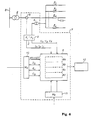
- FIG. 6 An example of a device according to the invention for fault location on one of the lines included in a distribution network is clear from Figure 6 and comprises:
- the fault locator 6 comprises:
- the network data which, via the unit M N , 10, are to be input into the fault locator comprise:
- the network data which, after a fault has occurred, are to be input into the fault locator via the unit M F , 11 comprise
- the information about the type of fault and which line has become faulty is obtained from a superordinate protection and expert system.
- a device according to the invention for fault location on one of the lines included in DN may be designed in a plurality of ways similar to that shown in Figure 6.
- the filters 8 and 9 for filtering measured data for current and voltage and the input units 10 and 11 for network data and fault information may be more or less integrated into the fault locator 6.
- the device also comprises one or more micro computers.
- the micro processor (or processors) comprises a central processing unit CPU performing the steps of the method according to the invention. This is performed with the aid of a dedicated computer program, which is stored in the program memory. It is to be understood that the computer program may also be run on a general purpose industrial computer instead of a specially adapted computer.
- the software includes computer program code elements or software code portions that make the computer perform the method using equations, algorithms, data and calculations previously described.
- a part of the program may be stored in a processor as above, but also in a ROM, RAM, PROM or EPROM chip or similar.
- the program in part or in whole may also be stored on, or in, other suitable computer readable medium such as a magnetic disk, CD-ROM or DVD disk, hard disk, magneto-optical memory storage means, in volatile memory, in flash memory, as firmware, or stored on a data server.
- the method proposed in this invention realises the procedure for the fault location in distribution networks in the following steps:
Landscapes
- Physics & Mathematics (AREA)
- Engineering & Computer Science (AREA)
- Mathematical Physics (AREA)
- Theoretical Computer Science (AREA)
- General Physics & Mathematics (AREA)
- Locating Faults (AREA)
- Emergency Protection Circuit Devices (AREA)
- Examining Or Testing Airtightness (AREA)
Abstract

wherein, upon being fulfilled, the distance to fault is chosen.
Description
- The present invention relates to a method for location of a fault which has occurred on one of the lines or feeders in a distribution network where the location is performed with the aid of measured values of the common supply voltage of the lines and the currents of the lines after the occurrence of a fault; calculating the equivalent positive-sequence impedance Z f / 1k and zero-sequence impedance Z f / 0k of the network in a pre-fault steady state for all M nodes based on knowledge of the configuration and topology of the network, and obtaining, via a superordinate protection system, information about which line has become faulty and which type of fault has occurred. The invention also relates to a device for carrying out the method.
- Fault location in distribution networks (DN), cable or overhead, is normally an integral part of superordinate protection systems relating to faults on circuit breakers, contactors, relays etc. With the aid of various protection, monitoring and so-called expert systems, the faulty line may be determined. In the document, the word line is used, but in this context it is to be understood that it equally applicable to feeders or cables, and combinations thereof.
- The state of the art as regards fault location in a DN comprises two fundamentally different methods. One of the methods is based on the provision of a fault locator on each line, which entails heavy investment costs, and the other method comprises measuring centrally the voltage and the sum current for all the DN lines in the DN station.
- The latter method involves a plurality of problems, which make it difficult to obtain a relatively reliable measure of the distance to the fault:
- in connection with fault location, assumptions are often made that the current in a faulty line is equal to the difference between measured current after and prior to the occurrence of a fault, which introduces a certain error in the determination of the distance;
- if the line comprises motor drives, this may lead to power being fed into the DN, and such feeding of power is difficult to compensate for;
- the line may comprise one or more substations and closed loops;
- a fault locator is programmed for a given number of branches with respective loads at given distances from the DN. Since connection and disconnection of parts of the line may occur at different times, it is important to update programmed data of the network configuration and topology.
- In an article entitled "Determining Locations on Faults in Distribution Systems", Developments in Power System Protection, 25-27th March 1997, Conference Publication No. 434, IEE 1997, a method for determining distance is described, wherein a central measurement of the voltage and the sum current for all the lines is performed. The fault-located line may have a plurality of distributed branch points, nodes, where also some branches have parallel loads. The starting-point is voltage and current measured at the DN station prior to and after the occurrence of a fault, whereupon the respective positive-sequence components are determined. It is assumed that the data of the line between each node and the load at each node prior to a fault are known.
- A first assumed value of the distance to the fault is determined on the basis of the positive-sequence impedance of the remote end prior to the fault. The positive-sequence components of current and voltage at the fault node after the occurrence of the fault are then used for determining the first calculated value of the distance to the fault. These two values are compared with each other, and if the difference is greater than a least value set in advance, a new assumption is made as to between which nodes the fault is located, based on the value now calculated. This provides a new load model and a second calculated value of the distance to the fault. This value is then compared with the first calculated value, which comparison may result in an additional number of iterations until the difference value between two consecutively calculated values lies within the permissible values. The method does not permit fault location in case of a three-phase fault.
- One way of making the determination of the distance to a fault when performing measurement on the relevant faulty line is clear from an article entitled "An Interactive Approach to Fault Location on Overhead Distribution Lines with Load Taps", Development in Power System Protection, 25-27th March 1997, Conference Publication No. 434, IEE, 1997, in which the term "overhead distribution lines" relates to an overhead line intended for medium voltages. This article presents a technique and an algorithm for fault location on overhead lines based on determining the difference in voltage prior to and after the occurrence of a fault at an assumed fault point on the line based on voltages measured in the supply station of the line, prior to and after the occurrence of a fault. This voltage is then used for checking the currents in the non-faulty phase at the assumed fault point. Only when the assumed fault point is correct, will the current in the non-faulty phases assume a value near zero. This method does not permit any fault location of a three-phase fault and the voltage measurement must be performed in the supply station of the line in question.
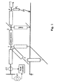
- Further problems with fault location in DN's, are that, in contrary to transmission lines, the distribution networks are usually nonhomogeneous, with branches and loads along the line which makes the fault location (FL) accuracy difficult. A general scheme of such a network is presented in Fig. 1. The fault-loop impedance estimated by FL at the substation and used as a direct measure of a distance to fault is corrupted by intermediate loads and branches that makes accurate fault location difficult. Three fundamental factors contribute to this:
- a fault-loop as seen from the substation may contain different cable sections with different equivalent parameters what can not be regarded as homogenous circuit, therefore no classical FL methods may be used;
- in the case of a DN line, there are often loads located between the fault point and the busbar; since the loads change and are unknown to the FL it is difficult to compensate for them;
- resistance at the fault point introduces equivalent fault impedance which value and character depends on the equivalent network parameters beyond the fault, this is also difficult to compensate for.
- By means of a method and a device according to the invention, determination of the distance to the fault on a faulty line of a Distribution Network (DN) may be performed, wherein the method takes into consideration the influences of non-homogenities, branches and loads of the DN. Further the method according to the invention is not dependent of where in the network measurements are being made, i e does not depend on if the currents and voltages of each line or branch are measured separately or if the voltage and sum current for all the lines are measured centrally.
- The principle of distance determination according to the invention is particularly useful for cable networks but may also advantageously be used for overhead line networks.
- The method proposed for this invention overcomes the difficulties discussed above by delivering a method for fault location in distribution networks characterised by the features of claim 1. First, the equivalent positive- ( Z f / 1k ) and zero-sequence ( Z f / 0k ) impedance of the network is computed in pre-fault steady-state for all M nodes of the network based on existing topology, loads and feeder parameters. Second, after the fault, the specific fault-loop parameters are calculated depending on the fault-loop type (phase-phase or phase-ground) and the place of measurements (at the supplying transformer or at the faulty feeder).
- The fault location is determined as a result of checking the following set of conditions:

- The final distance to fault will be chosen when the condition as in (A) is fulfilled. The method of calculation of the parameters ( Z 1 f , I p , I pN ) depends on the place of measurement (at the substation or the feeder).
- With the present invention it is possible to determine the distance to fault in a very accurate and reliable way. Especially in distribution networks including a plurality of different line or cable sections and with branches and loads along the lines, the present invention takes this into account by utilising fault loop approaches depending on the type of fault and going through the consecutive nodes of the network calculating the residual impedance in order to arrive at a distance value.
- These and other aspects of, and advantages with the present invention will become apparent from the detailed description and from the accompanying drawings.
- In the following detailed description of the invention, reference will be made to the accompanying drawings, of which
- Fig. 1 shows a basic arrangement of a fault locator for a distribution network,
- Fig. 2 shows a scheme of a network for a phase-to-phase fault at node k,
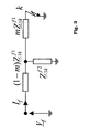
- Fig. 3 shows an equivalent scheme for feeder impedance calculation,
- Fig. 4 a shows an equivalent scheme for a phase-to-phase fault loop from the substation to the fault point,
- Fig. 4b the scheme according to Fig. 4a beyond the fault point,
- Fig. 5a shows an equivalent scheme for a phase-to-ground fault loop from the substation to the fault point,
- Fig. 5b the scheme according to Fig. 5a beyond the fault point, and
- Fig. 6 shows an embodiment of a device according to the invention for a fault location on one of the lines included in a network.
-
- The basic concept of the method of the present invention is to determine the fault location as a result of checking the following set of conditions:

- The fundamental assumptions considering the proposed fault locating algorithm for DN networks are summarized as follows:
- 1. The algorithm uses the substation voltages (three signals per substation, one signal per phase) and currents: taken from supplying transformer when centralized Fault Recorder (FR) is installed or from the faulty feeder when FRs are installed at each of the feeder. This is an advantage of the method, not a constraint. If there are FRs installed on some feeders, the data recorded by them is used for fault location (Fig. 1). If a feeder without a FR becomes faulty, the proposed method makes it possible to compute the fault impedance based only on the transformers current and busbar voltages. The adequate method for the last case is given in the Swedish Patent, No 9800741-2, "Fault Location in MV-distribution System".
- 2. The average values of loads along each feeder are known.
- 3. The electrical parameters of each section of the feeder are known.
- 4. At least one cycle of faulty signals is recorded.
-
- The data mentioned in points 2 and 3, the topology of the network, comprising electrical data such as the number of lines, branches, lengths of lines between branches and the respective line impedances and of actual loads on the lines and loads at the lines, are used for steady-state network impedance calculation, and according to the algorithm used in the present invention for distance to fault calculation, one should calculate impedance Z f / 1k and Z f / 0k for steady-state condition and parameters Z 1 f , k I, Z 1 N from measurements according to
- 1. calculate the network impedance for a given feeder for positive- and
zero-sequence schemes for steady-state condition. Full set of these
data includes of the following parameters:
- positive ( Z 1 L ) and zero-sequence ( Z 0 L ) series impedance of all line section;
- positive ( Z 1 k ) and zero-sequence ( Z 0 k ) equivalent shunt impedance for all network nodes;
- positive ( Z f / 1k ) and zero-sequence ( Z f / 0k ) impedance as seen from the substation to all k = 1..M network nodes (these impedances are calculated under assumption that a fault with no resistance takes place at the considered k node); the impedance Z f / 1k is then split into impedance Z f / 1 1k and Z f / 2 1k as in Fig. 3 with assumed coefficient 0 < m ≤ 1;
- positive ( Z u / 1k ) and zero-sequence ( Z u / 0k ) impedance as seen from the consecutive node k to the end of the network;
-
- All these parameters are calculated from the line parameters and values of loads with regard of the feeder configuration by use of a known method, e.g. nodal voltage equation. Reference is made to B.M. WEEDY, "Electric Power Systems". John Willey & Sons Ltd. 1990, Chapter 7. 'Fault Analysis', pp. 251-299, for details regarding nodal voltage equation. Results of the calculation form a data set in which the node k is described by the following impedance vector: [ Z 1 k Z 0 k Z f / 1 1k Z f / 2 1k Z u / 1k Z u / 0k ]. Moreover, each feeder section is described by two impedances: [ Z 1 L Z 0 L ]. The data from the calculations are conveniently stored in a database.
- The two parameters k I, Z 1 N depend on I p, I pN . Again, we will consider two cases depending on the fault-loop type and place of measurements.
- As a summary of the detailed description given in patent SE9800741-2, the currents Ip, IpN can be defined as follows:
I ph - when measurements are in the feeder,
I N = I A + I B + I C - when measurements are in the feeder, - C0k - zero-sequence capacitance of the faulty feeder,
- CC 0 - zero-sequence capacitance of the whole MV network,
- S lk and S Σ pre-fault loads of the faulty line and all the lines, respectively.
- Z pre = V pre / I pre - pre-fault positive-sequence impedance at the supplying transformer,
- index ph pointed to the faulty phase.
-
- Moreover, the positive sequence fault-loop impedance Z 1 f seen from the substation for phase-to-phase fault can be obtained from division of adequate voltage drop by difference of currents:
- The positive sequence loop for phase-to-ground fault is obtained as follows.
- For homogenous line the positive sequence fault-loop impedance seen from the substation is determined from the following relation
- Z ' / 0, Z ' / 1- zero and positive sequence impedance per length of the faulted feeder,
- I p , I pN - as in equations (4-5).
-
- For a feeder including sections with different types of cable coefficient k kN can not be calculated according to equation (8) because, in general, they have different per kilometer zero- and positive sequence parameters. In this case equation (8) may be rewritten in a form:
Substituting equation (9) into equation (7) one obtains the fault-loop impedance - Relation (11) is the basis for invented method according to equations (1-3) for phase-to-ground faults. The parameters k I and Z 1 N can be calculated from measurements whereas Z f / lk and Z f / 0k Z f 0 k are actual positive- and zero-sequence impedance of a fault-loop. The last can be obtained from off-line calculation based on network parameters.
- Left side of equation (11) - Z f / 1k - represents equivalent positive-sequence fault loop impedance seen from the substation. At the right side of equation (11) there is combination of the positive- and zero-sequence measurements available at the substation ( Z 1 N , k I ) and zero-sequence impedance of the network from the substation to the fault point Z f / 0k .
- Having the network impedance Z f / 1k and Z f / 0k for steady-state condition, and fault-loop parameters: Z 1 f , k I, Z 1 N given from measurements according to the equations (2) and (3) with respect to the above relations it is possible to utilise the criterion (1) for distance to fault calculation.
- The final distance to fault will be chosen when the condition as in (1) is fulfilled.
- Two different algorithms are used depending of the fault-loop type: phase-to-phase fault loop and phase-to-ground fault loop.
- Consider the phase-to-phase fault at node k of the network as in Fig. 2. It is assumed that the impedance Z f / 1k (positive-sequence network impedance as seen from the substation under assumption that the fault with no resistance occurs at the node k) is known from steady-state calculation and Z 1 f is obtained from measurement according to (6).
- For further analysis the fault loop seen from the substation is represented by an equivalent scheme as in Fig. 3. The following condition is fulfilled for this scheme:
- Representation of the impedance Z f / 1k in a form as in Fig. 3 provides a possibility to include the fault resistance in a fault-loop as shown in Fig. 4a. The residual impedance ΔZf represents the equivalent impedance involved in fault-loop due to the fault resistance Rf if the fault occurs at node k or behind them. The equivalent scheme for representation of the impedance ΔZf is presented in Fig. 4b. Here:
- Z 1 k - equivalent shunt impedance at node k,
- Z L - series impedance of the cable section between nodes k, k+1,
- Z u / 1
( k +1)- equivalent impedance of the network seen from the node k+1 to the end of the feeder.
The impedance Z u / 1 -
- The distance to fault df [m] is determined as a sum of distance d [m] from substation to node k (Fig. 4b) and distance xlk [m] inside a given section:
- The algorithm for distance x calculation is derived as follows:
- 1. The fault-loop impedance Z 1 f measured at the substation meets
the following relation (Fig.4a)

- 2. After rearranging of (15) the value of residual impedance can be
obtained

- 3. The impedance ΔZ f represents the scheme seen from the node k to
the fault place what can be determined as

- 4. Right sides of equations (16) and (17) should be equal, which leads
to determination of unknown fault resistance
where


- 5. Value of x can be obtained from (18) under condition that the fault
resistance takes real value

-
- After rearranging one obtainswhere


- First root of (20) takes imaginary value so, finally, distance to a fault is determined fromThe distance to fault is then calculated according to equation (14).

- Equivalent scheme of the fault-loop (Fig. 5) is similar as for phase-to-phase case. Instead of Z 1 f now the impedance form of equation (10) is used. Taking this into consideration, the algorithm for distance x [p.u.] to the fault at section k, k+1 is derived as follows:
- 1. The fault-loop impedance Z f / 1k Z 1 N - k IZ f / 0 k 0measured at the
substation meets the following relation (Fig. 5a)

- 2. After rearranging of (22) the value of residual impedance can be
obtained

- 3. The impedance Δ Z f represents the scheme seen from the node k to
the fault place what can be determined as (Fig. 5b)
where index e is related to the equivalent impedance in scheme on Fig. 5b.

The equivalent impedance is calculated from positive- and zero-sequence impedance of the particular element according to the following relations: - 4. Right sides of equations (23) and (24) should be equal which leads
to determination of unknown fault resistance
where


- 5. Value of x can be obtained from equation (26) under condition that
the fault resistance takes a real value

-
- Under the same conditions as for phase-to-phase fault one obtainswhere
 The distance to fault is then calculated according to equation (14).
- An example of a device according to the invention for fault location on one of the lines included in a distribution network is clear from Figure 6 and comprises:
- a fault locator 6,
- voltage and current measuring devices 4 and 5, with filters FI, 8 and Fv, 9 for continuously inputting to the fault locator measured values of current and voltage values, measured at an MV station, for all the lines included in the network,
- a unit MN, 10, for inputting MV network data to the fault locator, and
- a unit MF, 11, for inputting information about the type of fault and about which line has become faulty, after a fault has occurred.
- The fault locator 6 comprises:
- a memory, 6a, for storing consecutive sequences of measured input data which enable determination of measured values of voltage and current immediately prior to and after a fault has occurred, and a memory for storing input network data,
- a unit EF, 6b, for receiving information about the type of fault and about which line has become faulty,
- calculating methods, 6c, for calculating, on the basis of input data, the distance from the MV station to the site of the fault,
- a unit EA, 6d, for supplying a value of the calculated distance to fault.
- The network data which, via the unit MN, 10, are to be input into the fault locator comprise:
- information about the configuration and topology of the MV network, that is, how network, lines and branches are connected to the MV network,
- information about the length and impedance of the line sections,
- information about the load impedance in all the branches,
- information about the positive-sequence capacitance of all the lines to ground.
- The network data which, after a fault has occurred, are to be input into the fault locator via the unit MF, 11 comprise
- information about the type of fault, that is, if it is a phase-to-phase fault or if it is a phase-to-ground fault,
- information about which line has become faulty.
- The information about the type of fault and which line has become faulty is obtained from a superordinate protection and expert system.
- When a distance to fault from the MV station has been calculated, this is presented via the unit EA, 6d, for example on a visual display unit 12.
- A device according to the invention for fault location on one of the lines included in DN may be designed in a plurality of ways similar to that shown in Figure 6. Thus, for example, the filters 8 and 9 for filtering measured data for current and voltage and the input units 10 and 11 for network data and fault information may be more or less integrated into the fault locator 6. The device also comprises one or more micro computers. The micro processor (or processors) comprises a central processing unit CPU performing the steps of the method according to the invention. This is performed with the aid of a dedicated computer program, which is stored in the program memory. It is to be understood that the computer program may also be run on a general purpose industrial computer instead of a specially adapted computer.
- The software includes computer program code elements or software code portions that make the computer perform the method using equations, algorithms, data and calculations previously described. A part of the program may be stored in a processor as above, but also in a ROM, RAM, PROM or EPROM chip or similar. The program in part or in whole may also be stored on, or in, other suitable computer readable medium such as a magnetic disk, CD-ROM or DVD disk, hard disk, magneto-optical memory storage means, in volatile memory, in flash memory, as firmware, or stored on a data server.
- The method proposed in this invention realises the procedure for the fault location in distribution networks in the following steps:
- 1. For a given feeder calculate the network impedance for positive- and
zero-sequence schemes for steady-state condition and store them into
database. Full set of these data includes the following parameters:
- positive ( Z 1 L ) and zero-sequence ( Z 0 L ) series impedance of all line section;
- positive ( Z 1 k ) and zero-sequence ( Z 0 k ) equivalent shunt impedance for all network nodes;
- positive ( Z f / 1 k ) and zero-sequence ( Z f / 0 k ) impedance as seen from the substation to all k = 1..M network nodes (these impedance are calculated under assumption that a fault with no resistance take place at the considered k node); the impedance Z f / 1 k is then split into impedance Z f / 1 1 k and Z f / 2 1 k as in Fig. 3 with assumed coefficient 0<m≤1;
- positive ( Z f / 1 k ) and zero-sequence ( Z u / 0 k ) impedance as seen from the consecutive node k to the end of the network;
After the fault detection the procedure depends on the type of fault.
For phase-to-phase fault the following steps are realized: - 2. The impedance Z 1 f is calculated according to equation (6);
- 3. Going through the consecutive nodes the residual impedance Δ Z f is
calculated as in equation (16) and next the distance x according to
equation (21). This step is continued until x < 1 and then full
distance is determined according to equation (14).
For phase-to-ground fault the following steps are realized: - 4. The currents I p and I pN are calculated according to equations (4-5)
- depending on the place of measurement;
- 5. Parameters k I , Z 1 N and impedance Z 1 f are calculated as in equations (10-12);
- 6. Going through the consecutive nodes the residual impedance Δ Z f is calculated as in equation (24) and next the distance x according to equation (28). This step is continued until x < 1 and then full distance is determined according to equation (14).
-
- It is to be understood that the embodiments described above and shown on the drawings are to be regarded as non-limiting examples of the present invention and that it is defined by the appended patent claims.
Claims (17)
- Method for location of a fault which has occurred on one of a plurality of lines in a power distribution network where the location is performed with the aid of measured values of the common supply voltage of the said plurality of lines and the currents of the said plurality of lines after the occurrence of a fault; calculating the equivalent positive-sequence impedance Z f / 1 k and zero-sequence impedance Z f / 0 k of the network in a pre-fault steady state for all M nodes based on knowledge of the configuration and topology of the network, and obtaining, via a superordinate protection system, which of the said plurality type of lines has become faulty and which fault has occurred, characterised by
calculating the equivalent impedance Z ek using a fault loop calculation depending on the fault type aswhere
and checking if - Method according to claim 1, characterised in that I p, I pN are defined as
I ph - when measurements are in the feeder,C0k - zero-sequence capacitance of the faulty feeder,CC 0 - zero-sequence capacitance of the whole MV network,S lk and S Σ pre-fault loads of the faulty line and all the lines, respectively. - Method according to claim 2 for a phase-to-ground fault, characterised in calculating impedance Z 1 f according tocalculating distance x from node to fault as
 and continuing until x< 1.
- Method according to claim 2 for a phase-to-phase fault, characterised in calculating impedance Z 1 f according to
calculating the residual impedance going through consecutive nodes ascalculating distance x from node to fault as and continuing until x<1.
- Method according to claim 3 or 4, characterised in determining the distance to fault df as
- Device (6) for location of a fault which has occurred on one of a plurality of lines in a power distribution network comprising means for measuring values of the common supply voltage of the plurality of lines and the currents of the plurality lines before and after the occurrence of a fault; means (10) for calculating the equivalent positive-sequence impedance Z f / 1 k and zero-sequence impedance Z f / 0 k of the network in a pre-fault steady state for all M nodes; information storage means (10) containing information regarding the configuration and topology of the network; which device is connected to a superordinate protection system, for obtaining information regarding which of the said plurality of lines has become faulty and which type of fault has occurred, characterised in
means (6c) for calculating the equivalent impedance Z ek using fault loop calculation depending on the fault type aswhere
and checking if - Device according to claim 6, , characterised in means for defining I p , I pN as
I ph - when measurements are in the feeder,
I N = I A + I B + I C - when measurements are in the feeder,C0k - zero-sequence capacitance of the faulty feeder,CC0 - zero-sequence capacitance of the whole MV network,S lk and S Σ pre-fault loads of the faulty line and all the lines, respectively. - Device according to claim 7 for a phase-to-ground fault, characterised in means for calculating impedance Z 1 f according tomeans for calculating distance x from node to fault as
 and continuing until x<1.
- Device according to claim 7 for a phase-to-phase fault, characterised in means for calculating impedance Z 1 f according to
means for calculating the residual impedance going through consecutive nodes asmeans for calculating distance x from node to fault as and continuing until x< 1.
- Device according to claim 8 or 9, characterised in means for determining the distance to fault df as
- Use of a device according to any of claims 6 to 10 for determining the distance to a fault in a distribution network.
- Computer program product comprising computer code means and/or software code portions for making a computer perform a method based on; measuring values of the common supply voltage of a plurality of lines and the currents of the said plurality of lines after the occurrence of a fault in a distribution network; calculating the equivalent positive-sequence impedance Z f / 1 k and zero-sequence impedance Z f / 0 k of the network in a pre-fault steady state for all M nodes based on knowledge of the configuration and topology of the network and of electrical data such as the number of lines, branches, lengths of lines between branches and the respective line impedances and of actual loads on the lines and loads at the lines, and; obtaining via a superordinate protection system, which line has become faulty and which type of fault has occurred, and performing the further steps of:wherecalculating the equivalent impedance Z ek using fault loop calculation depending on the fault type as

and checking if - Computer program product according to claim 12, characterised in that it defines I p, I pN as
I ph - when measurements are in the feeder,
I N = I A + I B + I C - when measurements are in the feeder,C0k - zero-sequence capacitance of the faulty feeder,CC 0 - zero-sequence capacitance of the whole MV network,S lk and S Σ pre-fault loads of the faulty line and all the lines, respectively. - Computer program product according to claim 13 for a phase-to-ground fault, characterised by calculating impedance Z 1 f according tocalculating distance x from node to fault as
 and continuing until x<1.
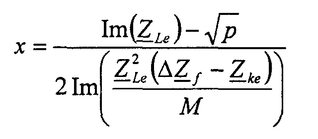
- Computer program product according to claim 13 for a phase-to-phase fault, characterised by calculating impedance Z 1 f according to
calculating the residual impedance going through consecutive nodes ascalculating distance x from node to fault as and continuing until x<1.
- Use of a computer program product according to any of claims 12-15 to determine a distance to a fault in a Medium Voltage power distribution network.
- A computer readable medium comprising computer code means according to any of claims 12-15.
Applications Claiming Priority (2)
| Application Number | Priority Date | Filing Date | Title |
|---|---|---|---|
| SE0002608 | 2000-07-11 | ||
| SE0002608A SE522376C2 (en) | 2000-07-11 | 2000-07-11 | Method and device for fault location for distribution networks |
Publications (4)
| Publication Number | Publication Date |
|---|---|
| EP1172660A2 true EP1172660A2 (en) | 2002-01-16 |
| EP1172660A3 EP1172660A3 (en) | 2005-12-21 |
| EP1172660B1 EP1172660B1 (en) | 2008-01-09 |
| EP1172660B9 EP1172660B9 (en) | 2008-06-18 |
Family
ID=20280445
Family Applications (1)
| Application Number | Title | Priority Date | Filing Date |
|---|---|---|---|
| EP01202430A Expired - Lifetime EP1172660B9 (en) | 2000-07-11 | 2001-06-25 | Method and device for fault location in distribution networks |
Country Status (7)
| Country | Link |
|---|---|
| US (1) | US6483435B2 (en) |
| EP (1) | EP1172660B9 (en) |
| AT (1) | ATE383584T1 (en) |
| CA (1) | CA2352700C (en) |
| DE (1) | DE60132276T2 (en) |
| ES (1) | ES2299465T3 (en) |
| SE (1) | SE522376C2 (en) |
Cited By (12)
| Publication number | Priority date | Publication date | Assignee | Title |
|---|---|---|---|---|
| WO2008131707A1 (en) * | 2007-04-26 | 2008-11-06 | Siemens Aktiengesellschaft | Method for determining a parameter set describing electric parameters of a route section of a magnetic suspension railway |
| EP2083278A1 (en) | 2008-01-25 | 2009-07-29 | ABB Technology AG | Method and apparatus for determining location of phase-to-phase fault |
| CN102411117A (en) * | 2011-08-09 | 2012-04-11 | 中国电力科学研究院 | Method for positioning short-circuit fault of distribution network based on distributed intelligent multi-calibration |
| CN103048587A (en) * | 2012-12-12 | 2013-04-17 | 深圳供电局有限公司 | Method, device and system for positioning faults of power distribution network with distributed power supply |
| CN103439629A (en) * | 2013-08-05 | 2013-12-11 | 国家电网公司 | Power distribution network fault diagnosis system based on data grid |
| CN103513157A (en) * | 2013-08-05 | 2014-01-15 | 国家电网公司 | Fault locating method of smart power distribution network in distribution line multi-power-supply-point environment |
| WO2015085286A1 (en) * | 2013-12-06 | 2015-06-11 | Abb Inc. | Systems and methods for identifying faulted segments in multiphase power networks |
| WO2016007217A1 (en) * | 2014-07-11 | 2016-01-14 | Abb Inc. | Decision support system for outage management and automated crew dispatch |
| CN105510771A (en) * | 2015-12-25 | 2016-04-20 | 北京四方继保自动化股份有限公司 | Hybrid-voltage common-tower four-loop two-phase-cross-three-phase cross voltage fault current calculation method |
| CN107064749A (en) * | 2017-06-20 | 2017-08-18 | 国网山东省电力公司莱芜供电公司 | A kind of Fault Locating Method of complicated distribution line |
| CN109470988A (en) * | 2018-10-10 | 2019-03-15 | 国网浙江省电力有限公司杭州供电公司 | A kind of fault localization system and method suitable for T-type transmission line of electricity |
| CN110488159A (en) * | 2019-09-19 | 2019-11-22 | 广东电网有限责任公司 | A kind of application method of distribution O&M monitoring device |
Families Citing this family (51)
| Publication number | Priority date | Publication date | Assignee | Title |
|---|---|---|---|---|
| US7248158B2 (en) * | 2000-04-14 | 2007-07-24 | Current Technologies, Llc | Automated meter reading power line communication system and method |
| US6651013B1 (en) * | 2000-11-16 | 2003-11-18 | International Business Machines Corporation | Method and apparatus for determining the location of a short in an electrical wire network |
| FI118491B (en) * | 2005-06-29 | 2007-11-30 | Abb Oy | Procedures and systems for locating earth faults |
| US8010811B2 (en) * | 2006-02-02 | 2011-08-30 | Watlow Electric Manufacturing Company | Power controller coupling assemblies and methods |
| US7461360B1 (en) * | 2006-04-11 | 2008-12-02 | William Wai Yan Ho | Validating very large network simulation results |
| US8077049B2 (en) | 2008-01-20 | 2011-12-13 | Current Technologies, Llc | Method and apparatus for communicating power distribution event and location |
| US8566046B2 (en) * | 2008-01-21 | 2013-10-22 | Current Technologies, Llc | System, device and method for determining power line equipment degradation |
| US20100007354A1 (en) * | 2008-07-08 | 2010-01-14 | Deaver Sr Brian J | System and Method for Predicting a Fault in a Power Line |
| US8797018B2 (en) * | 2010-01-22 | 2014-08-05 | Schweitzer Engineering Laboratories, Inc. | Apparatus and method for identifying the phase and terminal for power system devices |
| US8525522B2 (en) | 2010-04-21 | 2013-09-03 | Schweitzer Engineering Laboratories Inc | Fault location in electric power delivery systems |
| US8558551B2 (en) | 2010-04-21 | 2013-10-15 | Schweitzer Engineering Laboratories Inc | Fault location in electric power delivery systems |
| US8942954B2 (en) | 2010-09-16 | 2015-01-27 | Schweitzer Engineering Laboratories, Inc. | Fault location in a non-homogeneous electric power line |
| US8941387B2 (en) * | 2010-10-12 | 2015-01-27 | Howard University | Apparatus and method for fault detection and location determination |
| US8810251B2 (en) | 2011-08-31 | 2014-08-19 | General Electric Company | Systems, methods, and apparatus for locating faults on an electrical distribution network |
| US9229036B2 (en) | 2012-01-03 | 2016-01-05 | Sentient Energy, Inc. | Energy harvest split core design elements for ease of installation, high performance, and long term reliability |
| CN102520318B (en) * | 2012-01-04 | 2014-02-05 | 国家电网公司 | Fault recognition method for electric transmission line |
| US9182429B2 (en) | 2012-01-04 | 2015-11-10 | Sentient Energy, Inc. | Distribution line clamp force using DC bias on coil |
| RU2516371C1 (en) * | 2013-02-05 | 2014-05-20 | Общество с ограниченной ответственностью "Исследовательский центр "Бреслер" | Method for determination of damaged feeder at earth fault in distributing mains |
| US9835673B2 (en) * | 2013-04-12 | 2017-12-05 | Mitsubishi Electric Research Laboratories, Inc. | Method for analyzing faults in ungrounded power distribution systems |
| US9476931B2 (en) | 2014-02-07 | 2016-10-25 | Mitsubishi Electric Research Laboratories, Inc. | Method for fault location analysis of ungrounded distribution systems |
| US9476930B2 (en) | 2014-02-07 | 2016-10-25 | Mitsubishi Electric Research Laboratories, Inc. | Locating multi-phase faults in ungrounded power distribution systems |
| RU2572364C1 (en) * | 2014-10-09 | 2016-01-10 | Общество с ограниченной ответственностью "Исследовательский центр "Бреслер" | Method for determination of damaged section in branched distributing network |
| CN104330709B (en) * | 2014-11-28 | 2017-03-01 | 国家电网公司 | A kind of isolated neutral system singlephase earth fault Section Location |
| US9954354B2 (en) | 2015-01-06 | 2018-04-24 | Sentient Energy, Inc. | Methods and apparatus for mitigation of damage of power line assets from traveling electrical arcs |
| US9581649B2 (en) * | 2015-02-16 | 2017-02-28 | Texas Instruments Incorporated | Method and apparatus for load fault detection |
| US9984818B2 (en) | 2015-12-04 | 2018-05-29 | Sentient Energy, Inc. | Current harvesting transformer with protection from high currents |
| CN105550790B (en) * | 2016-03-08 | 2019-08-06 | 重庆大学 | Interconnected network idle work optimization calculation method based on non-topological approach equivalence |
| CN105787672B (en) * | 2016-03-22 | 2019-12-03 | 国网上海市电力公司 | A kind of building electrical energy saving method for early warning |
| WO2017218558A1 (en) * | 2016-06-14 | 2017-12-21 | Schweitzer Engineering Laboratories, Inc. | Phase selection for traveling wave fault detection systems |
| CN106383296B (en) * | 2016-11-02 | 2019-03-08 | 华北电力大学(保定) | A kind of improvement impedance type active power distribution network Fault Location Algorithm based on phasor analysis |
| CN106600452B (en) * | 2016-11-11 | 2020-07-07 | 国网新疆电力公司巴州供电公司 | Power distribution network traveling wave fault positioning method based on time analysis matrix and cluster analysis |
| US10634733B2 (en) | 2016-11-18 | 2020-04-28 | Sentient Energy, Inc. | Overhead power line sensor |
| US10094878B1 (en) | 2017-06-23 | 2018-10-09 | Texas Instruments Incorporated | Winding fault detection using inverter harmonics |
| CN108108584B (en) * | 2017-11-14 | 2022-05-03 | 广东电网有限责任公司电力调度控制中心 | Short-circuit parameter acquisition method and system for three-phase asymmetric equipment of power system |
| US10775448B2 (en) | 2018-06-18 | 2020-09-15 | Schweitzer Engineering Laboratories, Inc. | Automatic phase identification for electric power delivery lines |
| US11041915B2 (en) | 2018-09-18 | 2021-06-22 | Sentient Technology Holdings, LLC | Disturbance detecting current sensor |
| US11476674B2 (en) | 2018-09-18 | 2022-10-18 | Sentient Technology Holdings, LLC | Systems and methods to maximize power from multiple power line energy harvesting devices |
| US11125832B2 (en) | 2018-12-13 | 2021-09-21 | Sentient Technology Holdings, LLC | Multi-phase simulation environment |
| US11609590B2 (en) | 2019-02-04 | 2023-03-21 | Sentient Technology Holdings, LLC | Power supply for electric utility underground equipment |
| CN110350510B (en) * | 2019-05-23 | 2023-04-28 | 国网河南省电力公司郑州供电公司 | Power distribution network power supply recovery method considering fault influence degree |
| CN112034305A (en) * | 2020-08-31 | 2020-12-04 | 国网福建省电力有限公司检修分公司 | Single-phase grounding voltage current phase comparison fault location method for ultra-high voltage alternating current transmission line |
| CN112305456A (en) * | 2020-10-26 | 2021-02-02 | 国网四川省电力公司电力科学研究院 | Method and device for obtaining equivalent impedance under fault of broken line of grounding electrode circuit |
| CN112630587A (en) * | 2020-11-11 | 2021-04-09 | 大唐水电科学技术研究院有限公司 | Single-circuit three-phase disconnection fault analysis method for four-circuit line erected on same pole |
| RU2771222C1 (en) * | 2021-01-13 | 2022-04-28 | Акционерное общество "Сетевая компания" | Method for determining a damaged feeder in case of single phase to ground fault in a distribution electrical network |
| CN113589099B (en) * | 2021-07-13 | 2023-07-25 | 深圳供电局有限公司 | Method for realizing fault location in power distribution system with multi-branch transmission line |
| CN113406444B (en) * | 2021-08-03 | 2023-03-14 | 成都交大许继电气有限责任公司 | High-resistance fault identification method and system for traction network |
| CN113852053B (en) * | 2021-09-17 | 2023-11-14 | 国家电网有限公司 | Multi-source power distribution network protection method for power system |
| CN113835000B (en) * | 2021-09-23 | 2024-04-12 | 南方电网科学研究院有限责任公司 | Power distribution network fault positioning method, device, terminal and storage medium |
| TWI769962B (en) * | 2021-12-03 | 2022-07-01 | 新唐科技股份有限公司 | Driving apparatus and detection system for memory module failure detection, and memory device using the driving apparatus |
| CN116930685B (en) * | 2023-09-18 | 2023-12-05 | 青岛鼎信通讯科技有限公司 | Single-end ranging method suitable for single-phase earth fault of power distribution network |
| CN117192292B (en) * | 2023-11-07 | 2024-02-06 | 昆明理工大学 | Lightning grounding electrode line fault distance measurement method and system |
Citations (4)
| Publication number | Priority date | Publication date | Assignee | Title |
|---|---|---|---|---|
| US4107778A (en) * | 1976-02-18 | 1978-08-15 | Hitachi, Ltd. | Digital fault-location calculation system |
| WO1996032652A1 (en) * | 1995-04-13 | 1996-10-17 | Siemens Aktiengesellschaft | Distance measurement process |
| WO1999046609A1 (en) * | 1998-03-09 | 1999-09-16 | Abb Ab | Fault location in a medium-voltage network |
| EP1020729A2 (en) * | 1999-01-13 | 2000-07-19 | Alstom UK Limited | Fault detection for power lines |
Family Cites Families (7)
| Publication number | Priority date | Publication date | Assignee | Title |
|---|---|---|---|---|
| JPS5512817B1 (en) * | 1970-11-19 | 1980-04-04 | ||
| US4329727A (en) * | 1980-07-16 | 1982-05-11 | General Electric Company | Directional power distance relay |
| DE19545267C2 (en) | 1995-11-27 | 1999-04-08 | Siemens Ag | Method for obtaining faulty loops in signals characterizing a multi-phase electrical power supply network |
| US5839093A (en) * | 1996-12-31 | 1998-11-17 | Abb Transmit Oy | System for locating faults and estimating fault resistance in distribution networks with tapped loads |
| US5773980A (en) | 1997-01-30 | 1998-06-30 | Abb Power T&D Company, Inc. | One-terminal fault location system that corrects for fault resistance effects |
| US5796258A (en) * | 1997-01-30 | 1998-08-18 | Abb Power T&D Company, Inc. | Adaptive quadrilateral characteristic distance relay |
| JP2000214210A (en) * | 1999-01-20 | 2000-08-04 | Toshiba Corp | Accident point locater |
-
2000
- 2000-07-11 SE SE0002608A patent/SE522376C2/en not_active IP Right Cessation
-
2001
- 2001-06-25 EP EP01202430A patent/EP1172660B9/en not_active Expired - Lifetime
- 2001-06-25 ES ES01202430T patent/ES2299465T3/en not_active Expired - Lifetime
- 2001-06-25 DE DE60132276T patent/DE60132276T2/en not_active Expired - Lifetime
- 2001-06-25 AT AT01202430T patent/ATE383584T1/en not_active IP Right Cessation
- 2001-07-09 CA CA2352700A patent/CA2352700C/en not_active Expired - Fee Related
- 2001-07-11 US US09/901,638 patent/US6483435B2/en not_active Expired - Lifetime
Patent Citations (4)
| Publication number | Priority date | Publication date | Assignee | Title |
|---|---|---|---|---|
| US4107778A (en) * | 1976-02-18 | 1978-08-15 | Hitachi, Ltd. | Digital fault-location calculation system |
| WO1996032652A1 (en) * | 1995-04-13 | 1996-10-17 | Siemens Aktiengesellschaft | Distance measurement process |
| WO1999046609A1 (en) * | 1998-03-09 | 1999-09-16 | Abb Ab | Fault location in a medium-voltage network |
| EP1020729A2 (en) * | 1999-01-13 | 2000-07-19 | Alstom UK Limited | Fault detection for power lines |
Cited By (22)
| Publication number | Priority date | Publication date | Assignee | Title |
|---|---|---|---|---|
| US8198890B2 (en) | 2007-04-26 | 2012-06-12 | Siemens Aktiengesellschaft | Method for determination of a parameter set which describes electrical parameters of a track section of a magnetic levitation railroad |
| CN101652666B (en) * | 2007-04-26 | 2012-06-20 | 西门子公司 | Method for determining a parameter set describing electric parameters of a route section of a magnetic suspension railway |
| WO2008131707A1 (en) * | 2007-04-26 | 2008-11-06 | Siemens Aktiengesellschaft | Method for determining a parameter set describing electric parameters of a route section of a magnetic suspension railway |
| EP2083278A1 (en) | 2008-01-25 | 2009-07-29 | ABB Technology AG | Method and apparatus for determining location of phase-to-phase fault |
| CN102411117B (en) * | 2011-08-09 | 2014-07-02 | 中国电力科学研究院 | Method for positioning short-circuit fault of distribution network based on distributed intelligent multi-calibration |
| CN102411117A (en) * | 2011-08-09 | 2012-04-11 | 中国电力科学研究院 | Method for positioning short-circuit fault of distribution network based on distributed intelligent multi-calibration |
| CN103048587A (en) * | 2012-12-12 | 2013-04-17 | 深圳供电局有限公司 | Method, device and system for positioning faults of power distribution network with distributed power supply |
| CN103048587B (en) * | 2012-12-12 | 2016-01-20 | 深圳供电局有限公司 | There is the Fault Locating Method of the power distribution network of distributed power source, Apparatus and system |
| CN103439629A (en) * | 2013-08-05 | 2013-12-11 | 国家电网公司 | Power distribution network fault diagnosis system based on data grid |
| CN103513157A (en) * | 2013-08-05 | 2014-01-15 | 国家电网公司 | Fault locating method of smart power distribution network in distribution line multi-power-supply-point environment |
| CN103439629B (en) * | 2013-08-05 | 2016-11-02 | 国家电网公司 | Fault Diagnosis of Distribution Network systems based on data grids |
| WO2015085286A1 (en) * | 2013-12-06 | 2015-06-11 | Abb Inc. | Systems and methods for identifying faulted segments in multiphase power networks |
| CN106463945B (en) * | 2013-12-06 | 2019-02-12 | Abb公司 | The system and method for fault section in polyphase electric power network for identification |
| US10514412B2 (en) | 2013-12-06 | 2019-12-24 | Abb Inc. | Systems and methods for identifying faulted segments in multiphase power networks |
| CN106463945A (en) * | 2013-12-06 | 2017-02-22 | Abb公司 | Systems and methods for identifying faulted segments in multiphase power networks |
| WO2016007217A1 (en) * | 2014-07-11 | 2016-01-14 | Abb Inc. | Decision support system for outage management and automated crew dispatch |
| US9874593B2 (en) | 2014-07-11 | 2018-01-23 | Abb Inc. | Decision support system for outage management and automated crew dispatch |
| CN105510771A (en) * | 2015-12-25 | 2016-04-20 | 北京四方继保自动化股份有限公司 | Hybrid-voltage common-tower four-loop two-phase-cross-three-phase cross voltage fault current calculation method |
| CN107064749A (en) * | 2017-06-20 | 2017-08-18 | 国网山东省电力公司莱芜供电公司 | A kind of Fault Locating Method of complicated distribution line |
| CN109470988A (en) * | 2018-10-10 | 2019-03-15 | 国网浙江省电力有限公司杭州供电公司 | A kind of fault localization system and method suitable for T-type transmission line of electricity |
| CN110488159A (en) * | 2019-09-19 | 2019-11-22 | 广东电网有限责任公司 | A kind of application method of distribution O&M monitoring device |
| CN110488159B (en) * | 2019-09-19 | 2024-03-22 | 广东电网有限责任公司 | Application method of distribution network operation and maintenance monitoring equipment |
Also Published As
| Publication number | Publication date |
|---|---|
| US6483435B2 (en) | 2002-11-19 |
| CA2352700C (en) | 2010-05-25 |
| SE522376C2 (en) | 2004-02-03 |
| SE0002608D0 (en) | 2000-07-11 |
| EP1172660A3 (en) | 2005-12-21 |
| DE60132276D1 (en) | 2008-02-21 |
| DE60132276T2 (en) | 2009-01-15 |
| EP1172660B9 (en) | 2008-06-18 |
| US20020053912A1 (en) | 2002-05-09 |
| CA2352700A1 (en) | 2002-01-11 |
| ES2299465T3 (en) | 2008-06-01 |
| SE0002608L (en) | 2002-01-12 |
| ATE383584T1 (en) | 2008-01-15 |
| EP1172660B1 (en) | 2008-01-09 |
Similar Documents
| Publication | Publication Date | Title |
|---|---|---|
| US6483435B2 (en) | Method and device of fault location for distribution networks | |
| US9476931B2 (en) | Method for fault location analysis of ungrounded distribution systems | |
| EP1342096B1 (en) | Method and device for fault location | |
| EP2000811B1 (en) | Method for determining location of phase-to-earth fault | |
| EP1073911B1 (en) | Fault location in a medium-voltage network | |
| EP3179592B1 (en) | Distribution system analysis using meter data | |
| US20060291113A1 (en) | System and method for determining location of phase-to-earth fault | |
| EP1992954A1 (en) | Method for determining location of phase-to-earth fault | |
| WO1995024014A2 (en) | One-terminal data fault location system | |
| EP3482472B1 (en) | A method and system for locating a fault in a mixed power transmission line | |
| WO1998029752A1 (en) | System for locating faults and estimating fault resistance in distribution networks with tapped loads | |
| JP2006505768A (en) | Fault location using current and voltage measurements from one end of the track | |
| JP2015148610A (en) | Method and system for determining location of fault in ungrounded power distribution system | |
| Xiu et al. | Novel fault location methods for ungrounded radial distribution systems using measurements at substation | |
| WO2019166903A1 (en) | Method and device for fault location in a two-terminal transmission system | |
| WO2012000745A1 (en) | Method and apparatus for determining distance to phase-to-earth fault | |
| EP0464662B1 (en) | Method and means for fault location in a multi-terminal network | |
| Orozco-Álvarez et al. | Communication-less adaptive directional overcurrent protection strategy considering islanded mode detection in active distribution networks | |
| Sachdev et al. | Determining locations of faults in distribution systems | |
| EP3732759A1 (en) | Fault location in multi-terminal tapped lines | |
| Chen et al. | Fast and accurate fault detection/location algorithms for double‐circuit/three‐terminal lines using phasor measurement units | |
| Idris et al. | Two-terminal fault detection and location for hybrid transmission circuit | |
| Dzienis et al. | Accurate impedance based fault location algorithm using communication between protective relays | |
| JP7437583B2 (en) | Apparatus, system, and method for dual circuit transmission system | |
| CN114252726B (en) | Positioning method, medium and system for voltage sag source of power distribution system |
Legal Events
| Date | Code | Title | Description |
|---|---|---|---|
| PUAI | Public reference made under article 153(3) epc to a published international application that has entered the european phase |
Free format text: ORIGINAL CODE: 0009012 |
|
| AK | Designated contracting states |
Kind code of ref document: A2 Designated state(s): AT BE CH CY DE DK ES FI FR GB GR IE IT LI LU MC NL PT SE TR |
|
| AX | Request for extension of the european patent |
Free format text: AL;LT;LV;MK;RO;SI |
|
| PUAL | Search report despatched |
Free format text: ORIGINAL CODE: 0009013 |
|
| AK | Designated contracting states |
Kind code of ref document: A3 Designated state(s): AT BE CH CY DE DK ES FI FR GB GR IE IT LI LU MC NL PT SE TR |
|
| AX | Request for extension of the european patent |
Extension state: AL LT LV MK RO SI |
|
| 17P | Request for examination filed |
Effective date: 20060619 |
|
| 17Q | First examination report despatched |
Effective date: 20060721 |
|
| AKX | Designation fees paid |
Designated state(s): AT BE CH CY DE DK ES FI FR GB GR IE IT LI LU MC NL PT SE TR |
|
| 17Q | First examination report despatched |
Effective date: 20060721 |
|
| GRAP | Despatch of communication of intention to grant a patent |
Free format text: ORIGINAL CODE: EPIDOSNIGR1 |
|
| RIN1 | Information on inventor provided before grant (corrected) |
Inventor name: SAHA, MURARI Inventor name: ROSOLOWSKI, EUGENIUSZ |
|
| GRAS | Grant fee paid |
Free format text: ORIGINAL CODE: EPIDOSNIGR3 |
|
| GRAA | (expected) grant |
Free format text: ORIGINAL CODE: 0009210 |
|
| AK | Designated contracting states |
Kind code of ref document: B1 Designated state(s): AT BE CH CY DE DK ES FI FR GB GR IE IT LI LU MC NL PT SE TR |
|
| REG | Reference to a national code |
Ref country code: GB Ref legal event code: FG4D |
|
| REG | Reference to a national code |
Ref country code: CH Ref legal event code: EP |
|
| REG | Reference to a national code |
Ref country code: IE Ref legal event code: FG4D |
|
| REF | Corresponds to: |
Ref document number: 60132276 Country of ref document: DE Date of ref document: 20080221 Kind code of ref document: P |
|
| PG25 | Lapsed in a contracting state [announced via postgrant information from national office to epo] |
Ref country code: NL Free format text: LAPSE BECAUSE OF FAILURE TO SUBMIT A TRANSLATION OF THE DESCRIPTION OR TO PAY THE FEE WITHIN THE PRESCRIBED TIME-LIMIT Effective date: 20080109 |
|
| REG | Reference to a national code |
Ref country code: ES Ref legal event code: FG2A Ref document number: 2299465 Country of ref document: ES Kind code of ref document: T3 |
|
| NLV1 | Nl: lapsed or annulled due to failure to fulfill the requirements of art. 29p and 29m of the patents act | ||
| PG25 | Lapsed in a contracting state [announced via postgrant information from national office to epo] |
Ref country code: LI Free format text: LAPSE BECAUSE OF FAILURE TO SUBMIT A TRANSLATION OF THE DESCRIPTION OR TO PAY THE FEE WITHIN THE PRESCRIBED TIME-LIMIT Effective date: 20080109 Ref country code: FI Free format text: LAPSE BECAUSE OF FAILURE TO SUBMIT A TRANSLATION OF THE DESCRIPTION OR TO PAY THE FEE WITHIN THE PRESCRIBED TIME-LIMIT Effective date: 20080109 Ref country code: CH Free format text: LAPSE BECAUSE OF FAILURE TO SUBMIT A TRANSLATION OF THE DESCRIPTION OR TO PAY THE FEE WITHIN THE PRESCRIBED TIME-LIMIT Effective date: 20080109 |
|
| REG | Reference to a national code |
Ref country code: CH Ref legal event code: PL |
|
| PG25 | Lapsed in a contracting state [announced via postgrant information from national office to epo] |
Ref country code: AT Free format text: LAPSE BECAUSE OF FAILURE TO SUBMIT A TRANSLATION OF THE DESCRIPTION OR TO PAY THE FEE WITHIN THE PRESCRIBED TIME-LIMIT Effective date: 20080109 |
|
| ET | Fr: translation filed | ||
| PG25 | Lapsed in a contracting state [announced via postgrant information from national office to epo] |
Ref country code: PT Free format text: LAPSE BECAUSE OF FAILURE TO SUBMIT A TRANSLATION OF THE DESCRIPTION OR TO PAY THE FEE WITHIN THE PRESCRIBED TIME-LIMIT Effective date: 20080609 Ref country code: BE Free format text: LAPSE BECAUSE OF FAILURE TO SUBMIT A TRANSLATION OF THE DESCRIPTION OR TO PAY THE FEE WITHIN THE PRESCRIBED TIME-LIMIT Effective date: 20080109 |
|
| PG25 | Lapsed in a contracting state [announced via postgrant information from national office to epo] |
Ref country code: DK Free format text: LAPSE BECAUSE OF FAILURE TO SUBMIT A TRANSLATION OF THE DESCRIPTION OR TO PAY THE FEE WITHIN THE PRESCRIBED TIME-LIMIT Effective date: 20080109 Ref country code: SE Free format text: LAPSE BECAUSE OF FAILURE TO SUBMIT A TRANSLATION OF THE DESCRIPTION OR TO PAY THE FEE WITHIN THE PRESCRIBED TIME-LIMIT Effective date: 20080409 |
|
| PLBE | No opposition filed within time limit |
Free format text: ORIGINAL CODE: 0009261 |
|
| STAA | Information on the status of an ep patent application or granted ep patent |
Free format text: STATUS: NO OPPOSITION FILED WITHIN TIME LIMIT |
|
| 26N | No opposition filed |
Effective date: 20081010 |
|
| PG25 | Lapsed in a contracting state [announced via postgrant information from national office to epo] |
Ref country code: MC Free format text: LAPSE BECAUSE OF NON-PAYMENT OF DUE FEES Effective date: 20080630 |
|
| PG25 | Lapsed in a contracting state [announced via postgrant information from national office to epo] |
Ref country code: IE Free format text: LAPSE BECAUSE OF NON-PAYMENT OF DUE FEES Effective date: 20080625 |
|
| PG25 | Lapsed in a contracting state [announced via postgrant information from national office to epo] |
Ref country code: CY Free format text: LAPSE BECAUSE OF FAILURE TO SUBMIT A TRANSLATION OF THE DESCRIPTION OR TO PAY THE FEE WITHIN THE PRESCRIBED TIME-LIMIT Effective date: 20080109 |
|
| PG25 | Lapsed in a contracting state [announced via postgrant information from national office to epo] |
Ref country code: LU Free format text: LAPSE BECAUSE OF NON-PAYMENT OF DUE FEES Effective date: 20080625 |
|
| PG25 | Lapsed in a contracting state [announced via postgrant information from national office to epo] |
Ref country code: TR Free format text: LAPSE BECAUSE OF FAILURE TO SUBMIT A TRANSLATION OF THE DESCRIPTION OR TO PAY THE FEE WITHIN THE PRESCRIBED TIME-LIMIT Effective date: 20080109 |
|
| PG25 | Lapsed in a contracting state [announced via postgrant information from national office to epo] |
Ref country code: GR Free format text: LAPSE BECAUSE OF FAILURE TO SUBMIT A TRANSLATION OF THE DESCRIPTION OR TO PAY THE FEE WITHIN THE PRESCRIBED TIME-LIMIT Effective date: 20080410 |
|
| PGFP | Annual fee paid to national office [announced via postgrant information from national office to epo] |
Ref country code: ES Payment date: 20150626 Year of fee payment: 15 Ref country code: GB Payment date: 20150618 Year of fee payment: 15 |
|
| PGFP | Annual fee paid to national office [announced via postgrant information from national office to epo] |
Ref country code: IT Payment date: 20150622 Year of fee payment: 15 |
|
| REG | Reference to a national code |
Ref country code: FR Ref legal event code: PLFP Year of fee payment: 16 |
|
| GBPC | Gb: european patent ceased through non-payment of renewal fee |
Effective date: 20160625 |
|
| PG25 | Lapsed in a contracting state [announced via postgrant information from national office to epo] |
Ref country code: GB Free format text: LAPSE BECAUSE OF NON-PAYMENT OF DUE FEES Effective date: 20160625 |
|
| REG | Reference to a national code |
Ref country code: FR Ref legal event code: PLFP Year of fee payment: 17 |
|
| PG25 | Lapsed in a contracting state [announced via postgrant information from national office to epo] |
Ref country code: IT Free format text: LAPSE BECAUSE OF NON-PAYMENT OF DUE FEES Effective date: 20160625 |
|
| PGFP | Annual fee paid to national office [announced via postgrant information from national office to epo] |
Ref country code: DE Payment date: 20170621 Year of fee payment: 17 Ref country code: FR Payment date: 20170621 Year of fee payment: 17 |
|
| REG | Reference to a national code |
Ref country code: DE Ref legal event code: R082 Ref document number: 60132276 Country of ref document: DE Representative=s name: BECKER, KURIG, STRAUS, DE Ref country code: DE Ref legal event code: R081 Ref document number: 60132276 Country of ref document: DE Owner name: ABB SCHWEIZ AG, CH Free format text: FORMER OWNER: ABB AB, VAESTERAS, SE |
|
| PG25 | Lapsed in a contracting state [announced via postgrant information from national office to epo] |
Ref country code: ES Free format text: LAPSE BECAUSE OF NON-PAYMENT OF DUE FEES Effective date: 20160626 |
|
| REG | Reference to a national code |
Ref country code: ES Ref legal event code: FD2A Effective date: 20181129 |
|
| REG | Reference to a national code |
Ref country code: FR Ref legal event code: TP Owner name: ABB SCHWEIZ AG, CH Effective date: 20181106 |
|
| REG | Reference to a national code |
Ref country code: DE Ref legal event code: R119 Ref document number: 60132276 Country of ref document: DE |
|
| PG25 | Lapsed in a contracting state [announced via postgrant information from national office to epo] |
Ref country code: DE Free format text: LAPSE BECAUSE OF NON-PAYMENT OF DUE FEES Effective date: 20190101 Ref country code: FR Free format text: LAPSE BECAUSE OF NON-PAYMENT OF DUE FEES Effective date: 20180630 |