EP1168973B1 - An apparatus for tissue treatment - Google Patents
An apparatus for tissue treatment Download PDFInfo
- Publication number
- EP1168973B1 EP1168973B1 EP00910587A EP00910587A EP1168973B1 EP 1168973 B1 EP1168973 B1 EP 1168973B1 EP 00910587 A EP00910587 A EP 00910587A EP 00910587 A EP00910587 A EP 00910587A EP 1168973 B1 EP1168973 B1 EP 1168973B1
- Authority
- EP
- European Patent Office
- Prior art keywords
- light beam
- handpiece
- spot
- deflecting
- treating
- Prior art date
- Legal status (The legal status is an assumption and is not a legal conclusion. Google has not performed a legal analysis and makes no representation as to the accuracy of the status listed.)
- Expired - Lifetime
Links
- 238000011282 treatment Methods 0.000 title claims abstract description 82
- 239000013307 optical fiber Substances 0.000 claims description 17
- 230000005540 biological transmission Effects 0.000 claims description 3
- 210000004209 hair Anatomy 0.000 abstract description 24
- 210000003462 vein Anatomy 0.000 abstract description 11
- 230000000649 photocoagulation Effects 0.000 abstract description 5
- 210000001519 tissue Anatomy 0.000 description 60
- 210000003780 hair follicle Anatomy 0.000 description 18
- 238000001816 cooling Methods 0.000 description 14
- 239000000835 fiber Substances 0.000 description 10
- 230000001276 controlling effect Effects 0.000 description 9
- 238000006073 displacement reaction Methods 0.000 description 7
- 230000006870 function Effects 0.000 description 7
- 239000000126 substance Substances 0.000 description 6
- 238000010521 absorption reaction Methods 0.000 description 5
- 210000004204 blood vessel Anatomy 0.000 description 5
- 238000010438 heat treatment Methods 0.000 description 5
- 230000000881 depressing effect Effects 0.000 description 4
- 210000004369 blood Anatomy 0.000 description 3
- 239000008280 blood Substances 0.000 description 3
- 239000000110 cooling liquid Substances 0.000 description 3
- 238000010586 diagram Methods 0.000 description 3
- 239000012530 fluid Substances 0.000 description 3
- 239000002245 particle Substances 0.000 description 3
- 229910000980 Aluminium gallium arsenide Inorganic materials 0.000 description 2
- OKTJSMMVPCPJKN-UHFFFAOYSA-N Carbon Chemical compound [C] OKTJSMMVPCPJKN-UHFFFAOYSA-N 0.000 description 2
- 229910052799 carbon Inorganic materials 0.000 description 2
- 239000002537 cosmetic Substances 0.000 description 2
- 230000002500 effect on skin Effects 0.000 description 2
- 239000000463 material Substances 0.000 description 2
- 239000012528 membrane Substances 0.000 description 2
- 238000000034 method Methods 0.000 description 2
- 230000003287 optical effect Effects 0.000 description 2
- 238000009827 uniform distribution Methods 0.000 description 2
- 208000032544 Cicatrix Diseases 0.000 description 1
- 208000012661 Dyskinesia Diseases 0.000 description 1
- 208000015592 Involuntary movements Diseases 0.000 description 1
- 238000002679 ablation Methods 0.000 description 1
- 230000004913 activation Effects 0.000 description 1
- 230000015271 coagulation Effects 0.000 description 1
- 238000005345 coagulation Methods 0.000 description 1
- 239000012809 cooling fluid Substances 0.000 description 1
- 239000013078 crystal Substances 0.000 description 1
- 230000001934 delay Effects 0.000 description 1
- 230000000994 depressogenic effect Effects 0.000 description 1
- 230000000694 effects Effects 0.000 description 1
- 238000005516 engineering process Methods 0.000 description 1
- 210000002615 epidermis Anatomy 0.000 description 1
- 230000001815 facial effect Effects 0.000 description 1
- 238000005562 fading Methods 0.000 description 1
- 238000005286 illumination Methods 0.000 description 1
- 238000011835 investigation Methods 0.000 description 1
- 239000000203 mixture Substances 0.000 description 1
- 230000017311 musculoskeletal movement, spinal reflex action Effects 0.000 description 1
- 230000001338 necrotic effect Effects 0.000 description 1
- 238000001208 nuclear magnetic resonance pulse sequence Methods 0.000 description 1
- 230000001902 propagating effect Effects 0.000 description 1
- 230000001105 regulatory effect Effects 0.000 description 1
- 230000008672 reprogramming Effects 0.000 description 1
- 231100000241 scar Toxicity 0.000 description 1
- 230000037387 scars Effects 0.000 description 1
- 238000011269 treatment regimen Methods 0.000 description 1
- XLYOFNOQVPJJNP-UHFFFAOYSA-N water Substances O XLYOFNOQVPJJNP-UHFFFAOYSA-N 0.000 description 1
- 210000000707 wrist Anatomy 0.000 description 1
Images


Classifications
-
- A—HUMAN NECESSITIES
- A61—MEDICAL OR VETERINARY SCIENCE; HYGIENE
- A61B—DIAGNOSIS; SURGERY; IDENTIFICATION
- A61B18/00—Surgical instruments, devices or methods for transferring non-mechanical forms of energy to or from the body
- A61B18/18—Surgical instruments, devices or methods for transferring non-mechanical forms of energy to or from the body by applying electromagnetic radiation, e.g. microwaves
- A61B18/20—Surgical instruments, devices or methods for transferring non-mechanical forms of energy to or from the body by applying electromagnetic radiation, e.g. microwaves using laser
- A61B18/203—Surgical instruments, devices or methods for transferring non-mechanical forms of energy to or from the body by applying electromagnetic radiation, e.g. microwaves using laser applying laser energy to the outside of the body
-
- A—HUMAN NECESSITIES
- A61—MEDICAL OR VETERINARY SCIENCE; HYGIENE
- A61B—DIAGNOSIS; SURGERY; IDENTIFICATION
- A61B18/00—Surgical instruments, devices or methods for transferring non-mechanical forms of energy to or from the body
- A61B2018/00005—Cooling or heating of the probe or tissue immediately surrounding the probe
-
- A—HUMAN NECESSITIES
- A61—MEDICAL OR VETERINARY SCIENCE; HYGIENE
- A61B—DIAGNOSIS; SURGERY; IDENTIFICATION
- A61B18/00—Surgical instruments, devices or methods for transferring non-mechanical forms of energy to or from the body
- A61B2018/00315—Surgical instruments, devices or methods for transferring non-mechanical forms of energy to or from the body for treatment of particular body parts
- A61B2018/00452—Skin
- A61B2018/00476—Hair follicles
-
- A—HUMAN NECESSITIES
- A61—MEDICAL OR VETERINARY SCIENCE; HYGIENE
- A61B—DIAGNOSIS; SURGERY; IDENTIFICATION
- A61B18/00—Surgical instruments, devices or methods for transferring non-mechanical forms of energy to or from the body
- A61B18/18—Surgical instruments, devices or methods for transferring non-mechanical forms of energy to or from the body by applying electromagnetic radiation, e.g. microwaves
- A61B18/20—Surgical instruments, devices or methods for transferring non-mechanical forms of energy to or from the body by applying electromagnetic radiation, e.g. microwaves using laser
- A61B2018/2015—Miscellaneous features
- A61B2018/2025—Miscellaneous features with a pilot laser
-
- A—HUMAN NECESSITIES
- A61—MEDICAL OR VETERINARY SCIENCE; HYGIENE
- A61B—DIAGNOSIS; SURGERY; IDENTIFICATION
- A61B18/00—Surgical instruments, devices or methods for transferring non-mechanical forms of energy to or from the body
- A61B18/18—Surgical instruments, devices or methods for transferring non-mechanical forms of energy to or from the body by applying electromagnetic radiation, e.g. microwaves
- A61B18/20—Surgical instruments, devices or methods for transferring non-mechanical forms of energy to or from the body by applying electromagnetic radiation, e.g. microwaves using laser
- A61B2018/2035—Beam shaping or redirecting; Optical components therefor
- A61B2018/20351—Scanning mechanisms
- A61B2018/20359—Scanning mechanisms by movable mirrors, e.g. galvanometric
Definitions
- the present invention relates to an apparatus for tissue treatment, such as for hair removal and for photocoagulation of veins.
- tissue treatment such as cosmetic tissue treatment, such as dermal ablation, removal of hair, photocoagulation of veins, etc.
- cosmetic tissue treatment such as dermal ablation, removal of hair, photocoagulation of veins, etc.
- Hair removal may be effected by directing a laser beam at a hair follicle to destroy the hair follicle and its adjacent blood vessels by the heat produced by photothermolysis.
- coagulation of veins may be effected by directing a laser beam at the veins to coagulate the blood in the veins.
- tissue such as an epidermal layer, hair, veins, etc
- Residual heat may cause untreated cells to char and become necrotic, whereby scars may be formed.
- Light of a wavelength that is absorbed in a hair follicle and its adjacent blood vessels will be scattered in all directions when propagating from a tissue surface down to the hair follicle to be destroyed by the heat produced by photothermolysis. Therefore, it is required to illuminate a rather large spot on the tissue surface above the hair follicle(s) to be destroyed in order to increase the probability of photons being scattered in direction of the hair follicle(s). Simultaneously, the power of the illuminating light beam must be sufficient for enough heat to be generated to destroy the hair follicle and its adjacent blood vessels.
- spot size means the diameter of the spot in question.
- a handpiece according to claim 17 is also provided.
- the handpiece When the handpiece is kept in a fixed position in relation to a target surface that is illuminated by the treating light beam changing of the position of the deflecting means causes the treating light beam to traverse or scan the target surface along a curve.
- An area may be traversed or scanned by the treating light beam, e.g. by letting the treating light beam traverse or scan a meander like curve substantially covering the area or, by traversing or scanning the area line by line.
- the type, number and shape of curves traversed by the treating light beam in order to traverse a specific area is denoted the traversing pattern or the scan pattern.
- the area that is scanned or traversed by the treating light beam is denoted the scan area, the treatment area or the traversed area.
- the scanning may be performed stepwise as further explained below.
- the output power of the diode laser is less than 250 W, preferably less than 175 W, more preferably less than 125 W, most preferred approximately 80 W.
- the centre to centre distance between two succeeding spot positions is less than a spot diameter, such as between half a spot diameter and a diameter of the spot, preferably such as approximately half a spot diameter, most preferred such as two thirds a spot diameter, so as to provide for a controlled overlap of the spots resulting in an effective hair removal.
- a spot diameter such as between half a spot diameter and a diameter of the spot, preferably such as approximately half a spot diameter, most preferred such as two thirds a spot diameter, so as to provide for a controlled overlap of the spots resulting in an effective hair removal.
- the thus implied overlap ensures a uniform distribution of energy across the traversed tissue area, and thus a uniform removal of hairs.
- scan the tissue area line by line scanned successively in the same directions having a spot overlap such as mentioned above.
- the treating light beam traverses a line to be treated a first time and a second time stepwise with a step size being substantially greater than the diameter of the spot.
- the centre to centre distance between two succeeding treating spot positions may be thus be larger than a spot diameter, such as 1.5 times a spot diameter, preferably such as approx. four thirds a spot diameter, and still provide effective hair removal.
- the scanning may be performed so that the first traversing of the treating light beam illuminates a first sequence of spots and the second traversing of the treating light beam illuminates a second sequence of spots in the same line, the distance between the first illuminated spot in the first sequence and the first illuminated spot in the second sequence being substantially equal to half the size of the steps between succeeding illuminated spots in the first sequence.
- the scanning may thus be performed so that after treatment of succeeding treating spots in a scan line, the line is scanned again so that the areas, the intermediate spots, not having received treatment in the first scan due to the large distance between two succeeding spots are now treated so as to obtain an overlap as mentioned above. It may then be preferred to scan the tissue area along a curve constituted by lines scanned successively in the same direction having a spot overlap such as mentioned above.
- treating spots on adjacent lines are positioned so that spot centres on one line are positioned in between spot centres on an adjacent line, whereby spot overlap as mentioned above is also obtained from one line to adjacent lines.
- the centre to centre the distance between two succeeding treating spot positions may be equal to approximately the diameter of the spot.
- treating spot centres are positioned as spot centres would be for hexagonal spots abutting each other.
- Hair follicles and blood in blood vessels selectively absorb light energy of certain wavelengths.
- light sources such as lasers, generating light at wavelengths with a selective high absorption in hair follicles and preferably also in blood, preferably wavelengths larger than 190 nm, such as wavelengths in the range from 190 nm to 1900 nm, preferably from 700 nm to 900 nm, and even more preferred approximately 810 nm.
- the absorption of the light in the hair follicles is lower than at higher wavelengths, and the energy density must therefore be higher than 50 J/cm 2 , preferable not higher than 150 J/cm 2 , preferably approximately 100 J/cm 2 .
- the time at a specific treatment position, the spot treatment time varies from 100 ms-1 second.
- the light source utilised in the present invention is a laser, such as a diode laser such as a AlGaAs diode laser.
- photocoagulation of veins may be obtained by traversing the target surface area stepwise.
- a single line scan may be performed and the handpiece may be positioned so that the line scan substantially follows the vein to be coagulated. It is preferred to repeat the single line scan so that the vein is traversed by the treating light beam two or three times to ensure proper photocoagulation of the vein.
- the repeated treatment scans may be performed automatically.
- the power emitted by the light source is absorbed in the hair follicles and its adjacent blood vessels so that the hair follicles are heated to a temperature sufficient to destroy or damage the hair follicles so that the hair dies.
- the tissue area to be treated may be cooled during treatment. It is preferred to cool the tissue area to be treated during treatment whereby the heat is transferred through the upper dermal layers to the hair follicles, heating the hair follicles to a temperature sufficient to damage or destroy the hair follicles whereby regrowth of the hair is at least deferred, and at the same time excessive heating and corresponding damage of the surface tissue is avoided due to the applied cooling.
- an effective cooling is achieved before treatment is started, during treatment and after treatment of the specific spot without the need to delay the start of treatment to allow for cooling of the specific spot area before treatment can be started and likewise without the need to await cooling of the spot after the treatment of the spot has been performed.
- the cooling of the tissue may be obtained by applying a cooling fluid, such as water, such as a gel, etc. to the surface to be treated during treatment.
- a cooling fluid such as water, such as a gel, etc.
- the fluid may be applied between two plates of a material transparent to the light beams to be used during treatment.
- the fluid may be positioned in a substantially closed reservoir between the two plates or the reservoir may be provided with an in-let and an out-let whereby the fluid may pass through the reservoir to ensure constant cooling during treatment.
- the apparatus may comprise a cooling member that is adapted to be positioned at the target area for cooling of tissue at the target area and that is at least partly transparent to the first light beam.
- the cooling member may comprise a frame, an upper window positioned in the frame, and a lower window positioned in the frame, the frame, the upper window, and the lower window defining a volume therebetween for receiving and holding a cooling liquid.
- the cooling member may comprise an inlet for inputting cooling liquid to the volume and an outlet for outputting cooling liquid from the volume.
- the cooling member may be attached to the handpiece.
- the handpiece ergonomically so that a comfortable hand grip is provided for the operator of the apparatus. For example, it is preferred to direct the light beam towards a target area at a substantially right angle to the area.
- the ergonomic form of the handpiece allows the operator to point the light beam at a substantially right angle to the target surface without having to bend the wrist in an uncomfortable way.
- the handpiece is light so that it is easy for the operator to hold the handpiece and bring it into any desired position in relation to target surface to be treated.
- the weight of a preferred handpiece according to the present invention - cables and fibres not included - is less than 300 grams, such as 290 grams, or such as 250 grams.
- User interface means may be provided for selection of parameters relating to the operation of the handpiece, positioned on the housing of the handpiece.
- the parameters may comprise energy density of the output light beam from the handpiece, intensity of the output light beam emitted form the handpiece, size of the target surface area to be traversed by the output light beam, shape of the target surface area to be traversed by the output light beam, etc.
- the user interface means may comprise a first button, e.g. a membrane switch, for selection of a parameter type by stepping through a set of parameter types, such as the set listed above or any subset thereof.
- a first button e.g. a membrane switch
- the user interface means may further comprise a second button, e.g. a membrane switch, for selection of a parameter value of the parameter type currently selected by stepping through a corresponding set of parameter values. It is envisaged that more values may be selected for a single parameter, the sum of each value selected being the resulting parameter value. Hereby, a wide variety of parameter values is easily obtained from the user interface means.
- a second button e.g. a membrane switch
- a set of light emitting diodes may be provided for indication of the set of currently selected parameter values.
- buttons are positioned on the housing of the handpiece so that single-handed operation is possible, preferably, with the right as well as with the left hand.
- the user interface means may further comprise a foot pedal.
- the output beam traverses a target surface area when the operator depresses the pedal.
- output beam traversing is stopped immediately when the operator releases the pedal.
- the deflecting means may comprise any optical component or components suitable for deflecting light of the wavelength in question, such as mirrors, prisms, grids, diffractive optical elements, such as holograms, etc, etc.
- the deflecting means are preferably movably mounted for displacement of the deflecting means as a function of time, so that the light beam emitted from the handpiece may traverse a surface along a desired curve while the handpiece is kept in a fixed position.
- the deflecting means are rotatably mounted, and the actual deflection of the light beam is determined by the current angular position of the deflecting means.
- Moving means may be utilised to control positions of the deflecting means, such as actuators, such as piezo electric crystals, the displacement of which is controlled by applying a specific electric voltage to their electrodes, electromotors generating linear or rotational displacements, galvanometers, magnetically activated or controlled actuators, pneumatic actuators, hydraulic actuators, etc.
- actuators such as piezo electric crystals
- electromotors generating linear or rotational displacements
- galvanometers galvanometers
- magnetically activated or controlled actuators pneumatic actuators, hydraulic actuators, etc.
- the positions of the deflecting means may be controlled by deflecting control means adapted to control the moving means so that the deflecting means deflect the light beam in such a way that it traverses a target surface along a desired curve.
- a handpiece having two mirrors that are rotatably mounted in the path of the light beam in the handpiece.
- the rotational axis of the mirrors may be substantially perpendicular to each other in order to obtain two dimensional deflection of the light beam.
- the movable deflecting means may comprise one mirror that is rotatable around two axes that may be substantially perpendicular to each other.
- the moving means for the mirrors may be constituted by electromotors, e.g. each mirror may be directly connected to a shaft of a corresponding motor, whereby each motor is used for angular positioning of the corresponding mirror.
- one motor may be a linear motor, such as a linear step motor, generating linear displacements.
- the shaft of this motor may be connected to the mirror at a first edge of the mirror, while a second and opposite edge of the mirror is rotatably connected to the handpiece.
- the other motor preferably a galvanometer, may be connected to the other mirror in the conventional way described above, whereby the two mirrors may be rotated around substantially perpendicular axes.
- the deflecting control means may be adapted to control the moving means so that the desired curve is a substantially straight line.
- the deflecting control means are adapted to control the moving means so that the light beam traverses a target surface area line by line.
- the first deflecting control means are adapted to control the first moving means so that the lines are traversed sequentially i.e. neighbouring lines are traversed successively.
- a method is provided of traversing a light beam across an area of a tissue for depilating, comprising the steps of emitting the light beam towards the tissue area and illuminating a spot on the target area, deflecting the light beam with movable deflecting means so that the tissue is traversed by the light beam stepwise with steps that are greater than half the diameter of the spot.
- the first deflecting control means may be adapted to control the first moving means so that the lines are traversed in the same direction whereby substantially the same amount of power per area is delivered uniformly across the target surface area leading to substantially the same temperature increase at any point of the target surface area after traversing.
- the first deflecting control means may be adapted to control the first moving means so that the lines are traversed in opposite directions.
- the galvanometer When a target area is traversed line by line, it is preferred that movement of one mirror causes the light beam to traverse a line while movement of the other mirror moves the light beam to the next line.
- the galvanometer preferably generates the line traversing as the galvanometer can move the mirror at a high speed, and the linear motor preferably generates the displacement of the light beam to the next line to be traversed.
- the movable deflecting means In order to control positioning of curves on the target area accurately, it is preferred to position the movable deflecting means extremely accurately in the handpiece. In the preferred embodiment of the invention, this is accomplished by utilisation of printed circuit technology providing high accuracies of hole positioning of 0.05 mm.
- the mirrors are rotated around shafts that are mounted in printed circuit boards providing the required positioning accuracy. Further, the motors rotating the mirrors are also mounted on the printed circuit boards providing electrical connections to the motors and the mechanical support and positioning needed.
- each line When traversing a target surface area line by line, it is preferred to traverse each line in the same direction ensuring uniform heating of cells across the target surface area. Further, it is preferred to provide light switching means for preventing emission of the light beam and light switching control means for controlling the light switching means for turning off the light beam, e.g. by switching off the light source, by inserting a light obstructing member in the light path of the beam, etc, while the light beam is moved from the end of a line having been traversed to the start of the next line to be traversed, in order to avoid repeated illumination of areas of the two lines. Further, the light switching control means may be adapted to control the light switching means for turning off the light beam while the light beam is moved from one spot to the succeeding spot.
- the light beam may be moved at a speed significantly larger than the traversing speed or the parameters of the light source emitting the light beam may be controlled (e.g. by lowering the output power of the light source) so that tissue at the target area is not influenced by the light beam, during movement from the end of a line to the start of the next line.
- the parameters of the light source emitting the light beam may be controlled (e.g. by lowering the output power of the light source) so that tissue at the target area is not influenced by the light beam, during movement from the end of a line to the start of the next line.
- the operator can treat a number of treatment areas without releasing the foot pedal.
- This facility may be provided by a repeat pattern mode where a delay is inserted after the completion of each treatment scan so as to allow the operator to move the handpiece to a new treatment position where the treatment scan is then repeated.
- a trained operator may only need a short delay, such as a 1 second delay, but also longer delays, up to 2 or 3 seconds, may be provided. It is preferred that the operator allow the treatment area to cool down just after treatment before the handpiece with the cooling member is removed from treatment area. This may take a few hundred milliseconds.
- the intensity within the beam of a light beam as generated by the light source varies as a normal function of the distance from the centre of the beam.
- the optical fibre may be designed or selected to be dispersive in such a way that the intensity function of the light beam emitted from the fibre as a function of the distance to the centre of the beam is substantially rectangular, i.e. the intensity of the beam leaving the fibre decays more slowly towards the edge of the beam than the intensity of a beam as generated by the light source whereby heat is more uniformly generated in cells across a traversed line of tissue.
- the intensity function of the light beam emitted from the fibre is not substantially rectangular, and furthermore due to scattering of the treating light beam at the tissue surface a spot overlap as mentioned above is necessary to obtain a uniform distribution of heat.
- a light source generating visible guiding light may be provided for generating a visible guiding light beam that is used to assist the operator by indicating areas towards which the treating light is directed during traversing.
- the input connector of the handpiece may be further adapted to connect a second beam-outlet end of a second optical fibre for transmission of a visible guiding light beam to the handpiece.
- the second optical fibre is aligned in the connector along the desired path of the visible light beam.
- the handpiece may further comprise movable second deflecting means for deflection of the visible guiding light beam in such a way that the treating light beam and the visible guiding light beams emitted from the output of the handpiece illuminate substantially the same area of a target surface.
- the treating light and the guiding light are transmitted through the same optical fibre and via the same optics so that the spots illuminated by treating light and guiding light, respectively, are substantially identical.
- the handpiece may comprise a distance member connected to the handpiece at the output with fastening means.
- the fastening means comprises a magnet so that a used distance member can easily be disconnected from the handpiece, e.g. for autoclaving, and so that a new member can easily be connected to the handpiece.
- the handpiece according to the present invention may further comprise a processor for control of the handpiece and comprising one or more control means, such as deflecting control means, light switching control means, means for controlling the light intensity control means, etc.
- the processor may further be connected to the user interface means and may be adapted to control the functions of the handpiece in accordance with the user interface selections.
- the processor may be adapted to control energy density received by the target surface when traversed by the treating light beam.
- the processor may comprise a memory, such as an EEPROM, a flash EEPROM, for storing of different parameters of traversing patterns, such as target surface area size, traversing duration, energy density, etc.
- a memory such as an EEPROM, a flash EEPROM, for storing of different parameters of traversing patterns, such as target surface area size, traversing duration, energy density, etc.
- the handpiece may further be provided with a computer interface facilitating reception of traversing pattern parameters generated in a computer and transmitted to the handpiece for storage in the memory.
- the user interface may be utilised for selection of a specific traversing pattern from the set of patterns stored in the memory as previously described.
- the computer may be any programmable electronic device capable of storing, retrieving and processing data, such as a PC.
- Various traversing patterns may be created on a PC and be downloaded to the memory of the handpiece.
- the patterns may stored in the form of a table of parameters defining number of lines, length of lines, distance between lines, start and end points of fade-in and fade-out of each line, points of turn on and turn off of the traversing light beam, etc of each traversing pattern stored.
- a traversing pattern box may be provided, containing a processor, a memory and interface means for storage of traversing patterns generated, e.g. on a PC and transmitted to the box through the interface means for storage in the memory.
- the interface means of the box and the computer interface of a handpiece may be interconnected and the various traversing patterns stored in the box may be transferred to the memory of the handpiece whereby traversing patterns created at a single PC may be distributed to a plurality of handpieces that may be situated remotely from the PC.
- Fig. 1 shows an apparatus for tissue treatment 1 according to the present invention.
- the depilator 1 comprises a handpiece 38 comprising an input connector for connection of a first beam-outlet end of an optical fibre 2 to the handpiece 38 and for alignment of the optical fibre 2 with an axis of the handpiece 38 so that a treating light beam emitted from the first beam-outlet end is transmitted substantially along the axis.
- the handpiece 38 also comprises movable first deflecting means for deflection of the first light beam into a treating light beam, an output 10 for emission of the treating light beam towards a target surface 12 and illuminating a spot 14 on the target surface 12, first moving means for moving the first deflecting means, and first deflecting control means for controlling the first moving means and being adapted to control the first moving means so that the treating light beam traverses a target surface area 12 stepwise with steps that are greater than half the diameter of the spot 14.
- the spot size is approximately 3.7 mm, and the output power of the AlGaAs laser diode 4 is approximately 82 W.
- the tissue line by line in steps whereby the illuminated spot is allowed to stay in a specific treating position 50 -100 ms, preferably approximately 50 ms, followed by movement of the spot to the next treating position within a few milliseconds.
- Two different scan patterns are shown in Fig. 1.
- the scan pattern 9 is applied, wherein the treating light beam traverses a line to be treated a first time and a second time stepwise with a step size being substantially greater than the diameter of the spot.
- the scanning is performed so that the first traversing of the treating light beam illuminates a first sequence of spots 15a, 15b, etc and the second traversing of the treating light beam illuminates a second sequence of spots 16a, 16b, etc in the same line, the distance between the first illuminated spot 15a in the first sequence and the first illuminated spot 16a in the second sequence being substantially equal to half the size of the steps between succeeding illuminated spots in the first sequence. That is, the distance between two succeeding treating spot positions 14, for example the distance between treating spots 15a and 15b, is equal to approx. four thirds the diameter of the treating spots 14.
- the intermediate spots 16a and 16b are treated so that the light energy is distributed uniformly across the traversed tissue area 8 with a predetermined spot overlap, i.e. the resulting centre to centre distance between spots 15a and 16a is approx. two thirds of the diameter of the spots 14.
- the spot overlap is approx. 24 %.
- the centre to centre distance between adjacent spots 15a and 16a is then approx. 2.5 mm
- the centre to centre distance between two succeeding treating spots 15a and 15b is approx. 5 mm.
- treating spots 14 on adjacent lines 18, 19 are positioned so that spot centres on one line 18 are positioned in between spot centres on an adjacent line 19, whereby spot overlap as mentioned above is also obtained from one line to adjacent lines.
- An alternative scan pattern 8 also no part of the present invention may also be applied, wherein a the tissue is scanned along a meander curve 7 in steps whereby the illuminated spot is allowed to stay in a specific treating position 60 -100 ms, preferably approximately 80 ms, followed by movement of the spot to the next treating position within a few milliseconds.
- the distance between two succeeding treatment spots is approx. 3.1 mm. i.e. approx. 84% of the spot diameter, whereby light energy is distributed across the traversed tissue area 8 with a predetermined overlap.
- treating spots 14 on adjacent lines 18, 19 are positioned so that spot centres on one line 18 are positioned in between spot centres on an adjacent line 19, whereby spot overlap as mentioned above is also obtained from one line to adjacent lines.
- the light beam from a diode laser 4 is coupled into the optical fibre 2 at one end of the fibre 2 positioned at one end of the cable 1.
- a guiding light beams from a diode laser is coupled into the optical fibre 2.
- the treating and guiding light beams are transmitted in the optical fibre from the inlet end to the outlet end, which is connected to the handpiece 38.
- Fig. 2 shows a handpiece 38 according to the present invention.
- the optical fibre 2 (not shown in Fig. 2) is connected to the handpiece 38 at a fibre inlet part 20, and guided through a tube 22 which is held in place in the handpiece 38 by the holding means 31 and 37.
- the fibre inlet part 20 also serves as a cable protecting sleeve.
- the light beams transmitted in the optical fibre 2 are radiated from the outlet ends of the fibre 2 through a lens system 39 - shown in greater detail in Fig. 3 - to an object, e.g. a human tissue surface.
- the outlet end of the fibre 2 is positioned at the holding means 37 at a distance appropriate for the focusing lens 21 to focus the light from the fibre 2 on the object.
- the lens system 39 is shown in greater detail.
- the light beams radiated from the outlet end of the fibre 2 are focused by the first focusing lens 21 and collimated by the collimating lens 23.
- the collimated light beam are transmitted from the collimating lens 23 via a first mirror 24 and a second mirror 25 to a second focusing lens 30 which focuses the light beams on the object 40, which e.g. can be the facial tissue of a human being.
- the distance between the focusing lens 30 and the focus plane at the object 40 is preferably approx. 28 mm.
- the movable first deflecting means also constitute the second movable deflecting means and comprise the first mirror 24 that is mounted on the first moving means that also constitute the second moving means and comprise a galvanometer 26 with an indicator 45 and positioned in the handpiece 38 of the handpiece according to the invention.
- the magnetic field generated by the current will make the indicator 45 rotate around a longitudinal axis of the indicator 45.
- the first mirror 24 will thereby be rotated, and the treating light beam will be deflected at an angle twice the angle rotated by the mirror 24 in relation to the first light beam.
- the positioning resolution of the galvanometer 26 is limited by the electronic deflecting control means controlling the galvanometer 26 to 255 positions.
- the movable first deflecting means also comprise the second mirror 25, and is mounted on an arm 46 actuated by a linear actuator 29 comprised by the first moving means.
- a linear actuator 29 activates the actuator arm 47, the arm 46, and thereby the second mirror 25, is rotated around the shaft 48.
- a spring 28 is connected to one end of the arm 46 and to a non-moving part of the linear actuator 29 in the other end so as to neutralise wobble that may be present in the shaft 48.
- the second mirror 25 is rotated around the shaft 48, the light incident on the second mirror 25 is deflected in an angle twice the angle rotated by the mirror 25.
- the linear actuator 29 may be controlled by applying a sequence of pulses across the terminals (not shown) of the actuator 29.
- the positioning resolution of the linear actuator is discrete and limited to a maximum number of steps of approx. 200.
- the optics of the apparatus limits the possible scan area to approx. 23 * 23 mm, corresponding to an angular displacement of the mirror 24 of approx. ⁇ 8° and an angular displacement of the mirror 25 of approx. ⁇ 5°, even though the maximum movement of the mirror 24 is approx. ⁇ 11° and the maximum movement of the mirror 25 is approx. ⁇ 10°.
- the extra possible movement which is not used during scanning is used during start-up of the system to ensure accurate and reliable speed before the treatment scan is started.
- the direction of light beams sent through the focusing lens 30 towards the object 40 can be controlled. It is thus possible to create different kinds of scan patterns of the light beam, such as rectangular, circular or line scan patterns.
- the optics and electronics of the handpiece 38 are protected by a plastic housing 36 provided in an ergonomical shape.
- An air tube 34 may be positioned on the handpiece 38 for providing suction of air from in front of the optics of the handpiece 38 in order to absorb any material ablated from the tissue of the object being treated with the apparatus of the present invention.
- the presently preferred embodiment of the handpiece 38 further comprises a magnetic distance member 33 connected to the handpiece 38 with a magnet. As the distance member 33 is magnetic, it is easy to connect to and disconnect from the handpiece 38.
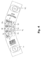
- Fig. 4 the user interface means of the handpiece is shown unfolded.
- the user interface means comprise two push buttons 81, 82 and nine light emitting diodes arranged in three rows, each row comprising three diodes.
- Each row is used to indicate selection of a parameter value of a corresponding parameter type.
- the row comprising diodes 83, 84, and 85 indicates selection of shape of the scan pattern.
- Diode 83 is turned on when a rectangular scan pattern is selected
- diode 84 is turned on when a quadratic or square scan pattern is selected
- diode 85 is turned on when a line scan pattern is selected.
- Figs. 5a - c three different scan patterns are shown according to the preferred embodiment of the invention described in these examples.
- the distance from the handpiece to the scan area is 28 mm and the spot size is 3.7 mm.
- the full scan area is 10 mm x 10 mm plus 3.7 mm spot size, thus the effective scan area is 13.7 mm x 13.7 mm (1,877 cm 2 ). If the square scan is selected there will be 23 treating spots 14, distributed in 5 lines in the scan area as seen in Fig. 5a, if the scan is rectangular there will be 14 treating spots, distributed in three lines in the scan area as seen in Fig. 5b, and if the line scan is selected there will be 5 treating spots in one line in the scan area as seen in Fig. 5c.
- the distance from the handpiece to the scan area is 58 mm and the spot size is 4 mm.
- the scan area is then 14,5 mm x 16 mm + 4 mm spot size, thus the effective scan area is 18,5 mm x 20 mm (3,7 cm 2 ). If the square scan is selected there is 39 treating spots, distributed in 7 lines, in the scan area, if the scan is rectangular there is17 treating spots, distributed in three lines, in the scan area, and if the line scan is selected there is 5 treating spots in one line in the scan area.
- the row comprising diodes 86. 87, and 88 indicates energy density or fluence.
- One or more diodes may be turned on at the same time indicating that the values of the lit diodes are to be added to provide the output fluence.
- the selection of the energy density implies a selection of the treatment time.
- diode 86 is turned on when 20 J/cm 2 and a treatment time of 26 ms is selected
- diode 87 is turned on when 30 J/cm 2 and a treatment time of 39 ms is selected
- diode 88 is turned on when 40 J/cm 2 and a treatment time of 52 ms is selected
- further diodes 86 and 87 are turned on when 50 J/cm 2 and a treatment time of 65 ms is selected
- diodes 86. 87 and 88 are turned on when 90 J/cm 2 and a treatment time of 117 ms is selected, etc.
- the row comprising diodes 89, 90, and 91 indicates additional energy density or fluence, so that the value(s) of the lit diode(s) in this row are to be added to the value(s) of any of the lit diodes 86, 87 and 88. If diode 86 is turned on and further diode 90 is turned on a fluence of 26 J/cm 2 (20 + 6 J/cm 2 ) and a treatment time of 34 ms (26 + 8 ms) is selected, etc. It is thus possible to select any fluence from 20 J/cm 2 to 108 J/cm 2 in steps of 3 J/cm 2 with the treatment times ranging from 26 ms to 141 ms.
- Depression of the push bottom 82 causes one of the light diodes to start flashing in one row indicating that parameter values of the type corresponding to that row can be selected.
- a light diode in another row will start flashing and thus, by repeatedly depressing push button 82, parameter values of each type indicated by the user interface means may be selected.
- the desired parameter value may be selected by depressing the push bottom 81 until the diode indicating selection of the desired parameter value is flashing.
- selection of scan area parameter values of the handpiece and energy densities of the light beam may be done immediately prior to scanning of the treatment area. Selection is very simple and does not require utilisation of an external computer for programming of desired scan patterns.
- the different scan pattern parameter values are stored in the memory of the handpiece. This provides an easy to learn and understand user interface requiring a minimum of teaching of the operator. Furthermore, the weight of the cables and thereby of the handpiece is reduced because there is no need for cables connecting the handpiece to an external controller. Further, by storing scan pattern parameters in the memory of the handpiece, costs for an expensive programming device is avoided. Other scan patterns than the ones described above may be downloaded to the memory of the handpiece through its computer interface. When the desired scan patterns have been downloaded, the computer interface can be disconnected from the scan pattern parameter value source and the handpiece will be ready for use.
- the processor is interfaced with the laser unit, the light emitting diodes and the two push buttons of the user interface means.
- Other interface means positioned at the handpiece may be provided where other parameters may be chosen.
- other treatment area shapes and treatment area sizes may be chosen, and furthermore, instead of choosing specific fluence values and corresponding treatment times specific laser programs may be chosen.
- the light diodes 86-91 may thus indicate selection of different laser programs, wherein each laser program contains a specific profile comprising for example wavelength, output power, energy density, treatment time or active time, spot treatment time, duty cycle, pulse width, inter pulse delay, etc, each program being designed to treatment of specific tissue profiles.
- each laser program contains a specific profile comprising for example wavelength, output power, energy density, treatment time or active time, spot treatment time, duty cycle, pulse width, inter pulse delay, etc, each program being designed to treatment of specific tissue profiles.
- the operator may select a known program having optimal settings for the specific tissue type to be treated.
- each program may be displayed on a display, such as a display provided at the laser, an external display, a display positioned on the handpiece, etc.
- the program files may be stored in the memory of the handpiece or alternatively they may be stored in a memory positioned in the laser unit.
- Fig. 6 a flow chart illustrates processor operation before the treatment scan is started.
- step 95 the processor is initialised.
- step 96 the processor checks if the handpiece is in a service mode. If so, the bus IIC, which reads and writes the outputs from the two interface integrated circuits IC11 and IC12 is disabled in step 97 as described further in the next section. If not, in step 98 activation of the push buttons of the user interface means are detected and the light emitting diodes are turned on and off accordingly as previously described. In step 99, the parameter value selections are recorded and the corresponding scan pattern and fluence settings are selected. In step 101, the processor checks if the foot pedal is depressed or activated.
- step 102 the processor gets data from the memory of the handpiece, the EEPROM, and starts the treatment scan in step 103. If not, the processor gets data from the EEPROM in step 104 and perform a guide scan in step 105, i.e. the visible light beam, traverses the circumference of the scan pattern or a part thereof as previously described. Hereafter the process is repeated from step 98.
- the visible light beam is for example a light beam with a wavelength of 635 nm and a 5 mW output power.
- the processor may be set in repeat mode so that the operator can treat a number of treatment areas without releasing the foot pedal. A delay is then inserted after the accomplishment of each treatment scan so as to allow the operator to move the handpiece to a new treatment position.
- a trained operator may only need a short delay such as a 1 second delay, but also a medium delay of 1.5 seconds and a long delay of 2 seconds may be selected. It is preferred that the operator allow the treatment area to cool down just after treatment before the handpiece with the cooling tip is removed from treatment area. This may take a few hundred milliseconds.
- an external unit may take over the control of the handpiece from the handpiece processor by taking control of the serial IIC bus.
- the handpiece processor checks whether an external computer is connected to the bus and if so control of the bus is transferred to the external computer. This may be useful when testing and adjusting the handpiece and when reprogramming the scanner.
- a flow chart illustrates a processor interrupt. This interrupt is executed every 297,5 microseconds and is set up during start up of the scanning sequence, and the set up information comprises information concerning the size, area, intensity, and velocity of the scan.
- the processor checks whether one of the push buttons has been activated, and it reads in the table of the EEPROM the next position of the treatment beam and commands the moving means to the next position.
- the first step 107 is debounce control of the buttons. Each time a signal from a push button is received, the signal is checked for 20 ms to avoid noise. The buttons are checked during start up and during guide scanning but during treatment scanning only the pedal is checked.
- step 108 the actuator is controlled according to the set up information and stepped as required.
- step 109 the galvanometer is controlled and the current regulating the movements of the galvanometer is controlled. Further, in step 110 the fading or intensity of the beam is controlled according to the set up information. The interrupt is ended in step 111.
- Fig. 8 and Fig. 9 show the electric diagrams depicting the operations of the processor IC2, e.g. a 87C752 from Philips, at the controller board 120, the galvanometer M2 at the galvanometer board 123, the linear actuator M1, the push buttons and the light emitting diodes D8 - D13 and D15 - D17 at the display board 121 and the interconnections there between.
- the processor IC2 e.g. a 87C752 from Philips
- the processor IC2 is positioned in the handpiece and the voltage is supplied from the laser unit, e.g. a Uni-laser 450P main unit.
- the processor IC2 calculates the movements of the galvanometer M2 and of the linear actuator M1 from the selected treatment parameters (area, size and time).
- a IIC bus (not shown) is connecting the processor IC2 with the two interface integrated circuits IC11 and IC12. which may be PCF8574T from Philips.
- the only parameters to be selected from the laser unit is the power, the pulses and the frequencies.
- the parameters chosen from the user interface e.g. maximum scan time, intensity, scan size, and scan shape, are stored in an EEPROM, e.g. a PCD8598D2T from Philips, where each parameter is stored in a record, which is readable from the processor IC2.
- EEPROM IC13 also off-set values for the actuator and the galvanometer are stored.
- the parameters of the laser unit may also be selected from the handpiece by the selection of pre-stored programs.
- the processor IC2 ensures that the scan is limited by the maximum treatment time chosen, and ensures that only one complete scan is performed when the pedal is activated.
- pin 8 at connector CN4 is high and the deflecting means are positioned to proper start positions by means of the connector CN11 to the galvanometer board BD3 and the connector CN3 to the actuator M1.
- the processor IC2 starts the laser unit without enabling the laser output IC8b.
- the processor IC2 receives the signal 'Laser Active' from input IC8e, the processor IC2 starts to move the galvanometer M2 and the linear actuator M1, and when these reach the proper positions the output power of the laser unit is enabled IC8a.
- the mirrors are still moved, output IC8a.
- the processor IC2 stops the laser unit, that is output IC8b is low.
- the pedal is released the laser unit will still be ready for treatment, and by moving to an adjacent area and depressing the pedal a large area may be treated.
Landscapes
- Physics & Mathematics (AREA)
- Health & Medical Sciences (AREA)
- Surgery (AREA)
- Optics & Photonics (AREA)
- Life Sciences & Earth Sciences (AREA)
- Heart & Thoracic Surgery (AREA)
- Molecular Biology (AREA)
- Nuclear Medicine, Radiotherapy & Molecular Imaging (AREA)
- Engineering & Computer Science (AREA)
- Biomedical Technology (AREA)
- Electromagnetism (AREA)
- Medical Informatics (AREA)
- Otolaryngology (AREA)
- Animal Behavior & Ethology (AREA)
- General Health & Medical Sciences (AREA)
- Public Health (AREA)
- Veterinary Medicine (AREA)
- Laser Surgery Devices (AREA)
- Radiation-Therapy Devices (AREA)
- Materials For Medical Uses (AREA)
- Processing Of Meat And Fish (AREA)
Abstract
Description
Claims (26)
- An apparatus for tissue treatment, comprisingcharacterised in thata light emitter for emission of a continuous first light beam,movable first deflecting means (39) for deflection of the first light beam into a treating light beam,an output (10) for continuous emission of the treating light beam towards a target surface (12) and illuminating a spot (14) on the target surface (12),first moving means (26, 29, 46, 47) for moving the first deflecting means (39), andfirst deflecting control means for controlling the first moving means (26, 29, 46, 47) and being adapted to control the first moving means (26, 29, 46, 47) so that the treating light beam traverses a target surface area (12) stepwise,the first deflecting means are adapted to control the first moving means so that the treating light beam traverses a target surface area (12) stepwise with steps that are greater than half the diameter of the spot (14), and not larger than substantially the diameter of the spot (14), and in such a way that the spot treatment time at a specific treatment position is between 100 ms and 1 s.
- An apparatus according to claim 1, wherein the step size is substantially equal to two thirds the diameter of the spot (14).
- An apparatus according to claim 1 or 2, wherein the first deflecting control means are adapted to control the first moving means (26, 29, 46, 47) so that the treating light beam traverses a target surface area (12) stepwise, sequentially line by line.
- An apparatus according to claim 3, wherein the first deflecting control means are adapted to control the first moving means (26, 29, 46, 47) so that the treating light beam traverses a target surface area (12) stepwise, sequentially line by line, without interlacing.
- An apparatus according to claim 4, wherein the first deflecting control means are adapted to control the first moving means (26, 29, 46, 47) so that the treating light beam traverses a target surface area (12) stepwise sequentially line by line in same directions.
- An apparatus according to any of the preceding claims, wherein the spot size ranges from 1 to 9 mm.
- An apparatus according to claim 6, wherein the spot size is approximately 4 mm.
- An apparatus according to any of the preceding claims, wherein the first deflecting means (39) comprise a first mirror (24).
- An apparatus according to claim 8, wherein the first deflecting means (39) further comprise a second mirror (25).
- An apparatus according to any of the preceding claims, further comprising light switching means for preventing emission of the treating light beam and light switching control means for controlling the light switching means.
- An apparatus for tissue treatment according to any of the preceding claims, further comprisinga handpiece (38) comprisingthe first deflecting means (39),the first deflecting control meansthe output (10), andan input connector (20) for connection of a first beam-outlet end of a first optical fibre (2) to the handpiece (38) and for alignment of the first optical fibre (2) with an axis of the handpiece (38) so that a first light beam emitted from the first beam-outlet end is transmitted substantially along the axis,a light emitter for continuous emission of the first light beam, and the first optical fibre (2) for transmission of the first light beam.
- An apparatus according to any of the preceding claims, wherein the light emitter is adapted to emit light of a wavelength larger than 190 nm.
- An apparatus according to claim 12, wherein the light emitter is adapted to emit light of a wavelength less than 3000 nm.
- An apparatus according to claim 13, wherein the light emitter is adapted to emit light of a wavelength that is substantially equal to 810 nm.
- An apparatus according to any of the preceding claims, wherein the light emitter is a laser that is adapted to emit laser light of an output power that is less than 250 W.
- An apparatus according to claim 15,wherein the laser is adapted to emit light of an output power that is less that 150 W.
- A handpiece (38) for an apparatus for tissue treatment, comprisingcharacterised in thatan input connector (29) for connection of a first beam-outlet end of a first optical fibre (2) to the handpiece (38) and for alignment of the first optical fibre (2) with an axis of the handpiece (38) so that a first light beam emitted from the first beam-outlet end is transmitted substantially along the axis,movable first deflecting means (39) for deflection of the first light beam into a treating light beam,an output (10) for continuous emission of the treating light beam towards a target surface (12) and illuminating a spot (14) on the target surface (12),first moving means (26, 29, 46, 47) for moving the first deflecting means (39), andfirst deflecting control means for controlling the first moving means (26, 29, 46, 47) and being adapted to control the first moving means (26, 29, 46, 47) so that the treating light beam traverses a target surface area (12) stepwise,the first deflecting control means are adapted to control the first moving means so that the treating light beam traverses a target surface area (12) stepwise with steps that are greater than half the diameter of the spot (14), and not larger than substantially the diameter of the spot (14), and in such a way that the spot treatment time at a specific treatment position is between 100 ms and 1 s.
- A handpiece (38) according to claim 17, wherein the step size is substantially equal to two thirds the diameter of the spot (14).
- A handpiece (38) according to claim 17 or 18, wherein the first deflecting control means are adapted to control the first moving means (26, 29, 46, 47) so that the treating light beam traverses a target surface area (12) stepwise, sequentially line by line.
- A handpiece (38) according to claim 19, wherein the first deflecting control means are adapted to control the first moving means (26, 29, 46, 47) so that the treating light beam traverses a target surface area (12) stepwise, sequentially line by line, without interlacing.
- A handpiece (38) according to claim 20, wherein the first deflecting control means are adapted to control the first moving means (26, 29, 46, 47) so that the treating light beam traverses a target surface area (12) stepwise sequentially line by line in the same direction.
- A handpiece (38) according to any of claims 17-21, wherein the spot size ranges from 1 to 9 mm.
- A handpiece (38) according to claim 22, wherein the spot size is approximately 4 mm.
- A handpiece (38) according to any of claims 17-23, wherein the first deflecting means (39) comprise a first mirror (24).
- A handpiece (38) according to claim 24, wherein the first deflecting means (39) further comprise a second mirror (25).
- A handpiece (38) according to any of claims 17-25, further comprising light switching means for preventing emission of the treating light beam and light switching control means for controlling the light switching means.
Applications Claiming Priority (5)
| Application Number | Priority Date | Filing Date | Title |
|---|---|---|---|
| US27255399A | 1999-03-19 | 1999-03-19 | |
| DK38999 | 1999-03-19 | ||
| US272553 | 1999-03-19 | ||
| DKPA199900389 | 1999-03-19 | ||
| PCT/DK2000/000131 WO2000056240A1 (en) | 1999-03-19 | 2000-03-20 | An apparatus for tissue treatment |
Publications (2)
| Publication Number | Publication Date |
|---|---|
| EP1168973A1 EP1168973A1 (en) | 2002-01-09 |
| EP1168973B1 true EP1168973B1 (en) | 2005-10-26 |
Family
ID=26063903
Family Applications (1)
| Application Number | Title | Priority Date | Filing Date |
|---|---|---|---|
| EP00910587A Expired - Lifetime EP1168973B1 (en) | 1999-03-19 | 2000-03-20 | An apparatus for tissue treatment |
Country Status (6)
| Country | Link |
|---|---|
| US (1) | US6607523B1 (en) |
| EP (1) | EP1168973B1 (en) |
| AT (1) | ATE307537T1 (en) |
| AU (1) | AU3274900A (en) |
| DE (1) | DE60023475T2 (en) |
| WO (1) | WO2000056240A1 (en) |
Families Citing this family (23)
| Publication number | Priority date | Publication date | Assignee | Title |
|---|---|---|---|---|
| US6059820A (en) | 1998-10-16 | 2000-05-09 | Paradigm Medical Corporation | Tissue cooling rod for laser surgery |
| US7041094B2 (en) * | 1999-03-15 | 2006-05-09 | Cutera, Inc. | Tissue treatment device and method |
| US7214222B2 (en) | 2001-01-29 | 2007-05-08 | Ya-Man Ltd. | Laser depilating method and laser depilating apparatus |
| US20030216719A1 (en) * | 2001-12-12 | 2003-11-20 | Len Debenedictis | Method and apparatus for treating skin using patterns of optical energy |
| EP1613202B1 (en) | 2003-03-27 | 2011-02-09 | The General Hospital Corporation | Apparatus for dermatological treatment and fractional skin resurfacing |
| US7090670B2 (en) * | 2003-12-31 | 2006-08-15 | Reliant Technologies, Inc. | Multi-spot laser surgical apparatus and method |
| CA2519553A1 (en) * | 2004-02-20 | 2005-09-01 | Francisco Javier Arcusa Villacampa | Equipment for reducing and/or removing wrinkles in the skin and method thereof |
| US7413572B2 (en) | 2004-06-14 | 2008-08-19 | Reliant Technologies, Inc. | Adaptive control of optical pulses for laser medicine |
| CA2522451A1 (en) * | 2004-10-12 | 2006-04-12 | Dectronique (1984) Inc. | Electro-epilation method |
| EP1933752A1 (en) * | 2005-04-18 | 2008-06-25 | Pantec Biosolutions AG | Microporator for creating a permeation surface |
| WO2006111201A1 (en) | 2005-04-18 | 2006-10-26 | Pantec Biosolutions Ag | Laser microporator |
| WO2007073024A2 (en) | 2005-12-23 | 2007-06-28 | Max Engineering Ltd. | Method of curing inflammatory acne by using carbon lotion and pulsed laser |
| US7891362B2 (en) * | 2005-12-23 | 2011-02-22 | Candela Corporation | Methods for treating pigmentary and vascular abnormalities in a dermal region |
| US8540703B2 (en) | 2005-12-23 | 2013-09-24 | Lutronic Corporation | Methods for treating skin conditions using laser |
| WO2007095183A2 (en) * | 2006-02-13 | 2007-08-23 | Reliant Technologies, Inc. | Laser system for treatment of skin laxity |
| KR100742973B1 (en) * | 2006-02-22 | 2007-07-27 | 주식회사 루트로닉 | Fatty tissue removing using 1444nm beam oscillating nd:yag laser |
| KR100649890B1 (en) * | 2006-03-27 | 2006-11-28 | 주식회사 루트로닉 | Control method and control structure of laser beam irradiation by using a contact sensor |
| GB2439286B (en) * | 2006-06-22 | 2010-09-15 | Dezac Group Ltd | Apparatus and methods for skin treatment |
| US20090069795A1 (en) * | 2007-09-10 | 2009-03-12 | Anderson Robert S | Apparatus and method for selective treatment of tissue |
| MX2011002987A (en) * | 2008-09-21 | 2011-07-20 | Syneron Medical Ltd | A method and apparatus for personal skin treatment. |
| ES2395575B1 (en) * | 2011-06-28 | 2013-12-20 | No Mas Vello, S.L. | BRUSHED SKIN PHOTODEPILATION SYSTEM. |
| US10799292B2 (en) | 2018-05-04 | 2020-10-13 | Bin Rao | High power tunable optical parametric oscillator for selective photothermolysis laser surgeries |
| CN108744302A (en) * | 2018-07-05 | 2018-11-06 | 深圳市三时光科技有限公司 | A kind of laser wrinkle removing beauty instrument |
Family Cites Families (69)
| Publication number | Priority date | Publication date | Assignee | Title |
|---|---|---|---|---|
| IL46832A (en) | 1975-03-14 | 1977-05-31 | Laser Ind Ltd | Device for aligning an invisible beam particularly a laser beam |
| US4387952A (en) | 1981-03-27 | 1983-06-14 | Spectra-Physics, Inc. | Single axis beam scanner |
| CA1223644A (en) | 1981-09-24 | 1987-06-30 | James R. Morris | Microsurgical laser |
| IL67599A (en) | 1982-12-31 | 1986-09-30 | Laser Ind Ltd | Control apparatus particularly useful for controlling a laser |
| US4665913A (en) | 1983-11-17 | 1987-05-19 | Lri L.P. | Method for ophthalmological surgery |
| JPS60148566A (en) | 1984-01-13 | 1985-08-05 | 株式会社東芝 | Laser treatment apparatus |
| IL75998A0 (en) | 1984-08-07 | 1985-12-31 | Medical Laser Research & Dev C | Laser system for providing target tissue specific energy deposition |
| US5336217A (en) * | 1986-04-24 | 1994-08-09 | Institut National De La Sante Et De La Recherche Medicale (Insepm) | Process for treatment by irradiating an area of a body, and treatment apparatus usable in dermatology for the treatment of cutaneous angio dysplasias |
| US4923263A (en) | 1988-09-22 | 1990-05-08 | The United States Of America As Represented By The Secretary Of The Army | Rotating mirror optical scanning device |
| DE3837248A1 (en) | 1988-10-28 | 1990-05-03 | Teichmann Heinrich Otto Dr Phy | Device for treating skin lesions |
| US5048904A (en) | 1990-07-06 | 1991-09-17 | General Scanning, Inc. | Two-mirror scanner with pincushion error correction |
| JP3168207B2 (en) | 1990-08-22 | 2001-05-21 | ヴィスクス・インコーポレイテッド | Surgical laser beam scanning device |
| US5128509A (en) | 1990-09-04 | 1992-07-07 | Reliant Laser Corp. | Method and apparatus for transforming and steering laser beams |
| US5065515A (en) | 1991-01-24 | 1991-11-19 | Warner-Lambert Company | Thermally assisted shaving system |
| US5178617A (en) | 1991-07-09 | 1993-01-12 | Laserscope | System for controlled distribution of laser dosage |
| US5474549A (en) | 1991-07-09 | 1995-12-12 | Laserscope | Method and system for scanning a laser beam for controlled distribution of laser dosage |
| US5871480A (en) | 1991-10-29 | 1999-02-16 | Thermolase Corporation | Hair removal using photosensitizer and laser |
| US5817089A (en) | 1991-10-29 | 1998-10-06 | Thermolase Corporation | Skin treatment process using laser |
| JPH07503382A (en) * | 1991-11-06 | 1995-04-13 | ライ,シュイ,ティー. | Corneal surgery device and method |
| IL100664A0 (en) | 1992-01-15 | 1992-09-06 | Laser Ind Ltd | Method and apparatus for controlling a laser beam |
| US5405368A (en) | 1992-10-20 | 1995-04-11 | Esc Inc. | Method and apparatus for therapeutic electromagnetic treatment |
| US5620478A (en) | 1992-10-20 | 1997-04-15 | Esc Medical Systems Ltd. | Method and apparatus for therapeutic electromagnetic treatment |
| DE4238456A1 (en) | 1992-11-13 | 1994-05-19 | Nwl Laser Tech Gmbh | Process for the action on hair for cosmetic purposes |
| US5520679A (en) | 1992-12-03 | 1996-05-28 | Lasersight, Inc. | Ophthalmic surgery method using non-contact scanning laser |
| US5382770A (en) | 1993-01-14 | 1995-01-17 | Reliant Laser Corporation | Mirror-based laser-processing system with visual tracking and position control of a moving laser spot |
| US5860967A (en) | 1993-07-21 | 1999-01-19 | Lucid, Inc. | Dermatological laser treatment system with electronic visualization of the area being treated |
| US5397327A (en) | 1993-07-27 | 1995-03-14 | Coherent, Inc. | Surgical laser handpiece for slit incisions |
| IL108059A (en) | 1993-12-17 | 1998-02-22 | Laser Ind Ltd | Method and apparatus for applying laser beams to a working surface, particularly for ablating tissue |
| US5628744A (en) | 1993-12-21 | 1997-05-13 | Laserscope | Treatment beam handpiece |
| WO1995018984A1 (en) | 1994-01-07 | 1995-07-13 | Coherent, Inc. | Apparatus for creating a square or rectangular laser beam with a uniform intensity profile |
| CA2131750C (en) | 1994-07-26 | 2000-11-21 | Nikolai I. Tankovich | Improved hair removal method |
| US5743902A (en) | 1995-01-23 | 1998-04-28 | Coherent, Inc. | Hand-held laser scanner |
| US5735844A (en) | 1995-02-01 | 1998-04-07 | The General Hospital Corporation | Hair removal using optical pulses |
| US5611795A (en) | 1995-02-03 | 1997-03-18 | Laser Industries, Ltd. | Laser facial rejuvenation |
| RU2096051C1 (en) | 1995-02-24 | 1997-11-20 | Григорий Борисович Альтшулер | Apparatus for laser treatment of biological tissues (alternative embodiments) |
| US5868731A (en) | 1996-03-04 | 1999-02-09 | Innotech Usa, Inc. | Laser surgical device and method of its use |
| US5735276A (en) | 1995-03-21 | 1998-04-07 | Lemelson; Jerome | Method and apparatus for scanning and evaluating matter |
| US5885273A (en) | 1995-03-29 | 1999-03-23 | Esc Medical Systems, Ltd. | Method for depilation using pulsed electromagnetic radiation |
| US5546214A (en) | 1995-09-13 | 1996-08-13 | Reliant Technologies, Inc. | Method and apparatus for treating a surface with a scanning laser beam having an improved intensity cross-section |
| IL115477A0 (en) | 1995-10-01 | 1996-01-19 | Kaplan Harel Holdings Ltd | Scanner |
| US5860968A (en) | 1995-11-03 | 1999-01-19 | Luxar Corporation | Laser scanning method and apparatus |
| US6033396A (en) * | 1995-11-06 | 2000-03-07 | Huang; David | Apparatus and method for performing laser thermal keratoplasty with minimized regression |
| US5879346A (en) | 1995-12-18 | 1999-03-09 | Esc Medical Systems, Ltd. | Hair removal by selective photothermolysis with an alexandrite laser |
| GB9602375D0 (en) * | 1996-02-06 | 1996-04-03 | Jones Gary L | Laser depilation apparatus and method |
| US5630811A (en) | 1996-03-25 | 1997-05-20 | Miller; Iain D. | Method and apparatus for hair removal |
| US5871479A (en) | 1996-11-07 | 1999-02-16 | Cynosure, Inc. | Alexandrite laser system for hair removal and method therefor |
| JP3036232U (en) | 1996-09-26 | 1997-04-15 | ヤーマン株式会社 | Optical hair removal device |
| WO1998025528A1 (en) * | 1996-12-10 | 1998-06-18 | Asah Medico A/S | An apparatus for cosmetic tissue treatment |
| US5938657A (en) | 1997-02-05 | 1999-08-17 | Sahar Technologies, Inc. | Apparatus for delivering energy within continuous outline |
| US5906609A (en) | 1997-02-05 | 1999-05-25 | Sahar Technologies | Method for delivering energy within continuous outline |
| IL120811A0 (en) | 1997-05-08 | 1997-09-30 | Laser Ind Ltd | Method and apparatus for performing transmyocardial revascularization |
| US6235015B1 (en) | 1997-05-14 | 2001-05-22 | Applied Optronics Corporation | Method and apparatus for selective hair depilation using a scanned beam of light at 600 to 1000 nm |
| EP0991372B1 (en) | 1997-05-15 | 2004-08-04 | Palomar Medical Technologies, Inc. | Apparatus for dermatology treatment |
| GB9710562D0 (en) | 1997-05-23 | 1997-07-16 | Medical Laser Technologies Lim | Light delivery |
| DE69812725T2 (en) | 1997-05-30 | 2003-10-09 | Nidek Kk | Laser treatment apparatus |
| US5865828A (en) | 1997-08-08 | 1999-02-02 | Jeng; James C. | Coaxial dual laser |
| US6168590B1 (en) | 1997-08-12 | 2001-01-02 | Y-Beam Technologies, Inc. | Method for permanent hair removal |
| JPH1170121A (en) | 1997-08-29 | 1999-03-16 | Nidek Co Ltd | Laser treatment device |
| US6074382A (en) | 1997-08-29 | 2000-06-13 | Asah Medico A/S | Apparatus for tissue treatment |
| US6176854B1 (en) | 1997-10-08 | 2001-01-23 | Robert Roy Cone | Percutaneous laser treatment |
| CA2305721C (en) | 1997-10-08 | 2009-02-24 | The General Hospital Corporation | Phototherapy methods and systems |
| US5984915A (en) | 1997-10-08 | 1999-11-16 | Trimedyne, Inc. | Percutaneous laser treatment |
| WO1999027997A1 (en) | 1997-12-01 | 1999-06-10 | Esc Medical Systems Ltd. | Improved depilatory method and device |
| WO1999032193A1 (en) | 1997-12-23 | 1999-07-01 | Esc Medical Systems Ltd. | Apparatus for therapeutic electromagnetic treatment |
| US6066129A (en) | 1998-01-29 | 2000-05-23 | Larson; Dean W. | Medical laser control system |
| US6080146A (en) | 1998-02-24 | 2000-06-27 | Altshuler; Gregory | Method and apparatus for hair removal |
| US6030378A (en) | 1998-05-26 | 2000-02-29 | Stewart; Bob W. | Method of hair removal by transcutaneous application of laser light |
| US6110195A (en) | 1998-06-01 | 2000-08-29 | Altralight, Inc. | Method and apparatus for surgical and dermatological treatment by multi-wavelength laser light |
| US6514242B1 (en) | 1998-12-03 | 2003-02-04 | David Vasily | Method and apparatus for laser removal of hair |
-
2000
- 2000-03-20 EP EP00910587A patent/EP1168973B1/en not_active Expired - Lifetime
- 2000-03-20 AT AT00910587T patent/ATE307537T1/en not_active IP Right Cessation
- 2000-03-20 DE DE60023475T patent/DE60023475T2/en not_active Expired - Lifetime
- 2000-03-20 AU AU32749/00A patent/AU3274900A/en not_active Abandoned
- 2000-03-20 WO PCT/DK2000/000131 patent/WO2000056240A1/en active IP Right Grant
- 2000-03-20 US US09/936,328 patent/US6607523B1/en not_active Expired - Lifetime
Also Published As
| Publication number | Publication date |
|---|---|
| ATE307537T1 (en) | 2005-11-15 |
| AU3274900A (en) | 2000-10-09 |
| DE60023475D1 (en) | 2005-12-01 |
| US6607523B1 (en) | 2003-08-19 |
| EP1168973A1 (en) | 2002-01-09 |
| DE60023475T2 (en) | 2006-07-20 |
| WO2000056240A1 (en) | 2000-09-28 |
Similar Documents
| Publication | Publication Date | Title |
|---|---|---|
| EP1168973B1 (en) | An apparatus for tissue treatment | |
| US6190376B1 (en) | Apparatus for tissue treatment | |
| US6676654B1 (en) | Apparatus for tissue treatment and having a monitor for display of tissue features | |
| US6383177B1 (en) | Apparatus for tissue treatment | |
| US6533774B1 (en) | Laser depilation apparatus | |
| US6579283B1 (en) | Apparatus and method employing a single laser for removal of hair, veins and capillaries | |
| US6149645A (en) | Apparatus and method employing lasers for removal of hair | |
| JP5153618B2 (en) | Hair growth control device and hair growth control method | |
| US5653706A (en) | Dermatological laser treatment system with electronic visualization of the area being treated | |
| US6951558B2 (en) | Scanning laser handpiece with shaped output beam | |
| US20060276778A1 (en) | Multi-Spot Laser Surgical Apparatus and Method | |
| US6887233B2 (en) | Scanning laser handpiece with shaped output beam | |
| US6585725B1 (en) | Laser irradiation method for laser treatment and laser treatment apparatus | |
| AU2005268431A1 (en) | Optical scanning device | |
| US6168589B1 (en) | Apparatus and method employing a single laser for removal of hair | |
| CN110840559A (en) | Skin pore identification and positioning depilation system based on computer vision | |
| KR20090031717A (en) | Apparatus and methods for skin treatment | |
| US6165171A (en) | Apparatus and method employing lasers for removal of hair | |
| US6217572B1 (en) | Apparatus and method employing lasers for removal of hair | |
| EP0948290B1 (en) | An apparatus for cosmetic tissue treatment | |
| US20100030201A1 (en) | Apparatus for skin treatment | |
| WO2004007023A1 (en) | A handpiece for tissue treatment | |
| JP2002172179A (en) | Apparatus and method for laser depilation | |
| CN210534436U (en) | Laser device |
Legal Events
| Date | Code | Title | Description |
|---|---|---|---|
| PUAI | Public reference made under article 153(3) epc to a published international application that has entered the european phase |
Free format text: ORIGINAL CODE: 0009012 |
|
| 17P | Request for examination filed |
Effective date: 20011019 |
|
| AK | Designated contracting states |
Kind code of ref document: A1 Designated state(s): AT BE CH CY DE DK ES FI FR GB GR IE IT LI LU MC NL PT SE |
|
| AX | Request for extension of the european patent |
Free format text: AL;LT;LV;MK;RO;SI |
|
| RIN1 | Information on inventor provided before grant (corrected) |
Inventor name: CASPER DOLLERIS Inventor name: BALLE-PETERSEN, OLAV Inventor name: ASAH, BJARNE |
|
| GRAP | Despatch of communication of intention to grant a patent |
Free format text: ORIGINAL CODE: EPIDOSNIGR1 |
|
| GRAS | Grant fee paid |
Free format text: ORIGINAL CODE: EPIDOSNIGR3 |
|
| GRAA | (expected) grant |
Free format text: ORIGINAL CODE: 0009210 |
|
| AK | Designated contracting states |
Kind code of ref document: B1 Designated state(s): AT BE CH CY DE DK ES FI FR GB GR IE IT LI LU MC NL PT SE |
|
| PG25 | Lapsed in a contracting state [announced via postgrant information from national office to epo] |
Ref country code: BE Free format text: LAPSE BECAUSE OF FAILURE TO SUBMIT A TRANSLATION OF THE DESCRIPTION OR TO PAY THE FEE WITHIN THE PRESCRIBED TIME-LIMIT Effective date: 20051026 Ref country code: LI Free format text: LAPSE BECAUSE OF FAILURE TO SUBMIT A TRANSLATION OF THE DESCRIPTION OR TO PAY THE FEE WITHIN THE PRESCRIBED TIME-LIMIT Effective date: 20051026 Ref country code: FI Free format text: LAPSE BECAUSE OF FAILURE TO SUBMIT A TRANSLATION OF THE DESCRIPTION OR TO PAY THE FEE WITHIN THE PRESCRIBED TIME-LIMIT Effective date: 20051026 Ref country code: NL Free format text: LAPSE BECAUSE OF FAILURE TO SUBMIT A TRANSLATION OF THE DESCRIPTION OR TO PAY THE FEE WITHIN THE PRESCRIBED TIME-LIMIT Effective date: 20051026 Ref country code: CH Free format text: LAPSE BECAUSE OF FAILURE TO SUBMIT A TRANSLATION OF THE DESCRIPTION OR TO PAY THE FEE WITHIN THE PRESCRIBED TIME-LIMIT Effective date: 20051026 Ref country code: AT Free format text: LAPSE BECAUSE OF FAILURE TO SUBMIT A TRANSLATION OF THE DESCRIPTION OR TO PAY THE FEE WITHIN THE PRESCRIBED TIME-LIMIT Effective date: 20051026 Ref country code: IT Free format text: LAPSE BECAUSE OF FAILURE TO SUBMIT A TRANSLATION OF THE DESCRIPTION OR TO PAY THE FEE WITHIN THE PRESCRIBED TIME-LIMIT;WARNING: LAPSES OF ITALIAN PATENTS WITH EFFECTIVE DATE BEFORE 2007 MAY HAVE OCCURRED AT ANY TIME BEFORE 2007. THE CORRECT EFFECTIVE DATE MAY BE DIFFERENT FROM THE ONE RECORDED. Effective date: 20051026 |
|
| REG | Reference to a national code |
Ref country code: GB Ref legal event code: FG4D |
|
| REG | Reference to a national code |
Ref country code: CH Ref legal event code: EP |
|
| REG | Reference to a national code |
Ref country code: IE Ref legal event code: FG4D |
|
| REF | Corresponds to: |
Ref document number: 60023475 Country of ref document: DE Date of ref document: 20051201 Kind code of ref document: P |
|
| PG25 | Lapsed in a contracting state [announced via postgrant information from national office to epo] |
Ref country code: DK Free format text: LAPSE BECAUSE OF FAILURE TO SUBMIT A TRANSLATION OF THE DESCRIPTION OR TO PAY THE FEE WITHIN THE PRESCRIBED TIME-LIMIT Effective date: 20060126 Ref country code: SE Free format text: LAPSE BECAUSE OF FAILURE TO SUBMIT A TRANSLATION OF THE DESCRIPTION OR TO PAY THE FEE WITHIN THE PRESCRIBED TIME-LIMIT Effective date: 20060126 Ref country code: GR Free format text: LAPSE BECAUSE OF FAILURE TO SUBMIT A TRANSLATION OF THE DESCRIPTION OR TO PAY THE FEE WITHIN THE PRESCRIBED TIME-LIMIT Effective date: 20060126 |
|
| PG25 | Lapsed in a contracting state [announced via postgrant information from national office to epo] |
Ref country code: ES Free format text: LAPSE BECAUSE OF FAILURE TO SUBMIT A TRANSLATION OF THE DESCRIPTION OR TO PAY THE FEE WITHIN THE PRESCRIBED TIME-LIMIT Effective date: 20060206 |
|
| PG25 | Lapsed in a contracting state [announced via postgrant information from national office to epo] |
Ref country code: IE Free format text: LAPSE BECAUSE OF NON-PAYMENT OF DUE FEES Effective date: 20060320 |
|
| PG25 | Lapsed in a contracting state [announced via postgrant information from national office to epo] |
Ref country code: PT Free format text: LAPSE BECAUSE OF FAILURE TO SUBMIT A TRANSLATION OF THE DESCRIPTION OR TO PAY THE FEE WITHIN THE PRESCRIBED TIME-LIMIT Effective date: 20060327 |
|
| PG25 | Lapsed in a contracting state [announced via postgrant information from national office to epo] |
Ref country code: LU Free format text: LAPSE BECAUSE OF NON-PAYMENT OF DUE FEES Effective date: 20060331 Ref country code: MC Free format text: LAPSE BECAUSE OF NON-PAYMENT OF DUE FEES Effective date: 20060331 |
|
| NLV1 | Nl: lapsed or annulled due to failure to fulfill the requirements of art. 29p and 29m of the patents act | ||
| REG | Reference to a national code |
Ref country code: CH Ref legal event code: PL |
|
| PLBE | No opposition filed within time limit |
Free format text: ORIGINAL CODE: 0009261 |
|
| STAA | Information on the status of an ep patent application or granted ep patent |
Free format text: STATUS: NO OPPOSITION FILED WITHIN TIME LIMIT |
|
| 26N | No opposition filed |
Effective date: 20060727 |
|
| REG | Reference to a national code |
Ref country code: IE Ref legal event code: MM4A |
|
| EN | Fr: translation not filed | ||
| PG25 | Lapsed in a contracting state [announced via postgrant information from national office to epo] |
Ref country code: FR Free format text: LAPSE BECAUSE OF FAILURE TO SUBMIT A TRANSLATION OF THE DESCRIPTION OR TO PAY THE FEE WITHIN THE PRESCRIBED TIME-LIMIT Effective date: 20061215 |
|
| PG25 | Lapsed in a contracting state [announced via postgrant information from national office to epo] |
Ref country code: CY Free format text: LAPSE BECAUSE OF FAILURE TO SUBMIT A TRANSLATION OF THE DESCRIPTION OR TO PAY THE FEE WITHIN THE PRESCRIBED TIME-LIMIT Effective date: 20051026 Ref country code: FR Free format text: LAPSE BECAUSE OF FAILURE TO SUBMIT A TRANSLATION OF THE DESCRIPTION OR TO PAY THE FEE WITHIN THE PRESCRIBED TIME-LIMIT Effective date: 20051026 |
|
| PGFP | Annual fee paid to national office [announced via postgrant information from national office to epo] |
Ref country code: GB Payment date: 20110325 Year of fee payment: 12 Ref country code: DE Payment date: 20110325 Year of fee payment: 12 |
|
| GBPC | Gb: european patent ceased through non-payment of renewal fee |
Effective date: 20120320 |
|
| REG | Reference to a national code |
Ref country code: DE Ref legal event code: R119 Ref document number: 60023475 Country of ref document: DE Effective date: 20121002 |
|
| PG25 | Lapsed in a contracting state [announced via postgrant information from national office to epo] |
Ref country code: GB Free format text: LAPSE BECAUSE OF NON-PAYMENT OF DUE FEES Effective date: 20120320 |
|
| PG25 | Lapsed in a contracting state [announced via postgrant information from national office to epo] |
Ref country code: DE Free format text: LAPSE BECAUSE OF NON-PAYMENT OF DUE FEES Effective date: 20121002 |