EP1166516B1 - Method for synchronisation - Google Patents
Method for synchronisation Download PDFInfo
- Publication number
- EP1166516B1 EP1166516B1 EP00929244A EP00929244A EP1166516B1 EP 1166516 B1 EP1166516 B1 EP 1166516B1 EP 00929244 A EP00929244 A EP 00929244A EP 00929244 A EP00929244 A EP 00929244A EP 1166516 B1 EP1166516 B1 EP 1166516B1
- Authority
- EP
- European Patent Office
- Prior art keywords
- synchronization
- communication system
- transmitter
- sequence
- receiver
- Prior art date
- Legal status (The legal status is an assumption and is not a legal conclusion. Google has not performed a legal analysis and makes no representation as to the accuracy of the status listed.)
- Expired - Lifetime
Links
Images

Classifications
-
- H—ELECTRICITY
- H04—ELECTRIC COMMUNICATION TECHNIQUE
- H04L—TRANSMISSION OF DIGITAL INFORMATION, e.g. TELEGRAPHIC COMMUNICATION
- H04L7/00—Arrangements for synchronising receiver with transmitter
-
- H—ELECTRICITY
- H04—ELECTRIC COMMUNICATION TECHNIQUE
- H04L—TRANSMISSION OF DIGITAL INFORMATION, e.g. TELEGRAPHIC COMMUNICATION
- H04L27/00—Modulated-carrier systems
- H04L27/26—Systems using multi-frequency codes
- H04L27/2601—Multicarrier modulation systems
- H04L27/2602—Signal structure
- H04L27/261—Details of reference signals
- H04L27/2613—Structure of the reference signals
- H04L27/26134—Pilot insertion in the transmitter chain, e.g. pilot overlapping with data, insertion in time or frequency domain
Landscapes
- Engineering & Computer Science (AREA)
- Computer Networks & Wireless Communication (AREA)
- Signal Processing (AREA)
- Synchronisation In Digital Transmission Systems (AREA)
- Small-Scale Networks (AREA)
Description
Die Erfindung geht aus von einem verfahren zur Synchronisation eines oder mehrerer Empfänger auf einen Sender innerhalb eines Übertragungssystems unter Verwendung eines Datenstromes mit Schutzintervallen insbesondere für den Ausgleich von Mehrwegeausbreitung sowie von einem Sender zur Aufbereitung einer Synchronisationsfolge und einem Empfänger zur Auswertung dieser Synchronisationsfolge und einem Kommunikationssystem.The invention relates to a method for synchronizing one or more receivers to a transmitter within a transmission system using a data stream with guard intervals, in particular for balancing multipath propagation, and by a transmitter for processing a synchronization sequence and a receiver for evaluating this synchronization sequence and a communication system.
Es wird beispielsweise davon ausgegangen, daß ein Sender einen oder mehrere Empfänger bedient. Der Sender sendet zu einem Zeitpunkt ein oder mehrere Pakete an die Empfänger.For example, it is assumed that a transmitter serves one or more receivers. The sender sends one or more packets to the receivers at a time.
In einem Übertragungssystem, welches insbesondere OFDM (Orthogonal Frequency Division Multiplexing) verwendet, stellt sich das Problem der Synchronisation. Bei der OFDM-Übertragung werden die Sendesymbole auf mehrere Unterträger im Frequenzbereich durch eine im allgemeinen digitale Modulationsart aufmoduliert [1]. Die Unterträger werden dann in Summe mit einer IFFT (Inverse Fast Fourier Transformation) in den Zeitbereich transformiert und anschließend ausgesendet.In a transmission system using Orthogonal Frequency Division Multiplexing (OFDM) in particular, the problem of synchronization arises. In the OFDM transmission, the transmit symbols are modulated onto a plurality of subcarriers in the frequency domain by a generally digital modulation scheme [1]. The subcarriers are then transformed in total with an IFFT (Inverse Fast Fourier Transformation) in the time domain and then sent out.
Im Empfänger ist es notwendig einige Informationen über das gesendete Signal zu rekonstruieren, insbesondere den Blockbeginn und die Frequenzablage.In the receiver, it is necessary to reconstruct some information about the transmitted signal, in particular the block start and the frequency offset.
Zur Ermittlung des Blockbeginns muß die zeitliche Lage des zu empfangenden Signals bekannt sein. Für diesen Zweck wird meist ein zweistufiges Verfahren verwendet, demgemäß zuerst eine grobe und anschließend eine feine Detektion des Blockbeginns nacheinander durchgeführt werden.To determine the start of the block, the timing of the signal to be received must be known. For this purpose, a two-stage method is usually used, according to which first a coarse and then a fine detection of the beginning of the block are carried out one after the other.
Im Normalfall hat der Empfänger eine Frequenzablage gegenüber dem Sender. Im Falle von OFDM ist diese Ablage besonders kritisch, weil es dadurch zu einer Störung der Orthogonalität kommen kann, die zu erhöhten Bitfehlern führt. Die Frequenzsynchronisation dient dazu, diese Frequenzdifferenz zu korrigieren.Normally, the receiver has a frequency offset with respect to the transmitter. In the case of OFDM, this filing is particularly critical, because it can lead to a disturbance of the orthogonality, which leads to increased bit errors. The frequency synchronization is used to correct this frequency difference.
Um in einem Kommunikationssystem mit Übertragung relativ kurzer Datenpakete eine Synchronisation zu erreichen, werden einem Übertragungsburst gemäß [2], [3] und [4] zwei identische Synchronisationssymbole, insbesondere OFDM-symbole vorangestellt, die zweimal mit einem vorgegebenen Abstand ausgesendet werden. Die Position dieser Signale kann durch Auswertung der Metrik bestimmt werden.In order to achieve synchronization in a communication system with transmission of relatively short data packets, a transmission burst in accordance with [2], [3] and [4] is preceded by two identical synchronization symbols, in particular OFDM symbols, which are transmitted twice at a predetermined distance. The position of these signals can be determined by evaluating the metric.
Zur Vermeidung von Tntersymbol-Interferenzen (ISI) wird im Zusammenhang mit der OFDM-Übertragungstechnik häufig ein Schutzintervall im Sender eingefügt, dessen Länge an die Dauer der Kanalimpulsantwort angepaßt ist. Damit im Empfänger auch tatsächlich keine Störung durch zeitlich benachbarte Symbole auftreten, muß der Einschwingzeitpunkt, das heißt der Beginn des ISI-freien Signalabschnittes, vor der Datenauswertung im Empfänger ermittelt werden. Die Ermittlung dieses Zeitpunktes wird als Block- oder Symbolsynchronisation bezeichnet. Wenn die Impulsantwort des vorliegenden Kanals kürzer ist als das Schutzintervall, muss die Blocksynchronisation nicht genau den Beginn des eingeschwungenen Zustands ermitteln, sondern es ergibt sich ein zulässiges Synchronisationsintervall.In order to avoid interference symbol interference (ISI), in connection with the OFDM transmission technique, a guard interval is often inserted in the transmitter whose length is adapted to the duration of the channel impulse response. So that in the receiver actually no interference by temporally adjacent symbols occur, the settling time, that is, the beginning of the ISI-free signal section, must be determined before the data evaluation in the receiver. The determination of this time is called block or symbol synchronization. If the impulse response of the If the present channel is shorter than the guard interval, the block synchronization does not have to determine exactly the start of the steady state, but instead results in a permissible synchronization interval.
Aus der
die
Mit den Maßnahmen gemäß Anspruch 1 lässt sich die Genauigkeit der Synchronisation gegenüber bekannten Verfahren wesentlich verbessern. Während die bekannten Verfahren eigentlich nur zu einer groben Blocksynchronisation verwendbar sind, liefert das Verfahren nach der Erfindung recht genaue Ergebnisse sowohl hinsichtlich einer feinen Block- als auch einer Frequenzschätzung. Die erfindungsgemäße Lösung eignet sich vorteilhaft für OFDM als Übertragungsverfahren. Wenn eine kohärente Demodulation vorgesehen ist, kann die Synchronisationsfolge zur Blocksynchronisation und Schätzung der Frequenzablage auch zur Schätzung der Kanalimpulsantwort verwendet werden.With the measures according to claim 1, the accuracy of the synchronization over known methods can be significantly improved. While the known methods are actually usable only for coarse block synchronization, the method according to the invention provides quite accurate results both in terms of fine block and frequency estimation. The solution according to the invention is advantageously suitable for OFDM as a transmission method. If coherent demodulation is provided, the synchronization sequence for block synchronization and frequency offset estimation can also be used to estimate the channel impulse response.
Der Implementierungsaufwand für das Verfahren nach der Erfindung ist kaum höher als bei bekannten Verfahren, liefert aber eine erhöhte Genauigkeit der Schätzung insbesondere der Frequenzablage.The implementation effort for the method according to the invention is hardly higher than in known methods, but provides an increased accuracy of the estimation, in particular the frequency offset.
Das Verfahren nach der Erfindung bzw. ein entsprechendes Kommunikationssystem eignet sich vorteilhaft zum Einsatz in Funksystemen, und zwar in normalen bidirektionalen Kommunikationssystemen mit variabler Rollenverteilung von Sender und Empfänger als auch in Rundstrahlsystemen, in denen die Rollen von Sender und Empfänger statisch über der Zeit sind.The method according to the invention or a corresponding communication system is advantageously suitable for use in radio systems, in normal bidirectional communication systems with variable role distribution of transmitter and receiver as well as in omnidirectional systems in which the roles of transmitter and receiver are static over time.
Als Übertragungsmedium kann außer Funk auch eine Ieitungsgebundene Übertragung vorgesehen sein, beispielsweise über Koaxialkabel oder über geschirmte oder ungeschirmte Adernpaare eines Leitungsnetzes. Auch in Hybridkommunikationssystemen, daß heißt mit Funkkomponenten, leitungsgebundenen Komponenten und/oder Lichtquellenleiter-Komponenten, ist die Erfindung vorteilhaft einsetzbar.As a transmission medium may be provided out of radio and an on-line transmission, For example via coaxial cable or over shielded or unshielded wire pairs of a network. Also in hybrid communication systems, that is with radio components, line-bound components and / or light source conductor components, the invention can be used advantageously.
Als Modulationsart eignet sich insbesondere OFDM. Aber auch in Systemen ohne OFDM, wo Übertragungsverfahren verwendet werden, in denen ein Schutzintervall für den Ausgleich von Mehrwegeausbreitung vorgesehen ist, kann die Erfindung vorteilhaft zum Einsatz kommen.The modulation type is in particular OFDM. But even in systems without OFDM, where transmission methods are used, in which a guard interval for the compensation of multipath propagation is provided, the invention can be used advantageously.
Anhand der Zeichnungen werden Ausführungsbeispiele näher erläutert. Es zeigen:
-
Figur 1 ein Funknetz mit einem Sender und mehreren Empfängern, -
Figur 2 den Aufbau einer Synchronisationsfolge nach dem Stand der Technik, -
Figur 3 den Aufbau einer Synchrcnisationsfolge nach der Erfindung, -
Figur 4 den Aufbau einer Synchronisationsfolge mit Präambel, -
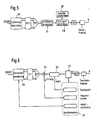
Figur 5 ein Blockschaltbild eines Senders nach der Erfindung, -
Figur 6 ein Blockschaltbild eines Empfängers nach der Erfindung.
-
FIG. 1 a radio network with one transmitter and several receivers, -
FIG. 2 the construction of a synchronization sequence according to the prior art, -
FIG. 3 the construction of a synchronization sequence according to the invention, -
FIG. 4 the construction of a synchronization sequence with preamble, -
FIG. 5 a block diagram of a transmitter according to the invention, -
FIG. 6 a block diagram of a receiver according to the invention.
Bevor auf die eigentliche erfindungsgemäße Realisierung eingegangen wird, wird zum besseren Verständnis die Synchronisation nach dem Stand der Technik erläutert.Before discussing the actual implementation according to the invention, the synchronization according to the prior art will be explained for a better understanding.
Es wird für die folgenden Betrachtungen davon ausgegangen, daß gemäß
Der Sender S eines Teilnehmers sendet im Moment ein oder mehrere Datenpakte an die Empfänger E1, E2, E3, deren Dauer konstant oder variabel sein kann. Die Situation kann sich allgemein auch derart ändern, daß dynamisch einer der Teilnehmer vom Empfangsbetrieb später auf Sendebetrieb umschaltet und ein sendender Teilnehmer und/oder die anderen empfangenden Teilnehmer dann im Empfangsbetrieb arbeiten.The sender S of a subscriber currently sends one or more data packets to the receivers E1, E2, E3, whose duration may be constant or variable. The situation can generally also change such that dynamically one of the subscribers switches later from the receive mode to transmit mode and a transmitting subscriber and / or the other receiving subscriber then work in receive mode.
Es wird weiter davon ausgegangen, daß als Übertragungsverfahren OFDM verwendet wird, vergleiche [1], [3], [4]. Dazu werden die Sendeymbole auf mehrere Unterträger im Frequenzbereich durch eine im allgemeinen digitale Modulationsart aufmoduliert. Die Unterträger werden dann in Summe mit einer IFFT (Inverse Fast Fourier Transformation) in den Zeitbereich transformiert und anschließend ausgesendet.It is further assumed that OFDM is used as the transmission method, compare [1], [3], [4]. For this purpose, the transmit symbols are modulated onto a plurality of subcarriers in the frequency domain by a generally digital modulation type. The subcarriers are then transformed in total with an IFFT (Inverse Fast Fourier Transformation) in the time domain and then sent out.
Da in einem Kommunikationssystem nur kurze Datenpakete übertragen werden, ist eine schnelle Synchronisation dringend erforderlich. Dies ist nur mit Hilfe eines speziellen Synchronisationssymbols zu erreichen, das dem Datenpaket im Sender vorangestellt wird.Since only short data packets are transmitted in a communication system, fast synchronization is urgently required. This can only be achieved with the help of a special synchronization symbol, which precedes the data packet in the sender.
Ein bekanntes Verfahren zur Blocksynchronisation, vergleiche [2] und [3], ist die Auswertung eines Signals A = {ri } der Länge N, das zweimal mit dem Abstand P versendet wird, siehe 
bestimmt werden.A known method of block synchronization, see [2] and [3], the evaluation of a signal is A = {r i} of length N, which is sent twice with the pitch P, see
be determined.
Das Kriterium für den Blockbeginn ist gegeben durch den-Index i, bei dem die Metrik ihre minimale Phase aufweist: 
Die Blocksynchronisation im OFDM-System soll anhand der periodischen Präambel auf den interferenzfreien Bereich der folgenden Datenblöcke schließen. Dazu wird das Korrelationsfenster gegenüber der Sequenzlänge um die Länge des Schutzintervalls verkürzt.The block synchronization in the OFDM system should close on the basis of the periodic preamble on the interference-free range of the following data blocks. For this purpose, the correlation window is shortened compared to the sequence length by the length of the guard interval.
Dieses zuvor beschriebene Verfahren wird eigentlich zur groben Bloksynchronisation verwendet. Daher liefert es prinzipbedingt nur recht ungenau Ergebnisse sowohl hinsichtlich einer feinen Block- als auch Frequenzschätzung.This method described above is actually used for coarse block synchronization. Therefore, in principle, it provides only very inaccurate results both in terms of a fine block and frequency estimate.
Der Sender S gemäß
- es werden zwei verschiedene Symbolsequenzen A und B gleicher Länge L1 mit idealerweise günstigen Autokorrelations-Eigenschaften ausgewählt. Im Falle von OFDM können dies OFDM-Symbole sein, die die gleiche oder verschiedene Länge wie ein normales Datensymbol haben,
- die beiden Symbolsequenzen A und B werden immer so ausgesendet, das abwechselnd zweimal A und zweimal B ausgesendet wird, gemäß
Figur 3 . Die Indizes bei den Symbolsequenzen A und B bezeichnen dabei das Auftreten der Folgen A und B.
- it will be two different symbol sequences A and B equal length L 1 with ideally favorable Autocorrelation properties selected. In the case of OFDM, these may be OFDM symbols having the same or different length as a normal data symbol,
- the two symbol sequences A and B are always transmitted in such a way that they are emitted alternately twice A and twice B according to
FIG. 3 , The indices in symbol sequences A and B denote the occurrence of sequences A and B.
Die zeitliche Lage des zu empfangenden Signals zwischen Sender S und Empfänger E wird aus einem Verbundterm, insbesondere der Gesamtmetrik, der verschiedenen Symbolsequenzen, hier der Symbolsequenzpaare innerhalb eines vorgegebenen Intervalls, ermittelt.The temporal position of the signal to be received between transmitter S and receiver E is determined from a composite term, in particular the total metric, of the various symbol sequences, here the symbol sequence pairs within a predetermined interval.
Dann ergibt sich im Empfänger die Gesamtmetrik λ5 aus der Summe der Einzelmetriken λ über alle gleichartigen Sequenzpaare (AI, Am) bzw. (BI, Bm) mit 1 ≤ 1, m ≤ M und m > 1 zu: 
In dieser Gleichung bezeichnet S (X,Y) den relativen Startindex für das Signalintervall X und Δ (X,Y) den Abstand der beiden Signalpaare X,Y.In this equation, S (X, Y) denotes the relative start index for the signal interval X and Δ (X, Y) the distance of the two signal pairs X, Y.
Es wird derjenige Index i stert als Blockbeginn ausgewählt, der die Metrik λs innerhalb eines von der Rahmensynchronisation vorgegebenen Intervalls IRS minimiert: 
Bei der Frequenzschätsung ergibt sich das Problem, daß die Phasendrehung zwischen zwei gleichartigen Symbolen (Al, Am) bzw. (Bl, Bm) 350° überschreiten kann, so daß die resultierende Vieldeutigkeit zunächst aufgelöst werden muß. Als Referenzfrequens fref hierfür kann die geschätzte Frequenzlage fc aus der Phasendrehung ϕ̂01 jeweils zwei benachbarter periodischer Abschnitte herangezogen werden, da hier der Fangbereich mit |fo| < fa / (π L1) am größten ist, wobei 
mit 
With
Um eine möglichst sichere Frequenzschätzung zu erzielen, sollten auch hier die Phasendrehungen auf allen anderen Intervall-Paaren (Al, Am) bzw. (Bl, Bm) berücksichtigt werden. Seien M Aδ ⊂ MA und M Bδ ⊂ MB die Menge aller Paare (Al, Am) bzw. Bl, Bm) mit gleichem Abstand Δ (Al, Am) bzw. Δ (Bl, Bm) und sei δ max die Anzahl unterschiedlicher Mengen M A(Bδl) dann ergibt sich insgesamt für den Schätzwert der Frequenzablage f̂0: 
wobei 
in which
Die Koeffizienten cδ sind Wichtunsfaktoren, mit denen die unterschiedlichen Rauschleistungen, die den Phasenschätzwerten überlagert sind, berücksichtigt werden. Sie ergeben sich einerseits aus der Anzahl Sequenzpaare, die berücksichtigt werden, andererseits aus dem Abstand (X,Y) der Frequenzpaare. Die Funktion ν(ϕ̂ ol,ϕ̂ oδ) löst die Vieldeutigkeit der Phase ϕ̂ oδ,δ>1 anhand des zuvor ermittelten Phasenschätzwertes ϕ̂ ol auf.The coefficients c δ are weighting factors with which the different noise powers, which are the Phase estimates are superimposed. They result on the one hand from the number of sequence pairs that are taken into account, on the other hand from the distance (X, Y) of the frequency pairs. The function ν (φ o l , φ o δ ) resolves the ambiguity of the phase φ o δ , δ> 1 on the basis of the previously determined phase estimate φ o l .
Die angegebenen Symbole können erfindungsgemäß auch zur Kanalschätzung herangezogen werden, wenn sie im sendet und Empfänger bekannt sind. Zu diesem Zweck werden die Synchronisationssymbole nach erfolgter Frequenzkorrektur im Empfänger FFT-prozessiert und die Amplituden- und Phasengewichte der einzelnen Unterträger bestimmt. Wenn die Synchronsignale (A bzw. B) kürzer sind als ein normales OFDM-Symbol, müssen die Phasen- und Amplitudengewichte der nicht übertragenen Unterträger durch Interpolation ermittelt werden. Die Tatsache, daß mehrere bekannte Synchronsymbole verwendet werden, kann dazu ausgenutzt werden, eine Mitteilung der Kanalparameter über die bekannten Symbole durchzuführen, um damit die Genauigkeit der Kanalschätzung zu erhöhen.The indicated symbols can also be used according to the invention for channel estimation if they are known in the transmission and in the receiver. For this purpose, the synchronization symbols are FFT-processed after the frequency correction in the receiver and determines the amplitude and phase weights of the individual subcarriers. If the sync signals (A or B) are shorter than a normal OFDM symbol, the phase and amplitude weights of the non-transmitted subcarriers must be determined by interpolation. The fact that multiple known sync symbols are used can be exploited to communicate the channel parameters over the known symbols, thereby increasing the accuracy of the channel estimation.
Es soll nun angenommen werden, daß der Sender jeder Synchronisationsfolge eine Präambel nach
Die Metrik für die Blocksynchronisation wird in diesem Fall folgendermaßen berechnet: 
Die Einzelmetriken entsprechen den Paaren (A1,A2) (A1,A3) (A1,A4), (A2,A3), (A2,A4), (A3,A4), (B1,B2) Der Startwert für den Block ist: ![]()
![]()
Für die Frequenzsynchronisation wird die Frequensablage f0 folgendermaßen berechnet: 
Eine mögliche Realisierung des Senders ist in
Eine mögliche Realisierung des Empfängers ist in
Nachfolgend werden Alternativen zur Realisierung des erfindunsgemäßen Verfahrens vorgestellt:
- Beim Berechnungsverfahren für die Gesamtmetrik ist es auch möglich, nicht alle möglichen Paare zu berücksichtigen. Im Ausführungsbeispiel würde sich die Berechnungvorschrift für die Blocksynchronisation beispielsweise folgendermaßen ändern:

Die Einzelmetriken würden in diesem Fall den Paaren (Al, A2), (A1, A3), (A2, A4), (A2, A4), (B1, B2) entsprechen.
Gleichermaßen ist es möglich, beim Berechnungsverfahren für die Frequenzablage nur einen Teil der möglichen Winkelablagen bei der Berechnung der Gleichung für ϕ0δ zu verwenden. - Es ist unter Umständen günstig, Schutzintervalle vor den einzelnen Frequenzpaaren einzufügen. Wenn S ein Schutzintervall beliebiger Länge ist (im allgemeinen die periodische Fortsetzung eines Symbols), ergibt sich damit beispielhaft die Folge SAASBBSAA. Die oben beschriebenen Berechnungsvorschriften gelten sinngemäß, wobei die Schutzintervalle nicht ausgewertet werden.
- Gemäß dem zuvor beschriebenen Verfahren werden die Signalfolgen A und B jeweils paarweise mehrere Male nacheinander versendet. Die Verfahren für Block- und Frequenzsynchronisation lassen sich analog auch verwenden, wenn die Signalfolgen einzeln hintereinander folgen, zum Beispiel die Folge ABAB. Ebenso ist es möglich, die Folgen A und B nicht paarweise, sondern jeweils mehr als zweimal einzufügen. Eine beispielhafte Folge für je dreifache Auftreten wäre AAABBBAAA. Die oben angegebenen Berechnungvorschriften sinngemäß.
- When calculating the total metric, it is also possible not to consider all possible pairs. For example, in the embodiment, the block synchronization calculation rule would change as follows:
The individual metrics in this case would correspond to the pairs (A 1 , A 2 ), (A 1 , A 3 ), (A 2 , A 4 ), (A 2 , A 4 ), (B 1 , B 2 ).
Similarly, it is possible to use only a fraction of the possible frequency deviation calculation method To use angle trays in the calculation of the equation for φ 0δ . - It may be convenient to include guard intervals before the individual frequency pairs. If S is a guard interval of any length (generally the periodic continuation of a symbol), the result is an example of the sequence SAASBBSAA. The calculation rules described above apply mutatis mutandis, whereby the protection intervals are not evaluated.
- According to the method described above, the signal sequences A and B are sent in pairs several times in succession. The methods for block and frequency synchronization can also be used analogously if the signal sequences follow one after the other, for example the sequence ABAB. It is also possible to insert the sequences A and B not in pairs, but more than twice each. An exemplary sequence for each triple occurrence would be AAABBBAAA. The calculation instructions given above apply mutatis mutandis.
Darüherhinaus ist es möglich, mehr als zwei verschiedene Signalfolgen zu verwenden, beispielsweise 3 verschiedene Signalfolgen A, B und C. Die Regel in diesem Fall wäre, daß mindestens eine Signalfolge als Paar mit einem Abstand von mehr als einem weiteren Paar anderer Signalfolge zum Synchronsymbol zusammengesetzt werden.Furthermore, it is possible to use more than two different signal sequences, for example 3 different signal sequences A, B and C. The rule in this case would be that at least one signal sequence is composed as a pair with a spacing of more than one other pair of other signal sequence to the sync symbol become.
Es ist auch möglich, die verschiedenen Signalfolge nicht direkt hintereinander, sondern mit einem gewissen Abstand voneinander auszusenden.It is also possible to send the different signal sequence not directly one behind the other, but with a certain distance from each other.
Das vorgestellte Verfahren geht davon aus, daß die verschiedenen Signalfolgen jeweils die gleiche Länge haben.The presented method assumes that the different signal sequences each have the same length.
Es ist auch möglich, verschiedene Signalfolgen A und B zu verwenden, die verschiedene Länge haben. Die Berechnungsvorschriften gelten sinngemäß und müssen im Detail für diesen Zweck angepaßt werden.It is also possible to use different signal sequences A and B, which have different lengths. The calculation rules apply mutatis mutandis and must be adapted in detail for this purpose.
-
[1]
W. Zou, Y.Wu, "COFDM: an Overview", IEEE Transactions on Broadcasting, Vol 41, No. 1, März 1995 W. Zou, Y.Wu, "COFDM: an Overview", IEEE Transactions on Broadcasting, Vol. 1, March 1995 -
[2]
Chevillat, P.R., Mainwald, D,. Ungerboeck, G. (1987) Rapid Training of a Voiceband Data-Modem Receiver Employing an Equalizer with Fractional-T Spaced Coefficients, IEEE Trans.on Communications 35(9), 869-876 Chevillat, PR, Mainwald, D ,. Ungerboeck, G. (1987) Rapid Training of a Voiceband Data-Modem Receiver Employing Equalizer with Fractional-T Spaced Coefficients, IEEE Trans.on Communications 35 (9), 869-876 -
[3]
Müller-Weinfurtner, S.H. (1998) On the Optimality of Metrics for Coarse Frame Synchronization in OFDM a Comparison, 9th IEEE PIMRC'98 Müller-Weinfurtner, SH (1998) On the Optimality of Metrics for Coarse Frame Synchronization in OFDM a Comparison, 9th IEEE PIMRC'98 -
[4]
Müller-Weinfurtner, S.H., Rößler, J.F., Huber, J.B. (1998) Analysis of a Frame- and Freguency Synchronizer for Bursty OFDM, Proceedings of the 7th CTMC at IEEE Globecom '98, pp.201-206 Müller-Weinfurtner, SH, Roessler, JF, Huber, JB (1998) Analysis of a Frame and Freuency Synchronizer for Bursty OFDM, Proceedings of the 7th CTMC at IEEE Globecom '98, pp.201-206
Claims (15)
- Method for synchronization of one or more receivers to a transmitter within a transmission system using a data stream with guard intervals having the following features:- the transmitter (S) inserts a specific synchronization sequence into the data stream, in particular at the start of the transmission, which is suitable for estimating the timing of the signal to be received and/or the frequency offset between the transmitter (S) and the receiver (E),- the synchronization sequence is formed from at least two different symbol sequences (A, B) which are transmitted alternately and periodically,- the timing of the signal to be received and/or the frequency offset between the transmitter (S) and the receiver (E) are/is determined from a composite term of the various symbol sequences (A, B) within a predetermined interval,- the overall metric of the at least two different symbol sequences used as the synchronization sequence is used for block synchronization, and that index which minimizes the overall metric within the predetermined interval is selected as the block start.
- Method according to Claim 1, characterized in that, in the case of an OFDM transmission system, the symbol sequences (A, B) comprise OFDM symbols which have the same lengths as or different lengths from a normal data symbol.
- Method according to Claim 1 or 2, characterized in that the symbol sequences (A, B) are each transmitted alternately, at least in pairs.
- Method according to Claim 1 or 2, characterized in that, when there are more than two different symbol sequences, at least one symbol sequence is composed of a pair with an interval of at least one further pair of a different symbol sequence relating to the synchronization sequence.
- Method according to Claim 3 or 4, characterized in that guard intervals are provided before the individual symbol sequence pairs (AA, BB, AA, ...).
- Method according to one of Claims 1 to 3, characterized in that the overall metric of the symbol sequences used as the synchronization sequence is used for block synchronization, and that index which minimizes the overall metric within the predetermined interval is selected as the block start.
- Method according to one of Claims 1 to 6, characterized in that the predetermined interval is governed by the frame structure of the data stream.
- Method according to one of Claims 1 to 7, characterized in that the phase shift of between two respectively adjacent identical signal sections is determined in order to estimate the frequency offset.
- Method according to Claim 8, characterized in that the phase shifts between other identical signal sections are likewise determined, and the overall frequency offset is estimated by averaging over the phase shifts obtained in this way.
- Method according to one of Claims 1 to 9, characterized in that the symbol sequences for channel estimation are used for coherent demodulation in that, after frequency correction has been carried out in the receiver, the symbol sequence is subjected to FFT (Fast Fourier Transformation), and the amplitudes and phase weightings of the individual sub-carriers are determined.
- Method according to Claim 10, characterized in that the channel parameters are estimated by averaging over the various symbol sequences (A, B).
- Method according to one of Claims 1 to 11, characterized in that the synchronization sequence is preceded by a preamble (P) which is intended in particular for setting the amplitude control (GC) for the receiver (E).
- Communication system having a transmitter (S) for pre-processing a synchronization sequence for at least one receiver (E) for evaluating the synchronization sequence within a transmission system using a data stream with guard intervals, in particular in order to compensate for multipath propagation, having the following transmitter-end features:- a digital coding and modulation device (CM) for transmission symbols on a plurality of sub-carriers in the frequency domain,- an overlaying device (EB) for a synchronization sequence which is formed from at least two different symbol sequences (A, B), wherein the overlaying device (EB) is designed such that the synchronization sequence can be inserted alternately and periodically into the data stream which has been pre-processed by the coding and modulation device (CM),- a memory device (SP), which is operatively connected to the overlaying device (EB), for the various simple sequences and their logic links, as well as the following receiving-end features:- a sampling memory (AS) for a received data stream,- a synchronization evaluation device (SY) which is operatively connected to the sampling memory (AS) and is suitable for evaluating a synchronization sequence comprising at least two different symbol sequences (A, B), which can be transmitted alternately and periodically by the transmitter (S), with respect to the timing and/or frequency offset within a predetermined interval, and for controlling corresponding receiving units for block synchronization (BS), frequency synchronization in a mixing device (FS) and/or channel estimation (KS) for demodulation and decoding (DM).
- Communication system according to Claim 13, which is in the form of a radio communication system, conductor-based communication system or a hybrid communication system, that is to say it is in the form of a communication system with radio components, optical waveguide components and/or conductor-based components, and in which the transmitter (S) and the receiver (E) operate with a variable transmission and reception mode.
- Broadcast transmission communication system according to Claim 13, which is in the form of a radio communication system, conductor-based communication system or a hybrid communication system, that is to say it is in the form of a communication system with radio components, optical waveguide components and/or conductor-based components, and in which the association between the transmission and reception modes for the transmitter (S) and receiver (E) is permanently predetermined.
Applications Claiming Priority (3)
| Application Number | Priority Date | Filing Date | Title |
|---|---|---|---|
| DE19914600A DE19914600A1 (en) | 1999-03-30 | 1999-03-30 | Synchronization method for orthogonal frequency division multiplexing (OFDM) radio receivers by inserting symbol sequence in data stream |
| DE19914600 | 1999-03-30 | ||
| PCT/DE2000/000915 WO2000060805A2 (en) | 1999-03-30 | 2000-03-28 | Method for synchronisation |
Publications (2)
| Publication Number | Publication Date |
|---|---|
| EP1166516A2 EP1166516A2 (en) | 2002-01-02 |
| EP1166516B1 true EP1166516B1 (en) | 2010-03-17 |
Family
ID=7903074
Family Applications (1)
| Application Number | Title | Priority Date | Filing Date |
|---|---|---|---|
| EP00929244A Expired - Lifetime EP1166516B1 (en) | 1999-03-30 | 2000-03-28 | Method for synchronisation |
Country Status (6)
| Country | Link |
|---|---|
| US (1) | US7170884B1 (en) |
| EP (1) | EP1166516B1 (en) |
| JP (1) | JP4582609B2 (en) |
| KR (1) | KR100738826B1 (en) |
| DE (2) | DE19914600A1 (en) |
| WO (1) | WO2000060805A2 (en) |
Families Citing this family (13)
| Publication number | Priority date | Publication date | Assignee | Title |
|---|---|---|---|---|
| JP2002204215A (en) * | 2000-12-28 | 2002-07-19 | Kddi Research & Development Laboratories Inc | Phase error correcting device of ofdm receiving device |
| KR100726964B1 (en) * | 2002-04-15 | 2007-06-14 | 삼성탈레스 주식회사 | Device and method for symbol frame synchronization of OFDM transmitter and receiver |
| US7505522B1 (en) | 2003-10-06 | 2009-03-17 | Staccato Communications, Inc. | Spectral shaping in multiband OFDM transmitter with clipping |
| DE112004001837D2 (en) * | 2003-10-18 | 2006-06-08 | Univ Dresden Tech | Method for synchronization in the transmission of OFDM signals |
| EP3267215B1 (en) | 2004-02-23 | 2023-08-09 | Intellectual Ventures Holding 81 LLC | Systems and methods for implementing an open loop architecture in a wireless communication network |
| US7477683B2 (en) | 2004-03-29 | 2009-01-13 | Stmicroelectronics Ltd. | Periodic DMT signals with cyclic extension |
| US7519123B1 (en) | 2004-04-08 | 2009-04-14 | Staccato Communications, Inc. | Spectral shaping for multiband OFDM transmitters with time spreading |
| JP4264550B2 (en) * | 2005-11-15 | 2009-05-20 | ソニー株式会社 | Reception device and channel estimation device |
| US20080107011A1 (en) * | 2006-11-02 | 2008-05-08 | Mediatek Inc. | System, Apparatus, and Method for Processing a Received Orthogonal Frequency Division Multiplexing Signal |
| KR101244247B1 (en) | 2011-11-18 | 2013-03-18 | 국방과학연구소 | Apparatus for frame and carrier joint synchronization and method thereof |
| US9590411B2 (en) | 2011-12-15 | 2017-03-07 | Schweitzer Engineering Laboratories, Inc. | Systems and methods for time synchronization of IEDs via radio link |
| US9599719B2 (en) | 2012-10-19 | 2017-03-21 | Schweitzer Engineering Laboratories, Inc. | Detection of manipulated satellite time signals |
| AU2013331048A1 (en) | 2012-10-19 | 2015-04-09 | Schweitzer Engineering Laboratories, Inc. | Time distribution switch |
Family Cites Families (11)
| Publication number | Priority date | Publication date | Assignee | Title |
|---|---|---|---|---|
| JPS6022726B2 (en) | 1978-06-13 | 1985-06-04 | 株式会社ボッシュオートモーティブ システム | displacement detector |
| DE4128713A1 (en) * | 1991-08-29 | 1993-03-04 | Daimler Benz Ag | METHOD AND ARRANGEMENT FOR MEASURING THE CARRIER FREQUENCY STORAGE IN A MULTI-CHANNEL TRANSMISSION SYSTEM |
| FR2691534B1 (en) | 1992-05-19 | 1994-08-26 | Moving Magnet Tech | Permanent magnet position sensor and hall sensor. |
| US5372113A (en) * | 1994-01-25 | 1994-12-13 | Siemens Automotive L.P. | Weir control of fuel level in a fuel rail tube for reducing the risk of hydra-lock |
| SE514809C2 (en) * | 1994-07-13 | 2001-04-30 | Hd Divine Ab | Method and apparatus for synchronizing transmitters and receivers in digital system |
| US5809083A (en) * | 1994-11-23 | 1998-09-15 | At&T Wireless Services, Inc. | Differentially encoded pilot word system and method for wireless transmissions of digital data |
| DE4446639B4 (en) * | 1994-12-24 | 2004-04-29 | Rohde & Schwarz Gmbh & Co. Kg | Method for obtaining an estimate of the carrier frequency and carrier phase of a radio signal modulated according to a coherent multi-stage modulation method for its demodulation in a receiver |
| US5732113A (en) * | 1996-06-20 | 1998-03-24 | Stanford University | Timing and frequency synchronization of OFDM signals |
| DE19738316A1 (en) | 1997-09-02 | 1999-03-04 | Itt Mfg Enterprises Inc | Displacement meter for non-contact measuring linear positional alteration of rod |
| JP3576412B2 (en) * | 1998-12-22 | 2004-10-13 | 株式会社東芝 | OFDM signal transmission method, OFDM signal transmission device, and OFDM signal reception device |
| US6654429B1 (en) * | 1998-12-31 | 2003-11-25 | At&T Corp. | Pilot-aided channel estimation for OFDM in wireless systems |
-
1999
- 1999-03-30 DE DE19914600A patent/DE19914600A1/en not_active Ceased
-
2000
- 2000-03-28 DE DE50015890T patent/DE50015890D1/en not_active Expired - Lifetime
- 2000-03-28 EP EP00929244A patent/EP1166516B1/en not_active Expired - Lifetime
- 2000-03-28 WO PCT/DE2000/000915 patent/WO2000060805A2/en active Application Filing
- 2000-03-28 US US09/937,608 patent/US7170884B1/en not_active Expired - Fee Related
- 2000-03-28 JP JP2000610177A patent/JP4582609B2/en not_active Expired - Fee Related
- 2000-03-28 KR KR1020017012425A patent/KR100738826B1/en not_active IP Right Cessation
Also Published As
| Publication number | Publication date |
|---|---|
| JP2002541729A (en) | 2002-12-03 |
| DE50015890D1 (en) | 2010-04-29 |
| WO2000060805A2 (en) | 2000-10-12 |
| US7170884B1 (en) | 2007-01-30 |
| KR100738826B1 (en) | 2007-07-13 |
| DE19914600A1 (en) | 2000-10-05 |
| JP4582609B2 (en) | 2010-11-17 |
| WO2000060805A3 (en) | 2001-01-11 |
| KR20020003225A (en) | 2002-01-10 |
| EP1166516A2 (en) | 2002-01-02 |
Similar Documents
| Publication | Publication Date | Title |
|---|---|---|
| DE60027432T2 (en) | SYNCHRONIZATION AND DETECTION OF MODULATION TYPE | |
| DE69728383T2 (en) | Method and apparatus for time synchronization in a receiver for a multicarrier signal | |
| EP1779624B1 (en) | Method for generating preamble structures and signaling structures in a mimo-ofdm transmission system | |
| DE102008010126B4 (en) | System with an OFDM channel estimator | |
| DE69924804T2 (en) | OFDM (ORTHOGONAL FREQUENCY MULTIPLEXING) RECEIVER | |
| DE102004052899B4 (en) | Both on sporadic as well as on continuous data communication oriented OFDM transmission method for a WLAN | |
| EP1374513B1 (en) | Method for frame and frequency synchronization of an ofdm signal and method for transmitting an ofdm signal | |
| EP1166516B1 (en) | Method for synchronisation | |
| DE69933409T2 (en) | Method and arrangement for achieving and maintaining symbol synchronization in an OFDM transmission system | |
| DE69830952T2 (en) | Method and system for determining the symbol transmission format in a transmission system | |
| DE69736659T2 (en) | Multi-carrier receiver with compensation for frequency shifts and frequency-dependent distortions | |
| EP0196723A2 (en) | Method and circuit for the synchronization of receiving devices in a digital multiplex communication system | |
| EP3610617B1 (en) | Receiver and transmitter and corresponding methods | |
| DE10026325B4 (en) | Method for synchronizing OFDM symbols in broadcast transmissions | |
| EP0454266A2 (en) | Receiver comprising a circuit for estimating frequency offset | |
| DE602004012381T2 (en) | METHOD FOR THE TIME AND FREQUENCY RANGE SYNCHRONIZATION OF SEVERAL DEVICES IN A TRANSMISSION SYSTEM WITH OFDM MODULATION | |
| DE19925925B4 (en) | Method for transmitting radio signals and receiver for receiving radio signals | |
| EP0534399A2 (en) | Time multiplex method for determining the average phase change of a received signal | |
| DE69824898T2 (en) | ESTIMATE THE CHANNEL IMPULSE RESPONSE BY MUTING THE RECEIVED SIGNAL | |
| DE60219474T2 (en) | FREQUENCY CORRECTION FOR A MULTI CARRIER SYSTEM | |
| EP1643707B1 (en) | Method for synchronisation of a sampling clock and synchronisation unit for a multi-carrier receiver system | |
| DE102021114327B3 (en) | Method of transmitting signals between multiple transmitters and multiple receivers in a wireless communications network | |
| EP2206305B1 (en) | Synchronization of received symbols for ofdm | |
| EP1023790A1 (en) | Method and radio station for transmitting data | |
| DE102005035203B4 (en) | Method for estimating a channel impulse response of a radio channel and radio station |
Legal Events
| Date | Code | Title | Description |
|---|---|---|---|
| PUAI | Public reference made under article 153(3) epc to a published international application that has entered the european phase |
Free format text: ORIGINAL CODE: 0009012 |
|
| 17P | Request for examination filed |
Effective date: 20011030 |
|
| AK | Designated contracting states |
Kind code of ref document: A2 Designated state(s): AT BE CH CY DE DK ES FI FR GB GR IE IT LI LU MC NL PT SE |
|
| RBV | Designated contracting states (corrected) |
Designated state(s): DE FI FR GB SE |
|
| 17Q | First examination report despatched |
Effective date: 20070822 |
|
| GRAP | Despatch of communication of intention to grant a patent |
Free format text: ORIGINAL CODE: EPIDOSNIGR1 |
|
| GRAS | Grant fee paid |
Free format text: ORIGINAL CODE: EPIDOSNIGR3 |
|
| GRAA | (expected) grant |
Free format text: ORIGINAL CODE: 0009210 |
|
| AK | Designated contracting states |
Kind code of ref document: B1 Designated state(s): DE FI FR GB SE |
|
| REG | Reference to a national code |
Ref country code: GB Ref legal event code: FG4D Free format text: NOT ENGLISH |
|
| REF | Corresponds to: |
Ref document number: 50015890 Country of ref document: DE Date of ref document: 20100429 Kind code of ref document: P |
|
| PG25 | Lapsed in a contracting state [announced via postgrant information from national office to epo] |
Ref country code: FI Free format text: LAPSE BECAUSE OF FAILURE TO SUBMIT A TRANSLATION OF THE DESCRIPTION OR TO PAY THE FEE WITHIN THE PRESCRIBED TIME-LIMIT Effective date: 20100317 |
|
| PG25 | Lapsed in a contracting state [announced via postgrant information from national office to epo] |
Ref country code: SE Free format text: LAPSE BECAUSE OF FAILURE TO SUBMIT A TRANSLATION OF THE DESCRIPTION OR TO PAY THE FEE WITHIN THE PRESCRIBED TIME-LIMIT Effective date: 20100317 |
|
| PLBE | No opposition filed within time limit |
Free format text: ORIGINAL CODE: 0009261 |
|
| STAA | Information on the status of an ep patent application or granted ep patent |
Free format text: STATUS: NO OPPOSITION FILED WITHIN TIME LIMIT |
|
| 26N | No opposition filed |
Effective date: 20101220 |
|
| PGFP | Annual fee paid to national office [announced via postgrant information from national office to epo] |
Ref country code: FR Payment date: 20110401 Year of fee payment: 12 |
|
| PGFP | Annual fee paid to national office [announced via postgrant information from national office to epo] |
Ref country code: GB Payment date: 20110324 Year of fee payment: 12 |
|
| PGFP | Annual fee paid to national office [announced via postgrant information from national office to epo] |
Ref country code: DE Payment date: 20110525 Year of fee payment: 12 |
|
| GBPC | Gb: european patent ceased through non-payment of renewal fee |
Effective date: 20120328 |
|
| REG | Reference to a national code |
Ref country code: FR Ref legal event code: ST Effective date: 20121130 |
|
| REG | Reference to a national code |
Ref country code: DE Ref legal event code: R119 Ref document number: 50015890 Country of ref document: DE Effective date: 20121002 |
|
| PG25 | Lapsed in a contracting state [announced via postgrant information from national office to epo] |
Ref country code: FR Free format text: LAPSE BECAUSE OF NON-PAYMENT OF DUE FEES Effective date: 20120402 Ref country code: GB Free format text: LAPSE BECAUSE OF NON-PAYMENT OF DUE FEES Effective date: 20120328 |
|
| PG25 | Lapsed in a contracting state [announced via postgrant information from national office to epo] |
Ref country code: DE Free format text: LAPSE BECAUSE OF NON-PAYMENT OF DUE FEES Effective date: 20121002 |