EP1165352B1 - Method for influencing a torque conveyed by a driving motor of a motor vehicle - Google Patents
Method for influencing a torque conveyed by a driving motor of a motor vehicle Download PDFInfo
- Publication number
- EP1165352B1 EP1165352B1 EP00990637A EP00990637A EP1165352B1 EP 1165352 B1 EP1165352 B1 EP 1165352B1 EP 00990637 A EP00990637 A EP 00990637A EP 00990637 A EP00990637 A EP 00990637A EP 1165352 B1 EP1165352 B1 EP 1165352B1
- Authority
- EP
- European Patent Office
- Prior art keywords
- motor vehicle
- minimum value
- determined
- drive motor
- value
- Prior art date
- Legal status (The legal status is an assumption and is not a legal conclusion. Google has not performed a legal analysis and makes no representation as to the accuracy of the status listed.)
- Expired - Lifetime
Links
- 238000000034 method Methods 0.000 title claims abstract description 74
- 238000012937 correction Methods 0.000 claims description 50
- 230000006870 function Effects 0.000 claims description 37
- 230000001419 dependent effect Effects 0.000 claims description 33
- 230000001133 acceleration Effects 0.000 claims description 28
- 230000008859 change Effects 0.000 claims description 23
- 238000002485 combustion reaction Methods 0.000 claims description 19
- 238000010586 diagram Methods 0.000 claims description 16
- 239000000446 fuel Substances 0.000 claims description 14
- 238000004590 computer program Methods 0.000 claims description 13
- 239000000203 mixture Substances 0.000 claims description 3
- 238000011161 development Methods 0.000 description 9
- 230000006399 behavior Effects 0.000 description 7
- 230000009471 action Effects 0.000 description 5
- 230000004044 response Effects 0.000 description 4
- 230000007704 transition Effects 0.000 description 4
- 238000004378 air conditioning Methods 0.000 description 3
- 230000005540 biological transmission Effects 0.000 description 3
- 230000007935 neutral effect Effects 0.000 description 3
- 230000008901 benefit Effects 0.000 description 2
- 230000000694 effects Effects 0.000 description 2
- 238000011156 evaluation Methods 0.000 description 2
- 230000006872 improvement Effects 0.000 description 2
- 238000002347 injection Methods 0.000 description 2
- 239000007924 injection Substances 0.000 description 2
- 230000003287 optical effect Effects 0.000 description 2
- 238000012545 processing Methods 0.000 description 2
- 230000002123 temporal effect Effects 0.000 description 2
- 229910052724 xenon Inorganic materials 0.000 description 2
- FHNFHKCVQCLJFQ-UHFFFAOYSA-N xenon atom Chemical compound [Xe] FHNFHKCVQCLJFQ-UHFFFAOYSA-N 0.000 description 2
- 230000004913 activation Effects 0.000 description 1
- 238000013459 approach Methods 0.000 description 1
- 230000008878 coupling Effects 0.000 description 1
- 238000010168 coupling process Methods 0.000 description 1
- 238000005859 coupling reaction Methods 0.000 description 1
- 238000001514 detection method Methods 0.000 description 1
- 238000009472 formulation Methods 0.000 description 1
- 238000010438 heat treatment Methods 0.000 description 1
- 238000012986 modification Methods 0.000 description 1
- 230000004048 modification Effects 0.000 description 1
- 230000008569 process Effects 0.000 description 1
- 238000005096 rolling process Methods 0.000 description 1
- 239000000243 solution Substances 0.000 description 1
- 230000003068 static effect Effects 0.000 description 1
- 230000036962 time dependent Effects 0.000 description 1
Images


Classifications
-
- B—PERFORMING OPERATIONS; TRANSPORTING
- B60—VEHICLES IN GENERAL
- B60K—ARRANGEMENT OR MOUNTING OF PROPULSION UNITS OR OF TRANSMISSIONS IN VEHICLES; ARRANGEMENT OR MOUNTING OF PLURAL DIVERSE PRIME-MOVERS IN VEHICLES; AUXILIARY DRIVES FOR VEHICLES; INSTRUMENTATION OR DASHBOARDS FOR VEHICLES; ARRANGEMENTS IN CONNECTION WITH COOLING, AIR INTAKE, GAS EXHAUST OR FUEL SUPPLY OF PROPULSION UNITS IN VEHICLES
- B60K28/00—Safety devices for propulsion-unit control, specially adapted for, or arranged in, vehicles, e.g. preventing fuel supply or ignition in the event of potentially dangerous conditions
- B60K28/10—Safety devices for propulsion-unit control, specially adapted for, or arranged in, vehicles, e.g. preventing fuel supply or ignition in the event of potentially dangerous conditions responsive to conditions relating to the vehicle
- B60K28/16—Safety devices for propulsion-unit control, specially adapted for, or arranged in, vehicles, e.g. preventing fuel supply or ignition in the event of potentially dangerous conditions responsive to conditions relating to the vehicle responsive to, or preventing, skidding of wheels
-
- B—PERFORMING OPERATIONS; TRANSPORTING
- B60—VEHICLES IN GENERAL
- B60T—VEHICLE BRAKE CONTROL SYSTEMS OR PARTS THEREOF; BRAKE CONTROL SYSTEMS OR PARTS THEREOF, IN GENERAL; ARRANGEMENT OF BRAKING ELEMENTS ON VEHICLES IN GENERAL; PORTABLE DEVICES FOR PREVENTING UNWANTED MOVEMENT OF VEHICLES; VEHICLE MODIFICATIONS TO FACILITATE COOLING OF BRAKES
- B60T8/00—Arrangements for adjusting wheel-braking force to meet varying vehicular or ground-surface conditions, e.g. limiting or varying distribution of braking force
- B60T8/17—Using electrical or electronic regulation means to control braking
- B60T8/175—Brake regulation specially adapted to prevent excessive wheel spin during vehicle acceleration, e.g. for traction control
-
- B—PERFORMING OPERATIONS; TRANSPORTING
- B60—VEHICLES IN GENERAL
- B60W—CONJOINT CONTROL OF VEHICLE SUB-UNITS OF DIFFERENT TYPE OR DIFFERENT FUNCTION; CONTROL SYSTEMS SPECIALLY ADAPTED FOR HYBRID VEHICLES; ROAD VEHICLE DRIVE CONTROL SYSTEMS FOR PURPOSES NOT RELATED TO THE CONTROL OF A PARTICULAR SUB-UNIT
- B60W30/00—Purposes of road vehicle drive control systems not related to the control of a particular sub-unit, e.g. of systems using conjoint control of vehicle sub-units
- B60W30/18—Propelling the vehicle
- B60W30/18009—Propelling the vehicle related to particular drive situations
- B60W30/18145—Cornering
-
- B—PERFORMING OPERATIONS; TRANSPORTING
- B60—VEHICLES IN GENERAL
- B60T—VEHICLE BRAKE CONTROL SYSTEMS OR PARTS THEREOF; BRAKE CONTROL SYSTEMS OR PARTS THEREOF, IN GENERAL; ARRANGEMENT OF BRAKING ELEMENTS ON VEHICLES IN GENERAL; PORTABLE DEVICES FOR PREVENTING UNWANTED MOVEMENT OF VEHICLES; VEHICLE MODIFICATIONS TO FACILITATE COOLING OF BRAKES
- B60T2201/00—Particular use of vehicle brake systems; Special systems using also the brakes; Special software modules within the brake system controller
- B60T2201/09—Engine drag compensation
-
- B—PERFORMING OPERATIONS; TRANSPORTING
- B60—VEHICLES IN GENERAL
- B60T—VEHICLE BRAKE CONTROL SYSTEMS OR PARTS THEREOF; BRAKE CONTROL SYSTEMS OR PARTS THEREOF, IN GENERAL; ARRANGEMENT OF BRAKING ELEMENTS ON VEHICLES IN GENERAL; PORTABLE DEVICES FOR PREVENTING UNWANTED MOVEMENT OF VEHICLES; VEHICLE MODIFICATIONS TO FACILITATE COOLING OF BRAKES
- B60T2201/00—Particular use of vehicle brake systems; Special systems using also the brakes; Special software modules within the brake system controller
- B60T2201/16—Curve braking control, e.g. turn control within ABS control algorithm
-
- B—PERFORMING OPERATIONS; TRANSPORTING
- B60—VEHICLES IN GENERAL
- B60W—CONJOINT CONTROL OF VEHICLE SUB-UNITS OF DIFFERENT TYPE OR DIFFERENT FUNCTION; CONTROL SYSTEMS SPECIALLY ADAPTED FOR HYBRID VEHICLES; ROAD VEHICLE DRIVE CONTROL SYSTEMS FOR PURPOSES NOT RELATED TO THE CONTROL OF A PARTICULAR SUB-UNIT
- B60W2710/00—Output or target parameters relating to a particular sub-units
- B60W2710/06—Combustion engines, Gas turbines
- B60W2710/0666—Engine torque
-
- Y—GENERAL TAGGING OF NEW TECHNOLOGICAL DEVELOPMENTS; GENERAL TAGGING OF CROSS-SECTIONAL TECHNOLOGIES SPANNING OVER SEVERAL SECTIONS OF THE IPC; TECHNICAL SUBJECTS COVERED BY FORMER USPC CROSS-REFERENCE ART COLLECTIONS [XRACs] AND DIGESTS
- Y02—TECHNOLOGIES OR APPLICATIONS FOR MITIGATION OR ADAPTATION AGAINST CLIMATE CHANGE
- Y02T—CLIMATE CHANGE MITIGATION TECHNOLOGIES RELATED TO TRANSPORTATION
- Y02T10/00—Road transport of goods or passengers
- Y02T10/60—Other road transportation technologies with climate change mitigation effect
Definitions
- the present invention further relates to a memory element for a control device of a vehicle dynamics control of a motor vehicle.
- the Memory element is designed in particular as a read-only memory, as a random access memory or as a flash memory.
- a computer program is stored, which is executable on a computing device, in particular on a microprocessor.
- the invention also relates to such a computer program.
- the overrun operation is determined by the position of the accelerator pedal and the speed of the internal combustion engine.
- the fuel metering in overrun mode is determined as a function of a current driving state of the motor vehicle. In the current driving state a distinction is made at least between cornering and straight ahead of the motor vehicle. In a determined cornering arises at least under certain operating conditions of the internal combustion engine, a different fuel metering in overrun than when driving straight ahead.
- cornering it is only determined whether there is a cornering or not. A determination as to whether there is a load change during cornering is not carried out. Ie. the influence of the fuel metering in overrun takes place during cornering in each case, even if there is no load change during cornering.
- From the DE 38 08 692 A1 is a method for avoiding too large a drag torque known.
- a speed-dependent residual quantity is reduced or increased in a time-dependent manner as a function of the speed change that occurs.
- the speed-dependent residual amount of other engine operating parameters such as the engine temperature, depending.
- a method for fuel metering in overrun mode or a drag torque influencing or regulation can, for example, in a traction control system, as described in the SAE paper 870 337 "ASR Traction Control - A Logical Extension of ABS", or in a yaw rate control, as they are made in the Automobiltechnische Zeitschrift (ATZ) 96, 1994, Issue 11 on pages 674 to 689 published publication "FDR - The Vehicle Dynamics Regulation of BOSCH "is known, ie used in the classic slip rules.
- an intervention quantity is determined.
- two maps are provided.
- a first value is dependent on the gradient of the slip from a reference speed of the motor vehicle formed for the intervention size.
- a second value for the intervention variable is formed as a function of the slip and the reference speed of the motor vehicle.
- the intervention quantity itself results from the two values, for example by addition.
- the intervention size of the propulsion of the motor vehicle is set.
- an intervention variable is determined as a function of a lateral acceleration and a further variable which describes the temporal behavior of the lateral acceleration.
- the determination of the intervention variable is carried out using two maps, a first map for the lateral acceleration and a second map for the further size.
- the interventions are made depending on the intervention size.
- a method for influencing a given by an internal combustion engine of a motor vehicle torque is known.
- a cornering of the motor vehicle is first determined. As soon as a cornering is present, it is checked whether a load change is given. If a load change is detected during cornering, the fuel quantity to be supplied to the internal combustion engine is increased, which leads to an increase of the torque output by the internal combustion engine. The metering of the increased amount of fuel takes place for a predefinable period of time.
- the object of the present invention is to achieve an improvement in the load-changing behavior of a motor vehicle when cornering and an improvement in the driving behavior of the motor vehicle during coasting.
- the invention proposes starting from the method of the type mentioned that the determined minimum value of the intervention size and / or the period of time for which the drive motor is subjected to the minimum value, depending on the coefficient of friction of a road on which Motor vehicle moves, and / or is corrected in response to a deceleration of the motor vehicle.
- the driven wheels of a motor vehicle can fall into brake slippage. If the drive wheels are the rear wheels of the vehicle, the rear of the vehicle may break in this situation. In order to prevent this, a minimum value is predefined for the intervention variable in this situation, which should not be undershot for reasons of the dynamic driving stability of the motor vehicle in this situation.
- a predetermined minimum value which ensures a sufficient driving dynamic stability of the vehicle in the case of a grip road or a slight deceleration, can lead to a breakout of the rear on a slippery road surface or in the event of a pronounced deceleration of the vehicle.
- the default Minimum value of the intervention variable or the period during which the drive motor is acted upon by the minimum value corrected in the inventive method depending on the coefficient of friction of the road or the deceleration of the vehicle upwards.
- the minimum value of the engagement variable can be corrected, for example, in the case of a roadway with a particularly high coefficient of friction or a particularly low deceleration of the motor vehicle, but also downwards.
- the coefficient of friction of the roadway is taken into account in the determination of the minimum value of the intervention variable.
- the torque delivered by the drive motor of the motor vehicle is influenced as a function of the coefficient of friction of the roadway. Since the coefficient of friction of the road has an important influence on the driving stability of the motor vehicle when cornering and especially during a load change during cornering, can be significantly improved with the inventive method, the load change behavior of the motor vehicle and the driving dynamics stability of the vehicle can be significantly increased.
- a deceleration of the motor vehicle is taken into account in the determination of the minimum value of the intervention variable.
- the torque delivered by the drive motor of the motor vehicle is influenced as a function of the deceleration.
- the deceleration behavior of the motor vehicle also has a decisive influence on the load change behavior during cornering and on the driving dynamics behavior of the motor vehicle.
- the deceleration of the motor vehicle can be taken into account as an alternative or in addition to the coefficient of friction of the roadway.
- the deceleration of the motor vehicle can, for example, by means of an acceleration sensor or by evaluating the Braking activity are determined.
- the coefficient of friction of the road can be determined, for example, by evaluating the rotational speeds of the wheels, in particular by comparing the rotational speed of the driven wheels with the rotational speed of the non-driven wheels. It is also conceivable to determine the coefficient of friction of the roadway by means of suitable tire sensors which can be designed as strain gauges (DMS) incorporated in the tire wall. A transition from static friction to sliding friction can be determined by a jump in the output signals of the tire sensors. Together with the lateral acceleration, which acts on the motor vehicle, and other vehicle parameters, the coefficient of friction of the roadway can then be determined.
- the coefficient of friction of the road can also be determined by an optical scanning of the road or by evaluating the rolling noise of the wheels of the motor vehicle.
- the aim of the present invention is to counteract a breaking of the motor vehicle during cornering due to a low coefficient of friction of the road or a strong deceleration of the motor vehicle by increasing the output from the drive motor of the motor vehicle torque. It is not only a matter of correcting the minimum value of the intervention variable or of the delivered engine torque.
- both a correction of the minimum value and a correction of the invention thus come about Duration during which the predetermined minimum value is applied to the drive motor.
- the determined minimum value of the engagement variable be raised if the coefficient of friction of the roadway falls below a predefinable first threshold value and / or the deceleration of the motor vehicle exceeds a predefinable second threshold value.
- the drive motor be acted upon for a longer period of time with the minimum value of the intervention variable, if the coefficient of friction of the roadway falls below a predefinable first threshold value and / or the deceleration of the motor vehicle exceeds a predefinable second threshold value.
- the correction of the predetermined minimum value of the intervention variable is effected in that the gradient with which the correction value of the intervention variable and thus the correction component of the torque applied by the drive motor approaches zero is influenced.
- the intervention variable is raised at a correspondingly large lateral acceleration to the minimum value, so that a drag torque is not too large and thus the lateral guidance of the motor vehicle is ensured.
- the first value and the second value are added to the predetermined minimum value of the intervention amount.
- the method according to this embodiment is known per se from DE 199 13 825 known. This document is expressly incorporated by reference.
- the predetermined minimum value is then corrected according to the invention by friction and delay.
- the minimum value of the intervention variable is determined as a function of two characteristic diagrams, wherein the first value is determined on the basis of a first characteristic field and the second value on the basis of a second characteristic field.
- the first value is stored as a function of the engine speed and the lateral acceleration.
- the second value is stored as a function of the wheel slip and the vehicle speed.
- a further possibility of correction of the determined minimum value of the intervention variable is that the friction value or delay-dependent corrected minimum value of the intervention variable as a function of a slope of a roadway on which the motor vehicle travels, and / or in dependence on an absolute Height at which the motor vehicle is located, is corrected and the drive motor with the slope or height-dependent corrected minimum value is applied.
- the friction value or delay-dependent corrected minimum value of the intervention variable for correction is multiplied by a slope-dependent and / or height-dependent correction factor.
- the correction factor is preferably determined on the basis of a third characteristic field. The following qualitative context applies: When going downhill, the minimum value of the intervention variable is corrected downwards, that is to say reduced, in the case of an uphill run the minimum value is corrected upwards, ie increased.
- the friction value or delay-dependent corrected minimum value of the intervention variable is corrected as a function of the temperature of the drive motor, if a transverse acceleration of the motor vehicle is present, and the drive motor is subjected to the corrected minimum value.
- the following relationship applies: the lower the temperature of the drive motor, the greater is a correction value by which the minimum value of the intervention variable is corrected. This is intended to compensate for the effects of greater friction when the drive motor is cold.
- the correction value or delay-dependent corrected minimum value of the intervention variable is corrected in dependence on the position of a gearbox of the motor vehicle, if a lateral acceleration of the motor vehicle is present, and the drive motor is acted upon with the corrected minimum value.
- the manual transmission can be electronically or mechanically switchable.
- a correction value is determined by which the minimum value of the intervention variable is corrected. The following relationship applies here: the lower the engaged gear, the greater the correction value, since the friction occurring in the drive motor is greater for small gears than for large gears.
- the minimum value of the intervention variable corrected for friction or delay be corrected as a function of the type and number of consumers contained in the motor vehicle and in operation if there is a lateral acceleration of the motor vehicle, and the drive motor is supplied with the corrected minimum value.
- a further correction value is determined as a function of the switched-on consumers of the motor vehicle, by which the minimum value of the intervention variable is corrected. The following relationship applies: The more consumers are in operation, the greater the correction value. The greater the power required by the switched-on consumers, the greater the correction value.
- the fact is taken into account that not all of the torque applied by the drive motor is transmitted to the drive wheels, but consumes a portion of the applied torque consumed by in-service consumers of the motor vehicle.
- the consumers considered in this context are consumers with a relatively high power consumption, for example an air conditioning system, a window heating or an improved lighting system based on xenon light.
- the temperature-dependent, the gear position-dependent and the consumer-dependent correction of the minimum value of the intervention variable is carried out only if there is a transverse acceleration of the motor vehicle.
- a motor temperature, getriebegnas- and / or consumer-dependent correction value is added to the minimum value of the mesh size to correct for influences of the engine temperature of the gear position and consumers.
- the position of an accelerator pedal of the motor vehicle or the torque output by the drive motor is evaluated to determine a load change.
- Load change is a transition from a pull to a push.
- the type of intervention variable influencing the delivered moment depends on various factors.
- different engagement variables can be used for different drive motors, by which the torque delivered by the drive motor is influenced.
- the quantity of fuel to be injected into a combustion chamber of a drive motor designed as a direct-injection internal combustion engine be used as the intervention variable influencing the output torque.
- the amount of fuel to be injected into the intake manifold can also be used.
- a moment for injecting fuel be used as the engagement variable influencing the output torque in a drive motor embodied as an internal combustion engine.
- a time for igniting a fuel / air mixture located in a combustion chamber of a drive motor designed as an internal combustion engine is used as the engagement variable influencing the emitting moment.
- an angle of a throttle flap of a drive motor designed as an internal combustion engine be used as the intervention variable influencing the output torque.
- control unit the determined minimum value of the intervention size and / or Duration, for which the drive motor is subjected to the minimum value, depending on the coefficient of friction of a road on which the motor vehicle is traveling, and / or corrected in response to a deceleration of the motor vehicle.
- a computer program is stored on the memory element, which is executable on a computing device, in particular on a microprocessor, and suitable for carrying out the method according to the invention.
- the invention is thus realized by a computer program stored on the memory element, so that this memory element provided with the computer program represents in the same way the invention as the method which the computer program is suitable for executing.
- an electrical storage medium can be used as the storage element, for example a read-only memory, a random access memory or a flash memory.
- the invention also relates to a computer program which is suitable for carrying out the method according to the invention when it runs on a computing device, in particular on a microprocessor. It is particularly preferred if the computer program is stored on a memory element, in particular on a flash memory.
- Fig. 1 various states of a method according to the invention for influencing a given by a drive motor of a motor vehicle torque are shown.
- the torque delivered by the drive motor can be influenced by an intervention variable.
- the minimum value of the intervention variable and thus a minimum value of an engine torque output by the drive motor is determined by a control device of the drive motor in a manner known per se from the prior art. So it is from the DE 199 13 825 to improve the driving dynamics of a motor vehicle during a load change during cornering known to increase the intervention size to a minimum value.
- the drive motor is then acted upon for a predefinable period of time with the minimum value of the intervention variable and outputs a correspondingly increased engine torque for the duration.
- the determined minimum value of the intervention variable is corrected as a function of the coefficient of friction of a roadway on which the motor vehicle travels and / or as a function of a deceleration of the motor vehicle.
- the period of time for which the drive motor is subjected to the minimum value of the intervention variable can also be corrected by friction or delay. This allows the motor vehicle in a load change while cornering in extreme driving dynamic situations (slippery road, high deceleration) in one be kept dynamic driving stable state or driving dynamics stabilized.
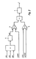
- the method according to the invention can assume three states, which are shown in FIG.
- a first state 1 the method is "inactive".
- a status variable tpmCSCSTAT has the value 0.
- the method transitions to a second state 2 when the lateral acceleration mrmAQRabs acting on the motor vehicle is greater than or equal to an associated acceleration threshold tpwCSCAY and if the engine torque mrmMOMOT is greater than or equal to a corresponding first threshold tpwCSCMOM1 is.
- the second state 2 indicates a cornering of the motor vehicle ("curve").
- the status variable tpmCSCSTAT has the value 1.
- the method returns to the first state 1 when the lateral acceleration mrmAQRabs is less than the associated acceleration threshold tpwCSCAY. Both in the first state 1 and in the second state 2 there is no change in the intervention variable in the sense of a specification of a minimum value.
- the method transitions to a third state 3 when the engine torque mrmMOMOT is smaller than or equal to the associated first threshold value tpwCSCMOM1.
- the method is "active", there is an intervention by a minimum value for the intervention size is output.
- the status variable tpmCSCSTAT has the value 2. The method exits the third state 3 and changes to the first state 1 when the engine torque mrmMOMOT is greater than or equal to a corresponding second threshold value tpwCSCMOM2.
- the procedure is from the DE 199 13 825 known, up which is expressly incorporated herein by reference.
- the predetermined minimum value of the intervention variable or the time duration, for which the drive motor is subjected to the minimum value according to the present invention as a function of corrected various driving dynamics parameters.
- FIG. 2 shows a functional diagram of a preferred embodiment of the method according to the invention.
- the determined minimum value of the intervention variable is not corrected, but the time duration t, for which the drive motor is subjected to the determined minimum value.
- a processing unit 4 In order to determine the friction coefficient MUE of the roadway, information about the activation of an anti-lock braking system ABS, traction control ASR and an engine drag torque control MSR are used. In a processing unit 4 it is determined how many times within a predeterminable time window and / or with which intensity one or more of these functions have been activated. An output MUE of the processing unit 4 is fed to a comparison unit 5, where it is compared with an associated threshold tpwMUE. If the output signal MUE is smaller than the threshold value tpwMUE, a low coefficient of friction MUE of the roadway is assumed.
- a second comparison unit 6 the delay VERZ of the motor vehicle with an associated threshold value tpwVERZ compared. If the coefficient of friction MUE of the roadway falls below the threshold value tpwMUE and / or the delay VERZ exceeds the threshold value tpwVERZ, the time duration t for which the drive motor is subjected to the minimum value of the intervention variable is extended in a delay unit 7. A corresponding functional diagram is shown in FIG.
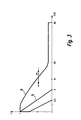
- curves of various correction values as a function of the time duration t for which the corrected minimum value of the intervention variable is applied to the drive motor are shown for different coefficients of friction MUE of a roadway.
- the duration of action t of the method according to the invention is - illustrated by a double arrow ⁇ - extended at a low coefficient of friction MUE (-) of the road (see curve 8).
- the duration of action t of the method according to the invention can be correspondingly shortened (compare curve 9).
- the duration or the frequency of the response of a low coefficient indicator MUE extends the duration of action t of the method according to the invention.
- the coefficient of friction MUE of the roadway can also be determined by evaluating the rotational speeds N of the wheels of the motor vehicle, in particular the drive wheels. Also conceivable would be an optical evaluation of the road or an acoustic evaluation of the tire noise. Finally, the friction coefficient MUE of the roadway could also be determined by means of suitable sensors incorporated in the tire walls, for example by means of strain gauges DMS.
- the determined minimum value of the intervention variable could also be raised for correction, if the friction coefficient MUE of the roadway falls below the threshold value tpwMUE and / or the delay VERZ exceeds the threshold value tpwVERZ.
- this can also be corrected as a function of further driving dynamics parameters, as shown in FIG. 4.
- a variable tpmN for the rotational speed of the drive motor and a further variable tpmAY for the lateral acceleration of the motor vehicle are fed to a map tpwCSCNAKF, on the basis of which a rotational speed and lateral acceleration-dependent minimum value tpmCSCNAKF for the intervention variable is determined.
- the minimum value tpmCSCNAKF can be corrected as a function of the absolute altitude at which the motor vehicle is located. For this purpose, an absolute value corresponding to the offset value tpmCSCSVKF is added to the minimum value tpmCSCNAKF.
- the offset value tpmCSCSVKF is final-dependent and therefore can not be applied.
- the minimum value tpmCSCNAKF can be corrected as a function of the gradient tpmSTEIG of the roadway on which the motor vehicle is traveling. For this purpose, the slope tmpSTEIG is fed to a map tpwCSCSTKL, based on which a slope-dependent correction factor tpmCSCSTKL is determined. The minimum value tpmCSCNAKF or the corrected minimum value is multiplied by the correction factor tpmCSCSTKL.
- Further correction values can be added to the minimum value tpmCSCNAKF if there is a lateral acceleration of the motor vehicle or if the speed and lateral acceleration-dependent minimum value tpmCSCNAKF is greater than 0.
- the minimum value tpmCSCNAKF is passed to a comparison unit 12, where it has the value "0". is compared.
- the output signal of the comparison unit 12 drives a switching unit 13. If the minimum value tpmCSCNAKF is less than or equal to "0", the switching unit 13 remains in the position shown in FIG. 4 and at its output is the value "0".
- the switching unit 13 switches on and the further correction values tpmCSCWTKL, tpmCSCGAKL and / or tpmCSCKIK are applied to the output of the switching unit 13.
- a variable tpmWTF for the temperature of the drive motor is fed to a further map tpwCSCWTKL, on the basis of which a temperature-dependent correction value tpmCSCWTKL is determined.
- Another map tpwCSCGAKL is supplied with a quantity tpmGANG for the engaged gear of a transmission unit of the motor vehicle.
- an aisle position-dependent correction value tpmCSCGAKL is determined, which is added to the temperature-dependent correction value tpmCSCWTKL.
- Another variable tpmFKLE contains information about whether an air conditioning compressor of the motor vehicle is in operation or not.
- the variable tpmFKLE is fed to a comparison unit 10.
- a switching unit 11 In response to an output signal of the comparison unit 10, a switching unit 11 is driven. If the air conditioning compressor is in operation, the switching unit 11 is actuated, so that at the output of the switching unit 11 is applied a consumer-dependent correction value tpmCSCKLIK. Otherwise, the switching unit 11 remains in the position shown in Fig. 4 and at the output of the switching unit 11 is "0".
- the method according to the invention becomes active if the gradient-compensated sum tpmCSCSUSK is greater than the determined value tpmESG for the setting value minus an offset tpwCSCARDO.
- the comparison takes place in a comparison unit 15. With the aid of an output signal of the comparison unit 15, a switching unit 16 is driven. As output signal, the switching unit 16 outputs either the time counter tpmCSCTIME or a value of the time counter tpmCSCTIME increased by a certain addend (+1 or +4).
- FIG. 6 shows a further functional diagram in which, in order to avoid jumps in the intervention variable, the corrected minimum value of the intervention variable is gradient-limited over a temporal ramp tpwCSCRAMP.
- a weighting factor tpmCSCTIKL is determined in a map tpwCSCTIKL as a function of the time counter tpmCSCTIME. This is usually between 0 and 3.
- the slope-compensated sum tpmCSCSUSK is multiplied by the weighting factor tpmCSCTIKL.
- the output quantity of the multiplication is a time-weighted sum tpmCSCSUTI. From the time-weighted sum tpmCSCSUTI, the gradient tpmCSCGRAD of the setting variable is calculated in a function block 19. Furthermore, a slope-limited output signal tpmCSCOUT is determined from the time-weighted sum tpmCSCSUTI by means of a characteristic diagram tpwCSCRAMP.
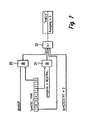
- FIG. 7 illustrates when the method according to the invention is deactivated. This is, for example, the case when a coupling dimKUP of the motor vehicle is open and no intervention by the method according to the invention is desired (AND operation 20).
- the method is also activated when the gear gangstat of the motor vehicle is in a neutral position NEUTRAL and no intervention by the inventive method is desired (AND operation 21).
- the method is deactivated when a main switch is turned off.
- the method according to the invention is also deactivated when the status variable tpmCSCSTAT # 2 is (see Fig. 1). If one of these conditions exists, the inventive method is deactivated and all outputs are reset.
Landscapes
- Engineering & Computer Science (AREA)
- Transportation (AREA)
- Mechanical Engineering (AREA)
- Chemical & Material Sciences (AREA)
- Combustion & Propulsion (AREA)
- Automation & Control Theory (AREA)
- Electric Propulsion And Braking For Vehicles (AREA)
- Control Of Vehicle Engines Or Engines For Specific Uses (AREA)
- Electrical Control Of Air Or Fuel Supplied To Internal-Combustion Engine (AREA)
- Electrical Control Of Ignition Timing (AREA)
- Control Of Throttle Valves Provided In The Intake System Or In The Exhaust System (AREA)
- Control Of Driving Devices And Active Controlling Of Vehicle (AREA)
Abstract
Description
Die vorliegende Erfindung betrifft ein Verfahren zur Beeinflussung eines von einem Antriebsmotor eines Kraftfahrzeugs abgegebenen Moments. Bei dem Verfahren wird
- ein während einer Kurvenfahrt des Kraftfahrzeugs auftretender Lastwechsel ermittelt;
- ein Minimalwert einer das abgegebene Moment beeinflussende Eingriffsgröße ermittelt, falls während einer Kurvenfahrt ein Lastwechsel auftritt; und
- der Antriebsmotor für eine vorgebbare Zeitdauer mit dem Minimalwert der Eingriffsgröße beaufschlagt.
- determines a load change occurring during cornering of the motor vehicle;
- determining a minimum value of an intervention variable influencing the output torque if a load change occurs during cornering; and
- the drive motor for a predetermined period of time applied to the minimum value of the intervention variable.
Die Erfindung betrifft außerdem ein Steuergerät für eine Fahrdynamikregelung eines Kraftfahrzeugs. Das Steuergerät
- ermittelt einen während einer Kurvenfahrt des Kraftfahrzeugs auftretenden Lastwechsel;
- ermittelt einen Minimalwert einer Eingriffsgröße, die ein von einem Antriebsmotor des Kraftfahrzeugs abgegebenes Moment beeinflusst, falls während einer Kurvenfahrt ein Lastwechsel auftritt; und
- beaufschlagt den Antriebsmotor für eine vorgebbare Zeitdauer mit dem Minimalwert der Eingriffsgröße.
- determines a load change occurring during cornering of the motor vehicle;
- determines a minimum value of an intervention variable which influences a torque output by a drive motor of the motor vehicle if a load change occurs during cornering; and
- acts on the drive motor for a predefinable period of time with the minimum value of the intervention variable.
Die vorliegende Erfindung betrifft des Weiteren ein Speicherelement für ein Steuergerät einer Fahrdynamikregelung eines Kraftfahrzeugs. Das Speicherelement ist insbesondere als ein Read-Only-Memory, als ein Random-Access-Memory oder als ein Flash-Memory ausgebildet. Auf dem Speicherelement ist ein Computerprogramm abgespeichert, das auf einem Rechengerät, insbesondere auf einem Mikroprozessor, ablauffähig ist. Schließlich betrifft die Erfindung auch ein solches Computerprogramm.The present invention further relates to a memory element for a control device of a vehicle dynamics control of a motor vehicle. The Memory element is designed in particular as a read-only memory, as a random access memory or as a flash memory. On the storage element, a computer program is stored, which is executable on a computing device, in particular on a microprocessor. Finally, the invention also relates to such a computer program.
Verfahren und Vorrichtungen zur Beeinflussung des Moments eines Antriebsmotors eines Kraftfahrzeugs sind aus dem Stand der Technik in vielerlei Modifikationen bekannt.Methods and devices for influencing the torque of a drive motor of a motor vehicle are known from the prior art in many modifications.
So ist aus der
Zur Bewertung des aktuellen Fahrzustands werden ferner die Geschwindigkeit des Kraftfahrzeugs und/oder die Drehzahl der Brennkraftmaschine und/oder die Stellung einer Gangschaltung und/oder ein Ausgangssignal einer Kurvenfahrterkennung und/oder eine auf das Kraftfahrzeug wirkende Querbeschleunigung und/oder der Reibwert der Fahrbahn und/oder ein Schlupf eines der Räder des Kraftfahrzeugs, insbesondere eines Antriebsrades, verarbeitet.For evaluating the current driving state, the speed of the motor vehicle and / or the rotational speed of the internal combustion engine and / or the position of a gearshift and / or an output signal of a cornering detection and / or acting on the motor vehicle lateral acceleration and / or the coefficient of friction of the roadway and / or or a slip of one of the wheels of the motor vehicle, in particular a drive wheel processed.
Hinsichtlich der Kurvenfahrt wird lediglich ermittelt, ob eine Kurvenfahrt vorliegt oder nicht. Eine Ermittlung, ob während der Kurvenfahrt gleichzeitig ein Lastwechsel vorliegt, wird nicht vorgenommen. D. h. die Beeinflussung der Kraftstoffzumessung im Schubbetrieb findet während einer Kurvenfahrt in jedem Fall statt, selbst dann, wenn während der Kurvenfahrt kein Lastwechsel vorliegt.With regard to cornering, it is only determined whether there is a cornering or not. A determination as to whether there is a load change during cornering is not carried out. Ie. the influence of the fuel metering in overrun takes place during cornering in each case, even if there is no load change during cornering.
Aus der
Ein Verfahren zur Kraftstoffzumessung im Schubbetrieb bzw. eine Schleppmomentbeeinflussung bzw. -regelung kann bspw. in einer Antriebsschlupfregelung, wie sie in dem SAE-Paper 870 337 "ASR-Traction Control - A Logical Extension of ABS" beschrieben ist, oder in einer Gierratenregelung, wie sie aus der in der
Ferner kann sie auch in einem Verfahren zur Einstellung des Vortriebs, wie es in der
Ferner ist der Einsatz einer Schleppmomentenbeeinflussung auch in einer Vorrichtung denkbar, wie sie in der
Aus der
Ausgehend von dem eingangs beschriebenen Stand der Technik liegt der vorliegenden Erfindung die Aufgabe zugrunde, eine Verbesserung des Lastwechselverhaltens eines Kraftfahrzeuges bei Kurvenfahrt und eine Verbesserung des Fahrverhaltens des Kraftfahrzeugs im Schubbetrieb zu erreichen.Based on the above-described prior art The object of the present invention is to achieve an improvement in the load-changing behavior of a motor vehicle when cornering and an improvement in the driving behavior of the motor vehicle during coasting.
Zur Lösung dieser Aufgabe schlägt die Erfindung ausgehend von dem Verfahren der eingangs genannten Art vor, dass der ermittelte Minimalwert der Eingriffsgröße und/oder die Zeitdauer, für die der Antriebsmotor mit dem Minimalwert beaufschlagt wird, in Abhängigkeit von dem Reibwert einer Fahrbahn, auf der das Kraftfahrzeug fährt, und/oder in Abhängigkeit von einer Verzögerung des Kraftfahrzeugs korrigiert wird.To solve this problem, the invention proposes starting from the method of the type mentioned that the determined minimum value of the intervention size and / or the period of time for which the drive motor is subjected to the minimum value, depending on the coefficient of friction of a road on which Motor vehicle moves, and / or is corrected in response to a deceleration of the motor vehicle.
Bei plötzlichem Gaswegnehmen in einer Kurve können die angetriebenen Räder eines Kraftfahrzeugs in Bremsschlupf geraten. Falls es sich bei den Antriebsrädern um die Hinterräder des Fahrzeugs handelt, kann in dieser Situation das Heck des Fahrzeugs ausbrechen. Um dies zu verhindern, wird in dieser Situation für die Eingriffsgröße ein Minimalwert vorgegeben, der aus Gründen der fahrdynamischen Stabiltät des Kraftfahrzeugs in dieser Situation nicht unterschritten werden sollte.With sudden gas take away in a curve, the driven wheels of a motor vehicle can fall into brake slippage. If the drive wheels are the rear wheels of the vehicle, the rear of the vehicle may break in this situation. In order to prevent this, a minimum value is predefined for the intervention variable in this situation, which should not be undershot for reasons of the dynamic driving stability of the motor vehicle in this situation.
Bei einer Fahrbahn mit einem niedrigen Reibwert oder bei einer hohen Verzögerung des Kraftfahrzeugs während einer Kurvenfahrt wird die Gefahr eines ausbrechenden Hecks des Fahrzeugs weiter erhöht. Ein vorgegebener Minimalwert, der bei griffiger Fahrbahn oder einer geringen Verzögerung eine ausreichende fahrdynamische Stabilität des Fahrzeugs sicherstellt, kann bei rutschiger Fahrbahn oder bei einer starken Verzögerung des Fahrzeugs zu einem Ausbrechen des Hecks führen. Um dies zu verhindern wird der vorgegebene Minimalwert der Eingriffsgröße bzw. die Zeitdauer, während der der Antriebsmotor mit dem Minimalwert beaufschlagt wird, bei dem erfindungsgemäßen Verfahren in Abhängigkeit des Reibwerts der Fahrbahn bzw. der Verzögerung des Fahrzeugs nach oben korrigiert. Der Minimalwert der Eingriffsgröße kann, bspw. bei einer Fahrbahn mit einem besonders hohen Reibwert oder einer besonders geringen Verzögerung des Kraftfahrzeugs, aber auch nach unten korrigiert werden.In a roadway with a low coefficient of friction or a high deceleration of the motor vehicle during cornering, the risk of an erupting rear of the vehicle is further increased. A predetermined minimum value, which ensures a sufficient driving dynamic stability of the vehicle in the case of a grip road or a slight deceleration, can lead to a breakout of the rear on a slippery road surface or in the event of a pronounced deceleration of the vehicle. To prevent this is the default Minimum value of the intervention variable or the period during which the drive motor is acted upon by the minimum value, corrected in the inventive method depending on the coefficient of friction of the road or the deceleration of the vehicle upwards. The minimum value of the engagement variable can be corrected, for example, in the case of a roadway with a particularly high coefficient of friction or a particularly low deceleration of the motor vehicle, but also downwards.
Erfindungsgemäß wird also der Reibwert der Fahrbahn bei der Ermittlung des Minimalwerts der Eingriffsgröße berücksichtigt. Das von dem Antriebsmotor des Kraftfahrzeugs abgegebene Moment wird in Abhängigkeit des Reibwerts der Fahrbahn beeinflusst. Da der Reibwert der Fahrbahn einen wichtigen Einfluss auf die Fahrstabilität des Kraftfahrzeugs bei Kurvenfahrt und insbesondere bei einem Lastwechsel während der Kurvenfahrt hat, kann mit dem erfindungsgemäßen Verfahren das Lastwechselverhalten des Kraftfahrzeugs deutlich verbessert und die fahrdynamische Stabilität des Fahrzeugs entscheidend erhöht werden.According to the invention, therefore, the coefficient of friction of the roadway is taken into account in the determination of the minimum value of the intervention variable. The torque delivered by the drive motor of the motor vehicle is influenced as a function of the coefficient of friction of the roadway. Since the coefficient of friction of the road has an important influence on the driving stability of the motor vehicle when cornering and especially during a load change during cornering, can be significantly improved with the inventive method, the load change behavior of the motor vehicle and the driving dynamics stability of the vehicle can be significantly increased.
Des Weiteren wird bei dem erfindungsgemäßen Verfahren eine Verzögerung des Kraftfahrzeugs bei der Ermittlung des Minimalwerts der Eingriffsgröße berücksichtigt. Das von dem Antriebsmotor des Kraftfahrzeugs abgegebene Moment wird in Abhängigkeit der Verzögerung beeinflusst. Auch das Verzögerungsverhalten des Kraftfahrzeugs hat einen entscheidenden Einfluss auf das Lastwechselverhalten während einer Kurvenfahrt und auf das Fahrdynamikverhalten des Kraftfahrzeugs. Die Verzögerung des Kraftfahrzeugs kann alternativ oder zusätzlich zu dem Reibwert der Fahrbahn berücksichtigt werden.Furthermore, in the method according to the invention, a deceleration of the motor vehicle is taken into account in the determination of the minimum value of the intervention variable. The torque delivered by the drive motor of the motor vehicle is influenced as a function of the deceleration. The deceleration behavior of the motor vehicle also has a decisive influence on the load change behavior during cornering and on the driving dynamics behavior of the motor vehicle. The deceleration of the motor vehicle can be taken into account as an alternative or in addition to the coefficient of friction of the roadway.
Die Verzögerung des Kraftfahrzeugs kann bspw. mittels eines Beschleunigungssensors oder durch Auswerten der Bremsaktivität ermittelt werden. Der Reibwert der Fahrbahn kann bspw. durch Auswerten der Drehzahlen der Räder, insbesondere durch einen Vergleich der Drehzahl der angetriebenen Räder mit der Drehzahl der nicht angetriebenen Räder, ermittelt werden. Es ist auch denkbar, den Reibwert der Fahrbahn mittels geeigneter Reifensensoren zu ermitteln, die als in die Reifenwand eingearbeitete Dehnmessstreifen (DMS) ausgebildet sein können. Ein Übergang von Haftreibung zu Gleitreibung kann durch einen Sprung in den Ausgangssignalen der Reifensensoren ermittelt werden. Zusammen mit der Querbeschleunigung, die auf das Kraftfahrzeug wirkt, und anderer Fahrzeugparameter kann dann der Reibwert der Fahrbahn ermittelt werden. Der Reibwert der Fahrbahn kann auch durch eine optische Abtastung der Fahrbahn oder durch Auswerten der Abrollgeräusche der Räder des Kraftfahrzeugs ermittelt werden.The deceleration of the motor vehicle can, for example, by means of an acceleration sensor or by evaluating the Braking activity are determined. The coefficient of friction of the road can be determined, for example, by evaluating the rotational speeds of the wheels, in particular by comparing the rotational speed of the driven wheels with the rotational speed of the non-driven wheels. It is also conceivable to determine the coefficient of friction of the roadway by means of suitable tire sensors which can be designed as strain gauges (DMS) incorporated in the tire wall. A transition from static friction to sliding friction can be determined by a jump in the output signals of the tire sensors. Together with the lateral acceleration, which acts on the motor vehicle, and other vehicle parameters, the coefficient of friction of the roadway can then be determined. The coefficient of friction of the road can also be determined by an optical scanning of the road or by evaluating the rolling noise of the wheels of the motor vehicle.
Ziel der vorliegenden Erfindung ist es, einem Ausbrechen des Kraftfahrzeugs während einer Kurvenfahrt aufgrund eines niedrigen Reibwerts der Fahrbahn oder einer starken Verzögerung des Kraftfahrzeugs durch Erhöhen des von dem Antriebsmotor des Kraftfahrzeugs abgegebenen Moments entgegenzuwirken. Dabei kommt es nicht nur auf eine Korrektur des Minimalwerts der Eingriffsgröße bzw. des abgegebenen Motormoments an.The aim of the present invention is to counteract a breaking of the motor vehicle during cornering due to a low coefficient of friction of the road or a strong deceleration of the motor vehicle by increasing the output from the drive motor of the motor vehicle torque. It is not only a matter of correcting the minimum value of the intervention variable or of the delivered engine torque.
In bestimmten Betriebspunkten der Brennkraftmaschine oder in bestimmten fahrdynamischen Zuständen des Kraftfahrzeugs kann es u.U. vorteilhaft sein, den Antriebsmotor für eine längere Zeitdauer mit dem vorgegebenen Minimalwert der Eingriffsgröße zu beaufschlagen. Dadurch wird der Gradient, mit dem die Korrektur der Eingriffsgröße auf Null geht, beeinflusst. Als Korrektur des ermittelten Minimalwerts der Eingriffsgröße kommt erfindungsgemäß also sowohl eine Korrektur des Minimalwertes als auch eine Korrektur der Zeitdauer in Betracht, während der der vorgegebene Minimalwert an dem Antriebsmotor anliegt.In certain operating points of the internal combustion engine or in certain driving dynamic states of the motor vehicle, it may be advantageous to apply the predetermined minimum value of the intervention variable to the drive motor for a longer period of time. This influences the gradient with which the correction of the intervention variable goes to zero. As a correction of the determined minimum value of the intervention size, both a correction of the minimum value and a correction of the invention thus come about Duration during which the predetermined minimum value is applied to the drive motor.
Gemäß einer vorteilhaften Weiterbildung der vorliegenden Erfindung wird vorgeschlagen, dass der ermittelte Minimalwert der Eingriffsgröße angehoben wird, falls der Reibwert der Fahrbahn einen vorgebbaren ersten Schwellenwert unterschreitet und/oder die Verzögerung des Kraftfahrzeugs einen vorgebbaren zweiten Schwellenwert überschreitet.According to an advantageous development of the present invention, it is proposed that the determined minimum value of the engagement variable be raised if the coefficient of friction of the roadway falls below a predefinable first threshold value and / or the deceleration of the motor vehicle exceeds a predefinable second threshold value.
Alternativ oder zusätzlich wird vorgeschlagen, dass der Antriebsmotor für eine längere Zeitdauer mit dem Minimalwert der Eingriffsgröße beaufschlagt wird, falls der Reibwert der Fahrbahn einen vorgebbaren ersten Schwellenwert unterschreitet und/oder die Verzögerung des Kraftfahrzeugs einen vorgebbaren zweiten Schwellenwert überschreitet. Gemäß dieser Weiterbildung erfolgt die Korrektur des vorgegebenen Minimalwerts der Eingriffsgröße dadurch, dass der Gradient, mit dem der Korrekturwert der Eingriffsgröße und somit der Korrekturanteil des von dem Antriebsmotor aufgebrachten Moments auf Null geht, beeinflusst wird.Alternatively or additionally, it is proposed that the drive motor be acted upon for a longer period of time with the minimum value of the intervention variable, if the coefficient of friction of the roadway falls below a predefinable first threshold value and / or the deceleration of the motor vehicle exceeds a predefinable second threshold value. According to this development, the correction of the predetermined minimum value of the intervention variable is effected in that the gradient with which the correction value of the intervention variable and thus the correction component of the torque applied by the drive motor approaches zero is influenced.
Gemäß einer bevorzugten Ausführungsform der vorliegenden Erfindung wird vorgeschlagen, dass der Minimalwert der Eingriffsgröße aus zwei Werten ermitelt wird, wobei
- ein erster Wert in Abhängigkeit von der Drehzahl des Antriebsmotors und von einer Querbeschleunigung des Kraftfahrzeugs ermittelt wird;
- ein zweiter Wert in Abhängigkeit von einem Schlupf mindestens eines der Räder des Kraftfahrzeugs und von einer Geschwindigkeit des Kraftfahrzeugs ermittelt wird; und
- der Minimalwert aus der Summe des ersten Werts und des zweiten Werts ermittelt wird.
- a first value is determined as a function of the rotational speed of the drive motor and of a transverse acceleration of the motor vehicle;
- a second value is determined in dependence on a slip of at least one of the wheels of the motor vehicle and on a speed of the motor vehicle; and
- the minimum value is determined from the sum of the first value and the second value.
Dabei gelten die folgenden Zusammenhänge: Je größer die Motordrehzahl ist, desto größer ist der erste Wert der Eingriffsgröße. Durch diese Maßnahme wird die bei steigender Motordrehzahl größer werdende Reibung im Motor kompensiert. Je größer die Querbeschleunigung ist, desto größer ist der erste Wert der Eingriffsgröße. Die Eingriffsgröße wird bei einer entsprechend großen Querbeschleunigung auf den Minimalwert angehoben, damit ein Schleppmoment nicht zu groß ist und somit die Seitenführung des Kraftfahrzeugs gewährleistet ist. Je größer ein Radschlupf ist, desto größer ist der zweite Wert der Eingriffsgröße. Da ein großer Radschlupf auf eine glatte Fahrbahn hindeutet, muss in dieser Situation die Eingriffsgröße erhöht werden. Je höher die Geschwindigkeit des Kraftfahrzeugs ist, desto größer ist der zweite Wert. Mit zunehmender Fahrzeuggeschwindigkeit steigt auch die Gefahr des Ausbrechens des Kraftfahrzeugs in einer Kurve. Durch ein Anheben des ermittelten Minimalwerts der Eingriffsgröße in dieser Situation kann das verhindert werden. Der erste Wert und der zweite Wert werden zu dem vorgegebenen Minimalwert der Eingriffsgröße addiert. Das Verfahren gemäß dieser Ausführungsform ist an sich aus der
Vorteilhafterweise wird der Minimalwert der Eingriffsgröße in Abhängigkeit von zwei Kennfeldern ermittelt, wobei der erste Wert anhand eines ersten Kennfelds und der zweite Wert anhand eines zweiten Kennfelds ermittelt wird. In dem ersten Kennfeld ist der erste Wert in Abhängigkeit von der Motordrehzahl und der Querbeschleunigung abgelegt. In dem zweiten Kennfeld ist der zweite Wert in Abhängigkeit von dem Radschlupf und der Fahrzeuggeschwindigkeit abgelegt.Advantageously, the minimum value of the intervention variable is determined as a function of two characteristic diagrams, wherein the first value is determined on the basis of a first characteristic field and the second value on the basis of a second characteristic field. In the first map, the first value is stored as a function of the engine speed and the lateral acceleration. In the second map, the second value is stored as a function of the wheel slip and the vehicle speed.
Eine weitere Korrekturmöglichkeit des ermittelten Minimalwerts der Eingriffsgröße besteht gemäß einer vorteilhaften Weiterbildung der vorliegenden Erfindung darin, dass der reibwert- bzw. verzögerungsabhängig korrigierte Minimalwert der Eingriffsgröße in Abhängigkeit von einer Steigung einer Fahrbahn, auf der das Kraftfahrzeug fährt, und/oder in Abhängigkeit einer absoluten Höhe, in der sich das Kraftfahrzeug befindet, korrigiert wird und der Antriebsmotor mit dem steigungs- bzw. höhenabhängig korrigierten Minimalwert beaufschlagt wird. Vorteilhafterweise wird der reibwert- bzw. verzögerungsabhängig korrigierte Minimalwert der Eingriffsgröße zur Korrektur mit einem steigungs- und/oder höhenabhängigen Korrekturfaktor multipliziert. Der Korrekturfaktor wird vorzugsweise anhand eines dritten Kennfeldes ermittelt. Dabei gilt folgender qualitativer Zusammenhang: Bei einer Bergabfahrt wird der Minimalwert der Eingriffsgröße nach unten korrigiert, also verkleinert, bei einer Bergauffahrt wird der Minimalwert nach oben korrigiert, also vergrößert.A further possibility of correction of the determined minimum value of the intervention variable according to an advantageous development of the present invention is that the friction value or delay-dependent corrected minimum value of the intervention variable as a function of a slope of a roadway on which the motor vehicle travels, and / or in dependence on an absolute Height at which the motor vehicle is located, is corrected and the drive motor with the slope or height-dependent corrected minimum value is applied. Advantageously, the friction value or delay-dependent corrected minimum value of the intervention variable for correction is multiplied by a slope-dependent and / or height-dependent correction factor. The correction factor is preferably determined on the basis of a third characteristic field. The following qualitative context applies: When going downhill, the minimum value of the intervention variable is corrected downwards, that is to say reduced, in the case of an uphill run the minimum value is corrected upwards, ie increased.
Gemäß einer anderen vorteilhaften Weiterbildung der vorliegenden Erfindung wird vorgeschlagen, dass der reibwert- bzw. verzögerungsabhängig korrigierte Minimalwert der Eingriffsgröße in Abhängigkeit von der Temperatur des Antriebsmotors korrigiert wird, falls eine Querbeschleunigung des Kraftfahrzeugs vorliegt, und der Antriebsmotor mit dem korrigierten Minimalwert beaufschlagt wird. Es gilt folgender Zusammenhang: Je niedriger die Temperatur des Antriebsmotors ist, desto größer ist ein Korrekturwert, um den der Minimalwert der Eingriffsgröße korrigiert wird. Dadurch sollen die Auswirkungen einer bei kaltem Antriebsmotor größeren Reibung kompensiert werden.According to another advantageous development of the present invention, it is proposed that the friction value or delay-dependent corrected minimum value of the intervention variable is corrected as a function of the temperature of the drive motor, if a transverse acceleration of the motor vehicle is present, and the drive motor is subjected to the corrected minimum value. The following relationship applies: the lower the temperature of the drive motor, the greater is a correction value by which the minimum value of the intervention variable is corrected. This is intended to compensate for the effects of greater friction when the drive motor is cold.
Gemäß noch einer anderen vorteilhaften Weiterbildung der vorliegenden Erfindung wird vorgeschlagen, dass der reibwert- bzw. verzögerungsabhängig korrigierte Minimalwert der Eingriffsgröße in Abhängigkeit von der Stellung eines Schaltgetriebes des Kraftfahrzeugs korrigiert wird, falls eine Querbeschleunigung des Kraftfahrzeugs vorliegt, und der Antriebsmotor mit dem korrigierten Minimalwert beaufschlagt wird. Das Schaltgetriebe kann elektronisch oder mechanisch schaltbar sein. In Abhängigkeit des eingelegten Ganges wird ein Korrekturwert bestimmt, um den der Minimalwert der Eingriffsgröße korrigiert wird. Dabei gilt folgender Zusammenhang: Je niedriger der eingelegte Gang ist, je größer ist der Korrekturwert, da die in dem Antriebsmotor auftretende Reibung bei kleinen Gängen größer ist als bei großen Gängen.According to yet another advantageous development of the present invention, it is proposed that the correction value or delay-dependent corrected minimum value of the intervention variable is corrected in dependence on the position of a gearbox of the motor vehicle, if a lateral acceleration of the motor vehicle is present, and the drive motor is acted upon with the corrected minimum value. The manual transmission can be electronically or mechanically switchable. Depending on the engaged gear, a correction value is determined by which the minimum value of the intervention variable is corrected. The following relationship applies here: the lower the engaged gear, the greater the correction value, since the friction occurring in the drive motor is greater for small gears than for large gears.
Gemäß noch einer anderen vorteilhaften Weiterbildung der vorliegenden Erfindung wird vorgeschlagen, dass der reibwert- bzw. verzögerungsabhängig korrigierte Minimalwert der Eingriffsgröße in Abhängigkeit von der Art und Anzahl in dem Kraftfahrzeug enthaltener und in Betrieb befindlicher Verbraucher korrigiert wird, falls eine Querbeschleunigung des Kraftfahrzeugs vorliegt, und der Antriebsmotor mit dem korrigierten Minimalwert beaufschlagt wird. Gemäß dieser Weiterbildung wird in Abhängigkeit der eingeschalteten Verbraucher des Kraftfahrzeugs ein weiterer Korrekturwert bestimmt, um den der Minimalwert der Eingriffsgröße korrigiert wird. Es gilt folgender Zusammenhang: Je mehr Verbraucher im Betrieb sind, desto größer ist der Korrekturwert. Je größer die von den eingeschalteten Verbrauchern benötigte Leistung ist, desto größer ist der Korrekturwert. Bei dieser Weiterbildung wird der Tatsache Rechnung getragen, dass nicht das gesamte von dem Antriebsmotor aufgebrachte Moment an die Antriebsräder übertragen wird, sondern ein Teil des aufgebrachten Moments durch in Betrieb befindliche Verbraucher des Kraftfahrzeugs verbraucht. Je mehr Verbraucher sich im Betrieb befinden und je mehr Leistung die Verbraucher benötigen, desto höher ist der Anteil des Motormoments, das nicht auf die Antriebsräder übertragen wird. Bei den Verbrauchern, die in diesem Zusammenhang berücksichtigt werden, handelt es sich um Verbraucher mit einer relativ großen Leistungsaufnahme, bspw. einer Klimaanlage, eine Scheibenheizung oder eine verbesserte Lichtanlage auf der Basis von Xenon-Licht.In accordance with yet another advantageous development of the present invention, it is proposed that the minimum value of the intervention variable corrected for friction or delay be corrected as a function of the type and number of consumers contained in the motor vehicle and in operation if there is a lateral acceleration of the motor vehicle, and the drive motor is supplied with the corrected minimum value. According to this development, a further correction value is determined as a function of the switched-on consumers of the motor vehicle, by which the minimum value of the intervention variable is corrected. The following relationship applies: The more consumers are in operation, the greater the correction value. The greater the power required by the switched-on consumers, the greater the correction value. In this development, the fact is taken into account that not all of the torque applied by the drive motor is transmitted to the drive wheels, but consumes a portion of the applied torque consumed by in-service consumers of the motor vehicle. The more consumers are in operation and the more power consumers need, the higher is the proportion of engine torque that is not transmitted to the drive wheels. The consumers considered in this context are consumers with a relatively high power consumption, for example an air conditioning system, a window heating or an improved lighting system based on xenon light.
Anders als die steigungs- oder höhenabhängige Korrektur erfolgt die temperaturabhängige, die getriebestellungsabhängige und die verbraucherabhängige Korrektur des Minimalwerts der Eingriffsgröße nur, falls eine Querbeschleunigung des Kraftfahrzeugs vorliegt. Anders als bei der steigungs- oder höhenabhängigen Korrektur wird zur Korrektur von Einflüssen der Motortemperatur der Getriebestellung und von Verbrauchern ein motortemperatur-, getriebestellungs- und/oder verbraucherabhängiger Korrekturwert zu dem Minimalwert der Eingriffsgröße addiert.Unlike the slope or height-dependent correction, the temperature-dependent, the gear position-dependent and the consumer-dependent correction of the minimum value of the intervention variable is carried out only if there is a transverse acceleration of the motor vehicle. Unlike the slope or height-dependent correction, a motor temperature, getriebestellungs- and / or consumer-dependent correction value is added to the minimum value of the mesh size to correct for influences of the engine temperature of the gear position and consumers.
Gemäß noch einer weiteren bevorzugten Ausführungsform der vorliegenden Erfindung wird vorgeschlagen, dass zur Ermittlung eines Lastwechsels die Stellung eines Fahrpedals des Kraftfahrzeugs oder das von dem Antriebsmotor abgegebene Moment ausgewertet wird. Als Lastwechsel wird ein Übergang von einem Zugbetrieb in einen Schubbetrieb bezeichnet.According to yet another preferred embodiment of the present invention, it is proposed that the position of an accelerator pedal of the motor vehicle or the torque output by the drive motor is evaluated to determine a load change. Load change is a transition from a pull to a push.
Die Art der das abgegebene Moment beeinflussenden Eingriffsgröße hängt von verschiedenen Faktoren ab. Zum einen können für unterschiedliche Antriebsmotoren auch unterschiedliche Eingriffsgrößen eingesetzt werden, durch die das von dem Antriebsmotor abgegebene Moment beeinflusst wird. Bei ein und demselben Antriebsmotor kann es außerdem verschiedene Eingriffsgrößen geben, durch die das von dem Antriebsmotor abgegebene Moment beeinflusst werden kann.The type of intervention variable influencing the delivered moment depends on various factors. On the one hand, different engagement variables can be used for different drive motors, by which the torque delivered by the drive motor is influenced. In the case of one and the same drive motor, there may also be various engagement variables by which the torque output by the drive motor can be influenced.
Gemäß einer bevorzugten Ausführungsform der vorliegenden Erfindung wird vorgeschlagen, dass als die das abgegebene Moment beeinflussende Eingriffsgröße eine in einen Brennraum eines als direkteinspritzende Brennkraftmaschine ausgebildeten Antriebsmotors einzuspritzende Kraftstoffmenge herangezogen wird. Bei einer Saugrohreinspritzung kann auch die in das Saugrohr einzuspritzende Kraftstoffmenge herangezogen werden.According to a preferred embodiment of the present invention, it is proposed that the quantity of fuel to be injected into a combustion chamber of a drive motor designed as a direct-injection internal combustion engine be used as the intervention variable influencing the output torque. In the case of intake manifold injection, the amount of fuel to be injected into the intake manifold can also be used.
Gemäß einer weiteren bevorzugten Ausführungsform der vorliegenden Erfindung wird vorgeschlagen, dass als die das abgegeben Moment beeinflussende Eingriffsgröße bei einem als Brennkraftmaschine ausgebildeten Antriebsmotor ein Zeitpunkt zum Einspritzen von Kraftstoff herangezogen wird.According to a further preferred embodiment of the present invention, it is proposed that a moment for injecting fuel be used as the engagement variable influencing the output torque in a drive motor embodied as an internal combustion engine.
Gemäß noch einer weiteren bevorzugten Ausführungsform der vorliegenden Erfindung wird vorgeschlagen, dass als die das abgebende Moment beeinflussende Eingriffsgröße ein Zeitpunkt zum Zünden eines in einem Brennraum eines als Brennkraftmaschine ausgebildeten Antriebsmotors befindlichen Kraftstoff-/Luftgemisches herangezogen wird.According to yet another preferred embodiment of the present invention, it is proposed that a time for igniting a fuel / air mixture located in a combustion chamber of a drive motor designed as an internal combustion engine is used as the engagement variable influencing the emitting moment.
Des Weiteren wird vorgeschlagen, dass als die das abgegebene Moment beeinflussende Eingriffsgröße ein Winkel einer Drosselklappe eines als Brennkraftmaschine ausgebildeten Antriebsmotors herangezogen wird.Furthermore, it is proposed that an angle of a throttle flap of a drive motor designed as an internal combustion engine be used as the intervention variable influencing the output torque.
Schließlich wird vorgeschlagen, dass als die das abgegebene Moment beeinflussende Eingriffsgröße ein Strom oder eine Spannung eines als Elektromotor ausgebildeten Antriebsmotors herangezogen wird.Finally, it is proposed that a current or a voltage of a drive motor designed as an electric motor be used as the intervention variable influencing the output torque.
Als eine weitere Lösung der Aufgabe der vorliegenden Erfindung wird ausgehend von dem Steuergerät der eingangs genannten Art vorgeschlagen, dass das Steuergerät den ermittelten Minimalwert der Eingriffsgröße und/oder die Zeitdauer, für die der Antriebsmotor mit dem Minimalwert beaufschlagt wird, in Abhängigkeit von dem Reibwert einer Fahrbahn, auf der das Kraftfahrzeug fährt, und/oder in Abhängigkeit von einer Verzögerung des Kraftfahrzeugs korrigiert.As a further solution of the object of the present invention is proposed starting from the control unit of the type mentioned that the control unit, the determined minimum value of the intervention size and / or Duration, for which the drive motor is subjected to the minimum value, depending on the coefficient of friction of a road on which the motor vehicle is traveling, and / or corrected in response to a deceleration of the motor vehicle.
Gemäß einer vorteilhaften Weiterbildung der vorliegenden Erfindung wird vorgeschlagen, dass in dem Steuergerät Mittel zur Ausführung des erfindungsgemäßen Verfahrens realisiert sind.According to an advantageous development of the present invention, it is proposed that means for carrying out the method according to the invention are realized in the control unit.
Von besonderer Bedeutung ist die Realisierung des erfindungsgemäßen Verfahrens in der Form eines Speicherelements, das für ein Steuergerät einer Fahrdynamikregelung eines Kraftfahrzeugs vorgesehen ist. Dabei ist auf dem Speicherelement ein Computerprogramm abgespeichert, das auf einem Rechengerät, insbesondere auf einem Mikroprozessor, ablauffähig und zur Ausführung des erfindungsgemäßen Verfahrens geeignet ist. In diesem Fall wird also die Erfindung durch ein auf dem Speicherelement gespeichertes Computerprogramm realisiert, so dass dieses mit dem Computerprogramm versehene Speicherelement in gleicher Weise die Erfindung darstellt wie das Verfahren, zu dessen Ausführung das Computerprogramm geeignet ist. Als Speicherelement kann insbesondere ein elektrisches Speichermedium zur Anwendung kommen, bspw. ein Read-Only-Memory, ein Random-Access-Memory oder ein Flash-Memory.Of particular importance is the realization of the method according to the invention in the form of a memory element which is provided for a control unit of a driving dynamics control of a motor vehicle. In this case, a computer program is stored on the memory element, which is executable on a computing device, in particular on a microprocessor, and suitable for carrying out the method according to the invention. In this case, the invention is thus realized by a computer program stored on the memory element, so that this memory element provided with the computer program represents in the same way the invention as the method which the computer program is suitable for executing. In particular, an electrical storage medium can be used as the storage element, for example a read-only memory, a random access memory or a flash memory.
Die Erfindung betrifft schließlich auch ein Computerprogramm, das zur Ausführung des erfindungsgemäßen Verfahrens geeignet ist, wenn es auf einem Rechengerät, insbesondere auf einem Mikroprozessor, abläuft. Besonders bevorzugt ist dabei, wenn das Computerprogramm auf einem Speicherelement, insbesondere auf einem Flash-Memory, abgespeichert ist.Finally, the invention also relates to a computer program which is suitable for carrying out the method according to the invention when it runs on a computing device, in particular on a microprocessor. It is particularly preferred if the computer program is stored on a memory element, in particular on a flash memory.
Weitere Merkmale, Anwendungsmöglichkeiten und Vorteile der Erfindung ergeben sich aus der nachfolgenden Beschreibung von Ausführungsbeispielen der Erfindung, die in der Zeichnung dargestellt sind. Dabei bilden alle beschriebenen oder dargestellten Merkmale für sich oder in beliebiger Kombination den Gegenstand der Erfindung, unabhängig von ihrer Zusammenfassung in den Patentansprüchen oder deren Rückbeziehung sowie unabhängig von ihrer Formulierung bzw. Darstellung in der Beschreibung bzw. in der Zeichnung. Es zeigen:
Figur 1- ein Zustandsdiagramm eines erfindungsgemäßen Verfahrens zur Korrektur eines Minimalwerts einer Eingriffsgröße;
Figur 2- ein Funktionsdiagramm eines erfindungsgemäßen Verfahrens zur Korrektur eines Minimalwerts einer Eingriffsgröße;
Figur 3- Verläufe verschiedener Korrekturwerte in Abhängigkeit von der Zeitdauer, für die ein korrigierter Minimalwert einer Eingriffsgröße an einem Antriebsmotor eines Kraftfahrzeugs anliegt, für verschiedene Reibwerte einer Fahrbahn, auf der das Kraftfahrzeug fährt;
Figur 4- ein Funktionsdiagramm weiterer Ausgestaltungen eines erfindungsgemäßen Verfahrens;
Figur 5- ein Funktionsdiagramm eines Verfahrens zum Hochzählen eines Zeitzählers, der der Zeitdauer entspricht, für die der korrigierte Minimalwert der Eingriffsgröße an dem Antriebsmotor anliegt;
Figur 6- ein Funktionsdiagramm eines Verfahrens zur rampenförmigen Begrenzung des korrigierten Minimalwerts einer Eingriffsgröße; und
Figur 7- ein Funktionsdiagramm eines Verfahrens zur Deaktivierung des erfindungsgemäßen Verfahrens.
- FIG. 1
- a state diagram of a method according to the invention for correcting a minimum value of an intervention variable;
- FIG. 2
- a functional diagram of a method according to the invention for correcting a minimum value of an intervention variable;
- FIG. 3
- Curves of various correction values as a function of the time duration for which a corrected minimum value of an intervention variable is applied to a drive motor of a motor vehicle, for different coefficients of friction of a roadway on which the motor vehicle travels;
- FIG. 4
- a functional diagram of further embodiments of a method according to the invention;
- FIG. 5
- FIG. 5 is a functional diagram of a method of incrementing a time counter corresponding to the time duration for which the corrected minimum value of the engagement amount is applied to the drive motor; FIG.
- FIG. 6
- a functional diagram of a method for ramping the corrected Minimum value of an intervention variable; and
- FIG. 7
- a functional diagram of a method for deactivating the method according to the invention.
In Fig. 1 sind verschiedene Zustände eines erfindungsgemäßen Verfahrens zur Beeinflussung eines von einem Antriebsmotor eines Kraftfahrzeugs abgegebenen Moments dargestellt. Das von dem Antriebsmotor abgegebene Moment kann über eine Eingriffsgröße beeinflusst werden.In Fig. 1, various states of a method according to the invention for influencing a given by a drive motor of a motor vehicle torque are shown. The torque delivered by the drive motor can be influenced by an intervention variable.
Der Minimalwert der Eingriffsgröße und damit ein Minimalwert eines von dem Antriebsmotor abgegebenen Motormoments wird auf an sich aus dem Stand der Technik bekannte Weise von einem Steuergerät des Antriebsmotors ermittelt. So ist es aus der
Erfindungsgemäß wird der ermittelte Minimalwert der Eingriffsgröße in Abhängigkeit von dem Reibwert einer Fahrbahn, auf der das Kraftfahrzeug fährt, und/oder in Abhängigkeit von einer Verzögerung des Kraftfahrzeugs korrigiert. Alternativ oder zusätzlich kann auch die Zeitdauer, für die der Antriebsmotor mit dem Minimalwert der Eingriffsgröße beaufschlagt wird, reibwert- bzw. verzögerungsabhängig korrigiert werden. Dadurch kann das Kraftfahrzeug bei einem Lastwechsel während einer Kurvenfahrt auch in fahrdynamischen Extremsituationen (rutschige Fahrbahn, hohe Verzögerung) in einem fahrdynamisch stabilen Zustand gehalten oder fahrdynamisch stabilisiert werden.According to the invention, the determined minimum value of the intervention variable is corrected as a function of the coefficient of friction of a roadway on which the motor vehicle travels and / or as a function of a deceleration of the motor vehicle. Alternatively or additionally, the period of time for which the drive motor is subjected to the minimum value of the intervention variable can also be corrected by friction or delay. This allows the motor vehicle in a load change while cornering in extreme driving dynamic situations (slippery road, high deceleration) in one be kept dynamic driving stable state or driving dynamics stabilized.
Das erfindungsgemäße Verfahren kann drei Zustände einnehmen, die in Fig. 1 dargestellt sind. In einem ersten Zustand 1 ist das Verfahren "inaktiv". Eine Statusvariable tpmCSCSTAT hat den Wert 0. Von dem ersten Zustand 1 geht das Verfahren in einen zweiten Zustand 2 über, wenn die auf das Kraftfahrzeug wirkende Querbeschleunigung mrmAQRabs größergleich einem zugehörigen Beschleunigungs-Schwellenwert tpwCSCAY ist und wenn das Motormoment mrmMOMOT größergleich einem zugehörigen ersten Schwellenwert tpwCSCMOM1 ist. Der zweite Zustand 2 kennzeichnet eine Kurvenfahrt des Kraftfahrzeugs ("Kurve"). In dem zweiten Zustand 2 hat die Statusvariable tpmCSCSTAT den Wert 1. Von dem zweiten Zustand 2 geht das Verfahren wieder in den ersten Zustand 1 über, wenn die Querbeschleunigung mrmAQRabs kleiner als der zugehörige Beschleunigungs-Schwellenwert tpwCSCAY ist. Sowohl in dem ersten Zustand 1 als auch in dem zweiten Zustand 2 erfolgt keine Veränderung der Eingriffsgröße im Sinne einer Vorgabe eines Minimalwertes.The method according to the invention can assume three states, which are shown in FIG. In a
Von dem zweiten Zustand 2 geht das Verfahren in einen dritten Zustand 3 über, wenn das Motormoment mrmMOMOT kleinergleich dem zugehörigen ersten Schwellenwert tpwCSCMOM1 ist. In dem dritten Zustand 3 ist das Verfahren "aktiv", es erfolgt ein Eingriff, indem ein Minimalwert für die Eingriffsgröße ausgegeben wird. In dem dritten Zustand 3 hat die Statusvariable tpmCSCSTAT den Wert 2. Das Verfahren verlässt den dritten Zustand 3 und geht in den ersten Zustand 1 über, wenn das Motormoment mrmMOMOT größergleich einem zugehörigen zweiten Schwellenwert tpwCSCMOM2 ist.From the
Soweit ist das Verfahren aus der
Als fahrdynamische Parameter, in deren Abhängigkeit der Minimalwert der Eingriffsgröße korrigiert wird, wird der Reibwert einer Fahrbahn, auf der das Kraftfahrzeug fährt und/oder eine Verzögerung des Kraftfahrzeugs herangezogen. In Fig. 2 ist ein Funktionsdiagramm einer bevorzugten Ausführungsform des erfindungsgemäßen Verfahrens dargestellt. Dabei wird nicht der ermittelte Minimalwert der Eingriffsgröße korrigiert, sondern die Zeitdauer t, für die der Antriebsmotor mit dem ermittelten Minimalwert beaufschlagt wird.As a driving dynamics parameter, in dependence of which the minimum value of the intervention variable is corrected, the coefficient of friction of a roadway on which the motor vehicle travels and / or a deceleration of the motor vehicle is used. FIG. 2 shows a functional diagram of a preferred embodiment of the method according to the invention. In this case, the determined minimum value of the intervention variable is not corrected, but the time duration t, for which the drive motor is subjected to the determined minimum value.
Um den Reibwert MUE der Fahrbahn zu ermitteln, werden Informationen über die Aktivierung eines Antiblockiersystems ABS, einer Antischlupfregelung ASR und einer Motorschleppmomentregelung MSR herangezogen. In einer Verarbeitungseinheit 4 wird ermittelt, wie oft innerhalb eines vorgebbaren Zeitfensters und/oder mit welcher Intensität eine oder mehrere dieser Funktionen aktiviert wurden. Ein Ausgangssignal MUE der Verarbeitungseinheit 4 wird an eine Vergleichseinheit 5 geführt, wo es mit einem zugehörigen Schwellenwert tpwMUE verglichen wird. Falls das Ausgangssignal MUE kleiner als der Schwellenwert tpwMUE ist, wird von einem niedrigen Reibwert MUE der Fahrbahn ausgegangen.In order to determine the friction coefficient MUE of the roadway, information about the activation of an anti-lock braking system ABS, traction control ASR and an engine drag torque control MSR are used. In a
In einer zweiten Vergleichseinheit 6 wird die Verzögerung VERZ des Kraftfahrzeugs mit einem zugehörigen Schwellenwert tpwVERZ verglichen. Falls der Reibwert MUE der Fahrbahn den Schwellenwert tpwMUE unterschreitet und/oder die Verzögerung VERZ den Schwellenwert tpwVERZ überschreitet, wird in einer Verzögerungseinheit 7 die Zeitdauer t, für die der Antriebsmotor mit dem Minimalwert der Eingriffsgröße beaufschlagt wird, verlängert. Ein entsprechendes Funktionsdiagramm ist in Fig. 5 dargestellt.In a
In Fig. 3 sind Verläufe verschiedener Korrekturwerte in Abhängigkeit von der Zeitdauer t, für die der korrigierte Minimalwert der Eingriffsgröße an dem Antriebsmotor anliegt, für verschiedene Reibwerte MUE einer Fahrbahn dargestellt. Die Wirkungsdauer t des erfindungsgemäßen Verfahrens wird - durch einen Doppelpfeil µ verdeutlicht - bei einem niedrigen Reibwert MUE (-) der Fahrbahn verlängert (vgl. Kurve 8). Bei einem höheren Reibwert MUE (+) kann die Wirkungsdauer t des erfindungsgemäßen Verfahrens entsprechend verkürzt werden (vgl. Kurve 9). Somit verlängert die Dauer bzw. die Häufigkeit des Ansprechens eines Indikators für niedrige Reibwerte MUE die Wirkungsdauer t des erfindungsgemäßen Verfahrens.In FIG. 3, curves of various correction values as a function of the time duration t for which the corrected minimum value of the intervention variable is applied to the drive motor are shown for different coefficients of friction MUE of a roadway. The duration of action t of the method according to the invention is - illustrated by a double arrow μ - extended at a low coefficient of friction MUE (-) of the road (see curve 8). With a higher coefficient of friction MUE (+), the duration of action t of the method according to the invention can be correspondingly shortened (compare curve 9). Thus, the duration or the frequency of the response of a low coefficient indicator MUE extends the duration of action t of the method according to the invention.
Anders als in Fig. 2 dargestellt, kann der Reibwert MUE der Fahrbahn auch durch Auswerten der Drehzahlen N der Räder des Kraftfahrzeugs, insbesondere der Antriebsräder, ermittelt werden. Denkbar wäre auch eine optische Auswertung der Fahrbahn oder eine akustische Auswertung der Reifengeräusche. Schließlich könnte der Reibwert MUE der Fahrbahn auch mittels geeigneter in die Reifenwände eingearbeiteter Sensoren, bspw. mittels Dehnmessstreifen DMS, ermittelt werden.Unlike in FIG. 2, the coefficient of friction MUE of the roadway can also be determined by evaluating the rotational speeds N of the wheels of the motor vehicle, in particular the drive wheels. Also conceivable would be an optical evaluation of the road or an acoustic evaluation of the tire noise. Finally, the friction coefficient MUE of the roadway could also be determined by means of suitable sensors incorporated in the tire walls, for example by means of strain gauges DMS.
Alternativ zu der in Fig. 2 dargestellten Verlängerung der Wirkungsdauer t des erfindungsgemäßen Verfahrens mittels der Verzögerungseinheit 7 könnte zur Korrektur auch der ermittelte Minimalwert der Eingriffsgröße angehoben werden, falls der Reibwert MUE der Fahrbahn den Schwellenwert tpwMUE unterschreitet und/oder die Verzögerung VERZ den Schwellenwert tpwVERZ überschreitet.As an alternative to the extension of the duration of action t of the method according to the invention shown in FIG. 2 by means of the
Zusätzlich zu der in Fig. 2 dargestellten Möglichkeit der Korrektur des ermittelten Minimalwerts der Eingriffsgröße kann dieser - wie in Fig. 4 dargestellt - auch in Abhängigkeit von weiteren Fahrdynamikparametern korrigiert werden. Eine Größe tpmN für die Drehzahl des Antriebsmotors und eine weitere Größe tpmAY für die Querbeschleunigung des Kraftfahrzeugs werden einem Kennfeld tpwCSCNAKF zugeführt, anhand dessen ein drehzahl- und querbeschleunigungsabhängiger Minimalwert tpmCSCNAKF für die Eingriffsgröße ermittelt wird.In addition to the possibility of the correction of the determined minimum value of the intervention variable shown in FIG. 2, this can also be corrected as a function of further driving dynamics parameters, as shown in FIG. 4. A variable tpmN for the rotational speed of the drive motor and a further variable tpmAY for the lateral acceleration of the motor vehicle are fed to a map tpwCSCNAKF, on the basis of which a rotational speed and lateral acceleration-dependent minimum value tpmCSCNAKF for the intervention variable is determined.
Der Minimalwert tpmCSCNAKF kann in Abhängigkeit der absoluten Höhe korrigiert werden, in der sich das Kraftfahrzeug befindet. Dazu wird ein der absoluten Höhe entsprechender Offsetwert tpmCSCSVKF zu dem Minimalwert tpmCSCNAKF addiert. Der Offsetwert tpmCSCSVKF ist schlußabhängig und deshalb nicht applizierbar. Außerdem kann der Minimalwert tpmCSCNAKF in Abhängigkeit der Steigung tpmSTEIG der Fahrbahn, auf der das Kraftfahrzeug fährt, korrigiert werden. Dazu wird die Steigung tmpSTEIG einem Kennfeld tpwCSCSTKL zugeführt, anhand dessen ein steigungsabhängiger Korrekturfaktor tpmCSCSTKL ermittelt wird. Der Minimalwert tpmCSCNAKF bzw. der korrigierte Minimalwert wird mit dem Korrekturfaktor tpmCSCSTKL multipliziert.The minimum value tpmCSCNAKF can be corrected as a function of the absolute altitude at which the motor vehicle is located. For this purpose, an absolute value corresponding to the offset value tpmCSCSVKF is added to the minimum value tpmCSCNAKF. The offset value tpmCSCSVKF is final-dependent and therefore can not be applied. In addition, the minimum value tpmCSCNAKF can be corrected as a function of the gradient tpmSTEIG of the roadway on which the motor vehicle is traveling. For this purpose, the slope tmpSTEIG is fed to a map tpwCSCSTKL, based on which a slope-dependent correction factor tpmCSCSTKL is determined. The minimum value tpmCSCNAKF or the corrected minimum value is multiplied by the correction factor tpmCSCSTKL.
Zu dem Minimalwert tpmCSCNAKF können weitere Korrekturwerte addiert werden, falls eine Querbeschleunigung des Kraftfahrzeugs vorliegt bzw. wenn der drehzahl- und querbeschleunigungsabhängige Minimalwert tpmCSCNAKF größer 0 ist. Dazu wird der Minimalwert tpmCSCNAKF an eine Vergleichseinheit 12 geführt, wo er mit dem Wert "0" verglichen wird. Das Ausgangssignal der Vergleichseinheit 12 steuert eine Schalteinheit 13 an. Falls der Minimalwert tpmCSCNAKF kleinergleich "0" ist, bleibt die Schalteinheit 13 in der in Fig. 4 dargestellten Position und an ihrem Ausgang liegt der Wert "0" an. Falls der Minimalwert tpmCSCNAKF größer "0" ist, d.h. eine Querbeschleunigung vorliegt, schaltet die Schalteinheit 13 und die weiteren Korrekturwerte tpmCSCWTKL, tpmCSCGAKL und/oder tpmCSCKLIK liegen an dem Ausgang der Schalteinheit 13 an.Further correction values can be added to the minimum value tpmCSCNAKF if there is a lateral acceleration of the motor vehicle or if the speed and lateral acceleration-dependent minimum value tpmCSCNAKF is greater than 0. For this purpose, the minimum value tpmCSCNAKF is passed to a
Eine Größe tpmWTF für die Temperatur des Antriebsmotors wird einem weiteren Kennfeld tpwCSCWTKL zugeführt, anhand dessen ein temperaturabhängiger Korrekturwert tpmCSCWTKL ermittelt wird. Einem anderen Kennfeld tpwCSCGAKL wird eine Größe tpmGANG für den eingelegten Gang einer Getriebeeinheit des Kraftfahrzeugs zugeführt. Anhand des Kennfelds tpwCSCGAKL wird ein gangstellungsabhängiger Korrekturwert tpmCSCGAKL ermittelt, der zu dem temperaturabhängigen Korrekturwert tpmCSCWTKL addiert wird. Eine weitere Größe tpmFKLE enthält Informationen darüber, ob ein Klimakompressor des Kraftfahrzeugs in Betrieb ist oder nicht. Die Größe tpmFKLE wird einer Vergleichseinheit 10 zugeführt. In Abhängigkeit von einem Ausgangssignal der Vergleichseinheit 10 wird eine Schalteinheit 11 angesteuert. Falls der Klimakompressor in Betrieb ist, wird die Schalteinheit 11 betätigt, so dass am Ausgang der Schalteinheit 11 ein verbraucherabhängiger Korrekturwert tpmCSCKLIK anliegt. Anderenfalls verbleibt die Schalteinheit 11 in der in Fig. 4 dargestellten Stellung und am Ausgang der Schalteinheit 11 liegt "0" an.A variable tpmWTF for the temperature of the drive motor is fed to a further map tpwCSCWTKL, on the basis of which a temperature-dependent correction value tpmCSCWTKL is determined. Another map tpwCSCGAKL is supplied with a quantity tpmGANG for the engaged gear of a transmission unit of the motor vehicle. On the basis of the map tpwCSCGAKL an aisle position-dependent correction value tpmCSCGAKL is determined, which is added to the temperature-dependent correction value tpmCSCWTKL. Another variable tpmFKLE contains information about whether an air conditioning compressor of the motor vehicle is in operation or not. The variable tpmFKLE is fed to a
Es ist denkbar, in einer Erweiterung des Funktionsdiagramms aus Fig. 4 auch den Betrieb weiterer Verbraucher des Kraftfahrzeugs, bspw. eine Front- oder Heckscheibenheizung oder eine Lichtanlage auf der Basis von Xenon-Licht, mit einem entsprechenden Korrekturwert bei der Korrektur des Minimalwerts tpmCSCNAKF der Eingriffsgröße zu berücksichtigen. Der verbraucherabhängige Korrekturwert tpwCSCKLIK wird zu dem gangstellungsabhängigen Korrekturwert tpmCSCGAKL und dem temperaturabhängigen Korrekturwert tpmCSCWTKL addiert. Wie oben bereits erwähnt, wird die Summe dieser drei Korrekturwerte nur dann zu dem Minimalwert tpmCSCNAKF addiert, wenn auf das Kraftfahrzeug eine Querbeschleunigung wirkt.It is conceivable, in an extension of the functional diagram of FIG. 4, the operation of other consumers of the motor vehicle, for example. A front or rear window heater or a lighting system based on xenon light, with a corresponding correction value in the correction of Minimum value tpmCSCNAKF of the intervention size to be considered. The consumer-dependent correction value tpwCSCKLIK is added to the output position-dependent correction value tpmCSCGAKL and the temperature-dependent correction value tpmCSCWTKL. As already mentioned above, the sum of these three correction values is added to the minimum value tpmCSCNAKF only if a lateral acceleration acts on the motor vehicle.
Als Ausgangsgrößen des Funktionsdiagramms aus Fig. 4 ergibt sich eine Summe tpmCSCSUMM des Minimalwerts tpmCSCNAKF und des Korrekturwerts tpmCSCSVKF und ggf. der Korrekturwerte tpmCSCWTKL, tpmCSCGAKL und tpmCSCKLEK. Die Summe tpmCSCSUMM der Kennwerte wird an einer Multiplikationsstelle 14 mit dem steigungsabhängigen Korrekturwert tpmCSCSTKL multipliziert. Das Produkt, d. h. die steigungskompensierte Summe, wird als tpmCSCSUSK bezeichnet.4 results in a sum tpmCSCSUMM of the minimum value tpmCSCNAKF and the correction value tpmCSCSVKF and possibly the correction values tpmCSCWTKL, tpmCSCGAKL and tpmCSCKLEK. The sum tpmCSCSUMM of the characteristic values is multiplied at a
Anhand Fig. 5 wird nachfolgend beschrieben, wie ein Zeitzähler tpmCSCTIME, der der Wirkungsdauer t des erfindungsgemäßen Verfahrens entspricht (vgl. Fig. 3), hochgezählt wird. Das erfindungsgemäße Verfahren wird aktiv, wenn die steigungskompensierte Summe tpmCSCSUSK größergleich dem ermittelten Wert tpmESG für die Einstellgröße abzüglich eines Offset tpwCSCARDO ist. Der Vergleich erfolgt in einer Vergleichseinheit 15. Mit Hilfe eines Ausgangssignals der Vergleichseinheit 15 wird eine Schalteinheit 16 angesteuert. Als Ausgangssignal gibt die Schalteinheit 16 entweder den Zeitzähler tpmCSCTIME oder einen um einen bestimmten Summanden (+1 oder +4) erhöhten Wert des Zeitzählers tpmCSCTIME aus. Falls die Bremsen dimBRE des Kraftfahrzeugs betätigt werden (erhöhte Verzögerung des Kraftfahrzeugs), wird der Zeitzähler tpmCSCTIME um den Summanden "+4" erhöht. Anderenfalls wird er um den Summanden "+1" erhöht. Zwischen den Summanden "+1" und "+4" wird Mit Hilfe einer weiteren Schalteinheit 17 umgeschaltet. Es ist noch eine Schalteinheit 18 vorgesehen, die von einem Reset-Signal tpmCSCSTAT = 0 betätigt wird. Wenn das Reset-Signal tpmCSCSTAT = 0 aktiviert wird, hat der Zeitzähler tpmCSCTIME am Ausgang den Wert "0". Anderenfalls wird der hochgezählte Wert für den Zeitzähler tpmCSCTIME ausgegeben und der Antriebsmotor des Kraftfahrzeugs für eine entsprechende Zeitdauer t mit dem ermittelten Minimalwert der Eingriffsgröße angesteuert.5, how a time counter tpmCSCTIME corresponding to the duration of action t of the method according to the invention (see FIG. 3) is counted up is described below. The method according to the invention becomes active if the gradient-compensated sum tpmCSCSUSK is greater than the determined value tpmESG for the setting value minus an offset tpwCSCARDO. The comparison takes place in a
In Fig. 6 ist ein weiteres Funktionsdiagramm dargestellt, in dem zur Vermeidung von Sprüngen der Eingriffsgröße der korrigierte Minimalwert der Eingriffsgröße über eine zeitliche Rampe tpwCSCRAMP steigungsbegrenzt wird. In einem Kennfeld tpwCSCTIKL wird in Abhängigkeit von dem Zeitzähler tpmCSCTIME ein Bewertungsfaktor tpmCSCTIKL ermittelt. Dieser liegt üblicherweise zwischen 0 und 3. Die steigungskompensierte Summe tpmCSCSUSK wird mit dem Bewertungsfaktor tpmCSCTIKL multipliziert. Ausgangsgröße der Multiplikation ist eine zeitbewertete Summe tpmCSCSUTI. Aus der zeitbewerteten Summe tpmCSCSUTI wird in einem Funktionsblock 19 der Gradient tpmCSCGRAD der Einstellgröße berechnet. Des Weiteren wird aus der zeitbewerteten Summe tpmCSCSUTI mittels eines Kennfeldes tpwCSCRAMP ein steigungsbegrenztes Ausgangssignal tpmCSCOUT ermittelt.FIG. 6 shows a further functional diagram in which, in order to avoid jumps in the intervention variable, the corrected minimum value of the intervention variable is gradient-limited over a temporal ramp tpwCSCRAMP. A weighting factor tpmCSCTIKL is determined in a map tpwCSCTIKL as a function of the time counter tpmCSCTIME. This is usually between 0 and 3. The slope-compensated sum tpmCSCSUSK is multiplied by the weighting factor tpmCSCTIKL. The output quantity of the multiplication is a time-weighted sum tpmCSCSUTI. From the time-weighted sum tpmCSCSUTI, the gradient tpmCSCGRAD of the setting variable is calculated in a
Anhand der Fig. 7 wird verdeutlicht, wann das erfindungsgemäße Verfahren deaktiviert wird. Das ist bspw. der Fall, wenn eine Kupplung dimKUP des Kraftfahrzeugs offen ist und kein Eingriff durch das erfindungsgemäße Verfahren erwünscht ist (UND-Verknüpfung 20). Das Verfahren wird auch dann aktiviert, wenn sich das Getriebe gangstat des Kraftfahrzeugs in einer Neutralstellung NEUTRAL befindet und kein Eingriff durch das erfindungsgemäße Verfahren gewünscht wird (UND-Verknüpfung 21). Außerdem wird das Verfahren deaktiviert, wenn ein Hauptschalter ausgeschaltet ist.7 illustrates when the method according to the invention is deactivated. This is, for example, the case when a coupling dimKUP of the motor vehicle is open and no intervention by the method according to the invention is desired (AND operation 20). The method is also activated when the gear gangstat of the motor vehicle is in a neutral position NEUTRAL and no intervention by the inventive method is desired (AND operation 21). In addition, the method is deactivated when a main switch is turned off.
In einer Variablen tpwCSC_VAR ist abgelegt, ob ein Eingriff bei offener Kupplung gewünscht wird (bit 0), ob ein Eingriff in Getriebeneutralstellung gewünscht wird (bit 2) und ob der Hauptschalter eingeschaltet ist (bit 7).It is stored in a variable tpwCSC_VAR whether an intervention with open clutch is desired (bit 0), whether an intervention in transmission neutral position is desired (bit 2) and whether the main switch is switched on (bit 7).
Das erfindungsgemäße Verfahren wird außerdem deaktiviert, wenn die Statusvariable tpmCSCSTAT # 2 ist (vgl. Fig. 1). Liegt eine dieser Voraussetzungen vor, wird das erfindungsgemäße Verfahren deaktiviert und alle Ausgänge werden zurückgesetzt.The method according to the invention is also deactivated when the status
Claims (23)
- A method for influencing a torque (mrmMOMOT) which is output by a drive motor of a motor vehicle, in which- a load change which occurs while the motor vehicle is cornering is determined;- if a load change occurs during cornering, a minimum value (tpmCSCNAKF) of an engagement variable which influences the torque (mrmMOMOT) which is output is determined; and- the minimum value (tpmCSCNAKF) of the engagement variable is applied to the drive motor for a predefinable time period (t),characterized in that the minimum value (tpmCSCNAKF) which is determined for the engagement variable and/or the time period (t) are corrected as a function of the coefficient (MUE) of friction of a carriageway on which the motor vehicle is travelling, and/or as a function of a deceleration (VERZ) of the motor vehicle.
- Method according to Claim 2, characterized in that the minimum value (tpmCSCNAKF) which is determined for the engagement variable is raised if the coefficient (MUE) of friction of the carriageway drops below a predefinable first threshold value (tpwMUE) and/or the deceleration (VERZ) of the motor vehicle exceeds a predefinable second threshold value (tpwVERZ).
- Method according to Claim 1 or 2, characterized in that the minimum value (tpmCSCNAKF) of the engagement variable is applied to the drive motor for a relatively long time period (t), if the coefficient (MUE) of friction of the carriageway drops below a predefinable first threshold value (tpwMUE) and/or the deceleration (VERZ) of the motor vehicle exceeds a predefinable second threshold value (tpwVERZ).
- Method according to one of Claims 1 to 3, characterized in that the minimum value (tpmCSCNAKF) of the engagement variable is determined from two values,- a first value being determined as a function of the rotational speed (tpmN) of the drive motor and of a transverse acceleration (tpmAY) of the motor vehicle;- a second value being determined as a function of a slip of at least one of the wheels of the motor vehicle and of a speed of the motor vehicle; and- the minimum value (tpmCSCNAKF) being determined from the sum of the first value and of the second value.
- Method according to Claim 4, characterized in that the minimum value (tpmCSCNAKF) of the engagement variable is determined as a function of two characteristic diagrams, the first value being determined by means of a first characteristic diagram (tpwCSCNAKF) and the second value being determined by means of a second characteristic diagram.
- Method according to one of Claims 1 to 5, characterized in that the minimum value (tpmCSCNAKF) which is determined for the engagement variable is corrected as a function of a positive gradient (tpmSTEIG) of a carriageway on which the motor vehicle is travelling, and/or as a function of an absolute altitude (tpmCSCNVKF) at which the motor vehicle is located, and the corrected minimum value (tpmCSCUMM; tpmCSCSUSK) is applied to the drive motor.
- Method according to Claim 6, characterized in that the minimum value (tpmCSCNAKF) which is determined for the engagement variable is multiplied, for the purpose of correction, by a positive-gradient-dependent and/or altitude-dependent correction factor (tpmCSCSTKL).
- Method according to Claim 7, characterized in that the correction factor (tpmCSCSTKL) is determined by means of a third characteristic diagram (tpwCSCSTKL).
- Method according to one of Claims 1 to 8, characterized in that the minimum value (tpmCSCNAKF) which is determined for the engagement variable is corrected as a function of the temperature (tpmWTF) of the drive motor if a transverse acceleration of the motor vehicle is present and the corrected minimum value (tpmCSCSUMM; tpmCSCSUSK) is applied to the drive motor.
- Method according to one of Claims 1 to 9, characterized in that the minimum value (tpmCSCNAKF) which is determined for the engagement variable is corrected as a function of the position of a change-speed gearbox (tpmGANG) of the motor vehicle if a transverse acceleration of the motor vehicle is present, and the corrected minimum value (tpmCSCSUMM; tpmCSCSUSK) is applied to the drive motor.
- Method according to one of Claims 1 to 10, characterized in that the minimum value (tpmCSCNAKF) which is determined for the engagement variable is corrected as a function of the type and number of electric loads (tpmFKLE) which are contained in the motor vehicle and are in operation if a transverse acceleration of the motor vehicle is present and the corrected minimum value (tpmCSCSUMM; tpmCSCSUSK) is applied to the drive motor.
- Method according to one of Claims 8 to 11, characterized in that for the correction an engine-temperature-dependent correction value (tpmCSCWTKL), gearbox-position-dependent correction value (tpmCSCGAKL) and/or load-dependent correction value (tpmCSCKLIK) are added to the minimum value (tpmCSCNAKF) which is determined for the engagement variable.
- Method according to one of Claims 1 to 12, characterized in that, in order to determine a load change, the position of an accelerator pedal of the motor vehicle or the torque (mrmMOMOT) which is output by the drive motor is evaluated.
- Method according to one of Claims 1 to 13, characterized in that in a drive motor which is embodied as an internal combustion engine a quantity of fuel which is to be injected is used as the engagement variable which influences the torque (mrmMOMOT) which is output.
- Method according to one of Claims 1 to 14, characterized in that in a drive motor which is embodied as an internal combustion engine a time for injecting fuel is used as the engagement variable which influences the torque (mrmMOMOT) which is output.
- Method according to one of Claims 1 to 15, characterized in that in a drive motor which is embodied as an internal combustion engine a time for igniting a fuel/air mixture is used as the engagement variable which influences the torque (mrmMOMOT) which is output.
- Method according to one of Claims 1 to 13 or 16, characterized in that in a drive motor which is embodied as an internal combustion engine an angle of a throttle valve of the internal combustion engine is used as the engagement variable which influences the torque (mrmMOMOT) which is output.
- Method according to one of Claims 1 to 13, characterized in that a current or a voltage of a drive motor which is embodied as an electric motor is used as the engagement variable which influences the torque (mrmMOMOT) which is output.
- Control device for a vehicle movement dynamics controller of a motor vehicle, wherein the control device- determines a load change which occurs while the motor vehicle is cornering;- if a load change occurs during cornering, determines a minimum value (tpmCSCNAKF) for an engagement variable which influences a torque (mrmMOMOT) which is output by a drive motor of the motor vehicle; and- applies the minimum value (tpmCSCNAKF) of the engagement variable to the drive motor for a predefinable time period (t),characterized in that the control device corrects the minimum value (tpmCSCNAKF) which is determined for the engagement variable and/or the time period (t) as a function of the coefficient (MUE) of friction of a carriageway on which the motor vehicle is travelling, and/or corrects it as a function of a deceleration (VERZ) of the motor vehicle.
- Control device according to Claim 19, characterized in that means for carrying out a method according to one of Claims 2 to 18 are implemented in the control device.
- Storage element, in particular read-only memory, random access memory or flash memory, for a control device of a vehicle movement dynamics controller of a motor vehicle, on which a computer program which can run on a computing device, in particular on a microprocessor, is stored, and which is programmed to carry out a method according to one of Claims 1 to 18.
- Computer program, characterized in that the computer program is suitable for carrying out a method according to one of Claims 1 to 18 if it runs on a computing device, in particular on a microprocessor.
- Computer program according to Claim 22, characterized in that the computer program is stored on a storage element, in particular on a flash memory.
Applications Claiming Priority (3)
| Application Number | Priority Date | Filing Date | Title |
|---|---|---|---|
| DE19958392 | 1999-12-03 | ||
| DE19958392 | 1999-12-03 | ||
| PCT/EP2000/012163 WO2001040041A1 (en) | 1999-12-03 | 2000-12-04 | Method for influencing a torque conveyed by a driving motor of a motor vehicle |
Publications (2)
| Publication Number | Publication Date |
|---|---|
| EP1165352A1 EP1165352A1 (en) | 2002-01-02 |
| EP1165352B1 true EP1165352B1 (en) | 2007-07-04 |
Family
ID=7931349
Family Applications (1)
| Application Number | Title | Priority Date | Filing Date |
|---|---|---|---|
| EP00990637A Expired - Lifetime EP1165352B1 (en) | 1999-12-03 | 2000-12-04 | Method for influencing a torque conveyed by a driving motor of a motor vehicle |
Country Status (6)
| Country | Link |
|---|---|
| US (1) | US6611747B1 (en) |
| EP (1) | EP1165352B1 (en) |
| JP (1) | JP2004500507A (en) |
| KR (1) | KR20010094753A (en) |
| DE (2) | DE50014455D1 (en) |
| WO (1) | WO2001040041A1 (en) |
Families Citing this family (14)
| Publication number | Priority date | Publication date | Assignee | Title |
|---|---|---|---|---|
| DE10238464B4 (en) | 2002-03-26 | 2020-07-09 | Robert Bosch Gmbh | Detection of the clutch status during engine drag torque control |
| DE10238224B4 (en) * | 2002-03-27 | 2014-09-11 | Robert Bosch Gmbh | Curve-dependent engine drag torque control |
| DE10221341B4 (en) * | 2002-05-08 | 2015-03-26 | Robert Bosch Gmbh | Method and device for controlling the drive unit of a vehicle |
| DE112004002070D2 (en) * | 2003-10-28 | 2006-10-12 | Continental Teves Ag & Co Ohg | Method and system for improving the driving behavior of a vehicle |
| FR2866283B1 (en) * | 2004-01-14 | 2006-09-22 | Bosch Gmbh Robert | METHOD AND DEVICE FOR MANAGING A DRIVE UNIT OF A VEHICLE |
| JP4640224B2 (en) * | 2006-03-15 | 2011-03-02 | 日産自動車株式会社 | VEHICLE TRAVEL BENDING DETECTING DEVICE AND VEHICLE ACTION RESPONSE |
| KR101225536B1 (en) * | 2006-09-07 | 2013-01-23 | 주식회사 만도 | Automobile Safety System Controlling Method of 4-Wheel Drive Vehicle |
| US7990263B2 (en) * | 2006-09-28 | 2011-08-02 | Beatty Street Properties, Inc. | Vector-based harbor scheduling |
| DE102006052106A1 (en) * | 2006-11-04 | 2008-05-21 | Zf Friedrichshafen Ag | Method for driving distance inclination-dependent control and / or rules of an automatic transmission of a vehicle |
| US9475388B2 (en) | 2008-05-14 | 2016-10-25 | GM Global Technology Operations LLC | Drag torque request security diagnostic systems and methods |
| DE102008001973A1 (en) * | 2008-05-26 | 2009-12-03 | Robert Bosch Gmbh | Method for controlling a drag torque of an electric motor-driven motor vehicle taking into account the coefficient of friction present on the road surface and apparatus for carrying out such a method |
| JP5336447B2 (en) * | 2010-09-02 | 2013-11-06 | 日立建機株式会社 | Electric drive vehicle |
| DE102015223504A1 (en) * | 2015-11-27 | 2017-06-01 | Robert Bosch Gmbh | Method and device for operating a motor vehicle |
| KR102297408B1 (en) | 2017-04-06 | 2021-09-03 | 현대자동차주식회사 | Vehicle and method for controlling the same |
Family Cites Families (9)
| Publication number | Priority date | Publication date | Assignee | Title |
|---|---|---|---|---|
| DE3808692A1 (en) | 1988-03-16 | 1989-10-05 | Bosch Gmbh Robert | METHOD FOR AVOIDING MOTOR TOWING TOO EXCESSIVE |
| JP2621084B2 (en) | 1988-08-02 | 1997-06-18 | 本田技研工業株式会社 | Idle speed control device |
| DE3942862C2 (en) | 1989-12-23 | 2001-04-12 | Bosch Gmbh Robert | Procedure for engine drag torque limitation |
| DE19532528A1 (en) * | 1995-09-02 | 1997-03-06 | Porsche Ag | Process to reduce load-change reaction during vehicle cornering |
| DE19547717B4 (en) | 1995-12-20 | 2006-07-13 | Robert Bosch Gmbh | Method and device for mitigating load change reactions in a motor vehicle |
| DE19607185A1 (en) * | 1996-02-27 | 1997-08-28 | Bayerische Motoren Werke Ag | Procedure for ensuring neutral driving behavior when cornering and simultaneous load changes |
| JP3272617B2 (en) * | 1996-11-13 | 2002-04-08 | 本田技研工業株式会社 | Vehicle yaw moment control device |
| DE19844912A1 (en) | 1998-09-30 | 2000-04-13 | Bosch Gmbh Robert | Device and method for influencing the propulsion of a vehicle |
| DE19913825A1 (en) | 1999-03-26 | 2000-09-28 | Bosch Gmbh Robert | Regulating system for vehicle has drive slip regulator that influences drive unit power or torque implemented in drive unit controller, second controller for wheel brake braking force(s) |
-
2000
- 2000-12-04 WO PCT/EP2000/012163 patent/WO2001040041A1/en active IP Right Grant
- 2000-12-04 DE DE50014455T patent/DE50014455D1/en not_active Expired - Lifetime
- 2000-12-04 US US09/889,836 patent/US6611747B1/en not_active Expired - Fee Related
- 2000-12-04 JP JP2001541746A patent/JP2004500507A/en not_active Withdrawn
- 2000-12-04 KR KR1020017009730A patent/KR20010094753A/en not_active Application Discontinuation
- 2000-12-04 EP EP00990637A patent/EP1165352B1/en not_active Expired - Lifetime
- 2000-12-04 DE DE2000160347 patent/DE10060347A1/en not_active Withdrawn
Non-Patent Citations (1)
| Title |
|---|
| None * |
Also Published As
| Publication number | Publication date |
|---|---|
| DE50014455D1 (en) | 2007-08-16 |
| US6611747B1 (en) | 2003-08-26 |
| JP2004500507A (en) | 2004-01-08 |
| WO2001040041A1 (en) | 2001-06-07 |
| EP1165352A1 (en) | 2002-01-02 |
| KR20010094753A (en) | 2001-11-01 |
| WO2001040041A9 (en) | 2002-09-12 |
| DE10060347A1 (en) | 2001-08-09 |
Similar Documents
| Publication | Publication Date | Title |
|---|---|---|
| DE102016013126B4 (en) | Device for controlling vehicle behavior | |
| DE3807757C2 (en) | ||
| EP0739465B1 (en) | Control system for an automatic transmission in a motor vehicle | |
| EP1165352B1 (en) | Method for influencing a torque conveyed by a driving motor of a motor vehicle | |
| EP2327596B1 (en) | Limitation of the torque of a friction coefficient based vehicle control loop | |
| DE102018121458B4 (en) | DEVICE FOR CONTROLLING VEHICLE DRIVE POWER | |
| DE102016013124A1 (en) | Device for controlling vehicle behavior | |
| DE3831105C1 (en) | ||
| DE102016013189A1 (en) | Device for controlling vehicle behavior | |
| DE102011083332A1 (en) | Method for automatically activating or deactivating sailing mode of motor vehicle, involves rolling the vehicle in sailing mode and disabling currently activated sailing mode when the current speed exceeds preset threshold value | |
| EP1475265B1 (en) | Method of operating a vehicle | |
| DE102016013123A1 (en) | Device for controlling vehicle behavior | |
| EP0715999A1 (en) | Method for controlling a retarder of a vehicle | |
| DE102019201432A1 (en) | Vehicle control device | |
| DE19913824B4 (en) | Method and device for controlling a drive unit | |
| EP3019376B1 (en) | Method and device for automatically regulating a longitudinal dynamic of a motor vehicle | |
| DE19547717B4 (en) | Method and device for mitigating load change reactions in a motor vehicle | |
| DE19844542A1 (en) | Device and method for limiting a rollback speed of a motor vehicle | |
| EP0780275B1 (en) | Method an apparatus for anti-skid control | |
| DE112013004571T5 (en) | Vehicle control system | |
| EP1826082B1 (en) | Wheel slip control system and method for controlling the movements of a vehicle's wheels | |
| EP1912838B1 (en) | Method for controlling a retarder of a motor vehicle | |
| DE3644136C1 (en) | Device for regulating propulsion on motor vehicles | |
| EP1152914B1 (en) | Method and control unit for influencing the propulsion of a motor vehicle that is driven by a driving motor | |
| DE4028809A1 (en) | SYSTEM FOR CONTROLLING A MOTOR VEHICLE |
Legal Events
| Date | Code | Title | Description |
|---|---|---|---|
| PUAI | Public reference made under article 153(3) epc to a published international application that has entered the european phase |
Free format text: ORIGINAL CODE: 0009012 |
|
| AK | Designated contracting states |
Kind code of ref document: A1 Designated state(s): AT BE CH CY DE DK ES FI FR GB GR IE IT LI LU MC NL PT SE TR |
|
| 17P | Request for examination filed |
Effective date: 20011207 |
|
| RBV | Designated contracting states (corrected) |
Designated state(s): DE FR GB |
|
| GRAP | Despatch of communication of intention to grant a patent |
Free format text: ORIGINAL CODE: EPIDOSNIGR1 |
|
| RIC1 | Information provided on ipc code assigned before grant |
Ipc: B60W 30/18 20060101ALI20061219BHEP Ipc: B60W 30/02 20060101AFI20061219BHEP |
|
| GRAS | Grant fee paid |
Free format text: ORIGINAL CODE: EPIDOSNIGR3 |
|
| GRAA | (expected) grant |
Free format text: ORIGINAL CODE: 0009210 |
|
| AK | Designated contracting states |
Kind code of ref document: B1 Designated state(s): DE FR GB |
|
| REG | Reference to a national code |
Ref country code: GB Ref legal event code: FG4D Free format text: NOT ENGLISH |
|
| REF | Corresponds to: |
Ref document number: 50014455 Country of ref document: DE Date of ref document: 20070816 Kind code of ref document: P |
|
| GBV | Gb: ep patent (uk) treated as always having been void in accordance with gb section 77(7)/1977 [no translation filed] |
Effective date: 20070704 |
|
| EN | Fr: translation not filed | ||
| PLBE | No opposition filed within time limit |
Free format text: ORIGINAL CODE: 0009261 |
|
| STAA | Information on the status of an ep patent application or granted ep patent |
Free format text: STATUS: NO OPPOSITION FILED WITHIN TIME LIMIT |
|
| PG25 | Lapsed in a contracting state [announced via postgrant information from national office to epo] |
Ref country code: GB Free format text: LAPSE BECAUSE OF FAILURE TO SUBMIT A TRANSLATION OF THE DESCRIPTION OR TO PAY THE FEE WITHIN THE PRESCRIBED TIME-LIMIT Effective date: 20070704 |
|
| 26N | No opposition filed |
Effective date: 20080407 |
|
| PG25 | Lapsed in a contracting state [announced via postgrant information from national office to epo] |
Ref country code: FR Free format text: LAPSE BECAUSE OF FAILURE TO SUBMIT A TRANSLATION OF THE DESCRIPTION OR TO PAY THE FEE WITHIN THE PRESCRIBED TIME-LIMIT Effective date: 20080229 |
|
| PGFP | Annual fee paid to national office [announced via postgrant information from national office to epo] |
Ref country code: DE Payment date: 20200221 Year of fee payment: 20 |
|
| REG | Reference to a national code |
Ref country code: DE Ref legal event code: R071 Ref document number: 50014455 Country of ref document: DE |