EP1164657A1 - Multiband-Antenne - Google Patents
Multiband-Antenne Download PDFInfo
- Publication number
- EP1164657A1 EP1164657A1 EP01660108A EP01660108A EP1164657A1 EP 1164657 A1 EP1164657 A1 EP 1164657A1 EP 01660108 A EP01660108 A EP 01660108A EP 01660108 A EP01660108 A EP 01660108A EP 1164657 A1 EP1164657 A1 EP 1164657A1
- Authority
- EP
- European Patent Office
- Prior art keywords
- helix
- joining piece
- frequency
- radio system
- antenna
- Prior art date
- Legal status (The legal status is an assumption and is not a legal conclusion. Google has not performed a legal analysis and makes no representation as to the accuracy of the status listed.)
- Withdrawn
Links
Images


Classifications
-
- H—ELECTRICITY
- H01—ELECTRIC ELEMENTS
- H01Q—ANTENNAS, i.e. RADIO AERIALS
- H01Q1/00—Details of, or arrangements associated with, antennas
- H01Q1/36—Structural form of radiating elements, e.g. cone, spiral, umbrella; Particular materials used therewith
- H01Q1/362—Structural form of radiating elements, e.g. cone, spiral, umbrella; Particular materials used therewith for broadside radiating helical antennas
-
- H—ELECTRICITY
- H01—ELECTRIC ELEMENTS
- H01Q—ANTENNAS, i.e. RADIO AERIALS
- H01Q1/00—Details of, or arrangements associated with, antennas
- H01Q1/12—Supports; Mounting means
- H01Q1/22—Supports; Mounting means by structural association with other equipment or articles
- H01Q1/24—Supports; Mounting means by structural association with other equipment or articles with receiving set
- H01Q1/241—Supports; Mounting means by structural association with other equipment or articles with receiving set used in mobile communications, e.g. GSM
- H01Q1/242—Supports; Mounting means by structural association with other equipment or articles with receiving set used in mobile communications, e.g. GSM specially adapted for hand-held use
- H01Q1/243—Supports; Mounting means by structural association with other equipment or articles with receiving set used in mobile communications, e.g. GSM specially adapted for hand-held use with built-in antennas
-
- H—ELECTRICITY
- H01—ELECTRIC ELEMENTS
- H01Q—ANTENNAS, i.e. RADIO AERIALS
- H01Q5/00—Arrangements for simultaneous operation of antennas on two or more different wavebands, e.g. dual-band or multi-band arrangements
- H01Q5/30—Arrangements for providing operation on different wavebands
- H01Q5/307—Individual or coupled radiating elements, each element being fed in an unspecified way
- H01Q5/342—Individual or coupled radiating elements, each element being fed in an unspecified way for different propagation modes
- H01Q5/357—Individual or coupled radiating elements, each element being fed in an unspecified way for different propagation modes using a single feed point
-
- H—ELECTRICITY
- H01—ELECTRIC ELEMENTS
- H01Q—ANTENNAS, i.e. RADIO AERIALS
- H01Q9/00—Electrically-short antennas having dimensions not more than twice the operating wavelength and consisting of conductive active radiating elements
- H01Q9/04—Resonant antennas
- H01Q9/30—Resonant antennas with feed to end of elongated active element, e.g. unipole
- H01Q9/40—Element having extended radiating surface
Definitions
- the invention relates to a multiband antenna structure suitable for mobile stations in particular.
- antenna structures functioning in at least two frequency bands. These structures usually comprise two parts arranged to resonate at different frequency bands.
- the parts may be separate helix elements, a helix and a whip, branches of the radiating plane of a planar inverted F type antenna (PIFA), or meander and planar elements on a surface of a printed circuit board, for instance.
- PIFA planar inverted F type antenna
- An arrangement is also known in which the fundamental frequency of an individual antenna element falls into the band used by a radio system, and a harmonic of the fundamental frequency falls into the band used by another radio system.
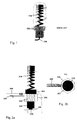
- Fig. 1 The figure shows a helix-type antenna element 110, connecting piece 120, and an antenna feed conductor 130.
- the element 110 is at its lower end attached to the connecting piece 120 which in turn can be screwed into the body or shell structure of the apparatus.
- the pitch or the distance between two successive turns, measured in the direction of the axis of the element, gets smaller approaching the upper end of the element.
- a pitch p1 is smaller than a pitch p2 at a lower point in the element.
- the feed conductor 130 is galvanically connected to the lower end of the helix element 110 and extends downwards through an axial hole in the connecting piece 120.
- the connecting piece may be conductive, but isolated from the helix, whereby it further serves as a shield for the end portion of the feed conductor.
- Fig. 1 further shows in dashed line also the outline of the protective hood of the antenna.
- All antenna elements resonate at a certain fundamental frequency and also at harmonic frequencies of the fundamental frequency.
- the fundamental frequency refers here to the frequency at which the electrical length of the antenna element equals a quarter of the wavelength. If the pitch in a helix antenna is uniform throughout, the harmonics are multiples of the fundamental frequency. If there are different pitches, the relation between the harmonics changes. By suitably selecting the number of turns and the pitches, among other things, it is possible to have such values for the resonance frequencies that the structure is applicable in the frequency bands of at least two radio systems.
- the fundamental frequency and its third harmonic are arranged at the desired locations on the frequency axis.
- the third harmonic means the third resonance frequency when the fundamental frequency is counted as the "first harmonic".
- An object of the invention is to reduce said drawbacks associated with the prior art.
- a structure according to the invention is characterized by that which is specified in the independent claim 1.
- the antenna structure has as its radiating elements not only the helix but also the joining piece that attaches the helix to the apparatus.
- the helix is designed such that the distance between its conductor turns varies.
- the electrical length of the joining piece is increased by means of a conductive projection, for example, which remains within the covering of the apparatus.
- An advantage of the invention is that it facilitates an antenna suitable for mobile stations, which antenna has more bands than prior-art antennas.
- Another advantage of the invention is that the production costs of the structure according to the invention are relatively small.
- Fig. 1 was already discussed in connection with the description of the prior art.
- Fig. 2a shows a side view of an example of the antenna structure according to the invention. It comprises a helix-type antenna element 210, joining piece 220, and antenna feed conductor 230. Like in the structure shown in Fig. 1, the pitch in the helix element gets smaller from the lower end to the upper end of the element. Terms “lower”, “upper”, “horizontal” and “vertical” refer in this description and in the claims to the position of the antenna structure as shown in Fig. 2, and they have nothing to do with the operating position of the antenna.
- the joining piece 220 comprises a top part 221, thread part 222, bottom part 223, connecting part 224, counterpart 225, and a projecting part 226. All these parts are conductive and in galvanic contact with each other.
- the horizontal projection 226 is attached by its one end to the counterpart 225. It may be e.g. a separate flat plate or just a metal plating on the inner surface of the covering.
- the counterpart has got inner threads.
- Fig. 2 it is a nut-like part attached to the dielectric covering 240 of the apparatus.
- the top part 221, thread part 222, bottom part 223 and connecting part 224 form an entity which is screwed into the counterpart 225.
- the helix element 210 is attached by its lower end to the top part of the joining piece 220.
- the connecting part 224 is the lowest part in the joining piece.
- the feed conductor 230 comprises a bent part exerting spring force against the connecting part 224 when the antenna is installed in the apparatus.
- Fig. 2b shows a bird's-eye view of the antenna structure of Fig. 2a. It reveals the width of the projection 226, the round shape of the cross-sections of the helix and the top part 221 of the joining piece, and the angular shape of the cross-section of the counterpart 225 for the joining piece.
- the joining piece of the helix may also function as a radiator. It is a conductive body connecting to the inner conductor 230 of the antenna feedline and does not have a conductive shield around it.
- the joining piece can be shortened in the vertical direction using a projection 226. The need for space for the strip-like projection in the upper part of the covering of the apparatus is insignificant.
- At the interface between the joining piece and the helix there is an electrical discontinuity. Therefore the helix resonates alone at certain frequencies and the joining piece resonates alone at certain other frequencies. In addition there is a frequency at which the helix and the joining piece resonate together. This common resonance frequency is the lowest of the resonance frequencies of the structure.
- the fundamental resonance frequency of the joining piece and one or more of the harmonics of the helix for example.
- the structure according to the invention goes farther than prior-art structures: the variation in the helix pitch can be arranged such that the ratios of the third, fifth and, if necessary, the seventh harmonic and the fundamental frequency are as desired.
- Fig. 3 shows a second example of the structure according to the invention.
- the difference from the structure of Fig. 2 is that the joining piece is now horizontal so that the helix element 310 is connected to its end from the side.
- the joining piece does not have a projection like the projecting part 226 in Fig. 2. This means that the joining piece has to be made longer if the antenna is to function at the same frequencies as the structure of Fig. 2.
- Fig. 4 shows a third example of the structure according to the invention.
- the helix element 410 and joining piece 420 have a common axis, like in Fig. 2.
- the counterpart 425 of the joining piece does not include a projection.
- the counterpart itself is, however, larger than in the structure of Fig. 2.
- the purpose of the larger size is the same as that of the projection: to achieve a certain electrical length for the joining piece with a smaller vertical physical length.
- Fig. 5 shows examples of the frequency characteristics of an antenna according to the invention. It shows, as the function of frequency, the reflection coefficient S11 of two antennas, both of which are in accordance with Fig. 2 as to their structure. Six resonance points can be seen in the first curve 51. If a criterion for a viable frequency band is that the reflection coefficient is below, say, -5dB, the structure represented by curve 51 functions as an antenna in four frequency bands: 430-480 MHz, 860-950 MHz, 1240-1280 MHz and 1550-2230 MHz. The frequencies used by the future GSM450 system fall into the first frequency band of these. The frequencies used by the GSM900 system fall into the second frequency band of those above.
- the third band can be utilized in the GPS (global positioning system) which uses the 1227.6 MHz frequency.
- the frequencies used by the GSM1800, PCS1900 and WCDMA systems fall into the fourth, very wide, band.
- the GPS frequency 1575.42 MHz falls into that same band.
- the first band 430-480 MHz is based on the common resonance of the helix element and the joining piece of the antenna.
- the second band 860-950 MHz is based on the third harmonic of the fundamental resonance frequency of the helix element. This is arranged a little above 900 MHz by suitably decreasing the pitch of the helix approaching the upper end of the helix.
- the fourth band 1550-2230 MHz is produced by arranging at suitable points three resonance frequencies: the fifth harmonic of the helix, the fundamental frequency of the joining piece and the seventh harmonic of the helix.
- the fifth and seventh harmonics of the helix as well as the aforementioned third harmonic have been pulled downwards by making the thread suitably more dense going up.
- the second curve 52 is similar to curve 51.
- slightly changing the dimensions the second band of the antenna, for example, has been arranged so as to better fall into the band used by the GSM900 system.
- Fig. 6 shows a mobile station MS. It has an antenna 600 according to the invention with the helix element 610 of the antenna residing outside the covering of the mobile station and the joining piece 620 residing inside the covering.
Landscapes
- Engineering & Computer Science (AREA)
- Computer Networks & Wireless Communication (AREA)
- Waveguide Aerials (AREA)
- Details Of Aerials (AREA)
- Support Of Aerials (AREA)
Applications Claiming Priority (2)
| Application Number | Priority Date | Filing Date | Title |
|---|---|---|---|
| FI20001387 | 2000-06-12 | ||
| FI20001387A FI113220B (fi) | 2000-06-12 | 2000-06-12 | Monikaista-antenni |
Publications (1)
| Publication Number | Publication Date |
|---|---|
| EP1164657A1 true EP1164657A1 (de) | 2001-12-19 |
Family
ID=8558535
Family Applications (1)
| Application Number | Title | Priority Date | Filing Date |
|---|---|---|---|
| EP01660108A Withdrawn EP1164657A1 (de) | 2000-06-12 | 2001-06-06 | Multiband-Antenne |
Country Status (4)
| Country | Link |
|---|---|
| US (1) | US6473056B2 (de) |
| EP (1) | EP1164657A1 (de) |
| CN (1) | CN1213511C (de) |
| FI (1) | FI113220B (de) |
Cited By (3)
| Publication number | Priority date | Publication date | Assignee | Title |
|---|---|---|---|---|
| KR20030077770A (ko) * | 2002-03-27 | 2003-10-04 | 삼성전기주식회사 | 트리플 밴드 스터비 안테나 |
| EP1435136A1 (de) * | 2001-10-13 | 2004-07-07 | Samsung Electronics Co., Ltd. | Mobilkommunikationssystem mit einer mehrbandantenne |
| EP1938423A1 (de) * | 2005-09-23 | 2008-07-02 | Ace Antenna Corp. | Chipantenne |
Families Citing this family (44)
| Publication number | Priority date | Publication date | Assignee | Title |
|---|---|---|---|---|
| CN1989652B (zh) | 2004-06-28 | 2013-03-13 | 脉冲芬兰有限公司 | 天线部件 |
| KR100638621B1 (ko) * | 2004-10-13 | 2006-10-26 | 삼성전기주식회사 | 광대역 내장형 안테나 |
| DE102004054466A1 (de) * | 2004-11-11 | 2006-06-08 | Robert Bosch Gmbh | Radarsystem insbesondere zur Entfernungs- und/oder Geschwindigkeitsmessung |
| US7202836B2 (en) * | 2005-05-06 | 2007-04-10 | Motorola, Inc. | Antenna apparatus and method of forming same |
| FI20055420A0 (fi) | 2005-07-25 | 2005-07-25 | Lk Products Oy | Säädettävä monikaista antenni |
| FI119009B (fi) * | 2005-10-03 | 2008-06-13 | Pulse Finland Oy | Monikaistainen antennijärjestelmä |
| FI119535B (fi) * | 2005-10-03 | 2008-12-15 | Pulse Finland Oy | Monikaistainen antennijärjestelmä |
| FI118782B (fi) | 2005-10-14 | 2008-03-14 | Pulse Finland Oy | Säädettävä antenni |
| US8618990B2 (en) | 2011-04-13 | 2013-12-31 | Pulse Finland Oy | Wideband antenna and methods |
| EP2092607A4 (de) * | 2006-10-05 | 2012-12-19 | Pulse Finland Oy | Mehrbandantenne mit einer gemeinsamen resonanz-zuführungsstruktur und verfahren |
| US10211538B2 (en) | 2006-12-28 | 2019-02-19 | Pulse Finland Oy | Directional antenna apparatus and methods |
| FI20075269A0 (fi) | 2007-04-19 | 2007-04-19 | Pulse Finland Oy | Menetelmä ja järjestely antennin sovittamiseksi |
| FI120427B (fi) | 2007-08-30 | 2009-10-15 | Pulse Finland Oy | Säädettävä monikaista-antenni |
| FI124129B (fi) * | 2007-09-28 | 2014-03-31 | Pulse Finland Oy | Kaksoisantenni |
| EP2461421B1 (de) * | 2009-07-31 | 2019-03-13 | Hytera Communications Corp., Ltd. | Zweifrequenz-antenne |
| FI20096134A0 (fi) | 2009-11-03 | 2009-11-03 | Pulse Finland Oy | Säädettävä antenni |
| FI20096251A0 (sv) | 2009-11-27 | 2009-11-27 | Pulse Finland Oy | MIMO-antenn |
| US8847833B2 (en) | 2009-12-29 | 2014-09-30 | Pulse Finland Oy | Loop resonator apparatus and methods for enhanced field control |
| FI20105158A (fi) | 2010-02-18 | 2011-08-19 | Pulse Finland Oy | Kuorisäteilijällä varustettu antenni |
| US9406998B2 (en) | 2010-04-21 | 2016-08-02 | Pulse Finland Oy | Distributed multiband antenna and methods |
| FI20115072A0 (fi) | 2011-01-25 | 2011-01-25 | Pulse Finland Oy | Moniresonanssiantenni, -antennimoduuli ja radiolaite |
| US9673507B2 (en) | 2011-02-11 | 2017-06-06 | Pulse Finland Oy | Chassis-excited antenna apparatus and methods |
| US8648752B2 (en) | 2011-02-11 | 2014-02-11 | Pulse Finland Oy | Chassis-excited antenna apparatus and methods |
| US8866689B2 (en) | 2011-07-07 | 2014-10-21 | Pulse Finland Oy | Multi-band antenna and methods for long term evolution wireless system |
| US9450291B2 (en) | 2011-07-25 | 2016-09-20 | Pulse Finland Oy | Multiband slot loop antenna apparatus and methods |
| US9123990B2 (en) | 2011-10-07 | 2015-09-01 | Pulse Finland Oy | Multi-feed antenna apparatus and methods |
| US9531058B2 (en) | 2011-12-20 | 2016-12-27 | Pulse Finland Oy | Loosely-coupled radio antenna apparatus and methods |
| US9484619B2 (en) | 2011-12-21 | 2016-11-01 | Pulse Finland Oy | Switchable diversity antenna apparatus and methods |
| US8988296B2 (en) | 2012-04-04 | 2015-03-24 | Pulse Finland Oy | Compact polarized antenna and methods |
| US9979078B2 (en) | 2012-10-25 | 2018-05-22 | Pulse Finland Oy | Modular cell antenna apparatus and methods |
| US10069209B2 (en) | 2012-11-06 | 2018-09-04 | Pulse Finland Oy | Capacitively coupled antenna apparatus and methods |
| US10079428B2 (en) | 2013-03-11 | 2018-09-18 | Pulse Finland Oy | Coupled antenna structure and methods |
| US9647338B2 (en) | 2013-03-11 | 2017-05-09 | Pulse Finland Oy | Coupled antenna structure and methods |
| CN104167593A (zh) * | 2013-05-16 | 2014-11-26 | 杜立茹 | 螺旋天线 |
| US9634383B2 (en) | 2013-06-26 | 2017-04-25 | Pulse Finland Oy | Galvanically separated non-interacting antenna sector apparatus and methods |
| US20150138020A1 (en) * | 2013-11-15 | 2015-05-21 | Motorola Solutions, Inc | Intrinsically safe housing and antenna design for a radio device and method of forming same |
| US9680212B2 (en) | 2013-11-20 | 2017-06-13 | Pulse Finland Oy | Capacitive grounding methods and apparatus for mobile devices |
| US9590308B2 (en) | 2013-12-03 | 2017-03-07 | Pulse Electronics, Inc. | Reduced surface area antenna apparatus and mobile communications devices incorporating the same |
| US9350081B2 (en) | 2014-01-14 | 2016-05-24 | Pulse Finland Oy | Switchable multi-radiator high band antenna apparatus |
| US9948002B2 (en) | 2014-08-26 | 2018-04-17 | Pulse Finland Oy | Antenna apparatus with an integrated proximity sensor and methods |
| US9973228B2 (en) | 2014-08-26 | 2018-05-15 | Pulse Finland Oy | Antenna apparatus with an integrated proximity sensor and methods |
| US9722308B2 (en) | 2014-08-28 | 2017-08-01 | Pulse Finland Oy | Low passive intermodulation distributed antenna system for multiple-input multiple-output systems and methods of use |
| US9906260B2 (en) | 2015-07-30 | 2018-02-27 | Pulse Finland Oy | Sensor-based closed loop antenna swapping apparatus and methods |
| CN216413259U (zh) * | 2021-06-07 | 2022-04-29 | 广州中海达卫星导航技术股份有限公司 | 宽带化螺旋天线 |
Citations (6)
| Publication number | Priority date | Publication date | Assignee | Title |
|---|---|---|---|---|
| US3852759A (en) * | 1960-04-01 | 1974-12-03 | Itt | Broadband tunable antenna |
| US4169267A (en) * | 1978-06-19 | 1979-09-25 | The United States Of America As Represented By The Secretary Of The Air Force | Broadband helical antennas |
| US5329287A (en) * | 1992-02-24 | 1994-07-12 | Cal Corporation | End loaded helix antenna |
| EP0736926A1 (de) * | 1995-04-07 | 1996-10-09 | Lk-Products Oy | Wendelantenne und Herstellungsverfahren |
| US5892480A (en) * | 1997-04-09 | 1999-04-06 | Harris Corporation | Variable pitch angle, axial mode helical antenna |
| WO1999063626A2 (en) * | 1998-06-01 | 1999-12-09 | Byunghoon Ryou | Antenna connector for radio communication equipment |
Family Cites Families (8)
| Publication number | Priority date | Publication date | Assignee | Title |
|---|---|---|---|---|
| SE512062C2 (sv) * | 1993-07-14 | 2000-01-17 | Ericsson Ge Mobile Communicat | Förfarande och anordning för att förbättra effektivitet och bandbredd för en antenn på en bärbar utrustning |
| US6025816A (en) * | 1996-12-24 | 2000-02-15 | Ericsson Inc. | Antenna system for dual mode satellite/cellular portable phone |
| US5914689A (en) * | 1997-06-25 | 1999-06-22 | Centurion Intl., Inc. | Antenna for a portable, wireless communication device |
| GB2328084A (en) | 1997-07-31 | 1999-02-10 | Whitaker Corp | Multiple coil wide band antenna |
| KR100306274B1 (ko) | 1998-02-20 | 2001-09-26 | 윤종용 | 무선 송수신기를 위한 이중 대역 안테나 |
| JPH11355029A (ja) | 1998-06-12 | 1999-12-24 | Smk Corp | アンテナ装置 |
| GB2351849A (en) | 1999-05-27 | 2001-01-10 | Motorola Inc | Multi-band helical antenna with varying pitch |
| US6275198B1 (en) * | 2000-01-11 | 2001-08-14 | Motorola, Inc. | Wide band dual mode antenna |
-
2000
- 2000-06-12 FI FI20001387A patent/FI113220B/fi active
-
2001
- 2001-06-06 EP EP01660108A patent/EP1164657A1/de not_active Withdrawn
- 2001-06-11 US US09/879,735 patent/US6473056B2/en not_active Expired - Fee Related
- 2001-06-12 CN CNB011210893A patent/CN1213511C/zh not_active Expired - Fee Related
Patent Citations (6)
| Publication number | Priority date | Publication date | Assignee | Title |
|---|---|---|---|---|
| US3852759A (en) * | 1960-04-01 | 1974-12-03 | Itt | Broadband tunable antenna |
| US4169267A (en) * | 1978-06-19 | 1979-09-25 | The United States Of America As Represented By The Secretary Of The Air Force | Broadband helical antennas |
| US5329287A (en) * | 1992-02-24 | 1994-07-12 | Cal Corporation | End loaded helix antenna |
| EP0736926A1 (de) * | 1995-04-07 | 1996-10-09 | Lk-Products Oy | Wendelantenne und Herstellungsverfahren |
| US5892480A (en) * | 1997-04-09 | 1999-04-06 | Harris Corporation | Variable pitch angle, axial mode helical antenna |
| WO1999063626A2 (en) * | 1998-06-01 | 1999-12-09 | Byunghoon Ryou | Antenna connector for radio communication equipment |
Cited By (5)
| Publication number | Priority date | Publication date | Assignee | Title |
|---|---|---|---|---|
| EP1435136A1 (de) * | 2001-10-13 | 2004-07-07 | Samsung Electronics Co., Ltd. | Mobilkommunikationssystem mit einer mehrbandantenne |
| EP1435136A4 (de) * | 2001-10-13 | 2005-02-09 | Samsung Electronics Co Ltd | Mobilkommunikationssystem mit einer mehrbandantenne |
| KR20030077770A (ko) * | 2002-03-27 | 2003-10-04 | 삼성전기주식회사 | 트리플 밴드 스터비 안테나 |
| EP1938423A1 (de) * | 2005-09-23 | 2008-07-02 | Ace Antenna Corp. | Chipantenne |
| EP1938423A4 (de) * | 2005-09-23 | 2008-11-26 | Ace Antenna Corp | Chipantenne |
Also Published As
| Publication number | Publication date |
|---|---|
| US6473056B2 (en) | 2002-10-29 |
| US20010050656A1 (en) | 2001-12-13 |
| CN1336700A (zh) | 2002-02-20 |
| FI113220B (fi) | 2004-03-15 |
| FI20001387A0 (fi) | 2000-06-12 |
| FI20001387A (fi) | 2001-12-13 |
| CN1213511C (zh) | 2005-08-03 |
Similar Documents
| Publication | Publication Date | Title |
|---|---|---|
| US6473056B2 (en) | Multiband antenna | |
| US7180455B2 (en) | Broadband internal antenna | |
| US6246371B1 (en) | Wide band antenna means incorporating a radiating structure having a band form | |
| US6646606B2 (en) | Double-action antenna | |
| US6922171B2 (en) | Planar antenna structure | |
| US9246210B2 (en) | Antenna with cover radiator and methods | |
| US9979086B2 (en) | Multiband antenna assemblies | |
| US8552918B2 (en) | Multiband high gain omnidirectional antennas | |
| EP1791213A1 (de) | Mehrbandantenne | |
| EP1846982A1 (de) | Intern-monopol-antenne | |
| CN107210531B (zh) | 具有开口端迹线的偶极子天线元件 | |
| WO2008081077A1 (en) | Antenna structure | |
| US6628241B1 (en) | Antenna device and communication terminal comprising the same | |
| US20210119335A1 (en) | Antenna device | |
| US7545330B2 (en) | Antenna device including surface-mounted element | |
| KR100766784B1 (ko) | 안테나 | |
| CN101471484B (zh) | 一种多频天线 | |
| WO2010077574A2 (en) | Multiband high gain omnidirectional antennas | |
| CN104901015A (zh) | 一种兼顾窄边框与多频段覆盖的移动终端用lte天线 | |
| WO2001020716A1 (en) | Antenna arrangement and a method for reducing size of a whip element in an antenna arrangement | |
| CN114696073A (zh) | 天线系统 | |
| KR100649492B1 (ko) | 이동통신 단말기의 다중 대역 내장형 안테나 | |
| WO2007054616A1 (en) | Internal monopole antenna | |
| WO2023208576A1 (en) | Antenna arrangement for mimo antenna applications | |
| US20040233113A1 (en) | Multi band low frequency phone and antenna design |
Legal Events
| Date | Code | Title | Description |
|---|---|---|---|
| PUAI | Public reference made under article 153(3) epc to a published international application that has entered the european phase |
Free format text: ORIGINAL CODE: 0009012 |
|
| AK | Designated contracting states |
Kind code of ref document: A1 Designated state(s): DE DK FR GB SE Kind code of ref document: A1 Designated state(s): AT BE CH CY DE DK ES FI FR GB GR IE IT LI LU MC NL PT SE TR |
|
| AX | Request for extension of the european patent |
Free format text: AL;LT;LV;MK;RO;SI |
|
| 17P | Request for examination filed |
Effective date: 20020321 |
|
| AKX | Designation fees paid |
Free format text: DE DK FR GB SE |
|
| 17Q | First examination report despatched |
Effective date: 20040503 |
|
| RAP1 | Party data changed (applicant data changed or rights of an application transferred) |
Owner name: LK PRODUCTS OY |
|
| RAP1 | Party data changed (applicant data changed or rights of an application transferred) |
Owner name: PULSE FINLAND OY |
|
| APBN | Date of receipt of notice of appeal recorded |
Free format text: ORIGINAL CODE: EPIDOSNNOA2E |
|
| APBR | Date of receipt of statement of grounds of appeal recorded |
Free format text: ORIGINAL CODE: EPIDOSNNOA3E |
|
| APAF | Appeal reference modified |
Free format text: ORIGINAL CODE: EPIDOSCREFNE |
|
| APBT | Appeal procedure closed |
Free format text: ORIGINAL CODE: EPIDOSNNOA9E |
|
| GRAP | Despatch of communication of intention to grant a patent |
Free format text: ORIGINAL CODE: EPIDOSNIGR1 |
|
| STAA | Information on the status of an ep patent application or granted ep patent |
Free format text: STATUS: THE APPLICATION IS DEEMED TO BE WITHDRAWN |
|
| 18D | Application deemed to be withdrawn |
Effective date: 20111018 |