EP1152258B1 - Low-cost radar, in particular for high-resolution imaging - Google Patents
Low-cost radar, in particular for high-resolution imaging Download PDFInfo
- Publication number
- EP1152258B1 EP1152258B1 EP01400949A EP01400949A EP1152258B1 EP 1152258 B1 EP1152258 B1 EP 1152258B1 EP 01400949 A EP01400949 A EP 01400949A EP 01400949 A EP01400949 A EP 01400949A EP 1152258 B1 EP1152258 B1 EP 1152258B1
- Authority
- EP
- European Patent Office
- Prior art keywords
- reception
- radar
- radar according
- antenna
- antennas
- Prior art date
- Legal status (The legal status is an assumption and is not a legal conclusion. Google has not performed a legal analysis and makes no representation as to the accuracy of the status listed.)
- Expired - Lifetime
Links
Images

Classifications
-
- G—PHYSICS
- G01—MEASURING; TESTING
- G01S—RADIO DIRECTION-FINDING; RADIO NAVIGATION; DETERMINING DISTANCE OR VELOCITY BY USE OF RADIO WAVES; LOCATING OR PRESENCE-DETECTING BY USE OF THE REFLECTION OR RERADIATION OF RADIO WAVES; ANALOGOUS ARRANGEMENTS USING OTHER WAVES
- G01S7/00—Details of systems according to groups G01S13/00, G01S15/00, G01S17/00
- G01S7/02—Details of systems according to groups G01S13/00, G01S15/00, G01S17/00 of systems according to group G01S13/00
- G01S7/35—Details of non-pulse systems
- G01S7/352—Receivers
-
- G—PHYSICS
- G01—MEASURING; TESTING
- G01S—RADIO DIRECTION-FINDING; RADIO NAVIGATION; DETERMINING DISTANCE OR VELOCITY BY USE OF RADIO WAVES; LOCATING OR PRESENCE-DETECTING BY USE OF THE REFLECTION OR RERADIATION OF RADIO WAVES; ANALOGOUS ARRANGEMENTS USING OTHER WAVES
- G01S13/00—Systems using the reflection or reradiation of radio waves, e.g. radar systems; Analogous systems using reflection or reradiation of waves whose nature or wavelength is irrelevant or unspecified
- G01S13/88—Radar or analogous systems specially adapted for specific applications
- G01S13/89—Radar or analogous systems specially adapted for specific applications for mapping or imaging
-
- G—PHYSICS
- G01—MEASURING; TESTING
- G01S—RADIO DIRECTION-FINDING; RADIO NAVIGATION; DETERMINING DISTANCE OR VELOCITY BY USE OF RADIO WAVES; LOCATING OR PRESENCE-DETECTING BY USE OF THE REFLECTION OR RERADIATION OF RADIO WAVES; ANALOGOUS ARRANGEMENTS USING OTHER WAVES
- G01S7/00—Details of systems according to groups G01S13/00, G01S15/00, G01S17/00
- G01S7/02—Details of systems according to groups G01S13/00, G01S15/00, G01S17/00 of systems according to group G01S13/00
- G01S7/03—Details of HF subsystems specially adapted therefor, e.g. common to transmitter and receiver
- G01S7/032—Constructional details for solid-state radar subsystems
-
- H—ELECTRICITY
- H01—ELECTRIC ELEMENTS
- H01Q—ANTENNAS, i.e. RADIO AERIALS
- H01Q21/00—Antenna arrays or systems
- H01Q21/0006—Particular feeding systems
- H01Q21/0075—Stripline fed arrays
-
- H—ELECTRICITY
- H01—ELECTRIC ELEMENTS
- H01Q—ANTENNAS, i.e. RADIO AERIALS
- H01Q21/00—Antenna arrays or systems
- H01Q21/06—Arrays of individually energised antenna units similarly polarised and spaced apart
- H01Q21/061—Two dimensional planar arrays
- H01Q21/065—Patch antenna array
-
- H—ELECTRICITY
- H01—ELECTRIC ELEMENTS
- H01Q—ANTENNAS, i.e. RADIO AERIALS
- H01Q3/00—Arrangements for changing or varying the orientation or the shape of the directional pattern of the waves radiated from an antenna or antenna system
- H01Q3/26—Arrangements for changing or varying the orientation or the shape of the directional pattern of the waves radiated from an antenna or antenna system varying the relative phase or relative amplitude of energisation between two or more active radiating elements; varying the distribution of energy across a radiating aperture
- H01Q3/2605—Array of radiating elements provided with a feedback control over the element weights, e.g. adaptive arrays
- H01Q3/2611—Means for null steering; Adaptive interference nulling
-
- G—PHYSICS
- G01—MEASURING; TESTING
- G01S—RADIO DIRECTION-FINDING; RADIO NAVIGATION; DETERMINING DISTANCE OR VELOCITY BY USE OF RADIO WAVES; LOCATING OR PRESENCE-DETECTING BY USE OF THE REFLECTION OR RERADIATION OF RADIO WAVES; ANALOGOUS ARRANGEMENTS USING OTHER WAVES
- G01S13/00—Systems using the reflection or reradiation of radio waves, e.g. radar systems; Analogous systems using reflection or reradiation of waves whose nature or wavelength is irrelevant or unspecified
- G01S13/88—Radar or analogous systems specially adapted for specific applications
- G01S13/93—Radar or analogous systems specially adapted for specific applications for anti-collision purposes
- G01S13/931—Radar or analogous systems specially adapted for specific applications for anti-collision purposes of land vehicles
-
- G—PHYSICS
- G01—MEASURING; TESTING
- G01S—RADIO DIRECTION-FINDING; RADIO NAVIGATION; DETERMINING DISTANCE OR VELOCITY BY USE OF RADIO WAVES; LOCATING OR PRESENCE-DETECTING BY USE OF THE REFLECTION OR RERADIATION OF RADIO WAVES; ANALOGOUS ARRANGEMENTS USING OTHER WAVES
- G01S7/00—Details of systems according to groups G01S13/00, G01S15/00, G01S17/00
- G01S7/02—Details of systems according to groups G01S13/00, G01S15/00, G01S17/00 of systems according to group G01S13/00
- G01S7/03—Details of HF subsystems specially adapted therefor, e.g. common to transmitter and receiver
- G01S7/038—Feedthrough nulling circuits
Definitions
- the present invention relates to a low-cost radar, especially high-resolution imaging. It applies in particular for short-range surveillance radars such as, for example, crossroads or parking level crossing surveillance.
- the electronic scanning radars make it possible to obtain an almost simultaneous vision of the observed scene.
- they implement complex electronic circuits and require very strong manufacturing constraints, related to the control of the phase and the amplitude on each radiating element of the antenna, which makes them expensive and limits their field of action. application.
- Computational radars provide an instantaneous view of the observed scene.
- the control of the phase and amplitude on each element of the receiving antenna is performed directly by the beamforming algorithm by calculation and antenna dispersions and analogue reception channels can be compensated by this processing.
- these radars use heterodyne reception.
- each element of the receiving antenna is followed by a complex reception chain comprising, in particular, mixing, amplification, filtering and coding means. The cost of this type of radar is therefore high.
- a patent application EP-A-0 919 828 discloses a radar system comprising means for forming a transmission beam associated with a plurality of antenna elements.
- An object of the invention is to allow the realization of an economic imaging radar of the beam-forming type by calculation.
- the object of the invention is a radar which comprises means for beamforming by the calculation associated with N homodyne reception channels, each channel providing a reception signal to the beam forming means by the computation, the transmitting antenna being arranged such that its distance increases from one receiving antenna to the next.
- the spacing between the antennas is defined to direct homodyne leakage in a direction located in an angular area of space that is not handled by the radar.
- the distance of the transmitting antenna increases for example regularly from one receiving antenna to the next.
- the antennas of the reception channels are for example aligned with a substantially constant space d between two consecutive antennas.
- the radar exploits the homodyne leak to perform a self-test of the transmission-reception function.
- the receiving antennas are for example made on the same printed circuit.
- the main advantages of the invention are that it allows a high resolution over a wide frequency band, that it adapts to many applications, that it allows a very good reproducibility of manufacture, that it allows a great safety of operation, and that it allows a modular operation of the radar.
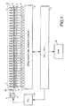
- FIG. 1 presents by a block diagram a possible embodiment of a radar according to the invention, having for example an imaging function. It is a computed beamforming radar having a homodyne reception.
- the reception chain is then reduced to a demodulation of the signal received by each elementary antenna by the local oscillator of transmission, filtering, amplification and coding.
- the reception being done in baseband, it is then possible to use components of very wide diffusion and low cost for the reception chain.
- Such reception may nevertheless have a deterrent disadvantage for radar surveillance use, it is the degradation of the sensitivity of the radar due to homodynes leakage. This loss of sensitivity is particularly present at a short distance, which corresponds to the case of use of the radar for proximity monitoring such as, for example, level crossing or intersection surveillance.
- the invention overcomes the aforementioned disadvantage by advantageously providing a homodyne leak compression in a given direction, thus controllable.
- a radar according to the invention as represented by FIG. 1 comprises several reception channels in parallel for beamforming by calculation.
- a reception channel comprises an elementary reception antenna 1, a microwave mixer 2, an amplifier 3 and an analog-digital converter 4. More particularly, an elementary antenna 1 is connected to a first input of a mixer 2. The second input from it receives the signal produced by the local emission oscillator 5. Since the radar is of the homodyne type, there is no transposition of frequency at an intermediate frequency.
- the output of the mixer thus comprising the reception signal demodulated by the local oscillator signal, is connected to the input of an amplifier 3 whose output is connected to the input of a converter 4.
- the latter converts the analog reception signal in a digital signal intended in particular to be processed by the calculation means for beamforming by calculation, hereinafter called FFC.
- the 32 digital signals coming from the 32 reception channels are for example processed by means 6 for serializing the data.
- the 32 parallel signals are for example put in series to be transmitted to the beam forming means 7 by the calculation, FFC.
- These means are made in a known manner based on signal processing processors.
- These means are also associated, for example on the same hardware circuits FFT Fast Fourier Transform calculation means, as well as other radar processing means known elsewhere.
- These latter for example, supply, for example, the radar waveform digital control transmitted to the local oscillator 5 via a phase-locked loop 8, also called PLL according to the initials of the Anglo-Saxon expression.
- the generated waveform 9 is for example that of a FMCW radar, that is to say a continuous waveform whose frequency is modulated linearly by rising or falling ramps. Other waveforms are possible, for example of the frequency hopping type.
- the radar processing means 7 are for example connected to a man-machine interface 10 intended in particular to exploit the radar image.
- the output of the local oscillator is connected to a transmitting antenna 11.
- This local oscillator has as output a signal powerful enough for the transmission, but also for supplying the 32 mixers 2.
- the transmitting antenna is discarded from the receiving antennas so as not to disturb the reception.
- Each antenna 1, 11 for receiving and transmitting for example consists of two pellets, also called patches in the Anglo-Saxon literature.
- the receiving antennas 1 are for example made on the same printed circuit 12.
- the mixing circuits 2 are also made on the same printed circuit. With a few precautions, the transmitting antenna can also be made on this printed circuit.
- FIG. 2 illustrates the resolution obtained by FFC as well as the reception angular domain, in the case of use of 32 reception channels.
- the FFC allows the calculation of 32 overlapping elementary beams 21.
- the angular width occupied by these 32 elementary beams is for example of the order of 60 °, corresponding to the angle of action of the radar.
- the resolution corresponds to the width of an elementary beam reduced by its overlapping areas, which corresponds, for example, to an angle of the order 3.5 °, characterizing the resolution of the radar.
- An FFC radar therefore makes it possible to obtain a high resolution over a wide angular range provided that sufficient reception channels are provided.
- the homodyne reception technique is also economical, since it avoids a certain complexity of circuits and makes it possible to use components of large diffusion and therefore of low cost for the reception chain.
- the costs are further reduced by realizing part of the reception circuits, in particular the elementary antennas 1 and the mixer circuits 2 by the printed circuit technique.
- the conductive areas constituting the antennas 1, the mixers 2 and the microwave lines can in fact be obtained by chemical machining on an organic support according to the conventional technique of the printed circuit which is well tested and inexpensive. In addition to the economic aspect, it also results in a very good reproducibility of parts and high reliability of operation.
- the reduction of costs can also be continued by printing all the elements, that is to say the antennas, the mixers and the microwave lines, on the same face of the support. This also avoids the performing a large number of crossings for microwave signals on the printed circuit. These traverses are thus reduced to the only passage of the signal supplied by the local oscillator 5 and possibly to the transmission signals if the transmitting antenna is also present on the printed
- the invention thus makes it possible to obtain an economical high resolution imaging radar.
- the invention makes it possible to control homodyne leaks, which are disturbing to reception.
- FIG. 3 illustrates an arrangement of receiving antennas which makes it possible to reject these leaks in a given direction, and thus to control them.
- the reception antennas denoted AR 1 , AR 2 ,... AR i , AR i + 1 , ... AR N , are aligned regularly, that is to say with a substantially constant space d between two consecutive antennas antennas.
- the transmitting antenna AE is for example aligned with the receiving antennas without being mixed. It is at least arranged so that its distance increases regularly from one receiving antenna to another, that is to say that its distance increases for example in a constant pitch.
- the receiving antenna is at any distance D of a first antenna AR 1 , then at a distance D + d of a second antenna AR 2 , then at a distance D + 2d a third receiving antenna and so on.
- the transmitting antenna AE radiates a microwave signal s (t) accompanied by a limited band noise representing the homodyne leak, to the reception antennas by coupling.
- the coupling occurs in the air but also between the microwave transmission and reception lines.
- the reception being of the homodyne and non-heterodyne type, there is no frequency transposition making it possible to overcome this radiated noise.
- the captured homodyne leak is therefore the same for all the antennas, with the delay ⁇ near, which is constant from one antenna to the next.
- the homodyne leak is picked up by the antennas in an apparent direction 31 which is perfectly defined as a function of the delays ⁇ . It is therefore possible to choose the spacing between the antennas so as to orient the homodyne leak in a given apparent direction.
- This apparent direction depends on the actual direction of arrival of the leak and the ambiguity diagram of the network. For example, for an antenna whose source of emission and the sources or antennas of reception are aligned, the direction of arrival of the leak is close to 90 °. This leak is not seen directly.
- the noise that accompanies the leak is generally narrowband and therefore undergoes the same processing, which amounts to concentrating it in a particular direction which, preferably, will not be exploited by the radar in operational mode. It can however be used to perform a self-test of the transmission-reception function, without the addition of complementary circuits, the adaptations being only software. A radar according to the invention can therefore economically and simply exploit the leak to perform a self-test of the transmission and reception functions.
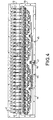
- FIG. 4 illustrates a possible embodiment of receiving antennas and mixers.
- This embodiment still includes 32 channels as an example.
- Antennas and microwave lines are printed on a support 12, for example organic epoxy type. Of Preferably, all these elements are printed on the same face of the support, the other face being covered with a ground plane.
- the antennas are aligned at a substantially constant distance from one antenna to the next.
- Each elementary reception antenna comprises for example two pellets 41, 42 connected in parallel to a microwave line 43. The latter connects the antennas to its mixer circuit 2.
- an electromagnetic shield protects the latter from external radiation.
- a metal strip 44 surrounds the mixing circuits. This metal strip is cut at the places where the microwave link lines 43 pass to the antennas.
- a not shown metal cover then covers the mixers, the edges of the cover being placed in contact with the metal strip 44. Holes 45, threaded or not, are for example provided to allow the attachment of the cover on the support 12.
- the for example, the internal space between the cover and the printed circuit is filled with absorbent foam, in particular to avoid electromagnetic coupling between the different microwave lines.
- the local oscillator signal is supplied to the mixers by a printed microwave line 46, which is subdivided into successive branches, each branch dividing for example in two, so that the microwave line length between the local oscillator and a mixer is the same for all mixers, especially for the purpose that the demodulation signals present on the mixers are all synchronous.
- a hole 47 makes it possible, for example, to pass a cable carrying the microwave signal produced by the local oscillator, the core of the cable being for example welded on the microwave line 46 printed on the support 12.
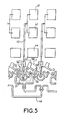
- FIG. 5 illustrates, by an enlarged view, an embodiment of the mixers 2, one input receiving the signal picked up by the associated elementary antenna and the other input receiving the demodulation signal supplied by the local oscillator 5.
- the output of the mixer attacks the input of amplifier 3 of the receive channel.
- An elementary antenna of a reception channel comprises, for example, two pellets 41, 42.
- the signal picked up by this elementary antenna transits via a microwave link 43 to the mixer 2.
- the mixer used is, for example, a balanced mixer which comprises two diodes, not shown, mounted head-to-tail at the output of a 0/180 ° wideband hybrid ring 51.
- Three quarter-wave lines 52, 53, 54 serve, for example, to mass return to the diodes.
- the wavelength considered is the wavelength at the central frequency.
- a first quarter-wave line 52 separates a first ground point, represented by a metallized hole 55, from the cathode of the first diode.
- a second quarter-wave line 53 separates the anode from the first diode of the cathode from the second diode.
- a third quarter-wave line separates the cathode of the second diode from a ground point, represented by a metallized hole 56.
- the two diodes are connected on the line 43 connecting the pellets 41, 42 to the mixer and conveying the signal detected.
- Filter elements 57, 58 isolate the detected signal from the output signal of the mixer.
- the output of the mixer is materialized by a connection point 59 connected to the input of the mixer 3.
- the printed circuit 12 on which the elementary antennas 1 and the microwave lines are made can be fixed on one face of a plate.
- On the other side of the plate can be arranged in particular the amplifiers (3), the analog-digital converters 4, the serialization means 6, the radar processing means 7, the phase-locked loop 8 as well as the Local oscillator 5.
- These means are supported by printed circuits which are for example themselves fixed on the plate.
- the plate equipped with these different circuits can be protected by an envelope provided with a microwave window facing antennas AE, 1.
- the radar thus obtained can have a height of the order of 20 cm, a depth of 10 cm and a width of 80 cm, for a weight of about 8 kg.
- FIG. 6 illustrates, by a synoptic, another advantage of a radar according to the invention. It's about its modularity. Several radars according to the invention can in fact be wired in parallel in order to obtain a radar of greater resolution or greater angular range of action.
- a radar as described according to the preceding figures therefore represents a module 61.
- a first module acts as a pilot module.
- its local oscillator 5 also controls all the other modules.
- each module comprises an input amplifier 62 for allowing the signal produced by the oscillator of the first module to control all other modules.
- the radar constituted by all the modules also comprises only one active AE transmit antenna, which is for example that of the first module, this antenna being powered by the local oscillator of this first module.
- the transmit antennas and local oscillators of the other modules can therefore remain inactive.
- all the modules are for example identical.
- the output of the amplification circuit 62 of the local oscillator signal which supplies the reception circuits of the first module furthermore attacks the input of the amplification circuit 62 of the second module and so on.
- the radar processing circuits 6, 7, in particular the FFC circuits operate in parallel. The angular range of surveillance or the angular resolution can thus be increased by the increased number of antennas and reception paths in parallel.
- a radar according to the invention allows an instantaneous view of the observed scene. Moreover, it is particularly easy to form very different antenna patterns with the same material. A radar according to the invention is therefore adaptable to many situations. It is not necessary to perform an autofocus, that is to say a phase adjustment between the different reception channels, a simple gain adjustment is sufficient. Finally, the radar has a broadband capability with high resolution.
- a radar according to the invention can be used for many applications. It can be used in particular for surveillance applications, such as, for example, traffic management, surveillance of junctions, surveillance of car parks, monitoring of level crossings, monitoring of toll roads and more generally for all types. surveillance and protection of areas.
- surveillance applications such as, for example, traffic management, surveillance of junctions, surveillance of car parks, monitoring of level crossings, monitoring of toll roads and more generally for all types. surveillance and protection of areas.
- a radar according to the invention can also be used for obstacle detection with high accuracy.
- a radar according to the invention can thus equip a robot but also a rescue vehicle evolving in smoke.
- the modular aspect of the radar makes it possible to adapt it to several types of application depending on the required surveillance angle.
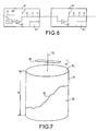
- FIG. 7 illustrates another possible application of a radar according to the invention. It can in particular be applied advantageously to determine the amount of material 70 contained in a tank 71 when the material is not liquid and that its upper surface 72 is not flat.
- the radar 80 comprises a shaft 73 around which it rotates, the antennas facing the material 70. If the vessel is circular, the shaft is for example merged with the axis of symmetry of the vessel. A rotational movement is applied to the radar 80 through the shaft.
- the radar according to the invention can thus map the contents of the tank in three dimensions. It can therefore determine the amount of material 70, knowing the total height H of the tank and the distance from each point of the surface 72 to a relative reference altitude 74, the latter being for example the top of the tank.
Abstract
Description
La présente invention concerne un radar à bas coût, notamment à imagerie à haute résolution. Elle s'applique en particulier pour des radars de surveillance à courte distance telle que par exemple la surveillance de passage à niveau de carrefours ou de parking.The present invention relates to a low-cost radar, especially high-resolution imaging. It applies in particular for short-range surveillance radars such as, for example, crossroads or parking level crossing surveillance.
Il existe encore sur le réseau routier de nombreux passages à niveau, manuels ou automatiques. On dénombre malheureusement des accidents qui se produisent régulièrement. Pour diminuer le risque d'accidents, il peut être intéressant de disposer de moyens de surveillance des passages à niveau, ces moyens transmettant par ailleurs aux trains à l'approche l'état de circulation aux abord des passages à niveau. Ces moyens de surveillance doivent notamment être opérationnels par tous temps, de nuit comme de jour. Un radar à imagerie répond à ces contraintes.There are still many road crossings, manual or automatic, on the road network. There are unfortunately accidents that occur regularly. To reduce the risk of accidents, it may be advantageous to have means of monitoring the level crossings, these means also transmitting trains to approach the state of circulation at the first crossing level. These means of surveillance must especially be operational in all weather, night and day. An imaging radar responds to these constraints.
Il existe plusieurs types de radars à imagerie, en particulier ces radars peuvent être du type :
- radars à balayage mécanique ;
- radars à balayage électronique ;
- radars à formation de faisceaux par le calcul (FFC).
- mechanical scanning radars;
- electronic scanning radars;
- computed beamforming radars (FFC).
Les radars à balayage mécanique ne permettent pas d'obtenir une vision instantanée de la scène observée. Ils sont par ailleurs coûteux en raison de la présence des éléments mécaniques nécessaires pour mouvoir l'antenne. Enfin, ils sont moyennement fiables à cause notamment de l'usure de ces éléments mécaniques.Mechanical scanning radars do not provide an instantaneous view of the observed scene. They are also expensive because of the presence of the mechanical elements necessary to move the antenna. Finally, they are moderately reliable because of the wear of these mechanical elements.
Les radars à balayage électronique permettent quant à eux d'obtenir une vision quasi simultanée de la scène observée. Cependant, ils mettent en oeuvre des circuits électroniques complexes et nécessitent des contraintes de fabrication très fortes, liées au contrôle de la phase et de l'amplitude sur chaque élément rayonnant de l'antenne, ce qui les rend coûteux et limite leur domaine d'application.The electronic scanning radars make it possible to obtain an almost simultaneous vision of the observed scene. However, they implement complex electronic circuits and require very strong manufacturing constraints, related to the control of the phase and the amplitude on each radiating element of the antenna, which makes them expensive and limits their field of action. application.
Les radars à formation de faisceaux par le calcul permettent d'obtenir une vision instantanée de la scène observée. Le contrôle de la phase et de l'amplitude sur chaque élément de l'antenne de réception est effectuée directement par l'algorithme de formation de faisceau par le calcul et les dispersions de l'antenne et des voies analogiques de réception peuvent être compensées par ce traitement. Cependant, ces radars utilisent une réception hétérodyne. De ce fait, chaque élément de l'antenne de réception est suivi d'une chaîne de réception complexe comportant notamment des moyens de mélange, d'amplification, de filtrage et de codage. Le coût de ce type de radar est donc élevé.Computational radars provide an instantaneous view of the observed scene. The control of the phase and amplitude on each element of the receiving antenna is performed directly by the beamforming algorithm by calculation and antenna dispersions and analogue reception channels can be compensated by this processing. However, these radars use heterodyne reception. As a result, each element of the receiving antenna is followed by a complex reception chain comprising, in particular, mixing, amplification, filtering and coding means. The cost of this type of radar is therefore high.
Une demande de brevet
Un but de l'invention est de permettre la réalisation d'un radar à imagerie économique du type à formation de faisceaux par le calcul.An object of the invention is to allow the realization of an economic imaging radar of the beam-forming type by calculation.
A cet effet, l'invention a pour objet un radar qui comporte des moyens de formation de faisceaux par le calcul associés à N voies de réception homodyne, chaque voie fournissant un signal de réception aux moyens de formation de faisceaux par le calcul, l'antenne d'émission étant disposée de telle sorte que sa distance augmente d'une antenne de réception à la suivante. L'espacement entre les antennes est défini de façon à orienter la fuite homodyne dans une direction située dans une zone angulaire de l'espace qui n'est pas traitée par le radar.For this purpose, the object of the invention is a radar which comprises means for beamforming by the calculation associated with N homodyne reception channels, each channel providing a reception signal to the beam forming means by the computation, the transmitting antenna being arranged such that its distance increases from one receiving antenna to the next. The spacing between the antennas is defined to direct homodyne leakage in a direction located in an angular area of space that is not handled by the radar.
La distance de l'antenne d'émission augmente par exemple régulièrement d'une antenne de réception à la suivante. En particulier, les antennes des voies de réception sont par exemple alignées avec un espace d sensiblement constant entre deux antennes consécutives.The distance of the transmitting antenna increases for example regularly from one receiving antenna to the next. In particular, the antennas of the reception channels are for example aligned with a substantially constant space d between two consecutive antennas.
Avantageusement, le radar exploite la fuite homodyne pour réaliser un auto-test de la fonction d'émission-réception.Advantageously, the radar exploits the homodyne leak to perform a self-test of the transmission-reception function.
Dans un mode de réalisation, les antennes de réception sont par exemple réalisées sur un même circuit imprimé.In one embodiment, the receiving antennas are for example made on the same printed circuit.
L'invention a notamment pour principaux avantages qu'elle permet une haute résolution sur une large bande de fréquence, qu'elle s'adapte à de nombreuses applications, qu'elle permet une très bonne reproductibilité de fabrication, qu'elle permet une grande sécurité de fonctionnement, et qu'elle permet un fonctionnement modulaire du radar.The main advantages of the invention are that it allows a high resolution over a wide frequency band, that it adapts to many applications, that it allows a very good reproducibility of manufacture, that it allows a great safety of operation, and that it allows a modular operation of the radar.
D'autres caractéristiques et avantages de l'invention apparaîtront à l'aide de la description qui suit faite en regard de dessins annexés qui représentent :
- la figure 1, par un synoptique, un exemple de réalisation possible d'un radar selon l'invention ;
- la figure 2, une illustration des faisceaux élémentaires d'antennes d'un radar selon l'invention ;
- la figure 3, une illustration de la disposition des antennes élémentaires de réception dans un radar selon l'invention ;
- la figure 4, un exemple de réalisation, en circuit imprimé, des voies de réception d'un radar selon l'invention ;
- la figure 5, une vue détaillée d'une voie de réception dans le mode de réalisation précédent ;
- la figure 6, une illustration de l'aspect modulaire d'un radar selon l'invention ;
- la figure 7, un exemple d'utilisation d'un radar selon l'invention pour déterminer la quantité de matériau dans une cuve.
- FIG. 1, by a block diagram, an exemplary possible embodiment of a radar according to the invention;
- FIG. 2, an illustration of the elementary antenna beams of a radar according to the invention;
- FIG. 3, an illustration of the arrangement of the elementary reception antennas in a radar according to the invention;
- FIG. 4, an exemplary embodiment, in a printed circuit, of reception channels of a radar according to the invention;
- FIG. 5, a detailed view of a reception channel in the preceding embodiment;
- FIG. 6, an illustration of the modular aspect of a radar according to the invention;
- Figure 7, an example of use of a radar according to the invention to determine the amount of material in a tank.
La figure 1 présente par un synoptique un mode de réalisation possible d'un radar selon l'invention, ayant par exemple une fonction d'imagerie. Il s'agit d'un radar à formation de faisceau par le calcul ayant une réception homodyne. La chaîne de réception se résume alors à une démodulation du signal reçu par chaque antenne élémentaire par l'oscillateur local d'émission, du filtrage, de l'amplification et du codage. La réception se faisant en bande de base, il est alors possible d'utiliser des composants de très grande diffusion et de faible coût pour la chaîne de réception. Une telle réception peut néanmoins présenter un inconvénient dissuasif pour une utilisation de surveillance par imagerie radar, il s'agit de la dégradation de la sensibilité du radar due aux fuites homodynes. Cette perte de sensibilité est notamment présente à courte distance, ce qui correspond au cas d'utilisation du radar pour une surveillance de proximité telle que par exemple une surveillance de passage à niveau ou de carrefour. Comme le montrera la description qui suit, l'invention surmonte l'inconvénient précité en réalisant avantageusement une compression des fuites homodynes dans une direction donnée, donc contrôlable.FIG. 1 presents by a block diagram a possible embodiment of a radar according to the invention, having for example an imaging function. It is a computed beamforming radar having a homodyne reception. The reception chain is then reduced to a demodulation of the signal received by each elementary antenna by the local oscillator of transmission, filtering, amplification and coding. The reception being done in baseband, it is then possible to use components of very wide diffusion and low cost for the reception chain. Such reception may nevertheless have a deterrent disadvantage for radar surveillance use, it is the degradation of the sensitivity of the radar due to homodynes leakage. This loss of sensitivity is particularly present at a short distance, which corresponds to the case of use of the radar for proximity monitoring such as, for example, level crossing or intersection surveillance. As will be shown in the following description, the invention overcomes the aforementioned disadvantage by advantageously providing a homodyne leak compression in a given direction, thus controllable.
Ainsi donc un radar selon l'invention tel que représenté par la figure 1 comporte plusieurs voies de réception en parallèle pour une formation de faisceau par le calcul. Par la suite, à titre d'exemple, on considérera que le radar comporte 32 voies de réception. Une voie de réception comporte une antenne élémentaire de réception 1, un mélangeur hyperfréquence 2, un amplificateur 3 et un convertisseur analogique-numérique 4. Plus particulièrement, une antenne élémentaire 1 est reliée à une première entrée d'un mélangeur 2. La deuxième entrée de celui-ci reçoit le signal produit par l'oscillateur local d'émission 5. Etant donné que le radar est du type homodyne, il n'y a pas de transposition de fréquence à une fréquence intermédiaire. La sortie du mélangeur, comportant ainsi le signal de réception démodulé par le signal d'oscillateur local, est reliée à l'entrée d'un amplificateur 3 dont la sortie est reliée à l'entrée d'un convertisseur 4. Ce dernier convertit le signal analogique de réception en un signal numérique destiné notamment à être traité par les moyens de calcul pour la formation de faisceau par le calcul, appelée FFC par la suite. Les 32 signaux numériques issus des 32 voies de réception sont par exemple traités par des moyens 6 de sérialisation des données. En d'autres termes, les 32 signaux parallèles sont par exemple mis en série pour être transmis aux moyens 7 de formation de faisceaux par le calcul, FFC. Ces moyens sont réalisés de façon connue à base de processeurs de traitement du signal. Ces moyens sont par ailleurs associés, par exemple sur les mêmes circuits matériels aux moyens de calcul de transformée de Fourier rapide, FFT, ainsi qu'à d'autres moyens de traitement radar connus par ailleurs. Ces derniers fournissent par exemple par ailleurs la commande numérique de forme d'onde radar transmise à l'oscillateur local 5 par l'intermédiaire d'une boucle à verrouillage de phase 8, appelée encore PLL selon les initiales de l'expression anglo-saxonne « Phase Loop Lock ». La forme d'onde produite 9 est par exemple celle d'un radar FMCW, c'est-à-dire une forme d'onde continue dont la fréquence est modulée linéairement par des rampes montantes ou descendantes. D'autres formes d'ondes sont possibles, par exemple du type à saut de fréquence. Les moyens de traitement radar 7 sont par exemple reliés à une interface homme machine 10, destinée notamment à exploiter l'image radar.Thus, a radar according to the invention as represented by FIG. 1 comprises several reception channels in parallel for beamforming by calculation. Subsequently, as an example, consider that the radar has 32 reception channels. A reception channel comprises an
A l'émission, la sortie de l'oscillateur local est reliée à une antenne d'émission 11. Cet oscillateur local présente en sortie un signal suffisamment puissant pour l'émission, mais aussi pour alimenter les 32 mélangeurs 2. Avantageusement, l'antenne d'émission est mise à l'écart des antennes de réception pour ne pas perturber la réception.On transmission, the output of the local oscillator is connected to a transmitting antenna 11. This local oscillator has as output a signal powerful enough for the transmission, but also for supplying the 32
Chaque antenne 1, 11 de réception et d'émission, est par exemple constituée de deux pastilles, encore appelées patches dans la littérature anglo-saxonne. Les antennes de réception 1 sont par exemple réalisées sur un même circuit imprimé 12. De préférence, les circuits mélangeurs 2 sont eux aussi réalisés sur ce même circuit imprimé. Moyennant quelques précautions, l'antenne d'émission peut elle aussi être réalisée sur ce circuit imprimé.Each
La figure 2 illustre la résolution obtenue par FFC ainsi que le domaine angulaire de réception, dans le cas d'utilisation de 32 voies de réception. La FFC permet le calcul de 32 faisceaux élémentaires 21 qui se chevauchent. La largeur angulaire occupée par ces 32 faisceaux élémentaires est par exemple de l'ordre de 60°, correspondant à l'angle d'action du radar. La résolution correspond à la largeur d'un faisceau élémentaire diminuée de ses zones de chevauchement, ce qui correspond par exemple à un angle de l'ordre 3,5°, caractérisant la résolution du radar. Un radar à FFC permet donc d'obtenir une haute résolution, sur un large domaine angulaire pourvu que l'on prévoie suffisamment de voies de réception.FIG. 2 illustrates the resolution obtained by FFC as well as the reception angular domain, in the case of use of 32 reception channels. The FFC allows the calculation of 32 overlapping
La technique de réception homodyne est par ailleurs économique, puisqu'elle évite une certaine complexité de circuits et permet d'utiliser des composants de grande diffusion et donc de faible coût pour la chaîne de réception. Les coûts sont encore diminués en réalisant une partie des circuits de réception, notamment les antennes élémentaires 1 et les circuits mélangeurs 2 par la technique du circuit imprimé. Les zones conductrices constituant les antennes 1, les mélangeurs 2 et les lignes hyperfréquence peuvent en effet être obtenus par usinage chimique sur un support organique selon la technique classique du circuit imprimé qui est bien éprouvée et peu coûteuse. Outre l'aspect économique, il en résulte par ailleurs une très bonne reproductibilité des pièces et une grande fiabilité de fonctionnement. Enfin, la réduction des coûts peut aussi être poursuivie en imprimant tous les éléments, c'est-à-dire les antennes, les mélangeurs et les lignes hyperfréquence, sur une même face du support. Cela évite par ailleurs la réalisation d'un grand nombre de traversées destinées aux signaux hyperfréquence sur le circuit imprimé. Ces traversées sont ainsi réduites au seul passage du signal fourni par l'oscillateur local 5 et éventuellement aux signaux d'émission si l'antenne d'émission est aussi présente sur le circuit imprimé.The homodyne reception technique is also economical, since it avoids a certain complexity of circuits and makes it possible to use components of large diffusion and therefore of low cost for the reception chain. The costs are further reduced by realizing part of the reception circuits, in particular the
L'invention permet donc d'obtenir un radar à imagerie haute résolution économique. Avantageusement, l'invention permet de maîtriser les fuites homodynes, perturbatrices de réception.The invention thus makes it possible to obtain an economical high resolution imaging radar. Advantageously, the invention makes it possible to control homodyne leaks, which are disturbing to reception.
La figure 3 illustre une disposition des antennes de réception qui permet de rejeter ces fuites dans une direction donnée, et donc d'en assurer le contrôle. Les antennes de réception, notées AR1, AR2, ...ARi, ARi+1, ...ARN, sont alignées régulièrement, c'est-à-dire avec un espace d sensiblement constant entre deux antennes consécutives d'antennes. L'antenne d'émission AE est par exemple alignée avec les antennes de réception sans y être mélangée. Elle est au moins disposée de telle sorte que sa distance augmente régulièrement d'une antenne de réception à l'autre, c'est-à-dire que sa distance augmente par exemple selon un pas constant. Dans l'exemple de la figure 3, l'antenne de réception est à une distance D quelconque d'une première antenne AR1, puis à une distance D+d d'une deuxième antenne AR2, puis à une distance D+2d d'une troisième antenne de réception et ainsi de suite.FIG. 3 illustrates an arrangement of receiving antennas which makes it possible to reject these leaks in a given direction, and thus to control them. The reception antennas, denoted AR 1 , AR 2 ,... AR i , AR i + 1 , ... AR N , are aligned regularly, that is to say with a substantially constant space d between two consecutive antennas antennas. The transmitting antenna AE is for example aligned with the receiving antennas without being mixed. It is at least arranged so that its distance increases regularly from one receiving antenna to another, that is to say that its distance increases for example in a constant pitch. In the example of FIG. 3, the receiving antenna is at any distance D of a first antenna AR 1 , then at a distance D + d of a second antenna AR 2 , then at a distance D + 2d a third receiving antenna and so on.
L'antenne d'émission AE rayonne un signal hyperfréquence s(t) accompagné d'un bruit à bande limitée représentant la fuite homodyne, vers les antennes de réception par couplage. Le couplage se produit dans l'air mais aussi entre les lignes hyperfréquence d'émission et de réception. La réception étant du type homodyne et non hétérodyne, il n'y a pas de transposition de fréquence permettant de s'affranchir de ce bruit rayonné.The transmitting antenna AE radiates a microwave signal s (t) accompanied by a limited band noise representing the homodyne leak, to the reception antennas by coupling. The coupling occurs in the air but also between the microwave transmission and reception lines. The reception being of the homodyne and non-heterodyne type, there is no frequency transposition making it possible to overcome this radiated noise.
La fuite homodyne s(t) rayonnée par l'antenne se retrouve donc au niveau de la première antenne avec un retard T = 2D/c dû à la distance D, c étant la vitesse de la lumière. La première antenne de réception AR1 reçoit donc la fuite s(t-T). Entre la deuxième antenne de réception AR2 et la première antenne AR1, s'ajoute un retard τ = 2d/c. Ce même retard s'ajoute par la suite d'une antenne à sa suivante. Ainsi, à un instant t, la fuite rayonnée vers chaque antenne est définie comme suit :
- Antenne AR1 s(t - T)
- Antenne AR2 s(t - T - τ)
- Antenne ARi s(t - T - 2τ)
- Antenne ARi+1 s(t - T - iτ)
- Antenne ARN s(t - T - (N-1)τ)
- Antenna AR 1 s (t - T)
- Antenna AR 2 s (t - T - τ)
- Antenna AR i s (t - T - 2τ)
- Antenna AR i + 1 s (t - T - iτ)
- Antenna AR N s (t - T - (N-1) τ)
La fuite homodyne captée est donc la même pour toutes les antennes, au retard τ près, qui est constant d'une antenne à la suivante. Il en résulte que la fuite homodyne est captée par les antennes selon une direction apparente 31 qui est parfaitement définie en fonction des retards τ. On peut donc choisir l'espacement entre les antennes de façon à orienter la fuite homodyne dans une direction apparente donnée. Cette direction apparente dépend de la direction réelle d'arrivée de la fuite et du diagramme d'ambiguïté du réseau. Par exemple, pour une antenne dont la source d'émission et les sources ou antennes de réception sont alignées, la direction d'arrivée de la fuite est proche de 90°. Cette fuite n'est pas vue directement. Elle est vue à travers le diagramme d'ambiguïté du réseau dans une direction définie par un angle θ vérifiant sinθ = (λ/d - 1). Ainsi par exemple, pour d=0,7λ, il vient θ = 25°. L'espacement entre les antennes de réception peut être choisi de façon à orienter la fuite homodyne dans une direction choisie.The captured homodyne leak is therefore the same for all the antennas, with the delay τ near, which is constant from one antenna to the next. As a result, the homodyne leak is picked up by the antennas in an
Le bruit qui accompagne la fuite est généralement à bande étroite et subit par conséquent le même traitement, ce qui revient à le concentrer dans une direction particulière qui, de préférence, ne sera pas exploitée par le radar en mode opérationnel. Il peut par contre être exploité pour réaliser un auto-test de la fonction émission-réception, sans adjonction de circuits complémentaires, les adaptations étant uniquement logicielles. Un radar selon l'invention peut donc, économiquement et simplement, exploiter la fuite pour réaliser un auto-test des fonctions d'émission et de réception.The noise that accompanies the leak is generally narrowband and therefore undergoes the same processing, which amounts to concentrating it in a particular direction which, preferably, will not be exploited by the radar in operational mode. It can however be used to perform a self-test of the transmission-reception function, without the addition of complementary circuits, the adaptations being only software. A radar according to the invention can therefore economically and simply exploit the leak to perform a self-test of the transmission and reception functions.
La figure 4 illustre un mode de réalisation possible des antennes de réception et des mélangeurs. Ce mode de réalisation comporte toujours à titre d'exemple 32 voies. Les antennes et les lignes hyperfréquence sont imprimées sur un support 12, par exemple organique du type époxy. De préférence, tous ces éléments sont imprimés sur la même face du support, l'autre face étant recouverte d'un plan de masse. Les antennes sont alignées selon une distance sensiblement constante d'une antenne à la suivante. Chaque antenne de réception élémentaire comporte par exemple deux pastilles 41, 42 reliées en parallèle à une ligne hyperfréquence 43. Cette dernière relie les antennes à son circuit mélangeur 2. Avantageusement, un écran électromagnétique protège ces derniers des rayonnements extérieurs. A cet effet une bande métallique 44 entoure les circuits mélangeurs. Cette bande métallique est coupée aux endroits où passent les lignes de liaison hyperfréquence 43 vers les antennes. Un capot métallique non représenté vient ensuite recouvrir les mélangeurs, les bords du capot étant placés au contact de la bande métallique 44. Des trous 45, taraudés ou non, sont par exemple prévus pour permettre la fixation du capot sur le support 12. L'espace intérieur entre le capot et le circuit imprimé est par exemple rempli par de la mousse absorbante pour éviter notamment un couplage électromagnétique entre les différentes lignes hyperfréquence.Figure 4 illustrates a possible embodiment of receiving antennas and mixers. This embodiment still includes 32 channels as an example. Antennas and microwave lines are printed on a
Le signal d'oscillateur local est fourni aux mélangeurs par une ligne hyperfréquence imprimée 46, laquelle se subdivise en branches successives, chaque branche se divisant par exemple en deux, de sorte que la longueur de ligne hyperfréquence entre l'oscillateur local et un mélangeur soit la même pour tous les mélangeurs, dans le but notamment que les signaux de démodulation présents sur les mélangeurs soient tous synchrones. Un trou 47 permet par exemple de faire passer un câble transportant le signal hyperfréquence produit par l'oscillateur local, l'âme du câble étant par exemple soudée sur la ligne hyperfréquence 46 imprimée sur le support 12.The local oscillator signal is supplied to the mixers by a printed
La figure 5 illustre par une vue agrandie un mode de réalisation des mélangeurs 2, dont une entrée reçoit le signal capté par l'antenne élémentaire associée et l'autre entrée reçoit le signal de démodulation fourni par l'oscillateur local 5. La sortie du mélangeur attaque l'entrée de l'amplificateur 3 de la voie de réception.FIG. 5 illustrates, by an enlarged view, an embodiment of the
Une antenne élémentaire d'une voie de réception comporte par exemple deux pastilles 41, 42. Le signal capté par cette antenne élémentaire transite par une liaison hyperfréquence 43 vers le mélangeur 2. Le mélangeur utilisé est par exemple un mélangeur équilibré qui comporte deux diodes, non représentées, montées en tête bêche en sortie d'un anneau hybride large bande 0/180° 51. Trois lignes quart d'onde 52, 53, 54 servent par exemple de retour de masse aux diodes. La longueur d'onde considérée est la longueur d'onde à la fréquence centrale. Une première ligne quart d'onde 52 sépare un premier point de masse, représenté par un trou métallisé 55, de la cathode de la première diode. Une deuxième ligne quart d'onde 53 sépare l'anode de la première diode de la cathode de la deuxième diode. Une troisième ligne quart d'onde sépare la cathode de la deuxième diode d'un point de masse, représenté par un trou métallisé 56. Les deux diodes sont connectées par ailleurs sur la ligne 43 reliant les pastilles 41, 42 au mélangeur et véhiculant le signal détecté. Des éléments de filtrage 57, 58 isolent le signal détecté du signal de sortie du mélangeur. La sortie du mélangeur est matérialisée par un point de connexion 59 relié à l'entrée du mélangeur 3.An elementary antenna of a reception channel comprises, for example, two
Le circuit imprimé 12 sur lequel sont réalisées les antennes élémentaires 1 et les lignes hyperfréquence peut être fixé sur une face d'une platine. Sur l'autre face de la platine peuvent être disposés notamment les amplificateurs (3), les convertisseurs analogique-numérique 4, les moyens de mise en série 6, les moyens de traitement radar 7, la boucle à verrouillage de phase 8 ainsi que l'oscillateur local 5. Ces moyens sont supportés par des circuits imprimés qui sont par exemple eux-mêmes fixés sur la platine. La platine équipée des ces différents circuits peut être protégée par une enveloppe munie d'une fenêtre hyperfréquence en regard des antennes AE, 1. A titre d'exemple, le radar ainsi obtenu peut présenter une hauteur de l'ordre de 20 cm, une profondeur de 10 cm et une largeur de 80 cm, pour un poids d'environ 8 kg.The printed
La figure 6 illustre, par un synoptique, un autre avantage d'un radar selon l'invention. Il s'agit de sa modularité. Plusieurs radars selon l'invention peuvent en effet être câblés en parallèle dans le but d'obtenir un radar de plus grande résolution ou de plus grand domaine angulaire d'action. Un radar tel que décrit selon les figures précédentes représente donc un module 61. Un premier module joue le rôle de module pilote. En particulier son oscillateur local 5 commande aussi tous les autres modules. A cet effet, chaque module comporte en entrée un amplificateur 62 pour permettre au signal produit par l'oscillateur du premier module de commander tous les autres modules. Le radar constitué de tous les modules ne comporte par ailleurs qu'une antenne d'émission AE active, qui est par exemple celle du premier module, cette antenne étant alimentée par l'oscillateur local de ce premier module. Les antennes d'émission et les oscillateurs locaux des autres modules peuvent donc rester inactifs. Pour des raisons d'efficacité industrielle, tous les modules sont par exemples identiques. Ainsi, la sortie du circuit d'amplification 62 du signal d'oscillateur local qui alimente les circuits de réception du premier module, attaque par ailleurs l'entrée du circuit d'amplification 62 du deuxième module et ainsi de suite. Les circuits de traitement radar 6, 7, notamment les circuits de FFC fonctionnent en parallèle. Le domaine angulaire de surveillance ou la résolution angulaire peuvent ainsi être augmentés par le nombre accru d'antennes et de voies de réceptions en parallèle.FIG. 6 illustrates, by a synoptic, another advantage of a radar according to the invention. It's about its modularity. Several radars according to the invention can in fact be wired in parallel in order to obtain a radar of greater resolution or greater angular range of action. A radar as described according to the preceding figures therefore represents a
Il est à noter qu'un radar selon l'invention permet une vision instantanée de la scène observée. Par ailleurs, il est en particulier aisé de former des diagrammes d'antenne très différents avec le même matériel. Un radar selon l'invention est donc adaptable à de nombreuses situations. Il n'est pas nécessaire de réaliser un autofocus, c'est-à-dire un réglage de phases entre les différentes voies de réception, un simple réglage de gain suffit. Enfin, le radar possède une capacité large bande avec une haute résolution.It should be noted that a radar according to the invention allows an instantaneous view of the observed scene. Moreover, it is particularly easy to form very different antenna patterns with the same material. A radar according to the invention is therefore adaptable to many situations. It is not necessary to perform an autofocus, that is to say a phase adjustment between the different reception channels, a simple gain adjustment is sufficient. Finally, the radar has a broadband capability with high resolution.
Un radar selon l'invention peut être utilisé pour de nombreuses applications. Il peut être utilisé notamment pour des applications de surveillance, telles que par exemple de la gestion de trafic, la surveillance de carrefours, la surveillance de parkings, la surveillance de passages à niveau, la surveillance de voies de péages et plus généralement pour tous types de surveillance et de protection de zones.A radar according to the invention can be used for many applications. It can be used in particular for surveillance applications, such as, for example, traffic management, surveillance of junctions, surveillance of car parks, monitoring of level crossings, monitoring of toll roads and more generally for all types. surveillance and protection of areas.
Un radar selon l'invention peut aussi être utilisé pour une détection d'obstacle avec une grande précision. Un radar selon l'invention peut ainsi équiper un robot mais aussi un véhicule de secours évoluant dans de la fumée. L'aspect modulaire du radar permet notamment son adaptation à plusieurs types d'application en fonction de l'angle de surveillance nécessaire.A radar according to the invention can also be used for obstacle detection with high accuracy. A radar according to the invention can thus equip a robot but also a rescue vehicle evolving in smoke. The modular aspect of the radar makes it possible to adapt it to several types of application depending on the required surveillance angle.
La figure 7 illustre une autre application possible d'un radar selon l'invention. Il peut notamment s'appliquer avantageusement pour déterminer la quantité de matériau 70 contenu dans une cuve 71 lorsque ce matériau n'est pas liquide et que sa surface supérieure 72 n'est pas plane. Le radar 80 comporte un arbre 73 autour duquel il tourne, les antennes étant en regard du matériau 70. Si la cuve est circulaire, l'arbre est par exemple confondu avec l'axe de symétrie de la cuve. Un mouvement de rotation est appliqué au radar 80 par l'intermédiaire de l'arbre. Le radar selon l'invention peut ainsi réaliser une cartographie en trois dimensions du contenu de la cuve. Il peut donc déterminer la quantité de matériau 70, en connaissant la hauteur totale H de la cuve et la distance de chaque point de la surface 72 à une altitude de référence relative 74, cette dernière étant par exemple le dessus de la cuve.Figure 7 illustrates another possible application of a radar according to the invention. It can in particular be applied advantageously to determine the amount of
Les exemples d'applications cités précédemment ne sont bien sûr pas limitatifs.The examples of applications mentioned above are of course not limiting.
Claims (19)
- Radar, comprising means for beam-formation by computation (7) associated with N homodyne reception channels, each channel supplying a reception signal to the means for beam-formation by computation, the transmission antenna (AE) being arranged so that its distance increases from one reception antenna (1) to the next, characterized in that the spacing between the antennas being defined so as to orient the homodyne leakage in a direction located in an angular zone of space that is not processed by the radar, the distance of the transmission antenna (AE) increases regularly from one reception antenna (1) to the next.
- Radar according to Claim 1, characterized in that the reception channel antennas (1) are aligned with a substantially constant space between two consecutive antennas.
- Radar according to either of the preceding claims, characterized in that the transmission antenna (AE) is aligned with the reception antennas (1).
- Radar according to any one of the preceding claims, characterized in that it uses the homodyne leakage to perform a self-test of the transmission-reception function.
- Radar according to any one of the preceding claims, characterized in that a reception channel comprises an antenna (1), a microwave mixer (2), an amplifier (3) and an analogue-digital converter (4), an antenna (1) is linked to a first input of the mixer (2), the second input of said mixer receiving the signal produced by a transmission local oscillator (5), the output of the mixer being linked to the input of the amplifier (3), the output of which is linked to the input of the converter (4), said converter converting the analogue reception signal into a digital signal designed to be processed by the means for beam-formation by computation.
- Radar according to Claim 5, characterized in that the reception antennas (1) are of the patch type made on one and the same printed circuit (12).
- Radar according to Claim 6, characterized in that the mixers (2) are made on this same printed circuit.
- Radar according to either of Claims 5 or 6, characterized in that a metal band (44) surrounds the mixers, this band being cut at places where the microwave links pass towards the antennas, a metal cover covering the mixers with its edges in contact with the metal band.
- Radar according to any one of the preceding claims, characterized in that the waveform is of the FMCW type, a continuous waveform whose frequency is modulated in ramps.
- Radar according to any one of Claims 1 to 8, characterized in that its waveform is of the frequency-hopping type.
- Radar according to any one of the preceding claims, characterized in that it comprises a local oscillator (5) powering the transmission antenna (AE) and the reception channels.
- Radar according to Claim 12, characterized in that the microwave line length between the local oscillator (5) and a mixer (2) is the same for all the mixers.
- Radar according to any one of Claims 5 to 12, characterized in that the printed circuit (12) being fixed to a face of a plate, the other face of this plate supports the radar processing means.
- Modular radar, characterized in that a module (61) is a radar according to any one of the preceding claims, the circuits for beam-formation by computation operating in parallel.
- Radar according to Claim 14, characterized in that a first module functions as a driver module, its local oscillator (5) controlling all the other modules, each module including an amplifier (62) at an input to amplify the signal from the local oscillator (5).
- Radar according to either of Claims 14 or 15, characterized in that the output of the amplification circuit (62) for the local oscillator signal which feeds the reception circuits of the driver module, also drives the input of the amplification circuit (62) of the second module, and so on.
- Radar according to any one of Claims 14 to 16, characterized in that its transmission antenna (AE) is that of the driver module, fed by the local oscillator of the driver module.
- Radar according to any one of the preceding claims, characterized in that it comprises a shaft (73) around which it rotates to sweep the interior space of a container containing a material, the antennas (1, AE) being located facing this material.
- Radar according to any one of the preceding claims, characterized in that it includes an imaging function.
Applications Claiming Priority (2)
| Application Number | Priority Date | Filing Date | Title |
|---|---|---|---|
| FR0004983 | 2000-04-18 | ||
| FR0004983A FR2807841B1 (en) | 2000-04-18 | 2000-04-18 | HIGH RESOLUTION LOW COST IMAGING RADAR |
Publications (2)
| Publication Number | Publication Date |
|---|---|
| EP1152258A1 EP1152258A1 (en) | 2001-11-07 |
| EP1152258B1 true EP1152258B1 (en) | 2007-09-12 |
Family
ID=8849373
Family Applications (1)
| Application Number | Title | Priority Date | Filing Date |
|---|---|---|---|
| EP01400949A Expired - Lifetime EP1152258B1 (en) | 2000-04-18 | 2001-04-12 | Low-cost radar, in particular for high-resolution imaging |
Country Status (6)
| Country | Link |
|---|---|
| US (1) | US6429805B1 (en) |
| EP (1) | EP1152258B1 (en) |
| JP (1) | JP2001356166A (en) |
| AT (1) | ATE373245T1 (en) |
| DE (1) | DE60130396T2 (en) |
| FR (1) | FR2807841B1 (en) |
Families Citing this family (7)
| Publication number | Priority date | Publication date | Assignee | Title |
|---|---|---|---|---|
| US7330032B2 (en) * | 2003-12-30 | 2008-02-12 | The Mitre Corporation | Techniques for building-scale electrostatic tomography |
| FR2882855B1 (en) * | 2005-03-01 | 2007-05-18 | Thales Sa | ACTIVE MODULE INTEGRATED WITH AN ELECTRONIC SCANNING ANTENNA AND RADAR COMPRISING SUCH ANTENNA, PARTICULARLY APPLIED TO METEOROLOGY |
| IL178221A0 (en) * | 2006-09-20 | 2008-01-20 | Elta Systems Ltd | Active protection method and system |
| GB201302809D0 (en) * | 2013-02-18 | 2013-04-03 | Roke Manor Research | An object detector |
| DE102013104147A1 (en) * | 2013-04-24 | 2014-10-30 | Hella Kgaa Hueck & Co. | Radar device, in particular for a motor vehicle |
| CN111007491A (en) * | 2019-12-30 | 2020-04-14 | 西安电子科技大学 | Non-uniform array synthesis method based on error matrix guidance |
| CN115015898A (en) * | 2021-03-04 | 2022-09-06 | 智能雷达系统有限公司 | Radar apparatus for detecting target object |
Family Cites Families (12)
| Publication number | Priority date | Publication date | Assignee | Title |
|---|---|---|---|---|
| FR2690755B1 (en) | 1992-04-30 | 1994-08-26 | Thomson Csf | Method and system for detecting one or more objects in an angular zone, and applications. |
| FR2692681B1 (en) | 1992-06-19 | 1994-09-02 | Thomson Csf | Method for discriminating obstacles from a radar, and applications. |
| US5351053A (en) * | 1993-07-30 | 1994-09-27 | The United States Of America As Represented By The Secretary Of The Air Force | Ultra wideband radar signal processor for electronically scanned arrays |
| FR2718249B1 (en) | 1994-04-05 | 1996-04-26 | Thomson Csf | Radar distance measuring method and device. |
| JP3663702B2 (en) * | 1995-12-05 | 2005-06-22 | 株式会社デンソー | Planar array antenna and phase monopulse radar apparatus |
| JPH1093322A (en) * | 1996-09-18 | 1998-04-10 | Honda Motor Co Ltd | Antenna system |
| FR2757639B1 (en) | 1996-12-20 | 1999-03-26 | Thomson Csf | RADAR FOR DETECTING OBSTACLES IN PARTICULAR FOR MOTOR VEHICLES |
| FR2761480B1 (en) | 1997-03-28 | 1999-06-11 | Thomson Csf | METHOD AND DEVICE FOR REMOTE AMBIGUITY REMOTE APPLIED IN PARTICULAR TO A CONTINUOUS WAVE AND FREQUENCY JUMP RADAR |
| US6008760A (en) * | 1997-05-23 | 1999-12-28 | Genghis Comm | Cancellation system for frequency reuse in microwave communications |
| US5959570A (en) * | 1997-11-21 | 1999-09-28 | Raytheon Company | Automotive forward looking sensor blockage detection system and related techniques |
| JP3525426B2 (en) * | 1997-11-28 | 2004-05-10 | トヨタ自動車株式会社 | Radar equipment |
| US6297764B1 (en) * | 1999-12-13 | 2001-10-02 | Harris Corporation | Radar receiver having matched filter processing |
-
2000
- 2000-04-18 FR FR0004983A patent/FR2807841B1/en not_active Expired - Fee Related
-
2001
- 2001-04-11 JP JP2001112728A patent/JP2001356166A/en not_active Withdrawn
- 2001-04-12 EP EP01400949A patent/EP1152258B1/en not_active Expired - Lifetime
- 2001-04-12 AT AT01400949T patent/ATE373245T1/en not_active IP Right Cessation
- 2001-04-12 DE DE60130396T patent/DE60130396T2/en not_active Expired - Lifetime
- 2001-04-18 US US09/836,360 patent/US6429805B1/en not_active Expired - Fee Related
Also Published As
| Publication number | Publication date |
|---|---|
| FR2807841A1 (en) | 2001-10-19 |
| FR2807841B1 (en) | 2003-10-03 |
| EP1152258A1 (en) | 2001-11-07 |
| US6429805B1 (en) | 2002-08-06 |
| ATE373245T1 (en) | 2007-09-15 |
| JP2001356166A (en) | 2001-12-26 |
| DE60130396T2 (en) | 2008-06-12 |
| DE60130396D1 (en) | 2007-10-25 |
Similar Documents
| Publication | Publication Date | Title |
|---|---|---|
| EP2532050B1 (en) | On-board directional flat-plate antenna, vehicle comprising such an antenna, and satellite telecommunication system comprising such a vehicle | |
| EP2532046B1 (en) | Flat-plate scanning antenna for land mobile application, vehicle comprising such an antenna, and satellite telecommunication system comprising such a vehicle | |
| EP2296007B1 (en) | Radar with beam agility, in particular for the function of detecting and avoiding obstacles | |
| EP2831615B1 (en) | Device for active and passive electromagnetic detection with a low likelihood of interception | |
| EP3315994A1 (en) | Multibeam fmcw radar, in particular for a motor vehicle | |
| EP0457880B1 (en) | Airborne iff antenna with switchable multiple diagrams | |
| FR2865041A1 (en) | INTEGRATED CIRCUIT FOR MEASURING DISTANCE AND / OR SPEED OF OBJECTS | |
| EP3329550B1 (en) | Transceiver device and associated antenna | |
| EP1152258B1 (en) | Low-cost radar, in particular for high-resolution imaging | |
| EP3577721A1 (en) | Elementary antenna comprising a planar radiating device | |
| CA1283972C (en) | Adaptive antenne system for radio waves, especially microwaves | |
| EP3321711B1 (en) | Receiving device for electronic scanning antenna capable of operating in radar and resm mode, and radar provided with such a device | |
| EP3859882B1 (en) | Radioelectric system with multiple antenna networks and with adaptive waveforms | |
| EP2341363B1 (en) | System for responding to a signal emitted by a radar and use of said system mainly for testing radars, in particular MTI radars | |
| EP0083534B1 (en) | Mls with interference protection | |
| EP0638821B1 (en) | Microwave imaging radar system with double coverage area, to be installed on board a satellite | |
| EP0919833B1 (en) | Device for detecting concealed objects, especially mines | |
| EP0021862B1 (en) | Device for transmitting radio communication signals in a secondary radar system | |
| EP0928042A1 (en) | Wide band detection means, particularly radars | |
| FR2749707A1 (en) | Wide angular sweep antenna for microwave frequencies | |
| EP1286416A1 (en) | Antenna closing and phase-shifting | |
| WO2003019228A1 (en) | Maritime radar transponder | |
| EP1233282A1 (en) | System with distributed transmit and receive antennas, in particular for radar with synthetic emission and beamforming | |
| FR2734410A1 (en) | Microwave frequency antenna for radar jamming suppression | |
| FR2576692A1 (en) | VOR Doppler radio-navigation system comprising a central stack of radiating elements |
Legal Events
| Date | Code | Title | Description |
|---|---|---|---|
| PUAI | Public reference made under article 153(3) epc to a published international application that has entered the european phase |
Free format text: ORIGINAL CODE: 0009012 |
|
| AK | Designated contracting states |
Kind code of ref document: A1 Designated state(s): AT BE CH CY DE DK ES FI FR GB GR IE IT LI LU MC NL PT SE TR |
|
| AX | Request for extension of the european patent |
Free format text: AL;LT;LV;MK;RO;SI |
|
| 17P | Request for examination filed |
Effective date: 20020429 |
|
| AKX | Designation fees paid |
Free format text: AT BE CH CY DE DK ES FI FR GB GR IE IT LI LU MC NL PT SE TR |
|
| 17Q | First examination report despatched |
Effective date: 20061205 |
|
| GRAP | Despatch of communication of intention to grant a patent |
Free format text: ORIGINAL CODE: EPIDOSNIGR1 |
|
| GRAS | Grant fee paid |
Free format text: ORIGINAL CODE: EPIDOSNIGR3 |
|
| GRAA | (expected) grant |
Free format text: ORIGINAL CODE: 0009210 |
|
| AK | Designated contracting states |
Kind code of ref document: B1 Designated state(s): AT BE CH CY DE DK ES FI FR GB GR IE IT LI LU MC NL PT SE TR |
|
| REG | Reference to a national code |
Ref country code: GB Ref legal event code: FG4D Free format text: NOT ENGLISH |
|
| REG | Reference to a national code |
Ref country code: CH Ref legal event code: EP |
|
| REF | Corresponds to: |
Ref document number: 60130396 Country of ref document: DE Date of ref document: 20071025 Kind code of ref document: P |
|
| REG | Reference to a national code |
Ref country code: IE Ref legal event code: FG4D Free format text: LANGUAGE OF EP DOCUMENT: FRENCH |
|
| GBT | Gb: translation of ep patent filed (gb section 77(6)(a)/1977) |
Effective date: 20071219 |
|
| PG25 | Lapsed in a contracting state [announced via postgrant information from national office to epo] |
Ref country code: FI Free format text: LAPSE BECAUSE OF FAILURE TO SUBMIT A TRANSLATION OF THE DESCRIPTION OR TO PAY THE FEE WITHIN THE PRESCRIBED TIME-LIMIT Effective date: 20070912 |
|
| PG25 | Lapsed in a contracting state [announced via postgrant information from national office to epo] |
Ref country code: AT Free format text: LAPSE BECAUSE OF FAILURE TO SUBMIT A TRANSLATION OF THE DESCRIPTION OR TO PAY THE FEE WITHIN THE PRESCRIBED TIME-LIMIT Effective date: 20070912 |
|
| NLV1 | Nl: lapsed or annulled due to failure to fulfill the requirements of art. 29p and 29m of the patents act | ||
| PG25 | Lapsed in a contracting state [announced via postgrant information from national office to epo] |
Ref country code: NL Free format text: LAPSE BECAUSE OF FAILURE TO SUBMIT A TRANSLATION OF THE DESCRIPTION OR TO PAY THE FEE WITHIN THE PRESCRIBED TIME-LIMIT Effective date: 20070912 Ref country code: GR Free format text: LAPSE BECAUSE OF FAILURE TO SUBMIT A TRANSLATION OF THE DESCRIPTION OR TO PAY THE FEE WITHIN THE PRESCRIBED TIME-LIMIT Effective date: 20071213 Ref country code: ES Free format text: LAPSE BECAUSE OF FAILURE TO SUBMIT A TRANSLATION OF THE DESCRIPTION OR TO PAY THE FEE WITHIN THE PRESCRIBED TIME-LIMIT Effective date: 20071223 |
|
| REG | Reference to a national code |
Ref country code: IE Ref legal event code: FD4D |
|
| PG25 | Lapsed in a contracting state [announced via postgrant information from national office to epo] |
Ref country code: PT Free format text: LAPSE BECAUSE OF FAILURE TO SUBMIT A TRANSLATION OF THE DESCRIPTION OR TO PAY THE FEE WITHIN THE PRESCRIBED TIME-LIMIT Effective date: 20080212 |
|
| PG25 | Lapsed in a contracting state [announced via postgrant information from national office to epo] |
Ref country code: SE Free format text: LAPSE BECAUSE OF FAILURE TO SUBMIT A TRANSLATION OF THE DESCRIPTION OR TO PAY THE FEE WITHIN THE PRESCRIBED TIME-LIMIT Effective date: 20071212 |
|
| PLBE | No opposition filed within time limit |
Free format text: ORIGINAL CODE: 0009261 |
|
| STAA | Information on the status of an ep patent application or granted ep patent |
Free format text: STATUS: NO OPPOSITION FILED WITHIN TIME LIMIT |
|
| PG25 | Lapsed in a contracting state [announced via postgrant information from national office to epo] |
Ref country code: DK Free format text: LAPSE BECAUSE OF FAILURE TO SUBMIT A TRANSLATION OF THE DESCRIPTION OR TO PAY THE FEE WITHIN THE PRESCRIBED TIME-LIMIT Effective date: 20070912 |
|
| 26N | No opposition filed |
Effective date: 20080613 |
|
| BERE | Be: lapsed |
Owner name: THALES Effective date: 20080430 |
|
| PG25 | Lapsed in a contracting state [announced via postgrant information from national office to epo] |
Ref country code: IE Free format text: LAPSE BECAUSE OF FAILURE TO SUBMIT A TRANSLATION OF THE DESCRIPTION OR TO PAY THE FEE WITHIN THE PRESCRIBED TIME-LIMIT Effective date: 20070912 |
|
| PG25 | Lapsed in a contracting state [announced via postgrant information from national office to epo] |
Ref country code: MC Free format text: LAPSE BECAUSE OF NON-PAYMENT OF DUE FEES Effective date: 20080430 |
|
| REG | Reference to a national code |
Ref country code: CH Ref legal event code: PL |
|
| PG25 | Lapsed in a contracting state [announced via postgrant information from national office to epo] |
Ref country code: LI Free format text: LAPSE BECAUSE OF NON-PAYMENT OF DUE FEES Effective date: 20080430 Ref country code: CH Free format text: LAPSE BECAUSE OF NON-PAYMENT OF DUE FEES Effective date: 20080430 |
|
| PG25 | Lapsed in a contracting state [announced via postgrant information from national office to epo] |
Ref country code: BE Free format text: LAPSE BECAUSE OF NON-PAYMENT OF DUE FEES Effective date: 20080430 |
|
| PG25 | Lapsed in a contracting state [announced via postgrant information from national office to epo] |
Ref country code: CY Free format text: LAPSE BECAUSE OF FAILURE TO SUBMIT A TRANSLATION OF THE DESCRIPTION OR TO PAY THE FEE WITHIN THE PRESCRIBED TIME-LIMIT Effective date: 20070912 |
|
| PG25 | Lapsed in a contracting state [announced via postgrant information from national office to epo] |
Ref country code: LU Free format text: LAPSE BECAUSE OF NON-PAYMENT OF DUE FEES Effective date: 20080412 |
|
| PG25 | Lapsed in a contracting state [announced via postgrant information from national office to epo] |
Ref country code: TR Free format text: LAPSE BECAUSE OF FAILURE TO SUBMIT A TRANSLATION OF THE DESCRIPTION OR TO PAY THE FEE WITHIN THE PRESCRIBED TIME-LIMIT Effective date: 20070912 |
|
| PG25 | Lapsed in a contracting state [announced via postgrant information from national office to epo] |
Ref country code: IT Free format text: LAPSE BECAUSE OF NON-PAYMENT OF DUE FEES Effective date: 20080430 |
|
| PGFP | Annual fee paid to national office [announced via postgrant information from national office to epo] |
Ref country code: GB Payment date: 20140409 Year of fee payment: 14 |
|
| PGFP | Annual fee paid to national office [announced via postgrant information from national office to epo] |
Ref country code: DE Payment date: 20140430 Year of fee payment: 14 |
|
| REG | Reference to a national code |
Ref country code: DE Ref legal event code: R119 Ref document number: 60130396 Country of ref document: DE |
|
| GBPC | Gb: european patent ceased through non-payment of renewal fee |
Effective date: 20150412 |
|
| PG25 | Lapsed in a contracting state [announced via postgrant information from national office to epo] |
Ref country code: DE Free format text: LAPSE BECAUSE OF NON-PAYMENT OF DUE FEES Effective date: 20151103 Ref country code: GB Free format text: LAPSE BECAUSE OF NON-PAYMENT OF DUE FEES Effective date: 20150412 |
|
| REG | Reference to a national code |
Ref country code: FR Ref legal event code: PLFP Year of fee payment: 16 |
|
| REG | Reference to a national code |
Ref country code: FR Ref legal event code: PLFP Year of fee payment: 17 |
|
| REG | Reference to a national code |
Ref country code: FR Ref legal event code: PLFP Year of fee payment: 18 |
|
| PGFP | Annual fee paid to national office [announced via postgrant information from national office to epo] |
Ref country code: FR Payment date: 20200326 Year of fee payment: 20 |
|
| P01 | Opt-out of the competence of the unified patent court (upc) registered |
Effective date: 20230517 |