EP1147489B1 - Method and apparatus for synchronizing graphics pipelines - Google Patents
Method and apparatus for synchronizing graphics pipelines Download PDFInfo
- Publication number
- EP1147489B1 EP1147489B1 EP00903207.9A EP00903207A EP1147489B1 EP 1147489 B1 EP1147489 B1 EP 1147489B1 EP 00903207 A EP00903207 A EP 00903207A EP 1147489 B1 EP1147489 B1 EP 1147489B1
- Authority
- EP
- European Patent Office
- Prior art keywords
- pipelines
- graphics
- pipeline
- graphics pipeline
- ready
- Prior art date
- Legal status (The legal status is an assumption and is not a legal conclusion. Google has not performed a legal analysis and makes no representation as to the accuracy of the status listed.)
- Expired - Lifetime
Links
Images


Classifications
-
- G—PHYSICS
- G06—COMPUTING; CALCULATING OR COUNTING
- G06T—IMAGE DATA PROCESSING OR GENERATION, IN GENERAL
- G06T15/00—3D [Three Dimensional] image rendering
- G06T15/005—General purpose rendering architectures
Definitions
- the present invention relates generally to systems for computer graphics. More specifically, the present invention includes a method and apparatus for synchronizing the sequential operation of a group of graphics pipelines.
- Computer systems typically create three-dimensional images using a sequence of stages known as a graphics pipeline.
- images are modeled using a mosaic-like approach where each image is composed of a collection of individual points, lines and polygons. These points, lines and polygons are know as primitives and a single image may require thousands, or even millions, of primitives.
- Each primitive is defined in terms of its shape and location as well as other attributes, such as color and texture.
- the graphics pipeline maps each primitive into a memory storage device known as a frame buffer. Each storage location within the frame buffer defines one pixel within the image being produced.
- the graphics pipeline performs the mapping process by determining which pixels (i.e., which frame buffer storage locations) are included within each primitive. Each pixel is then initialized to reflect the attributes of the primitive, or primitives in which it is included. In many cases, the graphics pipeline will further modify the pixel values in the frame buffer to apply texture, lighting and other effects to the graphics primitives.
- the task of rendering primitives to pixels can be very time consuming. This is especially true for complex images that include many primitives or require complex lighting, shading or other effects.
- the time consumed transforming primitives becomes problematic for applications, such as flight simulators and virtual reality environments, where rapid image generation is required.
- One method for improving the speed of the rendering process is to use multiple graphics pipelines.
- the task of rendering primitives is subdivided so that each pipeline performs some portion of the total task.
- One way of subdividing the rendering task is to assign a fixed portion of each image to a different pipeline.
- the pipelines operate in parallel and each pipeline processes the primitives that are included in its image portion.
- the parallel output of the various pipelines is combined for display. To be effective, this combination must be accomplished seamlessly, as though the image were being created by a single graphics pipeline. In general, this seamless integration requires that the output of each pipeline be synchronized. Otherwise, the pipelines produce output at somewhat random intervals. This can make the resulting images appear to be inaccurate or even incoherent.
- SWAP_READY a signal of this type, known as SWAP_READY
- SILICON GRAPHICS INC. provides a signal of this type, known as SWAP_READY, for use with certain types of SGI computers.
- the SWAP_READY signal is physically connected to each graphics pipelines that is to be synchronized. Systems that are ready to output their image portion assert local ready signals.
- SWAP_READY functions as a logical AND of these local ready signal. As a result, SWAP_READY becomes asserted when all systems are ready to output their image portions.
- the graphics pipelines sample the state of the SWAP_READY signal on a periodic, synchronized basis. The pipelines output their image portions when they discover that SWAP_READY is high.
- a second way to combine multiple graphics pipelines is to subdivide the rendering task so that the pipelines operate in round-robin or sequential fasion.
- each pipeline contributes a succeeding image to a sequence of images.
- the sequential method has certain advantages when compared to the method where each image is partitioned between pipelines. One of these advantages is the ability to use less powerful graphics pipelines to produce a sequence of images at an accelerated rate. This is especially beneficial for flight simulators and other real time environments.
- sequential pipeline operation requires synchronization of the pipelines that are used to generate an image. Otherwise, there is a chance that the pipelines will output images out of order. For animation and simulation environments, this can cause the display to move unpredictably forward and backward in time.
- a synchronization method such as a global ready signal, is not available for systems using the sequential pipeline operation. As a result, complex software synchronization is required, increasing the difficulty of implementing systems of this type.
- US-A-5 537 561 discloses a processor with a plurality of operational pipelines for performing parallel processing.
- the processor includes an instruction processing section with a plurality of instruction processing pipelines and an instruction processing control section with a plurality of instruction processing control pipelines.
- the instruction processing control section has an instruction issuing control section which issues decoded instructions after adding tags representing data dependency between successive instructions and a pipe lock signal generating section which generates pipe lock signals for locking the pipelines until further processing is allowed.
- HIROYUKI SATO ET AL "PARALLEL VISUAL COMPUTING ON THE AP1000: HARDWARE AND SOFTWARE", FUJITSU-SCIENTIFIC AND TECHNICAL JOURNAL,JP,FUJITSU LIMITED.
- the video hardware outputs HDTV-resolution images distributed in processor memory in real-time, and the parallel disk hardware processes large amount of data at high speed.
- Visualization software uses parallel processing to visualize at high speed, wherein task pipelining provides a flexible way to build up task configurations.
- An embodiment of the present invention includes a method and apparatus for synchronizing the operation of graphics pipelines.
- This method and apparatus allows graphics pipelines to be grouped for sequential operation and allows parallel execution between these pipeline groups.
- one or more graphics pipelines are connected as a daisy-chain sequence. This means that the output of each pipeline (except the last) is connected as an input to a subsequent pipeline. The output of the last pipeline is connected to a display device.
- Each pipeline may be configured to operate in two different modes: local and pass-through.
- Pipelines operating in local mode output their own digital video data (i.e., the pixel values generated by the graphics pipelines).
- Pipelines operating in pass-through mode output the video data that they receive from preceding pipelines.
- an application program configures the sequence of pipelines so that one pipeline operates in local mode.
- the remaining pipelines operate in pass-through mode. This causes the digital video output produced by the one pipeline to be passed through to the output device.
- the application program selects the next pipeline for operation in local mode. Shortly after the selected next pipeline becomes ready a swap event occurs. During the swap event, the selected next pipeline switches to local mode and the remaining pipeline either enter or stay in pass-through mode. In this way, the pipelines cooperate in sequential fashion to produce a sequence of images.
- the timing of swap events is based on the state of a global ready signal.
- the global ready signal represents a logical AND of a set of local ready signals. One of these local ready signals is produced by the selected next pipeline. This local ready signal functions as the local ready signal for the entire sequence of graphics pipelines. The remaining local ready signals are provided by any graphics pipelines that are configured to work in parallel with the sequence of graphics pipelines.
- the global ready signal becomes asserted when each of these local ready signals is asserted. This means that the selected next pipeline, and all pipelines that are configured to work in parallel with the selected next pipeline, are ready to begin outputting video data. All of the pipelines within the sequence of pipelines monitor the state of the global ready signal. When the global ready signal becomes asserted, a swap event is initiated.
- the sequence of pipelines synchronizes its own internal operation.
- the sequence of pipelines also operates in a mode that is compatible with the parallel operation of other graphics pipelines and groups of graphics pipelines.
- An embodiment of the present invention includes a method and apparatus for synchronizing the operation of graphics pipelines. This method and apparatus allows graphics pipelines to be grouped for sequential operation and allows parallel execution between these pipeline groups.
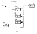
- a parallel rendering 100 system is shown as a representative embodiment of the present invention.
- Parallel rendering system 100 is intended to represent a sequential grouping of a series of similar, or dissimilar graphics pipelines.
- three graphics pipelines 102a through 102c are shown. Each of these graphics pipelines 102 is intended to be representative of a wide range of different graphics pipeline types.
- Graphics pipelines 102 are connected as a daisy chain sequence. This means that the output of each pipeline 102 (except the last pipeline 102c) is connected as an input to a subsequent pipeline 102. The output of the last pipeline 102c is connected to display device 104.
- Each pipeline 102 is connected to a host processor 106.
- Host processor 106 is intended to be representative of a wide range of different processor types. The connection between host processor 106 and graphics pipelines 102 is also intended to represent a wide range of different technologies such as bus interconnects and shared memory. Host processor 106 controls the execution of pipelines 102.
- graphics pipelines 102 Under the control of host processor 106, graphics pipelines 102 produce sequences of images for display on display 104. The production of images within pipelines 102 is synchronized. This means that graphics pipelines 102 produce images in a correct ordering (i.e., preceding images do not follow subsequent images).
- each graphics pipeline 102 includes a multiplexer 200.
- Multiplexer 200 has two inputs. The first of these is the digital video output of the pipeline 102 that includes the multiplexer 200. The second input of each multiplexer (except the first) is connected to the output of the multiplexer 200 in a preceding pipeline 102. The second input of the first multiplexer 200 is connected to a null device.
- Each pipeline 102 includes three state bits: a current bit 202, a next bit 204 and a ready disable bit 206.
- Current bit 202 directly controls the state of multiplexer 200. When current bit 202 is set, multiplexer 200 selects its first input. In this configuration, multiplexer 200 outputs the digital video output of the pipeline 102 in which it is included. For this reason, this configuration is known as local mode. When current bit 202 is not set, multiplexer 200 selects its second input. In this configuration, multiplexer 200 outputs the digital video data it receives from preceding pipelines 102. For this reason, this configuration is known as pass-through mode.
- Next bit 204 contains the next value for current bit 202.
- pipelines 102 transfer the value included in next bit 204 to current bit 202 as part of each swap event.
- each next bit 204 controls the next state (local or pass-through) of the pipeline 102 in which it is included.
- next bit 204 is set or cleared using a command sent by host processor 106. This allows a host application to dynamically select the next pipeline 102 to output video data.
- pipelines 102 are each connected to produce a common local ready signal 208.
- a pipeline 102 selected as the next pipeline 102 i.e., a pipeline 102 having a set next bit 204 asserts local ready signal 208 when it is ready to output its video data.
- Host processor 106 uses ready disable bits 206 to prevent all other pipelines 102 from asserting local ready signals 208.
- ready disable bits 206 are set or cleared using a command sent by host processor 106.
- Graphics pipelines 102 are connected to monitor the state of global ready signal 210.
- Global ready signal 210 is configured to act as a logical AND of its inputs. Within the example of Figure 2 the only input for global ready signal 210 is the common local ready signal 208 produced by graphics pipelines 102. As a result, within this example, global ready signal 210 enters an asserted state whenever one of graphics pipelines 102 asserts local ready signal 208. This means that global ready signal 210 become asserted whenever a pipeline 102 having a set next bit 204 becomes ready to output its video data.
- Graphics pipelines 102 sample the state of global ready signal 210 on a periodic, synchronized basis. Typically, this is accomplished by connecting each graphics pipeline 102 to a periodically repeating vertical synchronization signal. Using this system, the synchronization subsystems sample global ready signal 210 at the beginning of each pulse of the vertical synchronization signal.
- graphics pipelines 102 When graphics pipelines 102 discover that global ready signal 210 is in the asserted state, they initiate a swap event. During the swap event, each graphics pipeline 102 moves the value stored in its next bit 204 into its current bit 202. Each graphics pipeline 102 also clears its next bit 204. If the movement of next bit 204 sets current bit 202, multiplexer 200 enters local mode operation. In all other cases, multiplexer 200 either enters or stays in pass-through mode.
- an application process executing on host processor 106, allocates graphics primitives to at least some of the pipelines 102.
- the primitives correspond to a series of images that are to be generated by pipelines 102.
- the host application selects the pipeline 102 that is to render the first image portion 402a, 402b or 402c.
- the host application then sends commands to graphics pipelines 102 to set the next bit in the selected pipeline 102.
- the commands also set the disable ready bits in the remaining pipelines.
- the selected graphics pipeline 102 When the selected graphics pipeline 102 finishes rendering its graphics primitives, it asserts local swap ready 208. This causes global swap ready 210 to enter an asserted state. At the beginning of the next vertical sync pulse, the selected graphics pipelines 102 and all other graphics pipelines 102 sample global ready signal 210. Since global ready signal is asserted, a swap event is initiated.
- each graphics pipeline moves its next bit 204 to its current bit 202.
- next bit 204 is set. This causes the selected graphics pipeline 102 to enter local mode operation.
- the remaining graphics pipelines 102 have clear next bits 204. This causes these pipelines 102 to either enter or remain in pass-through mode operation.
- Host processor 106 continues the rendering process by repeatedly setting appropriate next bits 204 and appropriate ready disable bits 206.
- Host processor may also allocate new primitives to pipelines 102 that have completed rendering and outputting their video data. In this way, the present invention provides a flexible synchronization mechanism that allows a software application to selectively control the order or execution for pipelines 102.
- the present invention also provides for synchronized execution between sequences of graphics pipelines (such as the sequence of graphics pipelines 102 shown in Figure 2 ) and graphics pipelines that are configured to work in parallel with sequences of this type.
- An example of this type of configuration is shown in Figure 3.
- Figure 3 includes the three sequential pipelines 102a - 102c of Figure 2 . In this case, however, two additional graphics pipelines 102d and 102e are configured for parallel operation with the sequence of pipelines 102a - 102c.
- each that the three sequential pipelines 102a - 102c produce a series of images for a portion of display 104.
- the remaining pipelines 102d and 102e each provide images for additional portions of display 104.
- Sample image 400 is shown.
- Sample image 200 is subdivided into three portions 402a through 402c.
- these portions 402a, 402b, and 402c are contributed by the three sequential pipelines 102a - 102c, pipeline 102d and 102e, respectively.
- Synchronization between the three sequential pipelines 102a - 102c and pipelines 102d and 102e is achieved by configuring pipelines 102d and 102e to provide local swap ready signals when they are ready to output their video data. This ensures that the three sequential pipelines 102a - 102c will not begin swap event processing before pipelines 102d and 102e are ready. Pipelines 102d and 102e are also required to delay swap event processing until global ready signal 210 is asserted. This ensures that pipelines 102d and 102e will not begin swap event processing before the three sequential pipelines 102a - 102c are ready. In this way, the present allows pipelines grouped in sequence to operate in parallel with other pipelines and groups of pipelines.
Description
- The present invention relates generally to systems for computer graphics. More specifically, the present invention includes a method and apparatus for synchronizing the sequential operation of a group of graphics pipelines.
- Computer systems (and related devices) typically create three-dimensional images using a sequence of stages known as a graphics pipeline. During early pipeline stages, images are modeled using a mosaic-like approach where each image is composed of a collection of individual points, lines and polygons. These points, lines and polygons are know as primitives and a single image may require thousands, or even millions, of primitives. Each primitive is defined in terms of its shape and location as well as other attributes, such as color and texture.
- The graphics pipeline maps each primitive into a memory storage device known as a frame buffer. Each storage location within the frame buffer defines one pixel within the image being produced. The graphics pipeline performs the mapping process by determining which pixels (i.e., which frame buffer storage locations) are included within each primitive. Each pixel is then initialized to reflect the attributes of the primitive, or primitives in which it is included. In many cases, the graphics pipeline will further modify the pixel values in the frame buffer to apply texture, lighting and other effects to the graphics primitives.
- The task of rendering primitives to pixels can be very time consuming. This is especially true for complex images that include many primitives or require complex lighting, shading or other effects. The time consumed transforming primitives becomes problematic for applications, such as flight simulators and virtual reality environments, where rapid image generation is required.
- One method for improving the speed of the rendering process is to use multiple graphics pipelines. For this method, the task of rendering primitives is subdivided so that each pipeline performs some portion of the total task. One way of subdividing the rendering task is to assign a fixed portion of each image to a different pipeline. The pipelines operate in parallel and each pipeline processes the primitives that are included in its image portion.
- The parallel output of the various pipelines is combined for display. To be effective, this combination must be accomplished seamlessly, as though the image were being created by a single graphics pipeline. In general, this seamless integration requires that the output of each pipeline be synchronized. Otherwise, the pipelines produce output at somewhat random intervals. This can make the resulting images appear to be inaccurate or even incoherent.
- For some systems, the synchronization problem may be overcome through the use of a global ready signal. SILICON GRAPHICS INC. provides a signal of this type, known as SWAP_READY, for use with certain types of SGI computers. The SWAP_READY signal is physically connected to each graphics pipelines that is to be synchronized. Systems that are ready to output their image portion assert local ready signals. SWAP_READY functions as a logical AND of these local ready signal. As a result, SWAP_READY becomes asserted when all systems are ready to output their image portions. The graphics pipelines sample the state of the SWAP_READY signal on a periodic, synchronized basis. The pipelines output their image portions when they discover that SWAP_READY is high.
- A second way to combine multiple graphics pipelines is to subdivide the rendering task so that the pipelines operate in round-robin or sequential fasion. For this method, each pipeline contributes a succeeding image to a sequence of images. The sequential method has certain advantages when compared to the method where each image is partitioned between pipelines. One of these advantages is the ability to use less powerful graphics pipelines to produce a sequence of images at an accelerated rate. This is especially beneficial for flight simulators and other real time environments.
- To ensure image quality, sequential pipeline operation requires synchronization of the pipelines that are used to generate an image. Otherwise, there is a chance that the pipelines will output images out of order. For animation and simulation environments, this can cause the display to move unpredictably forward and backward in time. Unfortunately, a synchronization method, such as a global ready signal, is not available for systems using the sequential pipeline operation. As a result, complex software synchronization is required, increasing the difficulty of implementing systems of this type.
- For some applications it is desirable to use a combination of both of the previously described techniques for combining multiple graphics pipelines. This allows images to be partitioned into regions with each region using one or more pipelines connected in sequence. The sequential operation of each group of one or more pipelines proceeds in parallel with the operation with the remaining pipeline groups. This provides a flexible method for arranging graphics pipelines to match the image generation requirements of specific applications. Unfortunately, the lack of a synchronization method for sequential pipeline operation makes combination of these systems with other graphics pipelines difficult.
- Furthermore,
US-A-5 537 561 discloses a processor with a plurality of operational pipelines for performing parallel processing. The processor includes an instruction processing section with a plurality of instruction processing pipelines and an instruction processing control section with a plurality of instruction processing control pipelines. The instruction processing control section has an instruction issuing control section which issues decoded instructions after adding tags representing data dependency between successive instructions and a pipe lock signal generating section which generates pipe lock signals for locking the pipelines until further processing is allowed. - HIROYUKI SATO ET AL: "PARALLEL VISUAL COMPUTING ON THE AP1000: HARDWARE AND SOFTWARE", FUJITSU-SCIENTIFIC AND TECHNICAL JOURNAL,JP,FUJITSU LIMITED. KAWASAKI, vol. 29, no. 1, 21 March 1993 (1993-03-21), pages 41-49-41, XP000422963 ISSN: 0016-2523 disclose a video and parallel disk hardware option. The video hardware outputs HDTV-resolution images distributed in processor memory in real-time, and the parallel disk hardware processes large amount of data at high speed. Visualization software uses parallel processing to visualize at high speed, wherein task pipelining provides a flexible way to build up task configurations.
- Based on the preceding it may be appreciated that a need exists for an effective method for synchronizing multiple graphics pipelines that are configured to operate in a sequential fashion. A preferable solution to this problem would allow sequential graphics pipeline groups to operate in parallel with other pipeline groups.
- The invention is defined in claims 1, 6 and 9 respectively. Particular embodiments of the invention are set out in the dependent claims.
- An embodiment of the present invention includes a method and apparatus for synchronizing the operation of graphics pipelines. This method and apparatus allows graphics pipelines to be grouped for sequential operation and allows parallel execution between these pipeline groups. For a representative embodiment of the present invention, one or more graphics pipelines are connected as a daisy-chain sequence. This means that the output of each pipeline (except the last) is connected as an input to a subsequent pipeline. The output of the last pipeline is connected to a display device.
- Each pipeline may be configured to operate in two different modes: local and pass-through. Pipelines operating in local mode output their own digital video data (i.e., the pixel values generated by the graphics pipelines). Pipelines operating in pass-through mode output the video data that they receive from preceding pipelines.
- In operation, an application program configures the sequence of pipelines so that one pipeline operates in local mode. The remaining pipelines operate in pass-through mode. This causes the digital video output produced by the one pipeline to be passed through to the output device. At periodic intervals, the application program selects the next pipeline for operation in local mode. Shortly after the selected next pipeline becomes ready a swap event occurs. During the swap event, the selected next pipeline switches to local mode and the remaining pipeline either enter or stay in pass-through mode. In this way, the pipelines cooperate in sequential fashion to produce a sequence of images.
- The timing of swap events is based on the state of a global ready signal. The global ready signal represents a logical AND of a set of local ready signals. One of these local ready signals is produced by the selected next pipeline. This local ready signal functions as the local ready signal for the entire sequence of graphics pipelines. The remaining local ready signals are provided by any graphics pipelines that are configured to work in parallel with the sequence of graphics pipelines. The global ready signal becomes asserted when each of these local ready signals is asserted. This means that the selected next pipeline, and all pipelines that are configured to work in parallel with the selected next pipeline, are ready to begin outputting video data. All of the pipelines within the sequence of pipelines monitor the state of the global ready signal. When the global ready signal becomes asserted, a swap event is initiated.
- By generating the local ready signal in this fashion and using the global ready signal in this fashion, the sequence of pipelines synchronizes its own internal operation. The sequence of pipelines also operates in a mode that is compatible with the parallel operation of other graphics pipelines and groups of graphics pipelines.
- Advantages of the invention will be set forth, in part, in the description that follows and, in part, will be understood by those skilled in the art from the description herein. The advantages of the invention will be realized and attained by means of the elements and combinations particularly pointed out in the appended claims and equivalents.
- The accompanying drawings, that are incorporated in and constitute a part of this specification, illustrate several embodiments of the invention and, together with the description, serve to explain the principles of the invention.
-
Figure 1 is a block diagram showing three graphics pipelines configured to operate in sequence. -
Figure 2 is a block diagram showing the internal details of the pipeline sequence ofFigure 1 . -
Figure 3 is a block diagram showing the pipeline sequence ofFigure 1 operating in parallel with two graphics pipelines. -
Figure 4 is a block diagram showing a single image divided into three image portions. - Reference will now be made in detail to preferred embodiments of the invention, examples of which are illustrated in the accompanying drawings. Wherever convenient, the same reference numbers will be used throughout the drawings to refer to the same or like parts.
- An embodiment of the present invention includes a method and apparatus for synchronizing the operation of graphics pipelines. This method and apparatus allows graphics pipelines to be grouped for sequential operation and allows parallel execution between these pipeline groups. In
Figure 1 , aparallel rendering 100 system is shown as a representative embodiment of the present invention.Parallel rendering system 100 is intended to represent a sequential grouping of a series of similar, or dissimilar graphics pipelines. For the specific example ofFigure 1 , threegraphics pipelines 102a through 102c are shown. Each of these graphics pipelines 102 is intended to be representative of a wide range of different graphics pipeline types. Graphics pipelines 102 are connected as a daisy chain sequence. This means that the output of each pipeline 102 (except thelast pipeline 102c) is connected as an input to a subsequent pipeline 102. The output of thelast pipeline 102c is connected to displaydevice 104. - Each pipeline 102 is connected to a
host processor 106.Host processor 106 is intended to be representative of a wide range of different processor types. The connection betweenhost processor 106 and graphics pipelines 102 is also intended to represent a wide range of different technologies such as bus interconnects and shared memory.Host processor 106 controls the execution of pipelines 102. - Under the control of
host processor 106, graphics pipelines 102 produce sequences of images for display ondisplay 104. The production of images within pipelines 102 is synchronized. This means that graphics pipelines 102 produce images in a correct ordering (i.e., preceding images do not follow subsequent images). - The internal details that provide synchronized operation are better appreciated by reference to
Figure 2 . InFigure 2 , it may be seen that each graphics pipeline 102 includes amultiplexer 200.Multiplexer 200 has two inputs. The first of these is the digital video output of the pipeline 102 that includes themultiplexer 200. The second input of each multiplexer (except the first) is connected to the output of themultiplexer 200 in a preceding pipeline 102. The second input of thefirst multiplexer 200 is connected to a null device. - Each pipeline 102 includes three state bits: a
current bit 202, anext bit 204 and a ready disablebit 206.Current bit 202 directly controls the state ofmultiplexer 200. Whencurrent bit 202 is set,multiplexer 200 selects its first input. In this configuration,multiplexer 200 outputs the digital video output of the pipeline 102 in which it is included. For this reason, this configuration is known as local mode. Whencurrent bit 202 is not set,multiplexer 200 selects its second input. In this configuration,multiplexer 200 outputs the digital video data it receives from preceding pipelines 102. For this reason, this configuration is known as pass-through mode. -
Next bit 204 contains the next value forcurrent bit 202. As will be described in more detail, pipelines 102 transfer the value included innext bit 204 tocurrent bit 202 as part of each swap event. In this way, eachnext bit 204 controls the next state (local or pass-through) of the pipeline 102 in which it is included. For the particular embodiment being described,next bit 204 is set or cleared using a command sent byhost processor 106. This allows a host application to dynamically select the next pipeline 102 to output video data. - As shown in
Figure 2 , pipelines 102 are each connected to produce a common localready signal 208. A pipeline 102 selected as the next pipeline 102 (i.e., a pipeline 102 having a set next bit 204) asserts localready signal 208 when it is ready to output its video data.Host processor 106 uses ready disablebits 206 to prevent all other pipelines 102 from asserting local ready signals 208. For the particular embodiment being described, ready disablebits 206 are set or cleared using a command sent byhost processor 106. - Graphics pipelines 102 are connected to monitor the state of global
ready signal 210. Globalready signal 210 is configured to act as a logical AND of its inputs. Within the example ofFigure 2 the only input for globalready signal 210 is the common localready signal 208 produced by graphics pipelines 102. As a result, within this example, globalready signal 210 enters an asserted state whenever one of graphics pipelines 102 asserts localready signal 208. This means that globalready signal 210 become asserted whenever a pipeline 102 having a setnext bit 204 becomes ready to output its video data. Graphics pipelines 102 sample the state of globalready signal 210 on a periodic, synchronized basis. Typically, this is accomplished by connecting each graphics pipeline 102 to a periodically repeating vertical synchronization signal. Using this system, the synchronization subsystems sample globalready signal 210 at the beginning of each pulse of the vertical synchronization signal. - When graphics pipelines 102 discover that global
ready signal 210 is in the asserted state, they initiate a swap event. During the swap event, each graphics pipeline 102 moves the value stored in itsnext bit 204 into itscurrent bit 202. Each graphics pipeline 102 also clears itsnext bit 204. If the movement ofnext bit 204 setscurrent bit 202,multiplexer 200 enters local mode operation. In all other cases,multiplexer 200 either enters or stays in pass-through mode. - During operation, an application process, executing on
host processor 106, allocates graphics primitives to at least some of the pipelines 102. The primitives correspond to a series of images that are to be generated by pipelines 102. The host application then selects the pipeline 102 that is to render thefirst image portion - When the selected graphics pipeline 102 finishes rendering its graphics primitives, it asserts local swap ready 208. This causes global swap ready 210 to enter an asserted state. At the beginning of the next vertical sync pulse, the selected graphics pipelines 102 and all other graphics pipelines 102 sample global
ready signal 210. Since global ready signal is asserted, a swap event is initiated. - During the swap event, each graphics pipeline moves its
next bit 204 to itscurrent bit 202. In the case of the selected graphics pipeline,next bit 204 is set. This causes the selected graphics pipeline 102 to enter local mode operation. The remaining graphics pipelines 102 have clearnext bits 204. This causes these pipelines 102 to either enter or remain in pass-through mode operation. -
Host processor 106 continues the rendering process by repeatedly setting appropriatenext bits 204 and appropriate ready disablebits 206. Host processor may also allocate new primitives to pipelines 102 that have completed rendering and outputting their video data. In this way, the present invention provides a flexible synchronization mechanism that allows a software application to selectively control the order or execution for pipelines 102. - The present invention also provides for synchronized execution between sequences of graphics pipelines (such as the sequence of graphics pipelines 102 shown in
Figure 2 ) and graphics pipelines that are configured to work in parallel with sequences of this type. An example of this type of configuration is shown inFigure 3. Figure 3 , includes the threesequential pipelines 102a - 102c ofFigure 2 . In this case, however, twoadditional graphics pipelines pipelines 102a - 102c. - For the purposes of this example, it is assumed that each that the three
sequential pipelines 102a - 102c produce a series of images for a portion ofdisplay 104. The remainingpipelines display 104. This can be appreciated by reference toFigure 4 where asample image 400 is shown.Sample image 200 is subdivided into threeportions 402a through 402c. For the purposes of the example ofFigure 3 , it may be assumed that theseportions sequential pipelines 102a - 102c,pipeline - Synchronization between the three
sequential pipelines 102a - 102c andpipelines pipelines sequential pipelines 102a - 102c will not begin swap event processing beforepipelines Pipelines ready signal 210 is asserted. This ensures thatpipelines sequential pipelines 102a - 102c are ready. In this way, the present allows pipelines grouped in sequence to operate in parallel with other pipelines and groups of pipelines. - Other embodiments will be apparent to those skilled in the art from consideration of the specification and practice of the invention disclosed herein. It is intended that the specification and examples be considered as exemplary only, with a true scope of the invention being indicated by the following claims.
Claims (11)
- A method of synchronizing the operation of a sequence of serially connected graphics pipelines (102) with a global ready signal (210), the method comprising:designating, by a host processor (106), a next graphics pipeline (102) within said sequence of graphics pipelines;waiting, by the next graphics pipeline (102), until the next graphics pipeline is ready to output video data to be produced by the next graphics pipeline;asserting, by the next graphics pipeline (102), a local ready signal (208) indicating that the next graphics pipeline is ready to output video data;waiting, by the next graphics pipeline (102), until the global ready signal (210) enters an asserted state;outputting, by the next graphics pipeline (102), video data produced by the next graphics pipeline; andenabling other graphics pipelines (102) within said sequence of graphics pipelines that are not the next graphics pipelines to pass through the video data produced by the next graphics pipeline.
- A method as recited in claim 1, further comprising, performed by the host processor (106), disabling the assertion of local ready signals (208) by graphics pipelines (102) within said sequence of graphics pipelines that are not the next graphics pipeline.
- A method as recited in claim 1 or 2, wherein the graphics pipelines (102) are connected to monitor the state of a periodically repeating vertical synchronization signal and where the step of waiting, by the next graphics pipeline (102), until the global ready signal (210) enters an asserted state further comprises sampling the global synchronization at the start of each pulse of the vertical synchronization signal.
- A method as recited in any of claims 1-3, wherein each graphics pipeline (102) in said sequence of graphics pipelines has an associated next bit (204), and wherein the step of designating, by a host processor (106), a next graphics pipeline further comprises setting, by the host processor (106), the next bit for the next graphics pipeline.
- A method as recited in any of claims 1-4, wherein the global ready signal (210) is formed as a logical AND of the local ready signal (208) and other local ready signals (208) produced by other graphics pipelines (102).
- An electronically-readable medium having stored thereon computer-readable code to permit a computer to effect a method of synchronizing the operation of:designating, by a host processor (106), a next graphics pipeline (102) within a serially connected sequence of graphics pipelines;waiting, by the next graphics pipeline (102), until the next graphics pipeline is ready to output video data to be produced by the next graphics pipeline;asserting, by the next graphics pipeline (102), a local ready signal (208) indicating that the next graphics pipeline is ready to output video data;waiting, by the next graphics pipeline (102), until the global ready signal (210) enters an asserted state;outputting, by the next graphics pipeline (102), video data produced by the next graphics pipeline; andenabling other graphics pipelines (102) within said sequence of graphics pipelines that are not the next graphics pipelines to pass through the video data produced by the next graphics pipeline.
- An electronically-readable medium as recited in claim 6, further comprising computer-readable code disabling, by a host processor (106), the assertion of local ready signals (208) by graphics pipelines (102) within said sequence of graphics pipelines that are not the next graphics pipeline.
- An electronically-readable medium as recited in claim 6 or 7, wherein the global ready signal (210) is formed as a logical AND of the local ready signal (208) and other local ready signals (208) produced by other sequences of graphics pipelines.
- A system adapted to synchronize the operation of a sequence of serially connected graphics pipelines with a global ready signal, the system comprising:means (106) adapted to designate a next graphics pipeline (102) within the sequence of graphics pipelines (102);means (106) adapted to wait until the next graphics pipeline (102) is ready to output video data to be produced by the next graphics pipeline;means (106) adapted to assert a local ready signal (208) indicating that the next graphics pipeline is ready to output video data;means (106) adapted to wait until the global ready signal (210) enters an asserted state;means (106, 200, 202) adapted to output, by the next graphics pipeline, video data produced by the next graphics pipeline; andmeans (106, 200,202) adapted to enable other graphics pipelines within said sequence of graphics pipelines that are not the next graphics pipelines to pass through the video data produced by the next graphics pipeline.
- A system as recited in claim 9, further comprising:means (106) adapted to disable the assertion of local ready signals (208) by graphics pipelines (102) within said sequence of graphics pipelines that are not the next graphics pipeline (102).
- A system as recited in claim 9 or 10, wherein the global ready signal (210) is formed as a logical AND of the local ready signal (208) and other local ready signals (208) produced by other graphics pipelines (102).
Applications Claiming Priority (3)
| Application Number | Priority Date | Filing Date | Title |
|---|---|---|---|
| US227227 | 1999-01-08 | ||
| US09/227,227 US6329996B1 (en) | 1999-01-08 | 1999-01-08 | Method and apparatus for synchronizing graphics pipelines |
| PCT/US2000/000549 WO2000041136A1 (en) | 1999-01-08 | 2000-01-07 | Method and apparatus for synchronizing graphics pipelines |
Publications (2)
| Publication Number | Publication Date |
|---|---|
| EP1147489A1 EP1147489A1 (en) | 2001-10-24 |
| EP1147489B1 true EP1147489B1 (en) | 2015-12-02 |
Family
ID=22852280
Family Applications (1)
| Application Number | Title | Priority Date | Filing Date |
|---|---|---|---|
| EP00903207.9A Expired - Lifetime EP1147489B1 (en) | 1999-01-08 | 2000-01-07 | Method and apparatus for synchronizing graphics pipelines |
Country Status (5)
| Country | Link |
|---|---|
| US (1) | US6329996B1 (en) |
| EP (1) | EP1147489B1 (en) |
| JP (1) | JP4249397B2 (en) |
| AU (1) | AU2498700A (en) |
| WO (1) | WO2000041136A1 (en) |
Families Citing this family (56)
| Publication number | Priority date | Publication date | Assignee | Title |
|---|---|---|---|---|
| JP3169933B2 (en) * | 1999-03-16 | 2001-05-28 | 四国日本電気ソフトウェア株式会社 | Parallel drawing device |
| US6446155B1 (en) * | 1999-06-30 | 2002-09-03 | Logitech Europe S. A. | Resource bus interface |
| US6924806B1 (en) * | 1999-08-06 | 2005-08-02 | Microsoft Corporation | Video card with interchangeable connector module |
| US6919897B1 (en) | 1999-08-06 | 2005-07-19 | Microsoft Corporation | System and method for pre-processing a video signal |
| US6885381B1 (en) * | 2000-08-04 | 2005-04-26 | Microsoft Corporation | System and method for producing a video signal |
| US6847358B1 (en) | 1999-08-06 | 2005-01-25 | Microsoft Corporation | Workstation for processing and producing a video signal |
| US6924807B2 (en) * | 2000-03-23 | 2005-08-02 | Sony Computer Entertainment Inc. | Image processing apparatus and method |
| US8095508B2 (en) | 2000-04-07 | 2012-01-10 | Washington University | Intelligent data storage and processing using FPGA devices |
| US7139743B2 (en) | 2000-04-07 | 2006-11-21 | Washington University | Associative database scanning and information retrieval using FPGA devices |
| US6711558B1 (en) | 2000-04-07 | 2004-03-23 | Washington University | Associative database scanning and information retrieval |
| US7119809B1 (en) * | 2000-05-15 | 2006-10-10 | S3 Graphics Co., Ltd. | Parallel architecture for graphics primitive decomposition |
| US6867781B1 (en) * | 2000-08-23 | 2005-03-15 | Nintendo Co., Ltd. | Graphics pipeline token synchronization |
| JP3580789B2 (en) * | 2000-10-10 | 2004-10-27 | 株式会社ソニー・コンピュータエンタテインメント | Data communication system and method, computer program, recording medium |
| JP3688618B2 (en) * | 2000-10-10 | 2005-08-31 | 株式会社ソニー・コンピュータエンタテインメント | Data processing system, data processing method, computer program, and recording medium |
| US6947053B2 (en) * | 2001-09-27 | 2005-09-20 | Intel Corporation | Texture engine state variable synchronizer |
| US6920618B2 (en) * | 2001-12-21 | 2005-07-19 | Hewlett-Packard Development Company, L.P. | System and method for configuring graphics pipelines in a computer graphical display system |
| US6833831B2 (en) * | 2002-02-26 | 2004-12-21 | Sun Microsystems, Inc. | Synchronizing data streams in a graphics processor |
| US10572824B2 (en) | 2003-05-23 | 2020-02-25 | Ip Reservoir, Llc | System and method for low latency multi-functional pipeline with correlation logic and selectively activated/deactivated pipelined data processing engines |
| AU2004290281A1 (en) | 2003-05-23 | 2005-05-26 | Washington University | Intelligent data storage and processing using FPGA devices |
| US20080211816A1 (en) * | 2003-07-15 | 2008-09-04 | Alienware Labs. Corp. | Multiple parallel processor computer graphics system |
| US7119808B2 (en) * | 2003-07-15 | 2006-10-10 | Alienware Labs Corp. | Multiple parallel processor computer graphics system |
| US7782325B2 (en) * | 2003-10-22 | 2010-08-24 | Alienware Labs Corporation | Motherboard for supporting multiple graphics cards |
| US7721118B1 (en) | 2004-09-27 | 2010-05-18 | Nvidia Corporation | Optimizing power and performance for multi-processor graphics processing |
| US7477256B1 (en) * | 2004-11-17 | 2009-01-13 | Nvidia Corporation | Connecting graphics adapters for scalable performance |
| US7576745B1 (en) | 2004-11-17 | 2009-08-18 | Nvidia Corporation | Connecting graphics adapters |
| US8066515B2 (en) * | 2004-11-17 | 2011-11-29 | Nvidia Corporation | Multiple graphics adapter connection systems |
| US8134568B1 (en) | 2004-12-15 | 2012-03-13 | Nvidia Corporation | Frame buffer region redirection for multiple graphics adapters |
| US8212831B1 (en) | 2004-12-15 | 2012-07-03 | Nvidia Corporation | Broadcast aperture remapping for multiple graphics adapters |
| US7525549B1 (en) * | 2004-12-16 | 2009-04-28 | Nvidia Corporation | Display balance/metering |
| US7372465B1 (en) | 2004-12-17 | 2008-05-13 | Nvidia Corporation | Scalable graphics processing for remote display |
| US7917299B2 (en) | 2005-03-03 | 2011-03-29 | Washington University | Method and apparatus for performing similarity searching on a data stream with respect to a query string |
| US10026140B2 (en) | 2005-06-10 | 2018-07-17 | Nvidia Corporation | Using a scalable graphics system to enable a general-purpose multi-user computer system |
| US8817029B2 (en) * | 2005-10-26 | 2014-08-26 | Via Technologies, Inc. | GPU pipeline synchronization and control system and method |
| US7702629B2 (en) | 2005-12-02 | 2010-04-20 | Exegy Incorporated | Method and device for high performance regular expression pattern matching |
| WO2007121035A2 (en) | 2006-03-23 | 2007-10-25 | Exegy Incorporated | Method and system for high throughput blockwise independent encryption/decryption |
| US7921046B2 (en) | 2006-06-19 | 2011-04-05 | Exegy Incorporated | High speed processing of financial information using FPGA devices |
| US8326819B2 (en) | 2006-11-13 | 2012-12-04 | Exegy Incorporated | Method and system for high performance data metatagging and data indexing using coprocessors |
| US20080276067A1 (en) * | 2007-05-01 | 2008-11-06 | Via Technologies, Inc. | Method and Apparatus for Page Table Pre-Fetching in Zero Frame Display Channel |
| EP2186250B1 (en) | 2007-08-31 | 2019-03-27 | IP Reservoir, LLC | Method and apparatus for hardware-accelerated encryption/decryption |
| US10229453B2 (en) | 2008-01-11 | 2019-03-12 | Ip Reservoir, Llc | Method and system for low latency basket calculation |
| US8374986B2 (en) | 2008-05-15 | 2013-02-12 | Exegy Incorporated | Method and system for accelerated stream processing |
| JP5871619B2 (en) | 2008-12-15 | 2016-03-01 | アイ・ピー・リザブワー・エル・エル・シー | Method and apparatus for high-speed processing of financial market depth data |
| US9190012B2 (en) * | 2009-12-23 | 2015-11-17 | Ati Technologies Ulc | Method and system for improving display underflow using variable HBLANK |
| WO2012079041A1 (en) | 2010-12-09 | 2012-06-14 | Exegy Incorporated | Method and apparatus for managing orders in financial markets |
| US9047243B2 (en) | 2011-12-14 | 2015-06-02 | Ip Reservoir, Llc | Method and apparatus for low latency data distribution |
| US10650452B2 (en) | 2012-03-27 | 2020-05-12 | Ip Reservoir, Llc | Offload processing of data packets |
| US10121196B2 (en) | 2012-03-27 | 2018-11-06 | Ip Reservoir, Llc | Offload processing of data packets containing financial market data |
| US11436672B2 (en) | 2012-03-27 | 2022-09-06 | Exegy Incorporated | Intelligent switch for processing financial market data |
| US9990393B2 (en) | 2012-03-27 | 2018-06-05 | Ip Reservoir, Llc | Intelligent feed switch |
| US9633093B2 (en) | 2012-10-23 | 2017-04-25 | Ip Reservoir, Llc | Method and apparatus for accelerated format translation of data in a delimited data format |
| US9633097B2 (en) | 2012-10-23 | 2017-04-25 | Ip Reservoir, Llc | Method and apparatus for record pivoting to accelerate processing of data fields |
| CA2887022C (en) | 2012-10-23 | 2021-05-04 | Ip Reservoir, Llc | Method and apparatus for accelerated format translation of data in a delimited data format |
| US8941676B2 (en) * | 2012-10-26 | 2015-01-27 | Nvidia Corporation | On-chip anti-alias resolve in a cache tiling architecture |
| WO2015164639A1 (en) | 2014-04-23 | 2015-10-29 | Ip Reservoir, Llc | Method and apparatus for accelerated data translation |
| US10942943B2 (en) | 2015-10-29 | 2021-03-09 | Ip Reservoir, Llc | Dynamic field data translation to support high performance stream data processing |
| EP3560135A4 (en) | 2016-12-22 | 2020-08-05 | IP Reservoir, LLC | Pipelines for hardware-accelerated machine learning |
Family Cites Families (9)
| Publication number | Priority date | Publication date | Assignee | Title |
|---|---|---|---|---|
| JP2911278B2 (en) * | 1990-11-30 | 1999-06-23 | 松下電器産業株式会社 | Processor |
| US5706415A (en) * | 1991-12-20 | 1998-01-06 | Apple Computer, Inc. | Method and apparatus for distributed interpolation of pixel shading parameter values |
| US5598525A (en) * | 1995-01-23 | 1997-01-28 | Cirrus Logic, Inc. | Apparatus, systems and methods for controlling graphics and video data in multimedia data processing and display systems |
| US5917502A (en) * | 1995-12-06 | 1999-06-29 | Intergraph Corporation | Peer-to-peer parallel processing graphics accelerator |
| US5861893A (en) * | 1997-05-27 | 1999-01-19 | Intel Corporation | System and method for graphics data concurrency and coherency |
| US6122000A (en) * | 1997-06-03 | 2000-09-19 | Hewlett Packard Company | Synchronization of left/right channel display and vertical refresh in multi-display stereoscopic computer graphics systems |
| US5999183A (en) * | 1997-07-10 | 1999-12-07 | Silicon Engineering, Inc. | Apparatus for creating a scalable graphics system with efficient memory and bandwidth usage |
| US5995121A (en) * | 1997-10-16 | 1999-11-30 | Hewlett-Packard Company | Multiple graphics pipeline integration with a windowing system through the use of a high speed interconnect to the frame buffer |
| US6570579B1 (en) * | 1998-11-09 | 2003-05-27 | Broadcom Corporation | Graphics display system |
-
1999
- 1999-01-08 US US09/227,227 patent/US6329996B1/en not_active Expired - Lifetime
-
2000
- 2000-01-07 AU AU24987/00A patent/AU2498700A/en not_active Abandoned
- 2000-01-07 WO PCT/US2000/000549 patent/WO2000041136A1/en active Application Filing
- 2000-01-07 EP EP00903207.9A patent/EP1147489B1/en not_active Expired - Lifetime
- 2000-01-07 JP JP2000592791A patent/JP4249397B2/en not_active Expired - Lifetime
Also Published As
| Publication number | Publication date |
|---|---|
| WO2000041136A1 (en) | 2000-07-13 |
| JP2002534750A (en) | 2002-10-15 |
| JP4249397B2 (en) | 2009-04-02 |
| US6329996B1 (en) | 2001-12-11 |
| EP1147489A1 (en) | 2001-10-24 |
| AU2498700A (en) | 2000-07-24 |
Similar Documents
| Publication | Publication Date | Title |
|---|---|---|
| EP1147489B1 (en) | Method and apparatus for synchronizing graphics pipelines | |
| US5185599A (en) | Local display bus architecture and communications method for Raster display | |
| US7522171B1 (en) | On-the-fly reordering of 32-bit per component texture images in a multi-cycle data transfer | |
| JP2705003B2 (en) | Apparatus and method for processing two graphic data streams simultaneously | |
| US6535216B1 (en) | Multi-processor graphics accelerator | |
| US7447873B1 (en) | Multithreaded SIMD parallel processor with loading of groups of threads | |
| US7975272B2 (en) | Thread queuing method and apparatus | |
| JPH05282458A (en) | Plural extensible image buffers for graphics system | |
| US6947053B2 (en) | Texture engine state variable synchronizer | |
| GB2211706A (en) | Local display bus architecture and communications method for raster display | |
| US5091721A (en) | Acoustic display generator | |
| US7629978B1 (en) | Multichip rendering with state control | |
| US6166743A (en) | Method and system for improved z-test during image rendering | |
| JPH04219859A (en) | Harware distributor which distributes series-instruction-stream data to parallel processors | |
| GB2488196A (en) | A tile-based graphics system | |
| EP0150910A2 (en) | Digital image frame processor | |
| US6157393A (en) | Apparatus and method of directing graphical data to a display device | |
| US8941669B1 (en) | Split push buffer rendering for scalability | |
| JP3098342B2 (en) | Processing order specification method for parallel processing equipment | |
| US6795075B1 (en) | Graphic processor having multiple geometric operation units and method of processing data thereby | |
| CA2855819C (en) | Graphics processing apparatus, display apparatus for an aircraft cockpit, and method for displaying graphical data | |
| US6950106B2 (en) | 3-dimensional graphic plotting apparatus | |
| US7489315B1 (en) | Pixel stream assembly for raster operations | |
| JP2002183751A (en) | Graphic data rendering method and device | |
| JPH1124652A (en) | Drawing synchronization method in pattern processing system |
Legal Events
| Date | Code | Title | Description |
|---|---|---|---|
| PUAI | Public reference made under article 153(3) epc to a published international application that has entered the european phase |
Free format text: ORIGINAL CODE: 0009012 |
|
| 17P | Request for examination filed |
Effective date: 20010808 |
|
| AK | Designated contracting states |
Kind code of ref document: A1 Designated state(s): AT BE CH CY DE DK ES FI FR GB GR IE IT LI LU MC NL PT SE |
|
| RAP1 | Party data changed (applicant data changed or rights of an application transferred) |
Owner name: MICROSOFT CORPORATION |
|
| 17Q | First examination report despatched |
Effective date: 20061108 |
|
| RAP1 | Party data changed (applicant data changed or rights of an application transferred) |
Owner name: MICROSOFT TECHNOLOGY LICENSING, LLC |
|
| GRAP | Despatch of communication of intention to grant a patent |
Free format text: ORIGINAL CODE: EPIDOSNIGR1 |
|
| INTG | Intention to grant announced |
Effective date: 20150624 |
|
| GRAS | Grant fee paid |
Free format text: ORIGINAL CODE: EPIDOSNIGR3 |
|
| GRAA | (expected) grant |
Free format text: ORIGINAL CODE: 0009210 |
|
| AK | Designated contracting states |
Kind code of ref document: B1 Designated state(s): AT BE CH CY DE DK ES FI FR GB GR IE IT LI LU MC NL PT SE |
|
| REG | Reference to a national code |
Ref country code: GB Ref legal event code: FG4D |
|
| REG | Reference to a national code |
Ref country code: AT Ref legal event code: REF Ref document number: 763925 Country of ref document: AT Kind code of ref document: T Effective date: 20151215 Ref country code: CH Ref legal event code: EP |
|
| REG | Reference to a national code |
Ref country code: FR Ref legal event code: PLFP Year of fee payment: 17 |
|
| REG | Reference to a national code |
Ref country code: IE Ref legal event code: FG4D |
|
| REG | Reference to a national code |
Ref country code: DE Ref legal event code: R096 Ref document number: 60049141 Country of ref document: DE |
|
| PGFP | Annual fee paid to national office [announced via postgrant information from national office to epo] |
Ref country code: FR Payment date: 20151223 Year of fee payment: 17 |
|
| REG | Reference to a national code |
Ref country code: NL Ref legal event code: MP Effective date: 20160302 |
|
| REG | Reference to a national code |
Ref country code: AT Ref legal event code: MK05 Ref document number: 763925 Country of ref document: AT Kind code of ref document: T Effective date: 20151202 |
|
| PG25 | Lapsed in a contracting state [announced via postgrant information from national office to epo] |
Ref country code: ES Free format text: LAPSE BECAUSE OF FAILURE TO SUBMIT A TRANSLATION OF THE DESCRIPTION OR TO PAY THE FEE WITHIN THE PRESCRIBED TIME-LIMIT Effective date: 20151202 |
|
| PGFP | Annual fee paid to national office [announced via postgrant information from national office to epo] |
Ref country code: DE Payment date: 20151229 Year of fee payment: 17 |
|
| PG25 | Lapsed in a contracting state [announced via postgrant information from national office to epo] |
Ref country code: SE Free format text: LAPSE BECAUSE OF FAILURE TO SUBMIT A TRANSLATION OF THE DESCRIPTION OR TO PAY THE FEE WITHIN THE PRESCRIBED TIME-LIMIT Effective date: 20151202 Ref country code: FI Free format text: LAPSE BECAUSE OF FAILURE TO SUBMIT A TRANSLATION OF THE DESCRIPTION OR TO PAY THE FEE WITHIN THE PRESCRIBED TIME-LIMIT Effective date: 20151202 Ref country code: BE Free format text: LAPSE BECAUSE OF NON-PAYMENT OF DUE FEES Effective date: 20160131 Ref country code: GR Free format text: LAPSE BECAUSE OF FAILURE TO SUBMIT A TRANSLATION OF THE DESCRIPTION OR TO PAY THE FEE WITHIN THE PRESCRIBED TIME-LIMIT Effective date: 20160303 Ref country code: NL Free format text: LAPSE BECAUSE OF FAILURE TO SUBMIT A TRANSLATION OF THE DESCRIPTION OR TO PAY THE FEE WITHIN THE PRESCRIBED TIME-LIMIT Effective date: 20151202 Ref country code: AT Free format text: LAPSE BECAUSE OF FAILURE TO SUBMIT A TRANSLATION OF THE DESCRIPTION OR TO PAY THE FEE WITHIN THE PRESCRIBED TIME-LIMIT Effective date: 20151202 |
|
| PGFP | Annual fee paid to national office [announced via postgrant information from national office to epo] |
Ref country code: GB Payment date: 20160106 Year of fee payment: 17 |
|
| PG25 | Lapsed in a contracting state [announced via postgrant information from national office to epo] |
Ref country code: IT Free format text: LAPSE BECAUSE OF FAILURE TO SUBMIT A TRANSLATION OF THE DESCRIPTION OR TO PAY THE FEE WITHIN THE PRESCRIBED TIME-LIMIT Effective date: 20151202 |
|
| PG25 | Lapsed in a contracting state [announced via postgrant information from national office to epo] |
Ref country code: LU Free format text: LAPSE BECAUSE OF FAILURE TO SUBMIT A TRANSLATION OF THE DESCRIPTION OR TO PAY THE FEE WITHIN THE PRESCRIBED TIME-LIMIT Effective date: 20160107 Ref country code: PT Free format text: LAPSE BECAUSE OF FAILURE TO SUBMIT A TRANSLATION OF THE DESCRIPTION OR TO PAY THE FEE WITHIN THE PRESCRIBED TIME-LIMIT Effective date: 20160404 |
|
| REG | Reference to a national code |
Ref country code: CH Ref legal event code: PL |
|
| REG | Reference to a national code |
Ref country code: DE Ref legal event code: R097 Ref document number: 60049141 Country of ref document: DE |
|
| PG25 | Lapsed in a contracting state [announced via postgrant information from national office to epo] |
Ref country code: MC Free format text: LAPSE BECAUSE OF FAILURE TO SUBMIT A TRANSLATION OF THE DESCRIPTION OR TO PAY THE FEE WITHIN THE PRESCRIBED TIME-LIMIT Effective date: 20151202 |
|
| PLBE | No opposition filed within time limit |
Free format text: ORIGINAL CODE: 0009261 |
|
| STAA | Information on the status of an ep patent application or granted ep patent |
Free format text: STATUS: NO OPPOSITION FILED WITHIN TIME LIMIT |
|
| PG25 | Lapsed in a contracting state [announced via postgrant information from national office to epo] |
Ref country code: DK Free format text: LAPSE BECAUSE OF FAILURE TO SUBMIT A TRANSLATION OF THE DESCRIPTION OR TO PAY THE FEE WITHIN THE PRESCRIBED TIME-LIMIT Effective date: 20151202 Ref country code: LI Free format text: LAPSE BECAUSE OF NON-PAYMENT OF DUE FEES Effective date: 20160131 Ref country code: CH Free format text: LAPSE BECAUSE OF NON-PAYMENT OF DUE FEES Effective date: 20160131 |
|
| REG | Reference to a national code |
Ref country code: IE Ref legal event code: MM4A |
|
| 26N | No opposition filed |
Effective date: 20160905 |
|
| PG25 | Lapsed in a contracting state [announced via postgrant information from national office to epo] |
Ref country code: BE Free format text: LAPSE BECAUSE OF FAILURE TO SUBMIT A TRANSLATION OF THE DESCRIPTION OR TO PAY THE FEE WITHIN THE PRESCRIBED TIME-LIMIT Effective date: 20151202 |
|
| PG25 | Lapsed in a contracting state [announced via postgrant information from national office to epo] |
Ref country code: IE Free format text: LAPSE BECAUSE OF NON-PAYMENT OF DUE FEES Effective date: 20160107 |
|
| REG | Reference to a national code |
Ref country code: DE Ref legal event code: R119 Ref document number: 60049141 Country of ref document: DE |
|
| GBPC | Gb: european patent ceased through non-payment of renewal fee |
Effective date: 20170107 |
|
| REG | Reference to a national code |
Ref country code: FR Ref legal event code: ST Effective date: 20170929 |
|
| PG25 | Lapsed in a contracting state [announced via postgrant information from national office to epo] |
Ref country code: FR Free format text: LAPSE BECAUSE OF NON-PAYMENT OF DUE FEES Effective date: 20170131 |
|
| PG25 | Lapsed in a contracting state [announced via postgrant information from national office to epo] |
Ref country code: GB Free format text: LAPSE BECAUSE OF NON-PAYMENT OF DUE FEES Effective date: 20170107 Ref country code: DE Free format text: LAPSE BECAUSE OF NON-PAYMENT OF DUE FEES Effective date: 20170801 |
|
| PG25 | Lapsed in a contracting state [announced via postgrant information from national office to epo] |
Ref country code: CY Free format text: LAPSE BECAUSE OF FAILURE TO SUBMIT A TRANSLATION OF THE DESCRIPTION OR TO PAY THE FEE WITHIN THE PRESCRIBED TIME-LIMIT Effective date: 20151202 |