EP1145235B1 - Variable speed recording method for a magnetic tape drive - Google Patents
Variable speed recording method for a magnetic tape drive Download PDFInfo
- Publication number
- EP1145235B1 EP1145235B1 EP99955108A EP99955108A EP1145235B1 EP 1145235 B1 EP1145235 B1 EP 1145235B1 EP 99955108 A EP99955108 A EP 99955108A EP 99955108 A EP99955108 A EP 99955108A EP 1145235 B1 EP1145235 B1 EP 1145235B1
- Authority
- EP
- European Patent Office
- Prior art keywords
- tape
- speed
- data
- track
- transport speed
- Prior art date
- Legal status (The legal status is an assumption and is not a legal conclusion. Google has not performed a legal analysis and makes no representation as to the accuracy of the status listed.)
- Expired - Lifetime
Links
Images


Classifications
-
- G—PHYSICS
- G11—INFORMATION STORAGE
- G11B—INFORMATION STORAGE BASED ON RELATIVE MOVEMENT BETWEEN RECORD CARRIER AND TRANSDUCER
- G11B5/00—Recording by magnetisation or demagnetisation of a record carrier; Reproducing by magnetic means; Record carriers therefor
- G11B5/008—Recording on, or reproducing or erasing from, magnetic tapes, sheets, e.g. cards, or wires
- G11B5/00813—Recording on, or reproducing or erasing from, magnetic tapes, sheets, e.g. cards, or wires magnetic tapes
- G11B5/00847—Recording on, or reproducing or erasing from, magnetic tapes, sheets, e.g. cards, or wires magnetic tapes on transverse tracks
- G11B5/0086—Recording on, or reproducing or erasing from, magnetic tapes, sheets, e.g. cards, or wires magnetic tapes on transverse tracks using cyclically driven heads providing segmented tracks
-
- G—PHYSICS
- G11—INFORMATION STORAGE
- G11B—INFORMATION STORAGE BASED ON RELATIVE MOVEMENT BETWEEN RECORD CARRIER AND TRANSDUCER
- G11B15/00—Driving, starting or stopping record carriers of filamentary or web form; Driving both such record carriers and heads; Guiding such record carriers or containers therefor; Control thereof; Control of operating function
- G11B15/02—Control of operating function, e.g. switching from recording to reproducing
- G11B15/04—Preventing, inhibiting, or warning against accidental erasing or double recording
-
- G—PHYSICS
- G11—INFORMATION STORAGE
- G11B—INFORMATION STORAGE BASED ON RELATIVE MOVEMENT BETWEEN RECORD CARRIER AND TRANSDUCER
- G11B15/00—Driving, starting or stopping record carriers of filamentary or web form; Driving both such record carriers and heads; Guiding such record carriers or containers therefor; Control thereof; Control of operating function
- G11B15/02—Control of operating function, e.g. switching from recording to reproducing
- G11B15/05—Control of operating function, e.g. switching from recording to reproducing by sensing features present on or derived from record carrier or container
- G11B15/06—Control of operating function, e.g. switching from recording to reproducing by sensing features present on or derived from record carrier or container by sensing auxiliary features on record carriers or containers, e.g. to stop machine near the end of a tape
-
- G—PHYSICS
- G11—INFORMATION STORAGE
- G11B—INFORMATION STORAGE BASED ON RELATIVE MOVEMENT BETWEEN RECORD CARRIER AND TRANSDUCER
- G11B15/00—Driving, starting or stopping record carriers of filamentary or web form; Driving both such record carriers and heads; Guiding such record carriers or containers therefor; Control thereof; Control of operating function
- G11B15/02—Control of operating function, e.g. switching from recording to reproducing
- G11B15/05—Control of operating function, e.g. switching from recording to reproducing by sensing features present on or derived from record carrier or container
- G11B15/093—Control of operating function, e.g. switching from recording to reproducing by sensing features present on or derived from record carrier or container by sensing driving condition of record carrier, e.g. travel, tape tension
-
- G—PHYSICS
- G11—INFORMATION STORAGE
- G11B—INFORMATION STORAGE BASED ON RELATIVE MOVEMENT BETWEEN RECORD CARRIER AND TRANSDUCER
- G11B15/00—Driving, starting or stopping record carriers of filamentary or web form; Driving both such record carriers and heads; Guiding such record carriers or containers therefor; Control thereof; Control of operating function
- G11B15/18—Driving; Starting; Stopping; Arrangements for control or regulation thereof
- G11B15/1808—Driving of both record carrier and head
- G11B15/1875—Driving of both record carrier and head adaptations for special effects or editing
-
- G—PHYSICS
- G11—INFORMATION STORAGE
- G11B—INFORMATION STORAGE BASED ON RELATIVE MOVEMENT BETWEEN RECORD CARRIER AND TRANSDUCER
- G11B15/00—Driving, starting or stopping record carriers of filamentary or web form; Driving both such record carriers and heads; Guiding such record carriers or containers therefor; Control thereof; Control of operating function
- G11B15/18—Driving; Starting; Stopping; Arrangements for control or regulation thereof
- G11B15/43—Control or regulation of mechanical tension of record carrier, e.g. tape tension
-
- G—PHYSICS
- G11—INFORMATION STORAGE
- G11B—INFORMATION STORAGE BASED ON RELATIVE MOVEMENT BETWEEN RECORD CARRIER AND TRANSDUCER
- G11B15/00—Driving, starting or stopping record carriers of filamentary or web form; Driving both such record carriers and heads; Guiding such record carriers or containers therefor; Control thereof; Control of operating function
- G11B15/18—Driving; Starting; Stopping; Arrangements for control or regulation thereof
- G11B15/46—Controlling, regulating, or indicating speed
- G11B15/467—Controlling, regulating, or indicating speed in arrangements for recording or reproducing wherein both record carriers and heads are driven
- G11B15/4673—Controlling, regulating, or indicating speed in arrangements for recording or reproducing wherein both record carriers and heads are driven by controlling the speed of the tape while the head is rotating
-
- G—PHYSICS
- G11—INFORMATION STORAGE
- G11B—INFORMATION STORAGE BASED ON RELATIVE MOVEMENT BETWEEN RECORD CARRIER AND TRANSDUCER
- G11B5/00—Recording by magnetisation or demagnetisation of a record carrier; Reproducing by magnetic means; Record carriers therefor
- G11B5/008—Recording on, or reproducing or erasing from, magnetic tapes, sheets, e.g. cards, or wires
- G11B5/00813—Recording on, or reproducing or erasing from, magnetic tapes, sheets, e.g. cards, or wires magnetic tapes
- G11B5/00878—Recording on, or reproducing or erasing from, magnetic tapes, sheets, e.g. cards, or wires magnetic tapes transducing different track configurations or formats on the same tape
Definitions
- the present invention pertains generally to magnetic tape drives, and more particularly to a variable speed data recording/recovery mechanism and method thereof.
- Tape storage technology is routinely used for routine system back up and long-term data archiving.
- Various tape technologies such as DAT, DLT, and 8mm, have been developed over recent years to meet industry needs for higher performance and increased data storage capacity. While they differ widely in format, capacity, and performance, conventional tape storage devices rely on some form of track-following architecture.
- track-following architecture tape drives attempt to read a track completely in a single pass using a single head assembly and operating at a single fixed tape speed. The drive mechanism and media tolerances are tightly controlled to maintain a very precise alignment between the path traced by the heads and the written tracks on a tape.
- Track-following architecture tape drives save some common inherent limitations. To either write or read data, track-following tape technologies depend upon a constant head-to-tape speed for linear recording or constant track pitch for helical scan recording. Accordingly, the tape drive must either receive stream data at a constant transfer rate, or, when this does not occur, initiate a stop/backhitch/start sequence.
- backhitching Due to normal speed variations found in network and workstation applications, the data transfer rate to or from the host rarely matches the tape drive's fixed read or write speed. Whenever a mismatch occurs, the read or write operation is suspended and the tape is repositioned backwards to allow enough space to accelerate again to the forward operating speed. The time required for this repositioning cycle, known as backhitching, increases data retrieval time. Furthermore, backhitching not only impairs performance, but also seriously impacts data reliability, in operation, backhitching induces extremely high transient forces that greatly increase tape wear and reduce the mechanical reliability of the drive.
- track-following architecture Another limitation imposed by the track-following architecture is the significant area of the tape required to record track-following servo data. This servo overhead consumes physical space on the tape and limits the amount of data that can be written onto an individual tape.
- U.S. Patent 5,742,444 discloses a recording/reproducing apparatus that adjustably controls the tape running means in dependence upon the input data rate of a host device.
- the recording tape speed information is recorded in the track ID information to allow the tracking servo to know to switch the speed of the tape during readback to the speed at which it was recorded.
- Potential overwrite of valid data that can occur during a deceleration of tape speed is overcome using a thinning control circuit. Thinning control is conducted for a time period corresponding to 2 tracks only when the tape speed changes to half speed mode, and thinning control is conducted at a rate of one track per two tracks at times subsequent thereto. When a track is thinned, the recording amplifier is turned off during the time corresponding to when that track would be recorded onto tape.
- U.S. Patent 5,349,479 teaches a data transfer method of a magnetic recording/reproducing apparatus that switches the number of revolutions of the rotary head and the feeding speed of the magnetic tape based on the amount of data stored in buffer memory and the rate at which the amount of data increases or decreases.
- This system is also a tracking system and requires a constant ratio of number of drum revolutions to tape speed.
- PCT WO95/26552 and related U.S. Patent 5,825,572 disclose a data recording apparatus that is adapted to write and read digital data on and from a recording medium such as a tape so as to be applicable to recording of data.
- a buffer memory is provided in order to coordinate a data recording or reproduction effected on the recording medium with a data transfer speed of a data transferred from and to an external apparatus such as a host computer.
- the data recording and reproducing amount and the operation of the driving mechanism are controlled based on the data transfer speed of data transferred to the buffer memory.
- no solution is presented for preventing overwrite of data due to variable tape speed in non-tracking devices.
- the present invention is set out in claim 1.
- a method for varying track recording speed to maximize host-to-tape data transfer rates are accommodated by continually adjusting the tape speed to match the tape drive to the host's actual transfer rate. This speed-matching capability eliminates backhitching along with its associated delays and reliability impacts.
- the speed of the tape is adjusted according to both the level of data present in the tape drive data buffer and whether the current mode of the drive is write mode or read mode. In the preferred embodiment, when the tape speed is accelerated or decelerated while writing a number of data track pairs to tape, a predetermined number of dummy track pairs are first written to tape at the current speed.
- the present invention eliminates larger data errors that occur with traditional designs due to limitations of track following servo system and track curvature. These errors historically flow from tension variations, mechanical misalignment, interchange tolerances, and tape edge wear and damage.
- the tape speed control is based upon the maximum data transfer rate to the host computer or the fastest rate the device can receive data on reading. For writing operations, the speed control is based upon either the fastest rate the system will support or the speed data is received from a host computer. The speed of a remote host is matched for data transfer although data reading from the tape is possible even with the tape stopped.
- variable speed recording mechanism and method for a tape drive for supporting variable data transfer rates from a host system is described in detail hereinafter.
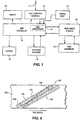
- FIG. 1 is a block diagram illustrating the functionality of a tape drive in accordance with the invention.
- Tape controller 10 manages a plurality of functionally separated blocks, including a host computer interface 12, a tape drive interface 14 which electromechanically cooperates with motors 15 for performing various drive functions, and read/write circuitry 16 which response to commands from the controller 10 to perform reading and writing functions relative to the tape through head assemblies 18. Interaction with the user is through display 20 and manual input 21.
- tape controller 10 is an application specific integrated circuit (ASIC) that includes a microprocessor 13.
- ASIC application specific integrated circuit
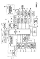
- FIG. 2 is a more detailed block diagram of a tape drive implemented in accordance with one embodiment of the present invention.
- host computer interface 12 is implemented in the form of a Small Computer System Interface (SCSI), which includes a SCSI interface integrated circuit 25 to provide an interface between host interface microcontroller 30 and SCSI bus connector 26.
- SCSI Small Computer System Interface
- Microcontroller 30 provides a control mechanism to support data and command transfers on the SCSI bus 11 according to the standard SCSI interface protocol.
- Microcontroller 30 performs high-level tape control functions via tape controller 10.
- Host interface microcontroller 30 communicates with tape controller 10 over bus 33.
- Program memory 35 stores a control program for host interface microcontroller 30, which is either an electrically erasable and reprogrammable programmable memory (Flash EPROM) or a static random access memory (SRAM).
- Flash EPROM electrically erasable and reprogrammable programmable memory
- SRAM static random access memory
- Head assembly 18 includes the recording and check-after-write (CAW) heads 40. These are four ferrite heads mounted on a rotor assembly 40.
- the recording heads convert the input electrical signals into a magnetic near-field equivalent that is impressed onto the magnetic tape. All four heads are useable to read data from the tape. In read mode, the impressed magnetic field from the tape is converted by the head and output as an equivalent electrical signal.
- the CAW heads are located behind the recording heads and are always used to read data from the tape, but during write mode are used exclusively to verify that the written data is reliably readable.
- Motors 15 include drum motor 44, capstan motor 45, reel motor 46, and load/mode motor 48.
- Drum motor 44 drives the rotating heads assembly 40 that scans the tape surface in a helical pattern.
- Capstan motor 45 drives the capstan, which is responsible for regulating tape speed.
- the capstan motor 45 is bi-directional and can drive the tape in the forward or reverse direction.
- Reel motor 46 drives the supply and take-up reels of the tape cartridge and can likewise drive the tape in either direction.
- the load/mode motor 48 provides power to a mechanical mechanism that loads and unloads the tape cartridge from the tape mechanism. It is also used to select the mode of operation, i.e.: forward, reverse, fast forward and rewind.
- Tape controller 10 controls each of drum motor 44, capstan motor 45, and reel motor 46 via respective 3-phase driver circuits 71, 72, and 73.
- Load/mode motor 48 is controlled by tape controller via motor driver circuit 74.
- Motor drivers 71, 72, 73, 74 are conventional voltage/current translation interfaces that are external to digital ASIC 62.
- Tape drive interface 14 includes sensors for determining the position and status of a tape cartridge in the cartridge mechanism.
- Load/mode motor position sensor 50 provides feedback on the position of the mode control mechanism. This is used by tape controller 10 to control the operation of the mode motor 48.
- Reel tachometers 51 provide speed feedback information for each reel. This is used by tape controller 10 to control reel speed. Reel voltage measurements are monitored and used to control the tape tension between the capstan and takeup reel during forward movement of the tape and between the capstan and supply reel during backward movement of the tape.
- Capstan tachometer 52 can typically be a single-phase tachometer that provides speed information about the capstan. It is used by tape controller 10 to verify proper direction and speed control of the capstan motor 45.
- End-of-tape (EOT) and beginning-of-tape (BOT) indicators are sensed by optical sensors 54 when the transparent tape leader passes in front of those sensors. This information is used by tape controller 10 to stop the reel motor(s) 46 and capstan motor 45.
- Cartridge switches 55 interact with specific locations of the tape cartridge to provide tape controller 10 with information about the tape cartridge such as whether a tape cartridge is inserted in the drive, the type of tape (data vs. cleaning), the length of the tape, and its write protection status.
- Read/write circuitry 16 manages the conversion of digital data from tape controller 10 into analog signals that are appropriate for the recording heads 40 and vice versa. It includes write driver 56 which convert the digital data stream from tape controller 10 into a large enough current to drive the recording heads 40.
- Equalization circuit 59 is a series of filters designed to reduce noise and condition the signal out from the read heads 40.
- An analog application specific integrated circuit (ASIC) 60 is responsible for creating a clock and data stream from the serial data stream received from the read heads 40 after being passed through equalization circuit 59.
- ASIC application specific integrated circuit
- Tape controller 10 interfaces with a host system via SCSI controller 25, and with the tape drive via the tape drive interface 14 and motors 15. Controller 10 employs a digital ASIC 62 for a variety of functions including among others speed and direction control of all motors, data formatting and unformatting, and generation and use of error correction.
- a static random access memory (SRAM) 64 provides a large memory that is used as a data buffer to temporarily store data before being transferred from the host onto tape, or before being transferred from tape to the host.
- Another memory 65 is a relatively small SRAM memory used to store table and error correction redundant terms. It is also used to temporarily buffer small amounts of data from the data stream between the tape controller 10 and the read/write circuitry 16.
- a small, non-volatile random access memory (NVRAM) 66 stores personality information about the drive such as serial number and drive calibration parameters.
- the tape drive in the illustrative embodiment utilizes an 8mm tape cartridge that has tracks recorded thereon in a helical scan pattern. It is, for example, intended to store 33 gigabytes of data with recovery speeds of up to 3 megabytes per second and a 5.25 inch form factor. It relies upon a variable speed architecture wherein servo controls are applied to tape speed and position during read operations.
- the variable speed architecture permits excellent performance under all conditions and reduces wear of heads, mechanisms, and media by eliminating reposition cycles characteristic of streaming tape drives. It is also relatively simple and low cost to design.
- FIG. 3 is a top angular view and FIG. 4 is a side view of the tape path resulting from one arrangement of motors including a reel drive motor 82, capstan motor 83, drum motor 84, and drum 85.
- Drum 85 cooperates with capstan 91 and idler rollers 92 and 93 to retain the tape 80 in an arc of 196 degrees relative to the circumferential periphery of drum 85.
- Capstan 91 is operated by capstan motor 83 so as to modify the position of tape 80 relative to the path of head 96, 97, 98, 99 rotating on drum 85 to maximize the rate at which packets are read from tape 80.
- the relationship between tape position (or track position) and the path of the read/write heads is adjustable to alter the rate at which data is read from the tape.
- data is read over a continuously variable transfer rate of up to a maximum of over 100% of the rate at which data is nominally recorded.
- Pause mode is useful when data over-run or data under-run conditions occur.
- Data is written in tracks in an alternate azimuth, helical pattern by heads 96-99 on drum rotor 85 with an alternate azimuth technique. That is, a pair of alternate azimuth data tracks are recorded simultaneously at an angle across the tape by a pair alternate azimuth adjacent write heads.
- a tape speed servo controller (not shown) maintains the period of drum rotor 85 and speed of tape 80.
- Data is checked half a drum rotation after writing by a pair of alternate azimuth CAW heads located 180 degrees relative to the pair of write heads, and offending tracks re-written "on the fly" as required. Accordingly, for each rotation of drum rotor 85, two tracks are written and a write check of those two tracks is performed.
- the tape speed servo controller maintains the period of drum rotor 85 and speed of tape 80.
- the tape 80 advances a maximum of one track per rotation and error correction is effected after scanning the track with both like-azimuth heads.
- FIG. 5 is a top view of the tape drive configuration of FIGS. 3 and 4, illustrating the path followed by tape 80.
- Tape 80 circulates between supply reel 88 and take-up reel 89 after passing over a series of idler rollers 94a, 94b, 94c, 94d, 94e, and 94f, a biased tension arm and roller 95, and between capstan 91 and pinch roller 92.
- Drum 85 rotates so as to magnetically exchange data between heads 96-99 (see FIG. 3) mounted thereon and tape 80 as it passes over the periphery of the drum 85.
- FIG. 6 is a side view of a portion of a magnetic tape 136 illustrating the angle and position of a pair of typical data tracks 131 and 132 written on it. While only two tracks 131 and 132 are shown, it is understood that many more tracks can precede and/or follow these two examples.
- Each data track 131, 132 is similar and includes a track packet 133, a series of data packets 134, and an error correction packet 135.
- data packets 134 include approximately four hundred packets of data comprising up to sixty-four user bytes of data.
- variable speed architecture of the invention is well suited for high density TPI (tracks per inch) recording. Importantly, no tracking servo is required. This improves the data capacity of the tape cartridge since the portion of the tape traditionally occupied by servo information is made available for data instead. The elimination of the tracking servo also decreases the number components and assemblies of the system, thereby reducing overall cost and lowering power demand. Advantages realized further include operation over a wide range of mechanical component and alignment tolerances. Improved data reliability is obtained under varying conditions of data interchange, temperature, humidity, shock, and vibration.
- FIG. 7(a) A WRITE operation for a variable speed architecture tape drive implemented in accordance with the invention is illustrated in FIG. 7(a).
- the tape speed is plotted against tape position and further correlated with the content of a data buffer 100, such as 64 in FIG. 2, whose various conditions are presented along the upper portion of the plot.
- a data buffer 100 such as 64 in FIG. 2, whose various conditions are presented along the upper portion of the plot.
- buffer 100 When buffer 100 is loaded with data up to the "F" location, this indicates that buffer 100 is full, whereas when the data level is all the way down to the "E" location, this indicates that buffer 100 is empty.
- the proportional buffer contents between those two boundary states are shown by the shaded portion of each buffer.
- FIGS. 7(a) and 7(b) reflect the contents of the buffer 100 at particular points in time.
- buffer 100 attains full status, the tape speed is shifted upwards until full speed is reached. Data draining of buffer 100 results in a slowing of the tape speed whereas detection of a filling buffer 100 results in a shift to a faster tape speed. If buffer 100 is empty, the tape is stopped as at 110 and the Pause Mode is entered. The next WRITE operation received from the host system is started from the paused tape position, but no repositioning of the tape occurs.
- FIG. 7(b) A READ operation for a variable speed architecture tape drive implemented in accordance with the invention is illustrated in FIG. 7(b).
- buffer 100 is shown filling at 111, 112 and 113, with the tape speed approaching a maximum of full speed. From an empty state, maximum acceleration is employed. The tape velocity is reduced as data buffer 100 fills. That is, as data buffer 100 approaches a full state, the tape speed is reduced to prevent data losses.
- the tape is stopped and the Pause Mode is entered as shown at 120. The next read operation is commenced from position 120 without the need for any tape repositioning.
- FIG. 8 is a block diagram of a variable speed architecture tape transport system 300 in accordance with the invention.
- unformatted data 334 is entered into data buffer 302 during write mode and is formatted by data formatter 304.
- the formatted data 332 is recorded onto a magnetic tape by write channel circuitry 306.
- the head widths 317 and head placement 318 are selected to optimize the check after write and overscan performance.
- Adjustable head timing 316 allows the drive to automatically coordinate the time the read heads are activated with the physical position of the data written on the tape.
- Radius calculator 330 continuously calculates the supply and takeup reel radii as tape moves between the supply real and the takeup reel. This calculation is based upon the capstan and reel tachs 331.
- Data is removed from buffer 302 as it is written onto tape, and a data buffer level 303 is adjusted to reflect the current amount of data in the buffer relative to the maximum buffer capacity.
- read channel circuitry 306 recovers formatted data 332 from tape, which is deformatted by deformatter 304 and entered into data buffer 302. Unformatted data 234 is added to buffer 302 as it is read from tape and is removed from buffer 302 as it retrieved for transmission to a host system. Again, the data buffer level 303 is adjusted to reflect the current amount of data in the buffer relative to the maximum buffer capacity.
- Controller 310 monitors the buffer level 303 to determine the appropriate transport speed (or position) of the tape.
- the appropriate speed (or position) of the tape may be different between read mode and write mode for a given buffer level 303, as described in conjunction with FIGS. 7(a) and 7(b). In either mode, however, controller 310 determines whether an adjustment of the current write speed is required based on the current buffer level 303. If the tape speed requires adjusting, controller 310 determines a new tape speed 311 based on the current buffer level 303.
- a head timing controller 314 synchronizes the change in tape speed with the detection of a beginning of a track on the tape. The details of the head timing controller 314 are described hereinafter.
- Tape speed controller 312 changes the speed (or position) of the tape in accordance with the new write speed 311 and a speed change enable signal 315 generated by head timing controller 314.
- Reel tension controller 326 controls the tape tension between the capstan and takeup reel during forward tape movement, as indicated by direction signal 327, and between the capstan and supply reel during backwards tape movement.
- the values of reel amplifier voltage 328 for the correct tensions are stored in non-volatile RAM 66.
- the reel tension controller 326 When running, the reel tension controller 326 outputs a pulse width modulation (PWM) signal to the reel amplifier 72.
- PWM pulse width modulation
- FIG. 19 An illustrative embodiment of the method implemented by reel tension controller 326 is illustrated in FIG. 19.
- the reel motor voltage is updated to provide the correct tape tension between the capstan and reel every 8 msec.
- radius calculator 330 determines whether enough tape motion has occurred, based on the change in reel and capstan tachs 331, to justify a new radius calculation. If so, radius calculator 330 calculates the new radii 329 for the supply reel and takeup reel in step 504. The new radii 329 and the tension constants stored in NVRAM 66 corresponding to the current direction 327, which are stored in step 506, are used by reel tension controller 326 for calculating a reel motor voltage corresponding to the correct tape tension between the capstan and reel in step 508.
- the newly calculated reel motor voltage is applied to the reel motor to adjust the tension between the capstan and reel every millisecond. This is accomplished by performing the steps of measuring the reel amplifier output voltage in step 512, comparing the measured amplifier voltage with the calculated voltage in step 514 which provides the correct tape tension, and adjusting the input signal to the reel amplifier in step 516 to obtain the correct output voltage.
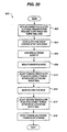
- FIG. 20 is a flowchart of the calibration method used by reel tension controller.
- a step 602 the minimum voltage required to spin the takeup and supply reel hubs with the tape mechanism fully ejected is determined. These offset measurements are stored in non-volatile RAM 66 in step 604.
- a special "golden standard" torque tape cassette is loaded into the drive in step 606.
- the drive begins playing the special torque cassette in forward play mode in step 608.
- the forward tension slope is adjusted to achieve the correct tension between the capstan and takeup reel in a step 610.
- the drive then plays the special torque cassette in reverse play mode in step 612.
- the reverse tension slope is adjusted to achieve the correct tension between the capstan and supply reel in a step 614.
- the forward and reverse tension slopes are stored in non-volatile RAM 66 in step 616.
- This system maintains the correct tension as the radii vary and as the drive temperature or power supply voltages fluctuate.
- other tape devices have used active tension sensors and dual reel motors or slip clutches in the supply and takeup hubs.
- the active tension sensors and dual reel motors added significant cost and complexity to the tape drive.
- the slip clutches provided inconsistent tension from unit to unit and over the life of the tape drive.
- the position on tape as indicated by tapecount 321 is calculated by physical position identifier 322 using the reel tachs 324.
- the tapecount 321 is defined as the sum of the supply reel and takeup reel tachs. As tape moves from the supply reel to the takeup reel, the count value increases. As tape moves from the takeup reel onto the supply reel, the count value decreases. Tapecount 321 is set to zero at the beginning of tape.
- Highspeed tape repositioning is accomplished with tape position controller 320.
- the reel motor is used to reposition the tape to a target position 325 provided by the read/write controller 310.
- FIG. 9 is a flowchart of a method to prevent writing thin tracks.
- the track spacing error is calculated every predetermined interval (e.g., 1 msec) in step 500.
- a reference position is calculated based upon the desired tape speed in step 501.
- the current tape spacing is inferred from the measured capstan tach 502.
- step 504 If the track spacing is too large, as determined in step 504, it means that the tape has moved too quickly. If the spacing is too small, the tape has moved too slowly. The natural response is to slow down when the tape is moving too quickly. To avoid this, when the position is further than the target 505, the reference position is set in step 505 to the measured position. The new position error is then set to zero in step 506. The position error is used in step 507 by the read/write controller 310 as one parameter for determining the new read/write speed 311.
- FIG. 10 is a timing diagram illustrating the synchronization of the write head position relative to tracks on the tape with a change in tape speed, as performed by head timing controller 314.
- head timing controller 314 receives a head type signal WRITE_HEAD that is logically high when the two recording, or "write", heads are positioned over the tape and logically low when the two CAW heads are positioned over the tape.
- Head timing controller 314 generates a SYNC pulse a predetermined time )(t1) after the rising edge of WRITE_HEAD. This triggers the output of speed change enable signal 315 SPEED_CHANGE_EN pulse a predetermined time )(t2) later, during the phase in which the read heads are positioned over the tape.
- Tape speed controller 312 adjusts the speed (or position) of the tape to the new speed 311 in synchronization with the SPEED_CHANGE_EN 315 pulse.
- the allowable difference in adjusted speed is limited to that which results in the final desired speed being achieved within the phase )(t3) in which the read head is over the tape. This ensures that the tape is moving at a constant speed during the time the track is being recorded (i.e., while the write heads are over the track) such that unintentional track curvature does not result.
- FIG. 10 illustrates an example of the actual tape velocity for a deceleration example, labeled TAPE_VELOCITY_1, and an acceleration example, labeled TAPE_VELOCITY_2.
- the actual initial speed and actual final speed may represent different values anywhere between the maximum and minimum speeds in order to accommodate various speed change trajectories.
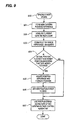
- FIG. 11 is a flowchart of the method employed by the variable speed architecture of the tape drive while it is in write mode.
- variable speed recording is begun in step 400 when the drive enters write mode.
- An initial tape speed is selected in step 402 based on the amount of data present in the data buffer 302.
- the data formatter 304 is configured in step 404 to write a predetermined number of dummy tracks before changing speed.
- the head timing controller 314 is configured for a speed change in step 406.
- the dummy tracks are poised to be written to tape via the write channel circuitry 306 in step 408.
- head timing controller 314 monitors the position of the heads in step 410, generating speed change enable signal SPEED_CHANGE_EN in synchronization with the beginning of the phase in which the read heads are positioned over the tape.
- Tape speed controller 312 changes the speed of the tape to the new speed in step 412.
- data formatter 304 is configured to write a programmable number of data tracks in step 414, which are written to tape the next time the write heads are positioned over the track in step 416, followed by writing actual data tracks in step 418 containing data (formatted into data tracks) from the buffer 302.
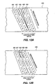
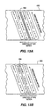
- FIGS. 12(a) and 12(b) illustrate recorded track angle changes resulting from a respective deceleration and acceleration in tape speed.
- a predetermined number of dummy track pairs 482 is first written to tape at the current speed. The speed is decreased while the read heads are over the track.
- a predetermined number of dummy track pairs 483 followed by more data track pairs 484 are written to the tape at the new slower speed. As shown, this results in a "residue" zone 485 on tape 480 wherein data is indeterminate.
- the residue zone 485 does not affect the reliability of any data written onto the tape, however, since no data tracks overlap.
- a predetermined number of dummy track pairs 487 are first written to tape at the current speed.
- the speed is increased while the read heads are over the track.
- a predetermined number of dummy track pairs 488 followed by more data track pairs 489 are written to the tape at the new faster speed.
- this results in an overlap zone 490 between dummy track pair 487 and dummy track pairs 488.
- the overlap zone 490 does not affect the reliability of any data written onto the tape, however, since it occurs only between dummy track pairs 488 and 489.
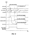
- FIG. 14 is a timing diagram illustrating the detection of speed errors encountered during the read-back-check of the data by the tape speed controller 312 while the drive is in write mode.
- the capstan signal WRITE_HEAD indicates the position of the write head over the tape.
- a maximum speed threshold and minimum speed threshold are programmable and set to values which, if respectively exceeded or not met, could possibly lead to a residue zone or overlap region regardless of the type of track being written. This is undesirable if the tracks being written are actual data tracks.
- TAPE_VELOCITY if the tape speed TAPE_VELOCITY does not remain between the thresholds MAX_SPEED and MIN_SPEED, a respective threshold violation signal OVER_MAX_SPEED or UNDER_MIN_SPEED is asserted, which results in the assertion of check-after-write fail signal FAILED_CAW 313.
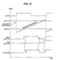
- FIG. 15 illustrates the response of tape speed controller 312 to a violation of a position control failure.
- a measure of the track spacing is taken and compared to a programmable maximum spacing threshold MAX_PITCH and minimum spacing threshold MIN_PITCH. If the measured track pitch is below the minimum spacing threshold MIN_PITCH, error signal UNDER_MIN_PITCH is signaled; if the measured track pitch is beyond the maximum spacing threshold MAX_PITCH, error signal OVER_MAX_PITCH is signaled.
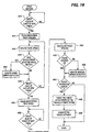
- FIG. 16 is a flowchart of the method used by tape speed controller 312 to detect conditions for rewriting a track.
- the capstan tachometer signal WRITE_HEAD is monitored in step 442 until it indicates that the write heads are positioned at the beginning of a new track. Once the write heads are positioned over a new track, the drive begins to measure the track pitch in step 444.
- the tape speed is monitored in step 446 and compared in step 448 to the maximum and minimum speed thresholds MAX_SPEED and MIN_SPEED as shown in FIG. 14 to detect any threshold violations. If a threshold violation is detected the particular speed threshold violation is denoted in step 450.
- step 452 the position of the tape is checked to determine whether the write heads have reached the end of the new track. If not, steps 446, 448, and 450 (if appropriate) are repeated. Once the write heads have reached the end of the new track in step 454, the tape speed signal is no longer monitored. The position of the write heads is continuously monitored in step 456 until the beginning of the next track is detected, at which time the track pitch is calculated in step 458.
- the track pitch is compared in step 460 to the maximum and minimum allowed track pitches MAX_PITCH and MIN_PITCH to detect any pitch threshold violations. If a track pitch threshold violation is detected, the particular position threshold violation is denoted in step 462. If a speed or position threshold violation as determined to have occurred during step 464, the check-after-write fail signal FAILED_CAW is asserted in step 466 to indicate that the check-after-write of the previous track failed. The previous track is then rewritten in step 468.
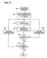
- FIG. 17 is a flowchart illustrating the method employed by the variable speed architecture of the tape drive while it is in read mode.
- variable speed reading is begun in step 420 when the drive enters read mode.
- An initial tape speed is selected in step 422 according to the amount of data present in the data buffer 302.
- the head timing controller 314 is configured for a speed change in step 424.
- Head timing controller 314 monitors the position of the heads in step 410, generating speed change enable signal SPEED_CHANGE_EN in synchronization with read heads positioned over the tape. This triggers tape speed controller 312 to change the speed of the tape to the new speed.
- Read channel circuitry 306 reads data from the tape, which is deformatted by deformatter 304 and put into data buffer 322 in step 426.
- the buffer level 303 indicating the current amount of data in buffer 322 relative to its maximum capacity is monitored in step 428. If the buffer level 303 indicates that data buffer 302 is nearly full (relative to a predetermined threshold), controller 310 calculates a slower read speed in step 430, and steps 424, 426, and 428 are repeated. If the buffer level 303 indicates that data buffer 302 is nearly empty (relative to a predetermined threshold) in step 432, controller 310 calculates a faster read speed in step 434 and steps 424 - 428 are repeated. If the buffer level appears to remain steady (indicating that the data transfer rate is sustained at a streaming rate), no adjustment in speed is made.
- each buffer level threshold may be set at any level between those representing a full and empty buffer, preferably at levels determined to optimize the matching of the tape speed to that of the host system.
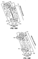
- FIGS. 18(a) and 18(b) illustrate how data is read from a tape having track angle changes resulting from a respective deceleration and acceleration in tape speed.
- the tape 480 contains a residue zone 475 resulting from a deceleration in tape speed during write mode, as shown in FIG. 18(a)
- portions of opposite-azimuth dummy track pairs 471 and 472 are read first by leading write head A and then by trailing write head B one revolution of the drum later. If the angle of the heads with respect to the tracks 471-474 do not match, any given head A or B will not read an entire track during a first pass. Instead, as illustrated in the example of FIG.
- any A-azimuth data from dummy track 471 is not read by head A and any A-azimuth data from dummy track 472 is not read by head B due to the opposite azimuths of the tracks and the ability of the heads to detect data written along the appropriate azimuth.
- head A is completely aligned over dummy B-azimuth track 473 and head B is completely aligned over dummy A-azimuth track 474, and hence neither head A nor B detect any data.
- head A is positioned over a portion of dummy A-azimuth track 474 and a portion of dummy B-azimuth track 473, and hence detects only A-azimuth data from track 474 indicating that it is a dummy track.
- Head B is positioned over a portion of dummy B-azimuth track 473, a portion of residue zone 475, and a portion of dummy A-azimuth track 472, and hence detects any B-azimuth data from track 473 indicating that it is a dummy track, and any old B-azimuth data present in residue zone 475 left over from a previous recording.
- Data formatter 304 must therefore keep track of, and discard, any detected data found between two adjacent dummy tracks.
- the use of dummy tracks again ensures reliable data recovery as follows. Portions of opposite-azimuth dummy track pairs are read first by leading write head A and then by trailing write head B one revolution of the drum later. If the angle of the heads with respect to the tracks 476-479 do not match, any given head A or B will not read an entire track during a first pass. Instead, as illustrated in the example of FIG. 18(b), at position P4 leading head A can read portions of dummy A-azimuth track 477 and dummy A-azimuth track 479, while trailing head B can read portions of dummy B-azimuth track 476.
- any A-azimuth data from dummy track 478 is not read by head A and any A-azimuth data from dummy track 477 is not read by head B due to the opposite azimuths of the tracks.
- head A is completely aligned over dummy A-azimuth track 479 and head B is completely aligned over dummy A-azimuth track 478, and hence heads A and B both detect correct data.
- head A is positioned over a portion of dummy A-azimuth track 479, and hence detects A-azimuth data from track 479 indicating that it is a dummy track.
- Head B is positioned over a portion of dummy A-azimuth track 479, a portion of dummy B-azimuth track 478, and a portion of dummy A-azimuth track 477, and hence detects only B-azimuth data from track 478 indicating that it is a dummy track. Accordingly, because all detected data during this portion of the tape is a dummy track of one azimuth or the other, and hence not entered into the data buffer, the use of dummy tracks immediately before and after changing tape speeds during write mode eliminates any data recovery problems when the same portion of the tape is read during read mode.
- variable speed control in combination with the ready mode, dramatically boost performance during read and write operations, when the host system cannot achieve or maintain the tape drive's rated throughput.
- the variable speed architecture produces a match of the average data transfer rate of a host computer and eliminates tape repositioning cycles.
- the read data rate is continuously variable.
- the architecture of the invention operates to slow the tape speed to enhance read accuracy. This is particularly valuable when interchanging data tapes amongst similar tape drives. Accordingly, back up and restore times are accelerated through the elimination of backhitching.
Abstract
Description
In accordance with the invention, the speed of the tape is adjusted according to both the level of data present in the tape drive data buffer and whether the current mode of the drive is write mode or read mode. In the preferred embodiment, when the tape speed is accelerated or decelerated while writing a number of data track pairs to tape, a predetermined number of dummy track pairs are first written to tape at the current speed. On the next write head phase after the speed is increased or decreased as appropriate while the read heads are over the track, a predetermined number of dummy track pairs followed by more data track pairs are written to the tape at the new speed. Any resulting previously recorded track residue zones or overlap zones do not affect the reliability of any data written onto the tape since they occur between dummy track pairs, a detectable condition in read mode.
FIG. 16 is a flowchart of the method used by
Claims (11)
- A method for recording data at variable speeds onto a magnetic tape (480) with a variable speed magnetic recording and reproducing apparatus which tape is being transported across a rotating drum (85) at a current tape transport speed, said rotating drum having a recording head (96, 97, 98, 99) disposed thereon to pass over said tape upon rotation of said drum, said data being received from a host system (12) and temporarily stored in a data buffer (64), said method comprising:wherein said current tape transport speed and said new tape transport speed are each non-zero.monitoring (402) a current buffer level (303) of said data buffer, said current buffer level indicating an amount of data currently present in said data buffer;determining (402) a new tape transport speed based on said current buffer level;writing (404) a first predetermined number of dummy tracks (482, 487) onto said magnetic tape at said current tape transport speed;adjusting (412) said current tape transport speed to said new tape transport speed; andwriting (414/416) a second predetermined number of dummy tracks (483, 488) onto said magnetic tape at said new tape transport speed immediately after said first predetermined number of dummy tracks;
- A method in accordance with claim 1, comprising:recording (418) a second data track (484, 489) onto said magnetic tape at said new tape transport speed immediately after said second predetermined number of dummy tracks.
- A method in accordance with claim 1 or 2, comprising:recording a first data track (481, 486) onto said magnetic tape at said current tape transport speed immediately before said first predetermined number of dummy tracks.
- A method in accordance with claim 1, 2 or 3, wherein said new tape transport speed is slower than said current tape transport speed.
- A method in accordance with claim 1, 2 or 3, wherein:said new tape transport speed is faster than said current tape transport speed.
- A method in accordance with claim 2, 3, 4, or 5 comprising:measuring (446) said current tape transport speed;determining (448) whether said current tape transport speed is outside a speed control limit; andif said current tape transport speed is outside said speed control limit, performing the steps of:setting said new tape transport speed to a speed within said speed control limit :adjusting said current tape transport speed to said new tape transport speed; andre-recording (468) said second data track onto said magnetic tape at said new tape transport speed.
- A method in accordance with claim 2, 3, 4, 5, or 6, comprising:measuring (444, 458) a track pitch, said track pitch comprising the distance between said recorded track and an immediately-previous previously-recorded track;determining (460) whether said track pitch is outside a track pitch control limit; andif said track pitch is outside said track pitch control limit, performing the steps of:setting (505) said new tape transport speed to a speed that will place a next measured track pitch within said track pitch control limit ;adjusting (507) said current tape transport speed to said new tape transport speed; andre-recording (468) said second data track onto said magnetic tape at said new tape transport speed.
- A method in accordance with claim 1, 2, 3, 4, 5, 6, or 7, wherein:said adjusting step comprises:commencing said speed adjustment when said rotating drum is positioned such that said recording head is not positioned over said tape; andcompleting said speed adjustment before said recording head becomes positioned over said tape.
- A method in accordance with claim 2, 3, 4, 5, 6, 7, or 8, comprising:reading back said recorded second data track at said new tape transport speed Immediately after said recorded second data track is recorded onto said magnetic tape.
- A method in accordance with claim 12, comprising:re-recording (468) said second data track if said recorded second data track is unreadable.
- A method in accordance with claim 1, comprising:reading a track from said magnetic tape at said new speed.
Applications Claiming Priority (3)
| Application Number | Priority Date | Filing Date | Title |
|---|---|---|---|
| US176079 | 1988-03-30 | ||
| US09/176,079 US6307701B1 (en) | 1998-10-20 | 1998-10-20 | Variable speed recording method and apparatus for a magnetic tape drive |
| PCT/US1999/024652 WO2000023992A2 (en) | 1998-10-20 | 1999-10-20 | Variable speed recording method and apparatus for a magnetic tape drive |
Publications (3)
| Publication Number | Publication Date |
|---|---|
| EP1145235A2 EP1145235A2 (en) | 2001-10-17 |
| EP1145235A3 EP1145235A3 (en) | 2001-10-31 |
| EP1145235B1 true EP1145235B1 (en) | 2002-12-18 |
Family
ID=22642888
Family Applications (1)
| Application Number | Title | Priority Date | Filing Date |
|---|---|---|---|
| EP99955108A Expired - Lifetime EP1145235B1 (en) | 1998-10-20 | 1999-10-20 | Variable speed recording method for a magnetic tape drive |
Country Status (7)
| Country | Link |
|---|---|
| US (3) | US6307701B1 (en) |
| EP (1) | EP1145235B1 (en) |
| JP (1) | JP2002528835A (en) |
| AT (1) | ATE230149T1 (en) |
| AU (1) | AU1128700A (en) |
| DE (1) | DE69904649T2 (en) |
| WO (1) | WO2000023992A2 (en) |
Families Citing this family (34)
| Publication number | Priority date | Publication date | Assignee | Title |
|---|---|---|---|---|
| WO2001039496A1 (en) * | 1999-11-22 | 2001-05-31 | Sony Corporation | Videotape recording and playback device, and videotape player |
| US20030123174A1 (en) * | 2001-12-28 | 2003-07-03 | Mark Hennecken | Continuously variable storage device data transfer rate |
| US6856479B2 (en) | 2002-01-29 | 2005-02-15 | International Business Machines Corporation | Writing synchronized data to magnetic tape |
| US7162574B2 (en) * | 2003-04-22 | 2007-01-09 | International Business Machines Corporation | Transaction-based data storage for magnetic tape |
| US7127576B1 (en) * | 2003-05-21 | 2006-10-24 | Raytheon Company | Method and system for data duplication |
| US7236322B2 (en) | 2003-08-20 | 2007-06-26 | International Business Machines Corporation | Method, system, and program for storing data in a storage medium |
| US6958878B2 (en) * | 2003-10-27 | 2005-10-25 | International Business Machines Corporation | Forced backhitch for speed matching in a multi-speed tape drive |
| US7535664B1 (en) * | 2003-11-13 | 2009-05-19 | Storage Technology Corporation | Performance enhancement for tape write immediate operations |
| US7206873B1 (en) * | 2003-11-13 | 2007-04-17 | Storage Technology Corporation | Throughput optimization by activation of selected parallel channels in a multichannel tape drive |
| TW200527401A (en) * | 2004-02-10 | 2005-08-16 | Signal Electronic Co Ltd | A data storage protection method and device thereof |
| US6950257B1 (en) | 2004-04-29 | 2005-09-27 | International Business Machines Corporation | Writing to magnetic tape with backhitchless backspacing and data set invalidation |
| US6956709B1 (en) | 2004-06-07 | 2005-10-18 | Storage Technology Corporation | Write velocity identification in a PRML system |
| US7023651B1 (en) * | 2004-07-14 | 2006-04-04 | Storage Technology Corporation | Reduction of tape velocity change backhitch time through use of an intermediate back velocity |
| US7154695B2 (en) * | 2004-11-10 | 2006-12-26 | Certance, Llc | System and method for controlling the speed of a tape drive |
| US7190544B2 (en) * | 2004-11-10 | 2007-03-13 | Certance Llc | System and method for tape drive under run control |
| US7433141B2 (en) * | 2005-03-09 | 2008-10-07 | Tandberg Data Corporation | Data randomization for rewriting in recording/reproduction apparatus |
| US20060204209A1 (en) * | 2005-03-09 | 2006-09-14 | Exabyte Corporation | Pause strategy for magnetic tape recording |
| JP4140913B2 (en) * | 2005-05-12 | 2008-08-27 | インターナショナル・ビジネス・マシーンズ・コーポレーション | Apparatus, method, and program for controlling drive of recording medium |
| US7793159B2 (en) * | 2006-10-02 | 2010-09-07 | International Business Machines Corporation | Method, computer program product, and computer system for detecting a corruption in a data block stored by a tape recording apparatus |
| JP2008269700A (en) * | 2007-04-19 | 2008-11-06 | Fujitsu Ltd | Tape management program, tape management device and tape management method |
| US8190834B2 (en) * | 2007-06-15 | 2012-05-29 | Emc Corporation | Process for contiguously streaming data from a content addressed storage system |
| US8626741B2 (en) * | 2007-06-15 | 2014-01-07 | Emc Corporation | Process for cataloging data objects backed up from a content addressed storage system |
| US20090125649A1 (en) * | 2007-11-14 | 2009-05-14 | Turguy Goker | Variable speed buffer servo control for linear tape drives |
| JP4954141B2 (en) * | 2008-05-30 | 2012-06-13 | インターナショナル・ビジネス・マシーンズ・コーポレーション | Apparatus and method for controlling running of tape medium |
| WO2010004936A1 (en) * | 2008-07-08 | 2010-01-14 | インターナショナル・ビジネス・マシーンズ・コーポレーション | Device for adjusting traveling speed of tape medium, method for adjusting traveling speed, and program for adjusting traveling speed |
| JP4866412B2 (en) * | 2008-10-10 | 2012-02-01 | インターナショナル・ビジネス・マシーンズ・コーポレーション | Tape drive capable of selecting optimum tape speed for intermittent reading requests, tape drive recording system, and method for selecting optimum tape speed |
| US7995303B2 (en) * | 2009-08-31 | 2011-08-09 | International Business Machines Corporation | Overhead calculation in writing synchronized data to magnetic tape |
| WO2011058794A1 (en) * | 2009-11-13 | 2011-05-19 | インターナショナル・ビジネス・マシーンズ・コーポレーション | Device and method for controlling writing of data |
| EP2512963B1 (en) | 2009-12-18 | 2015-10-21 | Pirelli Tyre S.p.A. | Method and apparatus for controlling the winding of an elongated element onto a collection reel with the interposition of a service fabric |
| US8023215B1 (en) * | 2010-05-25 | 2011-09-20 | Seagate Technology Llc | Data recovery scan based on head performance |
| JP2014022002A (en) | 2012-07-17 | 2014-02-03 | International Business Maschines Corporation | Recording device for recording data sequentially and tape speed alteration method therefor |
| JP5939582B2 (en) | 2013-08-22 | 2016-06-22 | インターナショナル・ビジネス・マシーンズ・コーポレーションInternational Business Machines Corporation | Reduction of tape drive buffer power consumption |
| US10685676B1 (en) | 2019-06-04 | 2020-06-16 | International Business Machines Corporation | Adaptive tension position change on tape drive |
| US10770107B1 (en) * | 2019-06-04 | 2020-09-08 | International Business Machines Corporation | Adaptive tension position changing for magnetic tape recording device |
Family Cites Families (106)
| Publication number | Priority date | Publication date | Assignee | Title |
|---|---|---|---|---|
| US3821710A (en) | 1972-12-04 | 1974-06-28 | Little Inc A | Multimode search and retrieval tape system |
| JPS5736656B2 (en) | 1973-11-20 | 1982-08-05 | ||
| US4011587A (en) | 1974-03-14 | 1977-03-08 | International Business Machines Corporation | Rotary head magnetic recorder for use with a specific record member |
| US4106065A (en) | 1976-03-19 | 1978-08-08 | Ampex Corporation | Drive circuitry for controlling movable video head |
| US4175267A (en) | 1976-07-30 | 1979-11-20 | Sony Corporation | Method and apparatus of inserting an address signal in a video signal |
| US4099211A (en) | 1976-09-13 | 1978-07-04 | Ampex Corporation | Positionable transducing mounting structure and driving system therefor |
| US4125881A (en) | 1977-05-19 | 1978-11-14 | International Business Machines Corporation | Tape motion control for reel-to-reel drive |
| JPS5492308A (en) | 1977-12-29 | 1979-07-21 | Sony Corp | Head tracking device in recorder-reproducer |
| DE2841728C2 (en) | 1978-09-26 | 1984-08-09 | Robert Bosch Gmbh, 7000 Stuttgart | Method and circuit arrangement for reproducing a video signal stored on magnetic tape at variable speed |
| US4215377A (en) | 1978-10-10 | 1980-07-29 | Norris Elwood G | Multi-speed tape cassette system |
| DE2906836A1 (en) | 1979-02-22 | 1980-09-04 | Blaupunkt Werke Gmbh | Tape recorder recorded position indication - has sub-audio code signals recorded onto tape for higher frequency replay during fast forward wind rewind |
| US4257075A (en) | 1979-03-23 | 1981-03-17 | Minnesota Mining And Manufacturing Company | Tape magazine and recording and/or playback machine with improved magazine locating and loading structure |
| AU536904B2 (en) | 1979-06-06 | 1984-05-31 | Sony Corporation | Magnetic tape loading apparatus |
| AU540275B2 (en) | 1979-09-27 | 1984-11-08 | Sony Corporation | V.t.r. synchronizing system |
| JPS5683808A (en) | 1979-12-11 | 1981-07-08 | Sony Corp | Magnetic recording and reproducing device |
| JPS5693157A (en) | 1979-12-26 | 1981-07-28 | Hitachi Ltd | Tape sound recorder |
| JPS56156924A (en) | 1980-05-08 | 1981-12-03 | Sony Corp | Track following device |
| JPS5727421A (en) | 1980-07-23 | 1982-02-13 | Sony Corp | Track following device |
| JPS5733417A (en) | 1980-07-31 | 1982-02-23 | Fujitsu Ltd | Step feed controlling system of information medium |
| JPS5755579A (en) | 1980-09-19 | 1982-04-02 | Sharp Corp | Recorder and reproducer |
| US4467373A (en) | 1980-10-09 | 1984-08-21 | Micro Consultants Limited | Storage and retrieval of digital data on video tape recorders |
| JPS5783978A (en) | 1980-11-12 | 1982-05-26 | Sony Corp | Video signal recorder and reproducer |
| JPS5786161A (en) | 1980-11-17 | 1982-05-29 | Sony Corp | Tape loading device |
| US4412260A (en) | 1981-04-24 | 1983-10-25 | Magnetic Peripherals Inc. | Cartridge receiver mechanism |
| JPS57203228A (en) | 1981-06-09 | 1982-12-13 | Sony Corp | Tracking adjuster |
| JPS57205845A (en) | 1981-06-10 | 1982-12-17 | Nippon Columbia Co Ltd | Recording and reproducing device for digiral signal data |
| GB2111288B (en) | 1981-11-20 | 1985-04-11 | Sony Corp | Magnetic tape recording and reproducing arrangements |
| JPS58133665A (en) | 1982-02-04 | 1983-08-09 | Pioneer Video Corp | Reproduction end detector in information reproducer |
| US4544967A (en) | 1982-04-02 | 1985-10-01 | Ampex Corporation | Automatic scan tracking servo system |
| JPS58185009A (en) | 1982-04-23 | 1983-10-28 | Sony Corp | Magnetic recording and reproducer |
| JPS58194480A (en) | 1982-05-07 | 1983-11-12 | Matsushita Electric Ind Co Ltd | Magnetic video recording and reproducing device |
| JPS5937783A (en) | 1982-08-25 | 1984-03-01 | Sony Corp | Recording device for video signal |
| JPS59112406A (en) | 1982-12-17 | 1984-06-28 | Sony Corp | Recording and reproducing method of pcm signal |
| US4628383A (en) | 1983-01-28 | 1986-12-09 | Victor Company Of Japan, Ltd. | Tape cassette loading device in a magnetic recording and/or reproducing apparatus |
| US4642714A (en) | 1983-02-08 | 1987-02-10 | Victor Company Of Japan, Ltd. | Tape cassette loading and ejecting device in a magnetic recording and/or reproducing apparatus |
| US4637023A (en) | 1983-02-14 | 1987-01-13 | Prime Computer, Inc. | Digital data error correction method and apparatus |
| JPS59151348A (en) | 1983-02-16 | 1984-08-29 | Sanyo Electric Co Ltd | Recording mode discriminating circuit |
| JPS59157810A (en) | 1983-02-28 | 1984-09-07 | Sony Corp | Recording and reproducing method of pcm signal |
| JPS59185019A (en) | 1983-04-04 | 1984-10-20 | Nec Corp | Special reproducer |
| JPS59213057A (en) | 1983-05-16 | 1984-12-01 | Sony Corp | Tape loading device |
| JPS6025062A (en) | 1983-07-21 | 1985-02-07 | Sony Corp | Recording method of address signal |
| JPS6032110A (en) | 1983-08-03 | 1985-02-19 | Victor Co Of Japan Ltd | Head position controller |
| EP0137311B1 (en) | 1983-09-08 | 1988-12-14 | Fuji Photo Film Co., Ltd. | Device for loading or unloading magnetic disc pack |
| US4641210A (en) | 1983-09-24 | 1987-02-03 | Sony Corporation | Magnetic recording and reproducing apparatus |
| JPS6064441U (en) | 1983-10-05 | 1985-05-07 | 日本ビクター株式会社 | Tape storage case insertion lid lock mechanism |
| JPS60197969A (en) | 1984-03-19 | 1985-10-07 | Sanyo Electric Co Ltd | Tape speed discriminating circuit |
| US4554598A (en) | 1984-05-25 | 1985-11-19 | Honeywell Information Systems, Inc. | Single revolution disk sector formatter |
| JPS60194793U (en) | 1984-06-01 | 1985-12-25 | ソニー株式会社 | cassette tape recorder |
| JPH0687330B2 (en) | 1984-08-06 | 1994-11-02 | ソニー株式会社 | Digital signal playback device |
| JPS6166250A (en) | 1984-09-07 | 1986-04-05 | Sony Corp | Tracking control circuit |
| AT382475B (en) | 1984-11-15 | 1987-02-25 | Philips Nv | RECORDING AND / OR PLAYING DEVICE |
| JPS61187103A (en) | 1985-02-14 | 1986-08-20 | Sony Corp | Device for recording and reproducing audio signal |
| JPS61196422A (en) | 1985-02-25 | 1986-08-30 | Sony Corp | Recording device for video signal |
| EP0193153B1 (en) | 1985-02-25 | 1991-11-13 | Matsushita Electric Industrial Co., Ltd. | Digital data recording and reproducing method |
| JPH0792958B2 (en) | 1985-05-27 | 1995-10-09 | ソニー株式会社 | Cassette type recording / reproducing device |
| JPS629552A (en) | 1985-07-08 | 1987-01-17 | Canon Inc | Signal reproducing device |
| JP2606186B2 (en) | 1985-07-09 | 1997-04-30 | ソニー株式会社 | Recording and playback device |
| US4935824A (en) | 1985-07-19 | 1990-06-19 | Sony Corporation | Information recording apparatus |
| JPS6252752A (en) | 1985-08-30 | 1987-03-07 | Sony Corp | Recording and reproducing device |
| JPH0664893B2 (en) | 1985-11-12 | 1994-08-22 | ソニー株式会社 | Magnetic tape recording / reproducing device |
| JPS62140203A (en) | 1985-12-13 | 1987-06-23 | Pioneer Electronic Corp | Rotating head type digital signal reproducing device |
| JPH07107782B2 (en) | 1986-02-28 | 1995-11-15 | ソニー株式会社 | Digital tape recorder |
| EP0235782B1 (en) | 1986-03-04 | 1992-01-22 | Sony Corporation | Apparatus for reproducing a digital signal |
| JP2751150B2 (en) | 1986-03-11 | 1998-05-18 | ソニー株式会社 | Magnetic tape recording device and reproducing device |
| US4897739A (en) | 1986-04-07 | 1990-01-30 | Canon Kabushiki Kaisha | Multi-channel recording apparatus using a plurality of heads in turn |
| US4717974A (en) | 1986-05-19 | 1988-01-05 | Eastman Kodak Company | Waveguide apparatus for coupling a high data rate signal to and from a rotary head scanner |
| NL8602820A (en) * | 1986-11-07 | 1988-06-01 | Philips Nv | METHOD FOR ADJUSTING A MAGNETIC HEAD OF A MAGNETIC BAND APPARATUS AND MAGNET BAND APPARATUS, CARRYING OUT THIS METHOD |
| US4821129A (en) | 1986-11-21 | 1989-04-11 | Hewlett-Packard Company | Tape positioning using reverse boundary capture: tape drive system and method |
| KR970008628B1 (en) | 1986-12-26 | 1997-05-27 | 소니 가부시키사이샤 | Magnetic tape driving device |
| US4769811A (en) | 1986-12-31 | 1988-09-06 | American Telephone And Telegraph Company, At&T Bell Laboratories | Packet switching system arranged for congestion control |
| US4947272A (en) | 1987-03-30 | 1990-08-07 | Pioneer Electronic Corporation | Signal reproducing device which offsets the tracking error signal for a digital tape player |
| US4843495A (en) | 1987-05-11 | 1989-06-27 | Exabyte Corporation | Cyclical servo zone tracking method and apparatus for helical scan recording devices |
| US4845577A (en) | 1987-05-11 | 1989-07-04 | Exabyte Corporation | Apparatus and method for enabling rapid searching of helically recorded magnetic tape |
| US4835628A (en) | 1987-05-11 | 1989-05-30 | Exabyte Corporation | Apparatus and method for formatting and recording digital data on magnetic tape |
| US5115500A (en) | 1988-01-11 | 1992-05-19 | International Business Machines Corporation | Plural incompatible instruction format decode method and apparatus |
| US5003411A (en) | 1988-02-26 | 1991-03-26 | Pioneer Electronic Corporation | Method for recording/reproducing and searching digital signals using a helical scan type rotary head |
| NL8800856A (en) | 1988-04-05 | 1989-11-01 | Philips Nv | MAGNETIC TAPE EQUIPMENT FITTED WITH A CONTROL UNIT FOR CONTROLLING BANDBUFFERS, TIRE PRESSURE AND TIRE TRANSPORT. |
| US4933784A (en) | 1988-10-31 | 1990-06-12 | Ampex Corporation | Automatic head position tracking system for video signals recorded in a segmented format |
| US4935827A (en) | 1988-11-09 | 1990-06-19 | Ampex Corporation | Dynamic head position tracking control for a magnetic tape playback system |
| US4930027A (en) | 1988-11-23 | 1990-05-29 | Ampex Corporation | Method and apparatus for tape speed override operation when recovering helical audio |
| JP2732884B2 (en) * | 1989-03-15 | 1998-03-30 | シャープ株式会社 | Data recording method, data reproducing method, data recording / reproducing method, recording device, reproducing device, and recording / reproducing device |
| US5103355A (en) | 1989-04-11 | 1992-04-07 | Ampex Corporation | System for correlating head scan tracking and tape timer transitions |
| US5274772A (en) | 1989-06-28 | 1993-12-28 | International Business Machines Corporation | Data processing systems having means for selectively combining records into signal blocks for recording in a record medium |
| US5068757A (en) | 1989-11-09 | 1991-11-26 | Exabyte Corporation | Servo tracking for helical scan recorder |
| US5034833A (en) | 1989-11-09 | 1991-07-23 | Exabyte Corporation | Method and apparatus for loading data cartridge about two pivot axes into cartridge drive |
| US5142422A (en) | 1989-11-09 | 1992-08-25 | Exabyte Corporation | Dual channel helical recorder |
| JP2940033B2 (en) | 1989-12-07 | 1999-08-25 | ソニー株式会社 | Scanning locus evaluation device |
| US5050018A (en) | 1990-04-19 | 1991-09-17 | Exabyte Corporation | Apparatus and method for reading helically recorded tracks and rereading tracks as necessary |
| JPH0447568A (en) | 1990-06-15 | 1992-02-17 | Teac Corp | Data read-out method for magnetic tape device |
| JP2776005B2 (en) * | 1990-07-06 | 1998-07-16 | ソニー株式会社 | Digital signal recording / reproducing device |
| JPH04134526A (en) * | 1990-09-26 | 1992-05-08 | Sankyo Seiki Mfg Co Ltd | Tape type data recording and reproducing device |
| US5191491A (en) | 1990-11-09 | 1993-03-02 | Exabyte Corporation | Method and apparatus for reading distorted helical stripes |
| WO1992009074A1 (en) * | 1990-11-13 | 1992-05-29 | Wangtek, Inc. | System and method of controlling data transfer rate in a magnetic tape drive |
| JPH04265557A (en) | 1991-02-20 | 1992-09-21 | Alps Electric Co Ltd | Data transfer method for magnetic recording and reproducing device |
| JPH05128728A (en) | 1991-10-31 | 1993-05-25 | Fujitsu Ltd | Magnetic recording and reproducing device |
| US5327305A (en) | 1992-08-14 | 1994-07-05 | Conner Peripherals, Inc. | Tape format detection system |
| JPH06202814A (en) * | 1992-09-30 | 1994-07-22 | Hitachi Ltd | Storage control method for magnetic tape storage device |
| US5717534A (en) * | 1993-03-05 | 1998-02-10 | Sony Corporation | Digital sound reproducing and editing device with variable-speed continuous sound reproduction |
| US5349481A (en) | 1993-06-10 | 1994-09-20 | Exabyte Corporation | Apparatus and method for distorted track data recovery by rewinding and re-reading the tape at a slower than nominal speed |
| WO1994029858A1 (en) | 1993-06-15 | 1994-12-22 | Sony Corporation | Recording apparatus and reproducing apparatus |
| AU1052995A (en) | 1993-11-12 | 1995-05-29 | Exabyte Corporation | Capstanless helical drive system |
| JP3109363B2 (en) | 1993-12-28 | 2000-11-13 | 松下電器産業株式会社 | Magnetic recording / reproducing device |
| US5825572A (en) | 1994-03-28 | 1998-10-20 | Sony Corporation | Apparatus and method for recording data according to a measured transfer speed |
| KR100197594B1 (en) | 1995-10-24 | 1999-06-15 | 윤종용 | Device and method for recording/reproducing variable control signals for multiple speed reproduction |
| US5872997A (en) | 1997-02-14 | 1999-02-16 | Exabyte Corporation | System for dynamically determining motion and reconnect thresholds of a storage media based on the effective transfer rate |
| US5953177A (en) | 1997-03-24 | 1999-09-14 | Exabyte Corporation | Write splicing for helical scan recorder |
-
1998
- 1998-10-20 US US09/176,079 patent/US6307701B1/en not_active Expired - Fee Related
-
1999
- 1999-10-20 JP JP2000577657A patent/JP2002528835A/en not_active Ceased
- 1999-10-20 WO PCT/US1999/024652 patent/WO2000023992A2/en active IP Right Grant
- 1999-10-20 EP EP99955108A patent/EP1145235B1/en not_active Expired - Lifetime
- 1999-10-20 DE DE69904649T patent/DE69904649T2/en not_active Expired - Fee Related
- 1999-10-20 AT AT99955108T patent/ATE230149T1/en not_active IP Right Cessation
- 1999-10-20 AU AU11287/00A patent/AU1128700A/en not_active Abandoned
-
2001
- 2001-09-04 US US09/946,414 patent/US6459540B1/en not_active Expired - Lifetime
-
2002
- 2002-08-15 US US10/219,434 patent/US20030001036A1/en not_active Abandoned
Also Published As
| Publication number | Publication date |
|---|---|
| AU1128700A (en) | 2000-05-08 |
| DE69904649D1 (en) | 2003-01-30 |
| EP1145235A2 (en) | 2001-10-17 |
| ATE230149T1 (en) | 2003-01-15 |
| US20030001036A1 (en) | 2003-01-02 |
| EP1145235A3 (en) | 2001-10-31 |
| US6307701B1 (en) | 2001-10-23 |
| DE69904649T2 (en) | 2003-11-06 |
| US6459540B1 (en) | 2002-10-01 |
| US20020030918A1 (en) | 2002-03-14 |
| JP2002528835A (en) | 2002-09-03 |
| WO2000023992A2 (en) | 2000-04-27 |
| WO2000023992A3 (en) | 2000-09-21 |
Similar Documents
| Publication | Publication Date | Title |
|---|---|---|
| EP1145235B1 (en) | Variable speed recording method for a magnetic tape drive | |
| US5276566A (en) | Recording/reading high density data tracks with backward compatibility | |
| US6134072A (en) | Tracking of non-native stripes in helical scan tape drive | |
| US7813069B2 (en) | Method and apparatus for controlling motion of storage media | |
| JP4398589B2 (en) | Data storage device and method thereof | |
| US5475542A (en) | Method and apparatus for improving inter-block gap length tolerance and locate accuracy for write appends | |
| JP2526914B2 (en) | High-speed search device for magnetic recording / reproducing device | |
| JPH06150217A (en) | Recording/reproducing apparatus for magnetic tape | |
| JP3446852B2 (en) | Method and apparatus for controlling movement of recording medium | |
| US5521769A (en) | Magnetic tape drive with displaceable head capable of a re-try operation | |
| US6342983B1 (en) | Recording tape medium, and apparatus for recording data on and recorded data from recording tape medium by helical scanning system | |
| KR100190785B1 (en) | System for controlling positions of record tracks relative to a scanning track | |
| US7911727B2 (en) | Controlling motion of storage media | |
| US6198588B1 (en) | Data Storage | |
| JPH06131756A (en) | Data recording and reproducing device | |
| JP4147634B2 (en) | Recording / playback device | |
| JP2766044B2 (en) | Recording and playback device | |
| JPH0584583B2 (en) | ||
| JPH0834044B2 (en) | Helical scan type magnetic tape storage device | |
| JPH11185324A (en) | Method of tape running control | |
| JPH02134756A (en) | Magnetic recording and reproducing device | |
| JPH1196621A (en) | Tracking error detecting method | |
| JPH0323543A (en) | Relative speed controller for rotary head type digital tape player | |
| JP2000100023A (en) | Tape traveling control method | |
| JPH05166259A (en) | Magnetic recording and reproducing device |
Legal Events
| Date | Code | Title | Description |
|---|---|---|---|
| PUAI | Public reference made under article 153(3) epc to a published international application that has entered the european phase |
Free format text: ORIGINAL CODE: 0009012 |
|
| PUAK | Availability of information related to the publication of the international search report |
Free format text: ORIGINAL CODE: 0009015 |
|
| 17P | Request for examination filed |
Effective date: 20010420 |
|
| AK | Designated contracting states |
Kind code of ref document: A2 Designated state(s): AT BE CH CY DE DK ES FI FR GB GR IE IT LI LU MC NL PT SE |
|
| XX | Miscellaneous (additional remarks) |
Free format text: DERZEIT SIND DIE WIPO-PUBLIKATIONSDATEN A3 NICHT VERFUEGBAR. |
|
| AK | Designated contracting states |
Kind code of ref document: A3 Designated state(s): AT BE CH CY DE DK ES FI FR GB GR IE IT LI LU MC NL PT SE |
|
| RTI1 | Title (correction) |
Free format text: VARIABLE SPEED RECORDING METHOD FOR A MAGNETIC TAPE DRIVE |
|
| GRAG | Despatch of communication of intention to grant |
Free format text: ORIGINAL CODE: EPIDOS AGRA |
|
| 17Q | First examination report despatched |
Effective date: 20020131 |
|
| GRAG | Despatch of communication of intention to grant |
Free format text: ORIGINAL CODE: EPIDOS AGRA |
|
| GRAH | Despatch of communication of intention to grant a patent |
Free format text: ORIGINAL CODE: EPIDOS IGRA |
|
| GRAH | Despatch of communication of intention to grant a patent |
Free format text: ORIGINAL CODE: EPIDOS IGRA |
|
| RAP1 | Party data changed (applicant data changed or rights of an application transferred) |
Owner name: EXABYTE CORPORATION |
|
| GRAA | (expected) grant |
Free format text: ORIGINAL CODE: 0009210 |
|
| AK | Designated contracting states |
Kind code of ref document: B1 Designated state(s): AT BE CH CY DE DK ES FI FR GB GR IE IT LI LU MC NL PT SE |
|
| PG25 | Lapsed in a contracting state [announced via postgrant information from national office to epo] |
Ref country code: NL Free format text: LAPSE BECAUSE OF FAILURE TO SUBMIT A TRANSLATION OF THE DESCRIPTION OR TO PAY THE FEE WITHIN THE PRESCRIBED TIME-LIMIT Effective date: 20021218 Ref country code: LI Free format text: LAPSE BECAUSE OF FAILURE TO SUBMIT A TRANSLATION OF THE DESCRIPTION OR TO PAY THE FEE WITHIN THE PRESCRIBED TIME-LIMIT Effective date: 20021218 Ref country code: IT Free format text: LAPSE BECAUSE OF FAILURE TO SUBMIT A TRANSLATION OF THE DESCRIPTION OR TO PAY THE FEE WITHIN THE PRESCRIBED TIME-LIMIT;WARNING: LAPSES OF ITALIAN PATENTS WITH EFFECTIVE DATE BEFORE 2007 MAY HAVE OCCURRED AT ANY TIME BEFORE 2007. THE CORRECT EFFECTIVE DATE MAY BE DIFFERENT FROM THE ONE RECORDED. Effective date: 20021218 Ref country code: GR Free format text: LAPSE BECAUSE OF FAILURE TO SUBMIT A TRANSLATION OF THE DESCRIPTION OR TO PAY THE FEE WITHIN THE PRESCRIBED TIME-LIMIT Effective date: 20021218 Ref country code: FR Free format text: LAPSE BECAUSE OF FAILURE TO SUBMIT A TRANSLATION OF THE DESCRIPTION OR TO PAY THE FEE WITHIN THE PRESCRIBED TIME-LIMIT Effective date: 20021218 Ref country code: FI Free format text: LAPSE BECAUSE OF FAILURE TO SUBMIT A TRANSLATION OF THE DESCRIPTION OR TO PAY THE FEE WITHIN THE PRESCRIBED TIME-LIMIT Effective date: 20021218 Ref country code: CH Free format text: LAPSE BECAUSE OF FAILURE TO SUBMIT A TRANSLATION OF THE DESCRIPTION OR TO PAY THE FEE WITHIN THE PRESCRIBED TIME-LIMIT Effective date: 20021218 Ref country code: BE Free format text: LAPSE BECAUSE OF FAILURE TO SUBMIT A TRANSLATION OF THE DESCRIPTION OR TO PAY THE FEE WITHIN THE PRESCRIBED TIME-LIMIT Effective date: 20021218 Ref country code: AT Free format text: LAPSE BECAUSE OF FAILURE TO SUBMIT A TRANSLATION OF THE DESCRIPTION OR TO PAY THE FEE WITHIN THE PRESCRIBED TIME-LIMIT Effective date: 20021218 |
|
| REF | Corresponds to: |
Ref document number: 230149 Country of ref document: AT Date of ref document: 20030115 Kind code of ref document: T |
|
| REG | Reference to a national code |
Ref country code: GB Ref legal event code: FG4D |
|
| XX | Miscellaneous (additional remarks) |
Free format text: DERZEIT SIND DIE WIPO-PUBLIKATIONSDATEN A3 NICHT VERFUEGBAR. |
|
| REG | Reference to a national code |
Ref country code: CH Ref legal event code: EP |
|
| REG | Reference to a national code |
Ref country code: IE Ref legal event code: FG4D |
|
| REF | Corresponds to: |
Ref document number: 69904649 Country of ref document: DE Date of ref document: 20030130 Kind code of ref document: P Ref document number: 69904649 Country of ref document: DE Date of ref document: 20030130 |
|
| PG25 | Lapsed in a contracting state [announced via postgrant information from national office to epo] |
Ref country code: SE Free format text: LAPSE BECAUSE OF FAILURE TO SUBMIT A TRANSLATION OF THE DESCRIPTION OR TO PAY THE FEE WITHIN THE PRESCRIBED TIME-LIMIT Effective date: 20030318 Ref country code: PT Free format text: LAPSE BECAUSE OF FAILURE TO SUBMIT A TRANSLATION OF THE DESCRIPTION OR TO PAY THE FEE WITHIN THE PRESCRIBED TIME-LIMIT Effective date: 20030318 Ref country code: DK Free format text: LAPSE BECAUSE OF FAILURE TO SUBMIT A TRANSLATION OF THE DESCRIPTION OR TO PAY THE FEE WITHIN THE PRESCRIBED TIME-LIMIT Effective date: 20030318 |
|
| PG25 | Lapsed in a contracting state [announced via postgrant information from national office to epo] |
Ref country code: ES Free format text: LAPSE BECAUSE OF FAILURE TO SUBMIT A TRANSLATION OF THE DESCRIPTION OR TO PAY THE FEE WITHIN THE PRESCRIBED TIME-LIMIT Effective date: 20030627 |
|
| REG | Reference to a national code |
Ref country code: CH Ref legal event code: PL |
|
| PG25 | Lapsed in a contracting state [announced via postgrant information from national office to epo] |
Ref country code: LU Free format text: LAPSE BECAUSE OF NON-PAYMENT OF DUE FEES Effective date: 20031020 Ref country code: IE Free format text: LAPSE BECAUSE OF NON-PAYMENT OF DUE FEES Effective date: 20031020 Ref country code: CY Free format text: LAPSE BECAUSE OF FAILURE TO SUBMIT A TRANSLATION OF THE DESCRIPTION OR TO PAY THE FEE WITHIN THE PRESCRIBED TIME-LIMIT Effective date: 20031020 |
|
| PLBE | No opposition filed within time limit |
Free format text: ORIGINAL CODE: 0009261 |
|
| STAA | Information on the status of an ep patent application or granted ep patent |
Free format text: STATUS: NO OPPOSITION FILED WITHIN TIME LIMIT |
|
| PG25 | Lapsed in a contracting state [announced via postgrant information from national office to epo] |
Ref country code: MC Free format text: LAPSE BECAUSE OF NON-PAYMENT OF DUE FEES Effective date: 20031031 |
|
| EN | Fr: translation not filed | ||
| 26N | No opposition filed |
Effective date: 20030919 |
|
| REG | Reference to a national code |
Ref country code: IE Ref legal event code: MM4A |
|
| PGFP | Annual fee paid to national office [announced via postgrant information from national office to epo] |
Ref country code: DE Payment date: 20071018 Year of fee payment: 9 |
|
| PGFP | Annual fee paid to national office [announced via postgrant information from national office to epo] |
Ref country code: GB Payment date: 20071017 Year of fee payment: 9 |
|
| GBPC | Gb: european patent ceased through non-payment of renewal fee |
Effective date: 20081020 |
|
| PG25 | Lapsed in a contracting state [announced via postgrant information from national office to epo] |
Ref country code: DE Free format text: LAPSE BECAUSE OF NON-PAYMENT OF DUE FEES Effective date: 20090501 |
|
| PG25 | Lapsed in a contracting state [announced via postgrant information from national office to epo] |
Ref country code: GB Free format text: LAPSE BECAUSE OF NON-PAYMENT OF DUE FEES Effective date: 20081020 |