EP1143132A2 - Method and device for controlling an internal combustion engine - Google Patents
Method and device for controlling an internal combustion engine Download PDFInfo
- Publication number
- EP1143132A2 EP1143132A2 EP01106488A EP01106488A EP1143132A2 EP 1143132 A2 EP1143132 A2 EP 1143132A2 EP 01106488 A EP01106488 A EP 01106488A EP 01106488 A EP01106488 A EP 01106488A EP 1143132 A2 EP1143132 A2 EP 1143132A2
- Authority
- EP
- European Patent Office
- Prior art keywords
- lsu
- internal combustion
- signal
- lambda probe
- combustion engine
- Prior art date
- Legal status (The legal status is an assumption and is not a legal conclusion. Google has not performed a legal analysis and makes no representation as to the accuracy of the status listed.)
- Granted
Links
Images


Classifications
-
- F—MECHANICAL ENGINEERING; LIGHTING; HEATING; WEAPONS; BLASTING
- F02—COMBUSTION ENGINES; HOT-GAS OR COMBUSTION-PRODUCT ENGINE PLANTS
- F02D—CONTROLLING COMBUSTION ENGINES
- F02D41/00—Electrical control of supply of combustible mixture or its constituents
- F02D41/24—Electrical control of supply of combustible mixture or its constituents characterised by the use of digital means
- F02D41/2406—Electrical control of supply of combustible mixture or its constituents characterised by the use of digital means using essentially read only memories
- F02D41/2425—Particular ways of programming the data
- F02D41/2429—Methods of calibrating or learning
- F02D41/2451—Methods of calibrating or learning characterised by what is learned or calibrated
- F02D41/2454—Learning of the air-fuel ratio control
-
- F—MECHANICAL ENGINEERING; LIGHTING; HEATING; WEAPONS; BLASTING
- F02—COMBUSTION ENGINES; HOT-GAS OR COMBUSTION-PRODUCT ENGINE PLANTS
- F02D—CONTROLLING COMBUSTION ENGINES
- F02D41/00—Electrical control of supply of combustible mixture or its constituents
- F02D41/02—Circuit arrangements for generating control signals
- F02D41/14—Introducing closed-loop corrections
- F02D41/1438—Introducing closed-loop corrections using means for determining characteristics of the combustion gases; Sensors therefor
- F02D41/1444—Introducing closed-loop corrections using means for determining characteristics of the combustion gases; Sensors therefor characterised by the characteristics of the combustion gases
- F02D41/1454—Introducing closed-loop corrections using means for determining characteristics of the combustion gases; Sensors therefor characterised by the characteristics of the combustion gases the characteristics being an oxygen content or concentration or the air-fuel ratio
- F02D41/1456—Introducing closed-loop corrections using means for determining characteristics of the combustion gases; Sensors therefor characterised by the characteristics of the combustion gases the characteristics being an oxygen content or concentration or the air-fuel ratio with sensor output signal being linear or quasi-linear with the concentration of oxygen
-
- F—MECHANICAL ENGINEERING; LIGHTING; HEATING; WEAPONS; BLASTING
- F02—COMBUSTION ENGINES; HOT-GAS OR COMBUSTION-PRODUCT ENGINE PLANTS
- F02D—CONTROLLING COMBUSTION ENGINES
- F02D41/00—Electrical control of supply of combustible mixture or its constituents
- F02D41/02—Circuit arrangements for generating control signals
- F02D41/14—Introducing closed-loop corrections
- F02D41/1438—Introducing closed-loop corrections using means for determining characteristics of the combustion gases; Sensors therefor
- F02D41/1493—Details
-
- F—MECHANICAL ENGINEERING; LIGHTING; HEATING; WEAPONS; BLASTING
- F02—COMBUSTION ENGINES; HOT-GAS OR COMBUSTION-PRODUCT ENGINE PLANTS
- F02D—CONTROLLING COMBUSTION ENGINES
- F02D41/00—Electrical control of supply of combustible mixture or its constituents
- F02D41/24—Electrical control of supply of combustible mixture or its constituents characterised by the use of digital means
- F02D41/2406—Electrical control of supply of combustible mixture or its constituents characterised by the use of digital means using essentially read only memories
- F02D41/2425—Particular ways of programming the data
- F02D41/2429—Methods of calibrating or learning
- F02D41/2451—Methods of calibrating or learning characterised by what is learned or calibrated
- F02D41/2474—Characteristics of sensors
Definitions
- the invention relates to a method for controlling an internal combustion engine the features mentioned in the preamble of claim 1 and a device with the features mentioned in the preamble of claim 8.
- Lambda probe To control an operating mode of an internal combustion engine, it is known in to arrange at least one lambda probe in an exhaust gas duct. With the help of Lambda probe, a residual oxygen concentration in the exhaust gas can be detected and from this a conclusion on the ratio of an oxygen fraction to one Fuel fraction in an air-fuel mixture supplied to the combustion process respectively.
- a signal provided by the lambda probe is fed to an engine control unit, this results in an influence on the composition of the fuel-air mixture Control signal generated.
- this control signal for example Fuel injection or an air supply to the Internal combustion engine to be regulated.
- DE 196 29 552 C1 describes a device for compensating for the temperature drift a linear broadband lambda probe known.
- a Control unit it is suggested in one Control unit to store a map that depends on the working temperature of the Lambda probe contains associated values for the output signal. This will possible, depending on the actual temperature, a temperature drift of the lambda sensor compensate.
- DE 195 45 706 A1 describes a method for calibrating a two-point lambda probe known in an internal combustion engine in which a catalyst for a certain period of time with an over-rich fuel-air mixture is supplied and the signal values of the lambda probe during this period can be measured independently of other control signals. This is supposed to Correction value are formed during normal operation of the internal combustion engine is fed to the probe signal.
- US Pat. No. 5,473,889 describes an arrangement in which, on the one hand, a linear Broadband lambda probe and, on the other hand, a further gas measuring probe are provided are. Based on the measurement results provided by the two probes, the linear broadband lambda probe signal can be verified.
- EP 0 894 187 B1 describes a method for model-based Transient control of an internal combustion engine is known in which Fuel deposits in the intake manifold using a so-called wall film model are taken into account, whereby the parameters of the wall film model include an output signal of one in the exhaust tract of the internal combustion engine arranged linear broadband lambda probe can be adapted.
- the invention has for its object a method and an apparatus Specify generic type, by means of which an accurate Lambda control of internal combustion engines in a wide control range is feasible.
- this object is achieved by a method with the method described in claim 1 Features mentioned and a device with those mentioned in claim 8 Features resolved. Because an increase in the actual characteristic curve of the linear broadband lambda probe - During the intended use of the linear broadband lambda sensor in the control of an internal combustion engine - is determined Deviation of the slope from a target characteristic curve is determined and from the deviation a correction value is determined with which the control signal for influencing the Composition of the fuel-air mixture for operating the Correcting the internal combustion engine is advantageously possible, automatically continuously adapt the actual characteristic of the linear broadband lambda probe. So you can in particular without additional component expenditure, for example by additional Probes or the like, for calibrating the linear broadband lambda probe exact Lambda values can be specified.
- the method according to the invention is advantageously possible for the method according to the invention to be age-related or to compensate for changes in the characteristic curves caused by poisoning that the service life of the linear broadband lambda sensors can be increased.
- the slope of the actual characteristic curve is determined by a regression calculation, in which preferably the Regression calculation the output signals of the linear broadband lambda probe and evaluates a lambda target signal for operating the internal combustion engine.
- a regression factor which is the represents the average slope of the actual characteristic curve at the point of the lambda target mean value.
- This regression factor can preferably be used with the desired characteristic curve linear broadband lambda probe and the desired lambda value are linked, so that a correction factor is available by means of which the linear Broadband lambda sensor supplied signal can be corrected. This will create a exact lambda control of the internal combustion engine, in particular also via a wide lambda control range, in rich and lean operating modes Internal combustion engine possible.
- the method according to the invention makes onboard diagnosis simple possible because the regression means the deviation of the actual characteristic the linear broadband lambda probe can be determined from the ideal characteristic curve.
- This Deviation of the actual from the ideal characteristic can be done in a simple manner a maximum allowable deviation are compared so that when the maximum permissible deviations to an error case is detected, for example an exchange of the linear broadband lambda probe requires.
- FIG. 1 schematically shows an internal combustion engine 10, the exhaust pipe 12 of which is connected to a catalyst, in particular a 3-way catalyst 14.
- a linear broadband lambda probe 16 (hereinafter lambda probe 16) arranged in the Exhaust line 12 .
- a signal line 18 of the lambda probe 16 is connected to a Engine control unit 20 connected.
- the internal combustion engine 10 further comprises an intake line 22 in which a Means 24 for adjusting an amount of intake air is arranged. There is also a means 26 for introducing, for example injecting, a fuel into the Internal combustion engine 10, in particular in the intake air, is provided. The means 24 and 26 are also connected to the control lines 28 and 30, respectively Engine control unit 20 connected.
- the engine control unit 20 has more, only here indicated connections with which a variety of monitoring, control, Regulations or the like of the internal combustion engine 10 are adopted can. However, this will not be further discussed in the present description received.
- a fuel-air mixture is burned in the internal combustion engine 10 in order to generate drive energy, for example for a motor vehicle.
- the exhaust gas from the combustion process is fed via the exhaust gas line 12 to a catalytic converter 14, by means of which nitrogen oxides NO x , hydrocarbons HC or carbon monoxide CO are absorbed, for example.
- the exhaust gas is guided past the lambda probe 16, by means of which a residual oxygen content of the exhaust gas 12 can be measured in a known manner.
- a signal corresponding to the residual oxygen content is transmitted from the lambda probe 16 to the engine control unit 20.
- the engine control unit 20 provides control signals for the means 24 and 26, by means of which an air quantity and / or a fuel quantity for the fuel-air mixture to be burned in the internal combustion engine 10 is metered.
- the signal provided by the lambda probe 16 is taken into account here in accordance with a predetermined lambda value.
- a characteristic curve of the linear broadband lambda probe 16 is denoted by 32 in FIG.
- the output voltage U LSU of the lambda probe 16 is plotted against the lambda value.
- Such faulty characteristic curves 34 can be caused, for example, by Manufacturing tolerances, signs of aging or poisoning appear. In any case, this leads to a deviation of the slope of the actual characteristic curve 34 from the Target characteristic curve 32.
- FIG. 3 shows the lambda probe correction according to the invention in a block diagram, by means of the when the lambda probe 16 (FIG. 1) is used as intended for example, the offset of the characteristic curve 34 from the target characteristic curve explained with reference to FIG. 2 32 can be compensated.
- the individual components of the lambda sensor correction are in the engine control unit 20 integrated.
- the voltage signal U LSU of the lambda probe 16 is supplied on the one hand to a regression calculation 36 and on the other hand to a subtractor 38.
- the regression calculation 36 is also supplied with a signal ⁇ target .
- the signal ⁇ target is also fed to a storage means 40 in which the target characteristic curve 32 is stored.
- a signal U LSU model is determined from the signal ⁇ target and is supplied to a differentiator 42.
- the differentiator 42 is simultaneously subjected to the signal ⁇ target .
- At the output of the differentiator 42 there is a signal d U LSU model / d ⁇ target which corresponds to the target slope of the characteristic curve 32.
- a signal d U LSU / d ⁇ Soll which corresponds to the actual slope of the characteristic curve 34.
- This signal corresponds to the regression factor R LSU of the lambda probe 16. This represents the average slope of the actual characteristic curve 34 at the point of the lambda target mean value.
- the regression factor R LSU is linked to the nominal slope of the characteristic curve 32 via a ratio element 44 and fed to an adaptation element 46 .
- the adaptation element 46 determines a correction factor K LSU for the lambda probe 16 from the input signal.
- the resulting difference is linked to the correction factor LSU via a multiplier 48.
- the multiplier 48 is connected to a summing element 50, via which the voltage value 2.5 V previously subtracted in the subtractor 38 is added to the signal again, so that a corrected voltage signal U LSU-corrected is available to the lambda probe 16 and by the engine control unit as the output signal 20 ( Figure 1) can be used for the control of the internal combustion engine 10.
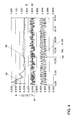
- FIG. 4 shows typical signal profiles of the lambda sensor correction explained with reference to FIG. 3.
- the individual signal curves are plotted against time t.
- a setpoint for the slope of the setpoint characteristic curve 32, ie d U LSU - model / d ⁇ setpoint, is shown at 60 .
- a curve of the regression factor R LSU is also shown at 62.
- a characteristic curve is plotted at 64, which represents noise of the voltage signal U LSU .
- the characteristic curve 64 oscillates here by a noise factor RF of 1.
- the characteristic curve of the voltage signal U LSU corresponding to the desired characteristic curve 32 (FIG. 2) is plotted at 66 for a lambda control of ⁇ 3%. This means that the value ⁇ target fluctuates (toggles) by a value of 0.97 to 1.03.
- the signal disturbances actually present by the noise signals 64 lead to a characteristic curve 68, which results from a superimposition of the characteristic curve 66 with the characteristic curve 64.
- the characteristic curve 66 thus corresponds to the desired signal, while the characteristic curve 68 corresponds to the actual signal.
- the regression factor R LSU approaches the characteristic curve 60, which corresponds to the nominal slope of the characteristic curve 32, after a short time.
- the regression factor 62 is recalculated for all newly added measured value pairs, this is the actual measured voltage U LSU of the lambda probe 16 and the value ⁇ target at any time, over all measured values of the measurement cycle.
- the measuring cycle begins, for example, each time the internal combustion engine 10 is restarted.
- the number of measured values included in the regression increases with each new pair of measured values. It becomes clear that after a short time, in particular within a few seconds, the course 62 of the regression factor approaches the course of the characteristic curve 60.
- the lambda probe correction can cause the gradient of the actual characteristic curve 34 to deviate from the target characteristic curve 32 for each linear broadband lambda probe 16. This deviation can be caused by manufacturing tolerances, aging or signs of poisoning. This is not a criterion for the correction of the lambda probe voltage signal U LSU .
- the on-board diagnosis of the motor vehicle having the internal combustion engine 10 can be carried out simultaneously by the lambda sensor correction. If the regression factor R LSU and / or the correction factor K LSU is so large that the deviation of the actual characteristic curve 34 from the target characteristic curve 32 exceeds a predeterminable maximum deviation, an error of the lambda probe 16 which can no longer be caused by the inventive method can be derived from this Correction can be compensated, be closed. The exchange of the corresponding lambda probe 16 can be displayed by providing a corresponding signal.
Landscapes
- Engineering & Computer Science (AREA)
- Chemical & Material Sciences (AREA)
- Combustion & Propulsion (AREA)
- Mechanical Engineering (AREA)
- General Engineering & Computer Science (AREA)
- Analytical Chemistry (AREA)
- Electrical Control Of Air Or Fuel Supplied To Internal-Combustion Engine (AREA)
- Combined Controls Of Internal Combustion Engines (AREA)
- Output Control And Ontrol Of Special Type Engine (AREA)
Abstract
Description
Die Erfindung betrifft ein Verfahren zur Regelung einer Verbrennungskraftmaschine mit den im Oberbegriff des Anspruchs 1 genannten Merkmalen sowie eine Vorrichtung mit den im Obergriff des Anspruchs 8 genannten Merkmalen.The invention relates to a method for controlling an internal combustion engine the features mentioned in the preamble of claim 1 and a device with the features mentioned in the preamble of claim 8.
Zur Regelung eines Betriebsmodus einer Verbrennungskraftmaschine ist es bekannt, in einem Abgaskanal wenigstens eine Lambdasonde anzuordnen. Mit Hilfe der Lambdasonde kann eine Restsauerstoffkonzentration in dem Abgas erfasst werden und hieraus ein Rückschluss auf das Verhältnis eines Sauerstoffanteils zu einem Kraftstoffanteil in einem dem Verbrennungsprozess zugeführten Luft-Kraftstoff-Gemisch erfolgen.To control an operating mode of an internal combustion engine, it is known in to arrange at least one lambda probe in an exhaust gas duct. With the help of Lambda probe, a residual oxygen concentration in the exhaust gas can be detected and from this a conclusion on the ratio of an oxygen fraction to one Fuel fraction in an air-fuel mixture supplied to the combustion process respectively.
Ein von der Lambdasonde bereitgestelltes Signal wird einem Motorsteuergerät zugeführt, das hieraus ein die Zusammensetzung des Kraftstoff-Luft-Gemisches beeinflussendes Stellsignal generiert. Mittels diesem Stellsignal kann beispielsweise eine Kraftstoffeinspritzung oder eine Luftmengenzuführung zu der Verbrennungskraftmaschine geregelt werden.A signal provided by the lambda probe is fed to an engine control unit, this results in an influence on the composition of the fuel-air mixture Control signal generated. Using this control signal, for example Fuel injection or an air supply to the Internal combustion engine to be regulated.
Bekannt sind sogenannte Zweipunkt-Lambdasonden, die eine stark nicht lineare Kennlinie mit einem sehr steilen Übergang bei λ = 1 aufweisen. Mittels derartiger Lambdasonden lassen sich nur zwei Zustände erfassen, nämlich Kraftstoff liegt im stöchiometrischen Überschuss oder Luft liegt im stöchiometrischen Überschuss des Kraftstoff-Luftgemisches vor.So-called two-point lambda probes are known, which are highly non-linear Have a characteristic curve with a very steep transition at λ = 1. By means of such Lambda sensors can only detect two states, namely there is fuel in the stoichiometric excess or air is in the stoichiometric excess of Air-fuel mixture before.
Um eine verbesserte Lambdaregelung der Verbrennungskraftmaschine zu erreichen, insbesondere auch um für unterschiedliche Betriebsmodi der Verbrennungskraftmaschine, wie beispielsweise Kaltstart oder Volllast, beziehungsweise für unterschiedliche Typen von Verbrennungskraftmaschinen, wie beispielsweise Schichtlademotoren oder Magermotoren, ist der Einsatz sogenannter Breitband-Lambdasonden bekannt. Diese Breitband-Lambdasonden zeichnen sich durch eine lineare Kennlinie aus, die über einen großen Bereich, beispielsweise λ = 0,7 bis 5, verläuft. Mittels derartiger linearer Breitband-Lambdasonden kann eine kontinuierliche Lambdaregelung ausgeführt werden, deren Sollwert im gesamten Messbereich der linearen Breitband-Lambdasonde liegen kann. Derartige lineare Breitband-Lambdasonden zeichnen sich darüber hinaus durch ein schnelleres Ansprechen und eine genauere Regelung aus.In order to achieve improved lambda control of the internal combustion engine, in particular for different operating modes Internal combustion engine, such as cold start or full load, respectively for different types of internal combustion engines, such as Stratified charge engines or lean-burn engines is the use of so-called broadband lambda sensors known. These broadband lambda sensors are characterized by a linear characteristic curve, which over a large range, for example λ = 0.7 to 5, runs. With such linear broadband lambda probes, a continuous Lambda control are carried out, the setpoint of which in the entire measuring range linear broadband lambda probe. Such linear broadband lambda probes are also characterized by a faster response and a more precise regulation.
Beim Einsatz derartiger linearer Breitband-Lambdasonden ist jedoch nachteilig, dass diese, bedingt durch Herstellungstoleranzen, Alterungseinflüsse, Vergiftungseinflüsse oder dergleichen, einen Offset oder eine Steigungsabweichung in der Kennlinie haben können, die eine genaue Regelung beeinträchtigen. Insbesondere bei relativ weit von λ = 1 liegenden Regelwerten für Lambda weitet sich ein Fehlerband (Toleranzband) der linearen Kennlinie auf. Der Verlauf der linearen Kennlinie ist insbesondere bei mageren Kraftstoff-Luft-Gemischen mit λ > 1 relativ flach, so dass dort Abweichungen in der Kennlinie zu relativ großen Fehlern führen. Derartige Fehler führen dazu, dass gegenüber dem gewünschten Lambda ein falsches Lambda eingeregelt wird. Hieraus resultiert eine Beeinträchtigung der Verbrennungsqualität, eine höhere Schadstoffemission sowie ein erhöhter Kraftstoffverbrauch.When using such linear broadband lambda probes, however, it is disadvantageous that these, due to manufacturing tolerances, aging influences, poisoning influences or the like, have an offset or a slope deviation in the characteristic can affect the precise regulation. Especially at a relatively far from λ = 1 lying control values for lambda an error band (tolerance band) widens linear characteristic. The course of the linear characteristic curve is particularly lean Fuel-air mixtures with λ> 1 relatively flat, so that there are deviations in the Characteristic curve lead to relatively large errors. Such errors lead to the fact that an incorrect lambda is adjusted in relation to the desired lambda. Out of this results in an impairment of the combustion quality, a higher one Pollutant emissions and increased fuel consumption.
Aus der DE 196 29 552 C1 ist eine Vorrichtung zum Kompensieren der Temperaturdrift einer linearen Breitband-Lambdasonde bekannt. Hier wird vorgeschlagen, in einem Steuergerät ein Kennfeld abzulegen, das abhängig von der Arbeitstemperatur der Lambdasonde zugehörige Werte für das Ausgangssignal beinhaltet. Hierdurch wird möglich, abhängig von der Ist-Temperatur, eine Temperaturdrift der Lambdasonde auszugleichen.DE 196 29 552 C1 describes a device for compensating for the temperature drift a linear broadband lambda probe known. Here it is suggested in one Control unit to store a map that depends on the working temperature of the Lambda probe contains associated values for the output signal. This will possible, depending on the actual temperature, a temperature drift of the lambda sensor compensate.
Aus der DE 195 45 706 A1 ist ein Verfahren zur Kalibrierung einer Zweipunkt-Lambdasonde in einer Verbrennungskraftmaschine bekannt, bei dem ein Katalysator während eines bestimmten Zeitraums mit einem überfetteten Kraftstoff-Luft-Gemisch versorgt wird und während dieses Zeitraums die Signalwerte der Lambdasonde unabhängig von anderen Regelsignalen gemessen werden. Hierdurch soll ein Korrekturwert gebildet werden, der bei Normalbetrieb der Verbrennungskraftmaschine dem Sondensignal zugeführt wird. DE 195 45 706 A1 describes a method for calibrating a two-point lambda probe known in an internal combustion engine in which a catalyst for a certain period of time with an over-rich fuel-air mixture is supplied and the signal values of the lambda probe during this period can be measured independently of other control signals. This is supposed to Correction value are formed during normal operation of the internal combustion engine is fed to the probe signal.
Aus der EP 0 686 232 B1 ist bekannt, eine lineare Breitband-Lambdasonde mit einer Zweipunkt-Lambdasonde zu kombinieren, um die lineare Breitband-Lambdasonde bei einem Wert λ = 1 mittels der Zweipunkt-Lambdasonde zu kalibrieren.EP 0 686 232 B1 discloses a linear broadband lambda probe with a Combine two-point lambda probe to create the linear broadband lambda probe to calibrate a value λ = 1 using the two-point lambda probe.
Die US-PS 5,473,889 beschreibt eine Anordnung, bei der einerseits eine lineare Breitband-Lambdasonde und andererseits eine weitere Gasmess-Sonde vorgesehen sind. Anhand der von den beiden Sonden gelieferten Messergebnisse soll das von der linearen Breitband-Lambdasonde gelieferte Signal verifiziert werden.US Pat. No. 5,473,889 describes an arrangement in which, on the one hand, a linear Broadband lambda probe and, on the other hand, a further gas measuring probe are provided are. Based on the measurement results provided by the two probes, the linear broadband lambda probe signal can be verified.
Schließlich ist aus der EP 0 894 187 B1 ein Verfahren zur modellgestützten Instationärsteuerung einer Verbrennungskraftmaschine bekannt, bei der Kraftstoffablagerungen im Saugrohr mittels eines sogenannten Wandfilmmodells berücksichtigt werden, wobei die Parameter des Wandfilmmodells unter anderem aus einem Ausgangssignal einer im Abgastrakt der Verbrennungskraftmaschine angeordneten linearen Breitband-Lambdasonde adaptiert werden.Finally, EP 0 894 187 B1 describes a method for model-based Transient control of an internal combustion engine is known in which Fuel deposits in the intake manifold using a so-called wall film model are taken into account, whereby the parameters of the wall film model include an output signal of one in the exhaust tract of the internal combustion engine arranged linear broadband lambda probe can be adapted.
Aus der allgemeinen Messtechnik sind sogenannte Regressionsrechnungen bekannt, mittels denen eine Näherungskurve aus einer gegebenen Anzahl von Messpunkten bestimmt werden kann. Im Ergebnis der Regressionsrechnung sind Parameter der Näherungskurve, beispielsweise eine Steigung einer Geraden beziehungsweise ein Offset, darstellbar.So-called regression calculations are known from general measurement technology, by means of which an approximation curve from a given number of measuring points can be determined. In the result of the regression calculation, parameters are the Approximation curve, for example a slope of a straight line or a Offset, representable.
Der Erfindung liegt die Aufgabe zugrunde, ein Verfahren und eine Vorrichtung der gattungsgemäßen Art anzugeben, mittels denen in einfacher Weise eine genaue Lambdaregelung von Verbrennungskraftmaschinen in einem großen Regelbereich durchführbar ist.The invention has for its object a method and an apparatus Specify generic type, by means of which an accurate Lambda control of internal combustion engines in a wide control range is feasible.
Erfindungsgemäß wird diese Aufgabe durch ein Verfahren mit den im Anspruch 1 genannten Merkmalen und eine Vorrichtung mit den im Anspruch 8 genannten Merkmalen gelöst. Dadurch, dass eine Steigung der Ist-Kennlinie der linearen Breitband-Lambdasonde - während des bestimmungsgemäßen Einsatzes der linearen Breitband-Lambdasonde bei der Regelung einer Verbrennungskraftmaschine - ermittelt wird, eine Abweichung der Steigung von einer Soll-Kennlinie ermittelt wird und aus der Abweichung ein Korrekturwert ermittelt wird, mit dem das Stellsignal für die Beeinflussung der Zusammensetzung des Kraftstoff-Luft-Gemisches zum Betrieb der Verbrennungskraftmaschine korrigiert wird, ist vorteilhaft möglich, selbsttätig fortlaufend die Ist-Kennlinie der linearen Breitband-Lambdasonde anzupassen. Somit können insbesondere ohne zusätzlichen Bauelementeaufwand, beispielsweise durch zusätzliche Sonden oder dergleichen, zum Kalibrieren der linearen Breitband-Lambdasonde exakte Lambdawerte vorgegeben werden. Ferner wird hierdurch vorteilhaft möglich, bei der Herstellung der linearen Breitband-Lambdasonden größere Fertigungstoleranzen zuzulassen, da während des bestimmungsgemäßen Einsatzes der Lambdasonden eine automatische Kompensation der vorhandenen Ist-Fehler erfolgt. Hierdurch kommt es zu einer Reduzierung der Produktionskosten, da Anforderungen an Qualitätsüberwachung usw. verringert werden können und andererseits die Ausbeute des Herstellungsprozesses erhöht ist.According to the invention, this object is achieved by a method with the method described in claim 1 Features mentioned and a device with those mentioned in claim 8 Features resolved. Because an increase in the actual characteristic curve of the linear broadband lambda probe - During the intended use of the linear broadband lambda sensor in the control of an internal combustion engine - is determined Deviation of the slope from a target characteristic curve is determined and from the deviation a correction value is determined with which the control signal for influencing the Composition of the fuel-air mixture for operating the Correcting the internal combustion engine is advantageously possible, automatically continuously adapt the actual characteristic of the linear broadband lambda probe. So you can in particular without additional component expenditure, for example by additional Probes or the like, for calibrating the linear broadband lambda probe exact Lambda values can be specified. This also advantageously makes it possible for Manufacture of linear broadband lambda probes greater manufacturing tolerances allow, because during the intended use of the lambda sensors a the existing errors are automatically compensated. This is what happens a reduction in production costs due to quality monitoring requirements etc. can be reduced and on the other hand the yield of Manufacturing process is increased.
Ferner ist vorteilhaft möglich, durch das erfindungsgemäße Verfahren alterungsbedingte beziehungsweise vergiftungsbedingte Änderungen der Kennlinien zu kompensieren, so dass die Standzeit der linearen Breitband-Lambdasonden erhöht werden kann.Furthermore, it is advantageously possible for the method according to the invention to be age-related or to compensate for changes in the characteristic curves caused by poisoning that the service life of the linear broadband lambda sensors can be increased.
In bevorzugter Ausgestaltung der Erfindung ist vorgesehen, dass die Steigung der Ist-Kennlinie durch eine Regressionsrechnung ermittelt wird, bei der vorzugsweise die Regressionsrechnung die Ausgangssignale der linearen Breitband-Lambdasonde und ein Lambdasoll-Signal zum Betrieb der Verbrennungskraftmaschine auswertet. Durch eine derartige Verknüpfung der Signale lässt sich ein Regressionsfaktor ermitteln, der die mittlere Steigung der Ist-Kennlinie im Punkt des Lambda-Soll-Mittelwertes darstellt. Dieser Regressionsfaktor kann bevorzugt mit der Soll-Kennlinie der eingesetzten linearen Breitband-Lambdasonde sowie dem Lambda-Soll-Wert verknüpft werden, so dass ein Korrekturfaktor zur Verfügung steht, mittels dem das von der linearen Breitband-Lambdasonde gelieferte Signal korrigiert werden kann. Hierdurch wird eine exakte Lambdaregelung der Verbrennungskraftmaschine, insbesondere auch über einen weiten Lambdaregelbereich, in fetten und mageren Betriebsmodi die Verbrennungskraftmaschine möglich.In a preferred embodiment of the invention it is provided that the slope of the actual characteristic curve is determined by a regression calculation, in which preferably the Regression calculation the output signals of the linear broadband lambda probe and evaluates a lambda target signal for operating the internal combustion engine. By Such a linkage of the signals can be used to determine a regression factor, which is the represents the average slope of the actual characteristic curve at the point of the lambda target mean value. This regression factor can preferably be used with the desired characteristic curve linear broadband lambda probe and the desired lambda value are linked, so that a correction factor is available by means of which the linear Broadband lambda sensor supplied signal can be corrected. This will create a exact lambda control of the internal combustion engine, in particular also via a wide lambda control range, in rich and lean operating modes Internal combustion engine possible.
Ferner wird durch das erfindungsgemäße Verfahren in einfacher Weise eine Onboard-Diagnose möglich, da durch die Regression die Abweichung der tatsächlichen Kennlinie der linearen Breitband-Lambdasonde von der idealen Kennlinie ermittelbar ist. Diese Abweichung der tatsächlichen von der idealen Kennlinie kann in einfacher Weise mit einer maximal zulässigen Abweichung verglichen werden, so dass bei Überschreiten der maximal zulässigen Abweichungen auf einen Fehlerfall erkannt wird, der beispielsweise einen Austausch der linearen Breitband-Lambdasonde erfordert. Furthermore, the method according to the invention makes onboard diagnosis simple possible because the regression means the deviation of the actual characteristic the linear broadband lambda probe can be determined from the ideal characteristic curve. This Deviation of the actual from the ideal characteristic can be done in a simple manner a maximum allowable deviation are compared so that when the maximum permissible deviations to an error case is detected, for example an exchange of the linear broadband lambda probe requires.
Weitere bevorzugte Ausgestaltungen der Erfindung ergeben sich aus den übrigen, in den Unteransprüchen genannten Merkmalen.Further preferred refinements of the invention result from the others in the Characteristics mentioned subclaims.
Die Erfindung wird nachfolgend in einem Ausführungsbeispiel anhand der zugehörigen Zeichnungen näher erläutert. Es zeigen:
- Figur 1
- schematisch eine mit einer Lambdaregelung ausgestattete Verbrennungskraftmaschine;
Figur 2- zwei Kennlinien von linearen Breitband-Lambdasonden;
- Figur 3
- ein Blockschaltbild der erfindungsgemäßen Lambdasondenkorrektur und
- Figur 4
- den Verlauf einzelner Kennlinien der erfindungsgemäßen Lambdasondenkorrektur.
- Figure 1
- schematically an internal combustion engine equipped with a lambda control;
- Figure 2
- two characteristics of linear broadband lambda probes;
- Figure 3
- a block diagram of the lambda sensor correction and
- Figure 4
- the course of individual characteristic curves of the lambda sensor correction according to the invention.
Figur 1 zeigt schematisch eine Verbrennungskraftmaschine 10, deren Abgasleitung 12
mit einem Katalysator, insbesondere einem 3-Wege-Katalysator 14, verbunden ist. In der
Abgasleitung 12 ist eine lineare Breitband-Lambdasonde 16 (nachfolgend Lambdasonde
16) angeordnet. Eine Signalleitung 18 der Lambdasonde 16 ist mit einem
Motorsteuergerät 20 verbunden.FIG. 1 schematically shows an
Die Verbrennungskraftmaschine 10 umfasst ferner eine Ansaugleitung 22, in der ein
Mittel 24 zum Einstellen einer Ansaugluftmenge angeordnet ist. Ferner ist ein Mittel 26
zum Einbringen, beispielsweise Einspritzen, eines Kraftstoffes in die
Verbrennungskraftmaschine 10, insbesondere in die Ansaugluft, vorgesehen. Die Mittel
24 und 26 sind jeweils über Steuerleitungen 28 beziehungsweise 30 ebenfalls mit dem
Motorsteuergerät 20 verbunden. Das Motorsteuergerät 20 besitzt weitere, hier lediglich
angedeutete Anschlüsse, mit denen eine Vielzahl von Überwachungen, Steuerungen,
Regelungen oder dergleichen der Verbrennungskraftmaschine 10 übernommen werden
können. Auf diese wird jedoch im Rahmen der vorliegenden Beschreibung nicht näher
eingegangen.The
Die allgemeine Funktionsweise der in Figur 1 gezeigten schematischen Anordnung ist folgende: The general mode of operation of the schematic arrangement shown in FIG. 1 is the following:
In der Verbrennungskraftmaschine 10 wird ein Kraftstoff-Luft-Gemisch verbrannt, um
eine Antriebsenergie, beispielsweise für ein Kraftfahrzeug, zu erzeugen. Das Abgas des
Verbrennungsprozesses wird über die Abgasleitung 12 einem Katalysator 14, mittels
dem beispielsweise Stickoxide NOx, Kohlenwasserstoffe HC oder Kohlenmonoxid CO
absorbiert werden, zugeführt. Das Abgas wird hierbei an der Lambdasonde 16
vorbeigeführt, mittels der ein Restsauerstoffgehalt des Abgases 12 in bekannter Weise
messbar ist. Ein dem Restsauerstoffgehalt entsprechendes Signal wird von der
Lambdasonde 16 dem Motorsteuergerät 20 übermittelt. Das Motorsteuergerät 20 stellt
Steuersignale für die Mittel 24 und 26 bereit, mittels denen einen Luftmenge und/oder
eine Kraftstoffmenge für das in der Verbrennungskraftmaschine 10 zu verbrennende
Kraftstoff-Luft-Gemisch dosiert wird. Entsprechend einem vorgegebenen Lambdawert
wird hierbei das von der Lambdasonde 16 bereitgestellte Signal berücksichtigt.A fuel-air mixture is burned in the
In Figur 2 ist eine Kennlinie der linearen Breitband-Lambdasonde 16 mit 32 bezeichnet.
Hierbei ist die Ausgangsspannung ULSU der Lambdasonde 16 über dem Wert Lambda
aufgetragen. Übliche Lambdasonden 16 besitzen bei einem Lambdawert = 1 eine
Ausgangsspannung U von 2,5 V. Zum Vergleich ist eine zweite Kennlinie 34 eingetragen,
die fehlerbehaftet ist. Diese weist eine insgesamt geringere Steigung um den Wert λ = 1
auf. Dies bedeutet, diese fehlerhafte Kennlinie 34 besitzt im mageren Bereich (λ > 1)
eine zu niedrige Ausgangsspannung ULSU und im fetten Bereich (λ < 1) eine zu hohe
Ausgangsspannung ULSU. Dies führt dazu, dass um den Wert λ = 1 ein Gradient Δ ULSU
34 kleiner ist als ein Gradient Δ ULSU 32, da die Kennlinie 34 um den Wert λ = 1 eine
geringere Steigung aufweist.A characteristic curve of the linear
Derartige fehlerhafte Kennlinienverläufe 34 können beispielsweise durch
Fertigungstoleranzen, Alterungserscheinungen oder Vergiftungserscheinungen auftreten.
In jedem Fall führt dies zu einer Abweichung der Steigung der Ist-Kennlinie 34 von der
Soll-Kennlinie 32.Such faulty
Figur 3 zeigt in einem Blockschaltbild die erfindungsgemäße Lambdasondenkorrektur,
mittels der beim bestimmungsgemäßen Einsatz der Lambdasonde 16 (Figur 1) der
beispielsweise anhand von Figur 2 erläuterte Offset der Kennlinie 34 von der Soll-Kennlinie
32 ausgeglichen werden kann. FIG. 3 shows the lambda probe correction according to the invention in a block diagram,
by means of the when the lambda probe 16 (FIG. 1) is used as intended
for example, the offset of the
Die einzelnen Bauelemente der Lambdasondenkorrektur sind in das Motorsteuergerät 20
integriert.The individual components of the lambda sensor correction are in the
Das Spannungssignal ULSU der Lambdasonde 16 wird einerseits einer
Regressionsrechnung 36 und andererseits einem Subtrahierglied 38 zugeführt. Der
Regressionsrechnung 36 wird ferner ein Signal λSoll zugeführt. Das Signal λSoll wird
ferner einem Speichermittel 40 zugeführt, in dem die Soll-Kennlinie 32 abgespeichert ist.
Anhand der im Speichermittel 40 abgelegten Kennlinie 32 wird aus dem Signal λSoll ein
Signal ULSU-modell ermittelt, das einem Differenzierglied 42 zugeführt wird. Das
Differenzierglied 42 wird gleichzeitig mit dem Signal λSoll beaufschlagt. Am Ausgang des
Differenziergliedes 42 liegt ein Signal d ULSU-modell / d λSoll an, das der Sollsteigung der
Kennlinie 32 entspricht.The voltage signal U LSU of the
Am Ausgang der Regressionsrechnung 36 liegt ein Signal d ULSU /dλ Soll an, das der Ist-Steigung
der Kennlinie 34 entspricht. Dieses Signal entspricht dem Regressionsfaktor
RLSU der Lambdasonde 16. Dieser stellt die mittlere Steigung der Ist-Kennlinie 34 im
Punkt des Lambdasoll-Mittelwertes dar. Über ein Verhältnisglied 44 wird der
Regressionsfaktor RLSU mit der Sollsteigung der Kennlinie 32 verknüpft und einem
Adaptionsglied 46 zugeführt. Das Adaptionsglied 46 ermittelt aus dem Eingangssignal
einen Korrekturfaktor KLSU für die Lambdasonde 16.At the output of the
Das Ist-Signal ULSU der Lambdasonde 16 wird über das Subtrahierglied 38 mit einer
Spannung von 2,5 V, die der Sollspannung bei λ = 1 entspricht, verknüpft. Die sich
hieraus ergebende Differenz wird über ein Multiplizierglied 48 mit dem Korrekturfaktor
LSU verknüpft. Das Multiplizierglied 48 ist mit einem Summierglied 50 verbunden, über
das der zuvor im Subtrahierglied 38 abgezogene Spannungswert 2,5 V dem Signal
wieder aufaddiert wird, so dass als Ausgangssignal ein korrigiertes Spannungssignal
ULSU-korrigiert der Lambdasonde 16 zur Verfügung steht und durch das Motorsteuergerät 20
(Figur 1) für die Regelung der Verbrennungskraftmaschine 10 eingesetzt werden kann.The actual signal U LSU of the
Es wird deutlich, dass durch die Signalverarbeitung erreicht wird, dass eine Abweichung
der Steigung der Ist-Kennlinie 34 von der Steigung der Soll-Kennlinie 32 in einfacher
Weise korrigiert werden kann.It is clear that signal processing achieves that deviation
the slope of the actual
In Figur 4 werden typische Signalverläufe der anhand von Figur 3 erläuterten
Lambdasondenkorrektur gezeigt. Hierbei sind die einzelnen Signalverläufe über der Zeit t
aufgetragen. Mit 60 ist ein Sollwert für die Steigung der Soll-Kennlinie 32, also d U LSU--modell
/ d λSoll dargestellt. Ferner ist mit 62 ein Verlauf des Regressionsfaktors RLSU
dargestellt. Mit 64 ist eine Kennlinie aufgetragen, die ein Rauschen des
Spannungssignals ULSU darstellt. Die Kennlinie 64 oszilliert hierbei um einen
Rauschfaktor RF von 1.FIG. 4 shows typical signal profiles of the lambda sensor correction explained with reference to FIG. 3. The individual signal curves are plotted against time t. A setpoint for the slope of the setpoint
Mit 66 ist die Kennlinie des Spannungssignals ULSU entsprechend der Soll-Kennlinie 32
(Figur 2) für eine Lambdaregelung von ± 3 % aufgetragen. Dies bedeutet, der Wert λSoll
schwankt (toggelt) um einen Wert von 0,97 bis 1,03. Die durch die Rauschsignale 64
tatsächlich vorhandenen Signalstörungen führen zu einem Kennlinienverlauf 68, der aus
einer Überlagerung des Kennlinienverlaufs 66 mit der Kennlinie 64 resultiert. Die
Kennlinie 66 entspricht somit dem Sollsignal, während die Kennlinie 68 dem Ist-Signal
entspricht. Anhand der Kennlinie 62 wird deutlich, dass der Regressionsfaktor RLSU
schon nach kurzer Zeit sich dem Verlauf der Kennlinie 60, die der Sollsteigung der
Kennlinie 32 entspricht, annähert. Der Regressionsfaktor 62 wird bei jedem neu
hinzukommenden Messwertpaar, dies ist die tatsächliche Mess-Spannung ULSU der
Lambdasonde 16 und des Wertes λSoll zu einem beliebigen Zeitpunkt, neu über alle
Messwerte des Messzyklus berechnet. Der Messzyklus beginnt beispielsweise bei jedem
Neustart der Verbrennungskraftmaschine 10. Hierdurch nimmt die Anzahl der in die
Regression einbezogenen Messwerte mit jedem neuen Messwertpaar zu. Es wird
deutlich, dass bereits nach kurzer Zeit, insbesondere innerhalb weniger Sekunden, der
Verlauf 62 des Regressionsfaktors den Verlauf der Kennlinie 60 sich annähert.The characteristic curve of the voltage signal U LSU corresponding to the desired characteristic curve 32 (FIG. 2) is plotted at 66 for a lambda control of ± 3%. This means that the value λ target fluctuates (toggles) by a value of 0.97 to 1.03. The signal disturbances actually present by the noise signals 64 lead to a
Anhand dieser modellhaften Darstellung der Kennlinien wird deutlich, dass trotz
Überlagerung des Lambdasollsignals (Kennlinie 66) durch das Rauschsignal 64 das
Ausgangssignal ULSU korrigiert (Figur 3) durch die fortlaufende Ermittlung des
Regressionsfaktors RLSU bei der Lambdaregelung der Verbrennungskraftmaschine 10 die
Abweichung der Steigung der Ist-Kennlinie 34 von der Soll-Kennlinie 32 kompensiert.On the basis of this model representation of the characteristic curves, it is clear that, despite the superposition of the lambda target signal (characteristic curve 66) by the
Anhand der Erläuterung wird ferner deutlich, dass durch die Lambdasondenkorrektur,
wie sie in Figur 3 gezeigt ist, eine Abweichung der Steigung der Ist-Kennlinie 34 von der
Soll-Kennlinie 32 für jede lineare Breitband-Lambdasonde 16 erfolgen kann. Diese
Abweichung kann durch Herstellungstoleranzen, durch Alterung oder durch
Vergiftungserscheinungen hervorgerufen sein. Dies stellt für die Korrektur des
Lambdasonden-Spannungssignals ULSU kein Kriterium dar. Based on the explanation, it is also clear that the lambda probe correction, as shown in FIG. 3, can cause the gradient of the actual
Durch die Lambdasondenkorrektur kann gleichzeitig eine Onboard-Diagnose des die
Verbrennungskraftmaschine 10 aufweisenden Kraftfahrzeuges durchgeführt werden. Ist
der Regressionsfaktor RLSU und/oder der Korrekturfaktor KLSU so groß, dass die
Abweichung der Ist-Kennlinie 34 von der Soll-Kennlinie 32 eine vorgebbare maximale
Abweichung übersteigt, kann hieraus auf einen Fehler der Lambdasonde 16, der nicht
mehr durch die erfindungsgemäße Korrektur kompensiert werden kann, geschlossen
werden. Durch Bereitstellen eines entsprechenden Signals kann der Austausch der
entsprechenden Lambdasonde 16 angezeigt werden. The on-board diagnosis of the motor vehicle having the
- 1010th
- VerbrennungskraftmaschineInternal combustion engine
- 1212th
- AbgasleitungExhaust pipe
- 1414
- 3-Wege-Katalysator3-way catalytic converter
- 1616
- Breitband-LambdasondeBroadband lambda sensor
- 1818th
- SignalleitungSignal line
- 2020th
- MotorsteuergerätEngine control unit
- 2222
- AnsaugleitungSuction pipe
- 2424th
- Mittelmedium
- 2626
- Mittelmedium
- 2828
- SteuerleitungenControl lines
- 3030th
- SteuerleitungenControl lines
- 3232
- Soll-KennlinieTarget characteristic
- 3434
- Ist-KennlinieActual characteristic
- 3636
- RegressionsrechnungRegression calculation
- 3838
- SubtrahiergliedSubtractor
- 4040
- SpeichermittelStorage means
- 4242
- DifferenziergliedDifferentiator
- 4444
- VerhältnisgliedRelationship
- 4646
- AdaptionsgliedAdapter
- 4848
- MultipliziergliedMultiplier
- 5050
- SummiergliedSummer
- 6060
-
Sollwert für die Steigung der Soll-Kennlinie 32Setpoint for the slope of the set
characteristic curve 32 - 6262
- Verlauf des Regressionsfaktors RLSU Course of the regression factor R LSU
- 6464
- RauschsignaleNoise signals
- 6666
- KennlinienverlaufCharacteristic curve
- 6868
- KennlinienverlaufCharacteristic curve
- ULSU U LSU
- Lambdasonden-SpannungssignalLambda probe voltage signal
- RLSU R LSU
- RegressionsfaktorRegression factor
- KLSU K LSU
- KorrekturfaktorCorrection factor
- RFRF
- RauschfaktorNoise factor
Claims (8)
Applications Claiming Priority (2)
| Application Number | Priority Date | Filing Date | Title |
|---|---|---|---|
| DE10016886 | 2000-04-05 | ||
| DE10016886A DE10016886A1 (en) | 2000-04-05 | 2000-04-05 | Method and device for regulating an internal combustion engine |
Publications (3)
| Publication Number | Publication Date |
|---|---|
| EP1143132A2 true EP1143132A2 (en) | 2001-10-10 |
| EP1143132A3 EP1143132A3 (en) | 2002-08-07 |
| EP1143132B1 EP1143132B1 (en) | 2006-06-14 |
Family
ID=7637646
Family Applications (1)
| Application Number | Title | Priority Date | Filing Date |
|---|---|---|---|
| EP01106488A Expired - Lifetime EP1143132B1 (en) | 2000-04-05 | 2001-03-26 | Method and device for controlling an internal combustion engine |
Country Status (3)
| Country | Link |
|---|---|
| EP (1) | EP1143132B1 (en) |
| AT (1) | ATE330117T1 (en) |
| DE (2) | DE10016886A1 (en) |
Cited By (4)
| Publication number | Priority date | Publication date | Assignee | Title |
|---|---|---|---|---|
| WO2002081887A2 (en) * | 2001-04-05 | 2002-10-17 | Siemens Aktiengesellschaft | Method for purifying exhaust gas of an internal combustion engine |
| WO2008122369A3 (en) * | 2007-04-04 | 2008-11-27 | Volkswagen Ag | Lambda control with adaptation of characteristic curves |
| FR2981697A1 (en) * | 2011-10-24 | 2013-04-26 | Bosch Gmbh Robert | METHOD AND DEVICE FOR ADAPTING A LAMBDA REGULATION |
| WO2013171015A1 (en) * | 2012-05-15 | 2013-11-21 | Robert Bosch Gmbh | Method and control unit for compensating a voltage offset in a two-point lambda probe |
Families Citing this family (1)
| Publication number | Priority date | Publication date | Assignee | Title |
|---|---|---|---|---|
| US10190520B1 (en) | 2017-10-12 | 2019-01-29 | Harley-Davidson Motor Company Group, LLC | Signal conditioning module for a wide-band oxygen sensor |
Citations (5)
| Publication number | Priority date | Publication date | Assignee | Title |
|---|---|---|---|---|
| US5473889A (en) | 1993-09-24 | 1995-12-12 | Honda Giken Kogyo K.K. (Honda Motor Co., Ltd. In English) | Air-fuel ratio control system for internal combustion engines |
| DE19545706A1 (en) | 1995-12-07 | 1997-06-12 | Vdo Schindling | Calibration method for lambda probe in IC engine |
| EP0686232B1 (en) | 1993-02-26 | 1997-09-10 | ROTH-Technik GmbH & Co. Forschung für Automobil- und Umwelttechnik | Combination of lambda sensors |
| DE19629552C1 (en) | 1996-07-22 | 1997-12-18 | Siemens Ag | IC engine exhaust gas probe temp. drift compensation device |
| EP0894187B1 (en) | 1996-04-16 | 1999-09-01 | Siemens Aktiengesellschaft | Process for model-based nonstationary control of an internal combustion engine |
Family Cites Families (7)
| Publication number | Priority date | Publication date | Assignee | Title |
|---|---|---|---|---|
| JPS61195349A (en) * | 1985-02-25 | 1986-08-29 | Ngk Spark Plug Co Ltd | Device for detecting air fuel ratio for internal-combustion engine |
| DE3928860A1 (en) * | 1989-08-31 | 1991-03-07 | Vdo Schindling | METHOD AND DEVICE FOR IMPROVING THE EXHAUST GAS BEHAVIOR OF MIXTURE COMPRESSING INTERNAL COMBUSTION ENGINES |
| DE4440639B4 (en) * | 1993-11-19 | 2007-08-23 | Aft Atlas Fahrzeugtechnik Gmbh | Method for stationary control of internal combustion engines |
| DE19819461B4 (en) * | 1998-04-30 | 2004-07-01 | Siemens Ag | Process for exhaust gas purification with trim control |
| DE19842425C2 (en) * | 1998-09-16 | 2003-10-02 | Siemens Ag | Method for correcting the characteristic of a linear lambda probe |
| DE19852244C1 (en) * | 1998-11-12 | 1999-12-30 | Siemens Ag | Controlling NOx emission in exhaust gases passing through three-way catalyst followed by lambda sensor |
| DE19919427C2 (en) * | 1999-04-28 | 2001-09-20 | Siemens Ag | Method for correcting the characteristic of a broadband lambda probe |
-
2000
- 2000-04-05 DE DE10016886A patent/DE10016886A1/en not_active Withdrawn
-
2001
- 2001-03-26 EP EP01106488A patent/EP1143132B1/en not_active Expired - Lifetime
- 2001-03-26 DE DE50110097T patent/DE50110097D1/en not_active Expired - Lifetime
- 2001-03-26 AT AT01106488T patent/ATE330117T1/en not_active IP Right Cessation
Patent Citations (5)
| Publication number | Priority date | Publication date | Assignee | Title |
|---|---|---|---|---|
| EP0686232B1 (en) | 1993-02-26 | 1997-09-10 | ROTH-Technik GmbH & Co. Forschung für Automobil- und Umwelttechnik | Combination of lambda sensors |
| US5473889A (en) | 1993-09-24 | 1995-12-12 | Honda Giken Kogyo K.K. (Honda Motor Co., Ltd. In English) | Air-fuel ratio control system for internal combustion engines |
| DE19545706A1 (en) | 1995-12-07 | 1997-06-12 | Vdo Schindling | Calibration method for lambda probe in IC engine |
| EP0894187B1 (en) | 1996-04-16 | 1999-09-01 | Siemens Aktiengesellschaft | Process for model-based nonstationary control of an internal combustion engine |
| DE19629552C1 (en) | 1996-07-22 | 1997-12-18 | Siemens Ag | IC engine exhaust gas probe temp. drift compensation device |
Cited By (7)
| Publication number | Priority date | Publication date | Assignee | Title |
|---|---|---|---|---|
| WO2002081887A2 (en) * | 2001-04-05 | 2002-10-17 | Siemens Aktiengesellschaft | Method for purifying exhaust gas of an internal combustion engine |
| WO2002081887A3 (en) * | 2001-04-05 | 2002-12-12 | Siemens Ag | Method for purifying exhaust gas of an internal combustion engine |
| WO2008122369A3 (en) * | 2007-04-04 | 2008-11-27 | Volkswagen Ag | Lambda control with adaptation of characteristic curves |
| FR2981697A1 (en) * | 2011-10-24 | 2013-04-26 | Bosch Gmbh Robert | METHOD AND DEVICE FOR ADAPTING A LAMBDA REGULATION |
| US9091226B2 (en) | 2011-10-24 | 2015-07-28 | Robert Bosch Gmbh | Method and device for adapting a lambda control |
| WO2013171015A1 (en) * | 2012-05-15 | 2013-11-21 | Robert Bosch Gmbh | Method and control unit for compensating a voltage offset in a two-point lambda probe |
| US9696289B2 (en) | 2012-05-15 | 2017-07-04 | Robert Bosch Gmbh | Method and control unit for compensating for a voltage offset of a two-point lambda sensor |
Also Published As
| Publication number | Publication date |
|---|---|
| EP1143132B1 (en) | 2006-06-14 |
| ATE330117T1 (en) | 2006-07-15 |
| DE50110097D1 (en) | 2006-07-27 |
| DE10016886A1 (en) | 2001-10-18 |
| EP1143132A3 (en) | 2002-08-07 |
Similar Documents
| Publication | Publication Date | Title |
|---|---|---|
| DE3500594C2 (en) | Metering system for an internal combustion engine to influence the operating mixture | |
| DE3823277C2 (en) | ||
| EP1327138B1 (en) | Method and device for the on-board diagnosis of an nox sensor | |
| DE102008001569B4 (en) | Method and device for adapting a dynamic model of an exhaust gas probe | |
| DE102010043238B4 (en) | Motor control system with an actuator control algorithm | |
| EP0442873B1 (en) | A process and device for lambda control | |
| DE69635917T2 (en) | Detection device of catalyst deterioration of an internal combustion engine | |
| DE19612212B4 (en) | Diagnostic device for an air / fuel ratio sensor | |
| DE69918914T2 (en) | Method and device for controlling the air-fuel ratio in an internal combustion engine | |
| WO1995031636A1 (en) | Process and device for controlling an internal combustion engine | |
| DE4192104C1 (en) | Controlling air-fuel ratio in internal combustion engine | |
| DE4122828A1 (en) | AIR FUEL RATIO CONTROL SYSTEM | |
| WO2003078816A1 (en) | Method and device for monitoring and regulating the operation of an internal combustion engine with reduced nox emissions | |
| DE102012221549A1 (en) | Method for determining gaseous mixture composition in exhaust gas passage of internal combustion engine i.e. Otto engine, involves correcting output signal of exhaust-gas sensor with quantity dependant on composition of gaseous mixture | |
| DE10256241A1 (en) | Method and device for controlling an internal combustion engine having exhaust gas recirculation | |
| DE10309422A1 (en) | Calibrating nitrogen oxide sensor in engine exhaust system, shuts off engine for interval during which decay of nitrogen oxide signal is observed and evaluated | |
| EP0187649B1 (en) | Mixture regulation apparatus for a combustion engine | |
| EP1143132B1 (en) | Method and device for controlling an internal combustion engine | |
| DE19522659C2 (en) | Fuel delivery system and method for an internal combustion engine | |
| EP0757168A2 (en) | Method and apparatus for controlling an internal combustion engine | |
| EP1227234B1 (en) | Method and apparatus for operating a NOx-sensor located in the exhaust line of an internal combustion engine | |
| WO2007065855A1 (en) | Method for the diagnosis of a catalytic converter which is arranged in an exhaust area of an internal combustion engine and device for carrying out said method | |
| WO1999056012A1 (en) | Method for purifying waste gas with trim adjustment | |
| EP1365234A2 (en) | Method for correcting the NOx signal of a NOx sensor | |
| DE10161901A1 (en) | Compensating engine exhaust gas sensor linear characteristic offset involves allowing offset compensation value determination only if reference sensor signal in tolerance field for defined time |
Legal Events
| Date | Code | Title | Description |
|---|---|---|---|
| PUAI | Public reference made under article 153(3) epc to a published international application that has entered the european phase |
Free format text: ORIGINAL CODE: 0009012 |
|
| AK | Designated contracting states |
Kind code of ref document: A2 Designated state(s): AT BE CH CY DE DK ES FI FR GB GR IE IT LI LU MC NL PT SE TR |
|
| AX | Request for extension of the european patent |
Free format text: AL;LT;LV;MK;RO;SI |
|
| PUAL | Search report despatched |
Free format text: ORIGINAL CODE: 0009013 |
|
| AK | Designated contracting states |
Kind code of ref document: A3 Designated state(s): AT BE CH CY DE DK ES FI FR GB GR IE IT LI LU MC NL PT SE TR |
|
| AX | Request for extension of the european patent |
Free format text: AL;LT;LV;MK;RO;SI |
|
| 17P | Request for examination filed |
Effective date: 20030207 |
|
| AKX | Designation fees paid |
Designated state(s): AT BE CH CY DE DK ES FI FR GB GR IE IT LI LU MC NL PT SE TR |
|
| 17Q | First examination report despatched |
Effective date: 20050512 |
|
| GRAP | Despatch of communication of intention to grant a patent |
Free format text: ORIGINAL CODE: EPIDOSNIGR1 |
|
| GRAS | Grant fee paid |
Free format text: ORIGINAL CODE: EPIDOSNIGR3 |
|
| GRAA | (expected) grant |
Free format text: ORIGINAL CODE: 0009210 |
|
| AK | Designated contracting states |
Kind code of ref document: B1 Designated state(s): AT BE CH CY DE DK ES FI FR GB GR IE IT LI LU MC NL PT SE TR |
|
| PG25 | Lapsed in a contracting state [announced via postgrant information from national office to epo] |
Ref country code: IT Free format text: LAPSE BECAUSE OF FAILURE TO SUBMIT A TRANSLATION OF THE DESCRIPTION OR TO PAY THE FEE WITHIN THE PRESCRIBED TIME-LIMIT;WARNING: LAPSES OF ITALIAN PATENTS WITH EFFECTIVE DATE BEFORE 2007 MAY HAVE OCCURRED AT ANY TIME BEFORE 2007. THE CORRECT EFFECTIVE DATE MAY BE DIFFERENT FROM THE ONE RECORDED. Effective date: 20060614 Ref country code: GB Free format text: LAPSE BECAUSE OF FAILURE TO SUBMIT A TRANSLATION OF THE DESCRIPTION OR TO PAY THE FEE WITHIN THE PRESCRIBED TIME-LIMIT Effective date: 20060614 Ref country code: IE Free format text: LAPSE BECAUSE OF FAILURE TO SUBMIT A TRANSLATION OF THE DESCRIPTION OR TO PAY THE FEE WITHIN THE PRESCRIBED TIME-LIMIT Effective date: 20060614 Ref country code: FI Free format text: LAPSE BECAUSE OF FAILURE TO SUBMIT A TRANSLATION OF THE DESCRIPTION OR TO PAY THE FEE WITHIN THE PRESCRIBED TIME-LIMIT Effective date: 20060614 Ref country code: NL Free format text: LAPSE BECAUSE OF FAILURE TO SUBMIT A TRANSLATION OF THE DESCRIPTION OR TO PAY THE FEE WITHIN THE PRESCRIBED TIME-LIMIT Effective date: 20060614 |
|
| REG | Reference to a national code |
Ref country code: GB Ref legal event code: FG4D Free format text: NOT ENGLISH |
|
| REG | Reference to a national code |
Ref country code: CH Ref legal event code: EP |
|
| REG | Reference to a national code |
Ref country code: IE Ref legal event code: FG4D Free format text: LANGUAGE OF EP DOCUMENT: GERMAN |
|
| REF | Corresponds to: |
Ref document number: 50110097 Country of ref document: DE Date of ref document: 20060727 Kind code of ref document: P |
|
| PG25 | Lapsed in a contracting state [announced via postgrant information from national office to epo] |
Ref country code: SE Free format text: LAPSE BECAUSE OF FAILURE TO SUBMIT A TRANSLATION OF THE DESCRIPTION OR TO PAY THE FEE WITHIN THE PRESCRIBED TIME-LIMIT Effective date: 20060914 Ref country code: DK Free format text: LAPSE BECAUSE OF FAILURE TO SUBMIT A TRANSLATION OF THE DESCRIPTION OR TO PAY THE FEE WITHIN THE PRESCRIBED TIME-LIMIT Effective date: 20060914 |
|
| PG25 | Lapsed in a contracting state [announced via postgrant information from national office to epo] |
Ref country code: ES Free format text: LAPSE BECAUSE OF FAILURE TO SUBMIT A TRANSLATION OF THE DESCRIPTION OR TO PAY THE FEE WITHIN THE PRESCRIBED TIME-LIMIT Effective date: 20060925 |
|
| PG25 | Lapsed in a contracting state [announced via postgrant information from national office to epo] |
Ref country code: PT Free format text: LAPSE BECAUSE OF FAILURE TO SUBMIT A TRANSLATION OF THE DESCRIPTION OR TO PAY THE FEE WITHIN THE PRESCRIBED TIME-LIMIT Effective date: 20061114 |
|
| NLV1 | Nl: lapsed or annulled due to failure to fulfill the requirements of art. 29p and 29m of the patents act | ||
| GBV | Gb: ep patent (uk) treated as always having been void in accordance with gb section 77(7)/1977 [no translation filed] |
Effective date: 20060614 |
|
| REG | Reference to a national code |
Ref country code: IE Ref legal event code: FD4D |
|
| PLBE | No opposition filed within time limit |
Free format text: ORIGINAL CODE: 0009261 |
|
| STAA | Information on the status of an ep patent application or granted ep patent |
Free format text: STATUS: NO OPPOSITION FILED WITHIN TIME LIMIT |
|
| EN | Fr: translation not filed | ||
| 26N | No opposition filed |
Effective date: 20070315 |
|
| REG | Reference to a national code |
Ref country code: CH Ref legal event code: PL |
|
| BERE | Be: lapsed |
Owner name: VOLKSWAGEN A.G. Effective date: 20070331 |
|
| PG25 | Lapsed in a contracting state [announced via postgrant information from national office to epo] |
Ref country code: BE Free format text: LAPSE BECAUSE OF NON-PAYMENT OF DUE FEES Effective date: 20070331 |
|
| PG25 | Lapsed in a contracting state [announced via postgrant information from national office to epo] |
Ref country code: MC Free format text: LAPSE BECAUSE OF NON-PAYMENT OF DUE FEES Effective date: 20070331 |
|
| PG25 | Lapsed in a contracting state [announced via postgrant information from national office to epo] |
Ref country code: CH Free format text: LAPSE BECAUSE OF NON-PAYMENT OF DUE FEES Effective date: 20070331 Ref country code: LI Free format text: LAPSE BECAUSE OF NON-PAYMENT OF DUE FEES Effective date: 20070331 |
|
| PG25 | Lapsed in a contracting state [announced via postgrant information from national office to epo] |
Ref country code: GR Free format text: LAPSE BECAUSE OF FAILURE TO SUBMIT A TRANSLATION OF THE DESCRIPTION OR TO PAY THE FEE WITHIN THE PRESCRIBED TIME-LIMIT Effective date: 20060915 Ref country code: FR Free format text: LAPSE BECAUSE OF FAILURE TO SUBMIT A TRANSLATION OF THE DESCRIPTION OR TO PAY THE FEE WITHIN THE PRESCRIBED TIME-LIMIT Effective date: 20070309 |
|
| PG25 | Lapsed in a contracting state [announced via postgrant information from national office to epo] |
Ref country code: AT Free format text: LAPSE BECAUSE OF NON-PAYMENT OF DUE FEES Effective date: 20070326 |
|
| PG25 | Lapsed in a contracting state [announced via postgrant information from national office to epo] |
Ref country code: FR Free format text: LAPSE BECAUSE OF FAILURE TO SUBMIT A TRANSLATION OF THE DESCRIPTION OR TO PAY THE FEE WITHIN THE PRESCRIBED TIME-LIMIT Effective date: 20060614 |
|
| PG25 | Lapsed in a contracting state [announced via postgrant information from national office to epo] |
Ref country code: CY Free format text: LAPSE BECAUSE OF FAILURE TO SUBMIT A TRANSLATION OF THE DESCRIPTION OR TO PAY THE FEE WITHIN THE PRESCRIBED TIME-LIMIT Effective date: 20060614 Ref country code: LU Free format text: LAPSE BECAUSE OF NON-PAYMENT OF DUE FEES Effective date: 20070326 |
|
| PG25 | Lapsed in a contracting state [announced via postgrant information from national office to epo] |
Ref country code: TR Free format text: LAPSE BECAUSE OF FAILURE TO SUBMIT A TRANSLATION OF THE DESCRIPTION OR TO PAY THE FEE WITHIN THE PRESCRIBED TIME-LIMIT Effective date: 20060614 |
|
| PGFP | Annual fee paid to national office [announced via postgrant information from national office to epo] |
Ref country code: DE Payment date: 20200331 Year of fee payment: 20 |
|
| REG | Reference to a national code |
Ref country code: DE Ref legal event code: R071 Ref document number: 50110097 Country of ref document: DE |
|
| P01 | Opt-out of the competence of the unified patent court (upc) registered |
Effective date: 20230523 |