EP1139671A2 - Image transmission system and image reproducing device - Google Patents
Image transmission system and image reproducing device Download PDFInfo
- Publication number
- EP1139671A2 EP1139671A2 EP01111143A EP01111143A EP1139671A2 EP 1139671 A2 EP1139671 A2 EP 1139671A2 EP 01111143 A EP01111143 A EP 01111143A EP 01111143 A EP01111143 A EP 01111143A EP 1139671 A2 EP1139671 A2 EP 1139671A2
- Authority
- EP
- European Patent Office
- Prior art keywords
- picture
- section
- image
- processing
- code
- Prior art date
- Legal status (The legal status is an assumption and is not a legal conclusion. Google has not performed a legal analysis and makes no representation as to the accuracy of the status listed.)
- Granted
Links
Images


Classifications
-
- H—ELECTRICITY
- H04—ELECTRIC COMMUNICATION TECHNIQUE
- H04N—PICTORIAL COMMUNICATION, e.g. TELEVISION
- H04N9/00—Details of colour television systems
- H04N9/79—Processing of colour television signals in connection with recording
- H04N9/80—Transformation of the television signal for recording, e.g. modulation, frequency changing; Inverse transformation for playback
- H04N9/804—Transformation of the television signal for recording, e.g. modulation, frequency changing; Inverse transformation for playback involving pulse code modulation of the colour picture signal components
- H04N9/8042—Transformation of the television signal for recording, e.g. modulation, frequency changing; Inverse transformation for playback involving pulse code modulation of the colour picture signal components involving data reduction
-
- H—ELECTRICITY
- H04—ELECTRIC COMMUNICATION TECHNIQUE
- H04N—PICTORIAL COMMUNICATION, e.g. TELEVISION
- H04N19/00—Methods or arrangements for coding, decoding, compressing or decompressing digital video signals
-
- H—ELECTRICITY
- H04—ELECTRIC COMMUNICATION TECHNIQUE
- H04N—PICTORIAL COMMUNICATION, e.g. TELEVISION
- H04N19/00—Methods or arrangements for coding, decoding, compressing or decompressing digital video signals
- H04N19/10—Methods or arrangements for coding, decoding, compressing or decompressing digital video signals using adaptive coding
- H04N19/169—Methods or arrangements for coding, decoding, compressing or decompressing digital video signals using adaptive coding characterised by the coding unit, i.e. the structural portion or semantic portion of the video signal being the object or the subject of the adaptive coding
- H04N19/17—Methods or arrangements for coding, decoding, compressing or decompressing digital video signals using adaptive coding characterised by the coding unit, i.e. the structural portion or semantic portion of the video signal being the object or the subject of the adaptive coding the unit being an image region, e.g. an object
- H04N19/174—Methods or arrangements for coding, decoding, compressing or decompressing digital video signals using adaptive coding characterised by the coding unit, i.e. the structural portion or semantic portion of the video signal being the object or the subject of the adaptive coding the unit being an image region, e.g. an object the region being a slice, e.g. a line of blocks or a group of blocks
-
- H—ELECTRICITY
- H04—ELECTRIC COMMUNICATION TECHNIQUE
- H04N—PICTORIAL COMMUNICATION, e.g. TELEVISION
- H04N19/00—Methods or arrangements for coding, decoding, compressing or decompressing digital video signals
- H04N19/42—Methods or arrangements for coding, decoding, compressing or decompressing digital video signals characterised by implementation details or hardware specially adapted for video compression or decompression, e.g. dedicated software implementation
- H04N19/423—Methods or arrangements for coding, decoding, compressing or decompressing digital video signals characterised by implementation details or hardware specially adapted for video compression or decompression, e.g. dedicated software implementation characterised by memory arrangements
-
- H—ELECTRICITY
- H04—ELECTRIC COMMUNICATION TECHNIQUE
- H04N—PICTORIAL COMMUNICATION, e.g. TELEVISION
- H04N19/00—Methods or arrangements for coding, decoding, compressing or decompressing digital video signals
- H04N19/50—Methods or arrangements for coding, decoding, compressing or decompressing digital video signals using predictive coding
- H04N19/503—Methods or arrangements for coding, decoding, compressing or decompressing digital video signals using predictive coding involving temporal prediction
- H04N19/51—Motion estimation or motion compensation
- H04N19/577—Motion compensation with bidirectional frame interpolation, i.e. using B-pictures
-
- H—ELECTRICITY
- H04—ELECTRIC COMMUNICATION TECHNIQUE
- H04N—PICTORIAL COMMUNICATION, e.g. TELEVISION
- H04N19/00—Methods or arrangements for coding, decoding, compressing or decompressing digital video signals
- H04N19/60—Methods or arrangements for coding, decoding, compressing or decompressing digital video signals using transform coding
- H04N19/61—Methods or arrangements for coding, decoding, compressing or decompressing digital video signals using transform coding in combination with predictive coding
-
- H—ELECTRICITY
- H04—ELECTRIC COMMUNICATION TECHNIQUE
- H04N—PICTORIAL COMMUNICATION, e.g. TELEVISION
- H04N5/00—Details of television systems
- H04N5/76—Television signal recording
- H04N5/78—Television signal recording using magnetic recording
- H04N5/782—Television signal recording using magnetic recording on tape
- H04N5/783—Adaptations for reproducing at a rate different from the recording rate
-
- H—ELECTRICITY
- H04—ELECTRIC COMMUNICATION TECHNIQUE
- H04N—PICTORIAL COMMUNICATION, e.g. TELEVISION
- H04N19/00—Methods or arrangements for coding, decoding, compressing or decompressing digital video signals
- H04N19/10—Methods or arrangements for coding, decoding, compressing or decompressing digital video signals using adaptive coding
- H04N19/102—Methods or arrangements for coding, decoding, compressing or decompressing digital video signals using adaptive coding characterised by the element, parameter or selection affected or controlled by the adaptive coding
- H04N19/13—Adaptive entropy coding, e.g. adaptive variable length coding [AVLC] or context adaptive binary arithmetic coding [CABAC]
-
- H—ELECTRICITY
- H04—ELECTRIC COMMUNICATION TECHNIQUE
- H04N—PICTORIAL COMMUNICATION, e.g. TELEVISION
- H04N19/00—Methods or arrangements for coding, decoding, compressing or decompressing digital video signals
- H04N19/30—Methods or arrangements for coding, decoding, compressing or decompressing digital video signals using hierarchical techniques, e.g. scalability
-
- H—ELECTRICITY
- H04—ELECTRIC COMMUNICATION TECHNIQUE
- H04N—PICTORIAL COMMUNICATION, e.g. TELEVISION
- H04N19/00—Methods or arrangements for coding, decoding, compressing or decompressing digital video signals
- H04N19/70—Methods or arrangements for coding, decoding, compressing or decompressing digital video signals characterised by syntax aspects related to video coding, e.g. related to compression standards
-
- H—ELECTRICITY
- H04—ELECTRIC COMMUNICATION TECHNIQUE
- H04N—PICTORIAL COMMUNICATION, e.g. TELEVISION
- H04N19/00—Methods or arrangements for coding, decoding, compressing or decompressing digital video signals
- H04N19/90—Methods or arrangements for coding, decoding, compressing or decompressing digital video signals using coding techniques not provided for in groups H04N19/10-H04N19/85, e.g. fractals
- H04N19/91—Entropy coding, e.g. variable length coding [VLC] or arithmetic coding
-
- H—ELECTRICITY
- H04—ELECTRIC COMMUNICATION TECHNIQUE
- H04N—PICTORIAL COMMUNICATION, e.g. TELEVISION
- H04N5/00—Details of television systems
- H04N5/76—Television signal recording
- H04N5/84—Television signal recording using optical recording
- H04N5/85—Television signal recording using optical recording on discs or drums
-
- H—ELECTRICITY
- H04—ELECTRIC COMMUNICATION TECHNIQUE
- H04N—PICTORIAL COMMUNICATION, e.g. TELEVISION
- H04N9/00—Details of colour television systems
- H04N9/79—Processing of colour television signals in connection with recording
- H04N9/80—Transformation of the television signal for recording, e.g. modulation, frequency changing; Inverse transformation for playback
- H04N9/804—Transformation of the television signal for recording, e.g. modulation, frequency changing; Inverse transformation for playback involving pulse code modulation of the colour picture signal components
- H04N9/8042—Transformation of the television signal for recording, e.g. modulation, frequency changing; Inverse transformation for playback involving pulse code modulation of the colour picture signal components involving data reduction
- H04N9/8045—Transformation of the television signal for recording, e.g. modulation, frequency changing; Inverse transformation for playback involving pulse code modulation of the colour picture signal components involving data reduction using predictive coding
-
- H—ELECTRICITY
- H04—ELECTRIC COMMUNICATION TECHNIQUE
- H04N—PICTORIAL COMMUNICATION, e.g. TELEVISION
- H04N9/00—Details of colour television systems
- H04N9/79—Processing of colour television signals in connection with recording
- H04N9/80—Transformation of the television signal for recording, e.g. modulation, frequency changing; Inverse transformation for playback
- H04N9/804—Transformation of the television signal for recording, e.g. modulation, frequency changing; Inverse transformation for playback involving pulse code modulation of the colour picture signal components
- H04N9/8042—Transformation of the television signal for recording, e.g. modulation, frequency changing; Inverse transformation for playback involving pulse code modulation of the colour picture signal components involving data reduction
- H04N9/8047—Transformation of the television signal for recording, e.g. modulation, frequency changing; Inverse transformation for playback involving pulse code modulation of the colour picture signal components involving data reduction using transform coding
Definitions
- This invention relates to an image transmission system and an image reproducing device and, in particular, to a transmission system for transmitting a video code compressed and encoded by the use of discrete cosine transform (DCT) as orthogonal transform and an image reproducing device for reproducing such an encoded image.
- DCT discrete cosine transform
- the video signal When a video signal is digitized and recorded in a recording medium such as a CD-ROM, a hard disk, and a magnetic tape, the video signal is generally compressed and encoded to be recorded because the amount of data is enormously large.
- a recording medium such as a CD-ROM, a hard disk, and a magnetic tape
- one sequence of a moving image is divided into groups of pictures (GOP), each group comprising a plurality of frames (pictures), to be subjected to encoding, as will later be described.
- the GOP comprises three types of pictures including an I picture which is an intraframe encoded image, a P picture which is an interframe encoded image predicted from a time sequentially preceding frame already encoded, and a B picture which is an interframe encoded picture predicted from time sequentially preceding and succeeding two frames.
- a video code according to MPEG can be reproduced by any reproducing unit based on MPEG which is an international standard.
- processing carried out in the decoding unit and the IDCT unit imposes a heavy load upon a central processing unit (CPU). Therefore, high-speed reproduction can not be carried out unless a CPU operable at a high speed is used.
- CPU central processing unit
- each of the conventional image reproducing devices and encoding systems mentioned in the above-referenced publications carries out image compression by partially modifying the encoding system and is not compatible with the international standard encoding systems. Therefore, a specific reproducing unit is required.
- an image transmission system comprising:
- an image reproducing device comprising:
- an image reproducing device comprising:
- FIG. 1 is a block diagram of one example of the conventional image reproducing device.
- the conventional image reproducing device reads a video code according to MPEG and analyzes a code type and the like by the use of header analyzing section 131.
- a high-efficiency compressed variable-length Huffman code of the I picture is decoded by decoding section 132, dequantized by dequantizing section 133, and subjected to inverse DCT (IDCT) by IDCT section 134 to calculate a value of an image of each block.
- IDCT inverse DCT
- the image as expanded is outputted through an adder 135 and supplied to a preceding frame section 136 or a succeeding frame section 137 to be stored therein.
- the header analyzing section 131 analyzes that the input video code is the P picture
- the P picture is decoded by the decoding section 132, dequantized by the dequantizing section 133, and subjected to IDCT by the IDCT section 134 to calculate a differential value of each block.
- the differential value is supplied to the adder 135 and added to a motion compensated block obtained by motion-compensating, by forward prediction section 138, a video code of a preceding frame stored in the preceding frame section 136.
- the video code is expanded into an original image which is outputted and which is supplied to the preceding frame section 136 or the succeeding frame section 137 to be stored therein.
- the header analyzing section 131 analyzes that the input video code is the B picture
- the B picture is decoded by the decoding section 132, dequantized by the dequantizing section 133, and subjected to IDCT by the IDCT section 134 to calculate a differential value of each block.
- the differential value is supplied to the adder 135 and added to a motion compensated block obtained by motion-compensating, by bidirectional prediction section 139, a video code of a preceding/succeeding frame stored in the preceding frame section 136 or the succeeding frame section 137 and to a motion compensated block obtained by motion-compensating, by backward prediction section 140, a video code of a succeeding frame stored in the succeeding frame section 137.
- the video code is expanded into an original image which is outputted and which is supplied to the preceding frame section 136 or the succeeding frame section 137 to be stored therein.
- a video code according to MPEG can be reproduced by any reproducing device based on MPEG which is an international standard.
- processing carried out in the decoding section 132 and the IDCT section 134 imposes a heavy load upon a central processing unit (CPU). Therefore, high-speed reproduction can not be carried out unless a CPU operable at a high speed is used.
- CPU central processing unit
- FIG. 2 is a block diagram of an image reproducing device according to the first embodiment of this invention.
- the image reproducing device of this embodiment comprises header analyzing section 11 for analyzing an input video code, decoding section 12 for decoding the input video code, dequantizing section 13 for dequantizing decoded video data, IDCT section 14 for carrying out IDCT upon dequantized video data, an adder 15, a preceding frame section 16 for storing video data at a frame time-sequentially one frame earlier with respect to an output of the adder 15, a succeeding frame section 17 for storing video data at a frame time-sequentially one frame later with respect to the output of the adder 15, forward prediction section 18 for carrying out prediction with reference to an output of the preceding frame section 16, bidirectional prediction section 19 for carrying out prediction with reference to outputs of both the preceding frame section 16 or the succeeding frame section 17, backward prediction section 20 for carrying out prediction with reference to the output of the succeeding frame section 17, forward prediction section 21, and an adder 22.
- header analyzing section 11 for analyzing an input video code
- decoding section 12 for decoding the input video code
- the reproducing device illustrated in Fig. 2 carries out reproduction of an input video code according to MPEG.
- Description will at first be made of a hierarchical structure of a code format of MPEG in conjunction with Fig. 3.
- a topmost layer is a sequence (video sequence) of a moving image.
- the sequence comprises a plurality of groups of pictures (GOP) as illustrated in Fig. 3(A).
- a single GOP comprises a plurality of frames (pictures) as illustrated in Fig. 3(B).
- the GOP comprises three kinds of pictures including an I picture which is an intraframe encoded image, a P picture which is an interframe encoded image predicted from a time sequentially preceding frame already encoded, and a B picture which is an interframe encoded image predicted from time sequentially preceding and succeeding two frames.
- each picture comprises a plurality of slices formed by segmenting the picture into desired areas.
- each slice comprises a plurality of macroblocks arranged from left to right or from top to bottom.
- a single macroblock comprises six blocks in total, including four adjacent luminance component blocks Y1 to Y4, and a single color difference component block Cb and a single color difference component block Cr in an area positionally corresponding thereto.
- each block comprises 8 x 8 pixels.
- This block is a minimum unit in encoding and a processing unit in DCT.
- a minimum unit in motion prediction compensation is a macroblock.
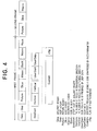
- the input video code comprises, in each layer, a sequence header "Seq", a GOP header "Gop” assigned to each GOP, a picture header "Picture” for identifying each picture, a slice header “Slice” for identifying each slice, a macro block header "Macro” for identifying each macroblock, and a block code "Block”.
- the sequence header "Seq" located at the leading edge of the input video code namely, only at the leading edge of a first frame comprises a sequence header start code "SeqStart", a transversal pixel number code "Horizon” indicative of the number of pixels (horizontal size) after transversal expansion, a longitudinal pixel number code Vertical indicative of the number of pixels (vertical size) after longitudinal expansion, a user data presence code"UserStart” indicative of presence of user data, and a user data area "UserData”.
- the sequence header Seq contains the user data area "UserData" which can be freely defined by a user.
- This embodiment is characterized by arranging in that area an identifier "Custom” of, for example, six bytes indicative of being a code compressed by the use of the fixed parameter, and a fixed parameter flag "cflg" of, for example, two bytes, as illustrated in Fig. 4.
- the above-mentioned fixed parameter flag cflg indicates that the video code is restricted to the I picture and the P picture, when the least significant bit (B0) of the two bytes has a level "1".
- the second bit (B1) counted from the least significant bit of the two bytes has a level "1"
- it is indicated that the video code is a code with the motion compensation value fixed.
- This embodiment has a structure capable of carrying out high-speed reproduction and normal reproduction.
- the device of this embodiment carries out expansion and reproduction of three types of encoded images (video code) including the I picture which is an intraframe encoded image, the P picture which is an interframe encoded image predicted from a time-sequentially preceding frame already encoded, and the B picture which is an interframe encoded image predicted from time-sequentially preceding and succeeding two frames.
- the header analyzing section 11 After judging the picture type of the input video code, the header analyzing section 11 produces a control signal for controlling an addition at the adder 15, although not shown in Fig. 2, to selectively control the addition of output differential values of the forward prediction section 18, the bidirectional prediction section 19, and the backward prediction section 20 to an output of the IDCT section 14.
- Such selective control of the addition at the adder 15 may be carried out by the use of a control signal separately produced from the IDCT section 14.
- the I picture is decoded by the decoding section 12, dequantized by the dequantizing section 13, and subjected to inverse DCT (IDCT) by the IDCT section 14 to calculate the value of the image of each block.
- IDCT inverse DCT
- the video code is expanded into the image which is outputted through the adder 15 as it is and which is supplied to the preceding frame section 16 or the succeeding frame section 17 to be stored therein.
- the header analyzing section 11 analyzes that the input video code is the P picture
- the P picture is decoded by the decoding section 12, dequantized by the dequantizing section 13, subjected to IDCT by the IDCT section 14 to calculate the differential value of each block.
- the differential value is supplied to the adder 15 to be added to a motion compensated block obtained by motion compensating, by the forward prediction section 18, the video code of the preceding frame stored in the preceding frame section 16.
- the video code is expanded into the original image which is outputted and which is supplied to the preceding frame section 16 or the succeeding frame section 17 to be stored therein.
- the header analyzing section 11 analyzes that the input video code is the B picture
- the B picture is decoded by the decoding section 12, dequantized by the dequantizing section 13, subjected to IDCT by the IDCT section 14 to calculate the differential value of each block.
- the differential value is supplied to the adder 15 to be added either to a motion compensated block obtained by motion compensating, by the bidirectional prediction section 19, the video code of the preceding/succeeding frame stored in the preceding frame section 16 or the succeeding frame section 17 or to a motion compensated block obtained by motion compensating, by the forward prediction section 18, the video code of the preceding frame stored in the preceding frame section 16 and a motion compensated block obtained by motion compensating, by the backward prediction section 20, the video code of the succeeding frame stored in the succeeding frame section 17.
- the video code is expanded into the original image which is outputted and which is supplied to the preceding frame section 16 or the succeeding frame section 17 to be stored therein.
- the header analyzing section 11 for reading the input video code to carry out header analysis detects whether or not the user data "UserData" in the sequence header "Seq" contain the identifier "Custom". In presence of the identifier "Custom”, high-speed reproduction is carried out.
- processing is carried out assuming that the picture structure is fixed to the I picture and the P picture and that the motion compensation value is fixed.
- the I picture is decoded by the decoding section 12, dequantized by the dequantizing section 13, and subjected to IDCT by the IDCT section 14 to calculate the value of the pixels in each block.
- IDCT IDCT section 14
- the P picture is decoded by the decoding section 12, dequantized by the dequantizing section 13, and subjected to IDCT by the IDCT section 14 to calculate the differential value of each block.
- the differential value is added by the adder 15 to the motion compensated block obtained by motion compensating, by the forward prediction section 18, the video code of the preceding frame stored in the preceding frame section 16.
- the video code is expanded and reproduced into the image.
- MPEG prescribes three types of pictures, namely, the I picture, the P picture, and the B picture.
- the I picture Upon reproduction of the input video code, it is unnecessary, for the I picture, to refer to the image of the preceding or the succeeding frame because it is an intraframe encoded image.
- the P picture requires forward prediction with reference to the image of the preceding picture.
- the B picture requires backward prediction or bidirectional prediction with reference to the image of the preceding frame or the image of the succeeding frame. Accordingly, the B picture code requires a long processing time as compared with the I picture code or the P picture code.
- the input video code comprises an I picture, a B picture, a B picture, and a P picture in this order from the first frame to the fourth frame as illustrated in Fig. 5(A).
- the first frame requires no reference frame because it is the I picture.
- backward prediction or the bidirectional prediction is carried out with reference to the image of the I picture in the first frame as a preceding frame and to the image of the P picture in the fourth frame as a succeeding frame, as schematically depicted at 41 to 44.
- the fourth frame which is the P picture
- forward prediction is carried out with reference to the image of the I picture in the first frame as a preceding frame. This case requires a long time to process the B picture and is not adapted to high-speed reproduction.
- the input video code is fixed to the I picture and the P picture alone and comprises, for example, an I picture in the first frame and P pictures in the second through the fourth frames, as illustrated in Fig. 5(B).
- no reference frame is required for the first frame because it is the I picture.
- forward prediction alone is carried out with reference to the image of the I picture or the P picture of one frame before, as schematically depicted at 46, 47, and 48 in Fig. 5(B). This case dispenses with processing of the B picture and is adapted to high-speed reproduction.
- the header analyzing section 11 in Fig. 2 reads the type of the picture from the picture header ("Picture" in Fig. 4) in the input video code (step 51) and judges whether or not it is the I picture (step 52). In case of the I picture, the above-mentioned processing of the I picture is carried out by the decoding section 12, the dequantizing section 13, and the IDCT section 14 illustrated in Fig. 2 to perform expansion and reproduction (step 53).
- the header analyzing section 11 judges whether or not it is the P picture (step 54). In case of the P picture, the processing of the P picture is carried out (step 55). If it is not the P picture, the processing of the B picture is carried out judging that it is the B picture (step 56).
- the above-mentioned processing of the P picture is carried out by the decoding section 12, the dequantizing section 13, the IDCT section 14, the adder 15, the preceding frame section 16, the succeeding frame section 17, and the forward prediction section 18 illustrated in Fig. 2 in the manner described in the foregoing.
- the processing of the B picture is carried out by the use of the bidirectional prediction section 19 and the backward prediction section 20 in addition.
- the header analyzing section 11 illustrated in Fig. 2 detects presence of the fixed parameter identifier "Custom" from the sequence header ("Seq" in Fig. 4) in the input video code, reads the type of the picture from the picture header ("Picture” in Fig. 4), and judges whether or not it is the I picture (step 52).
- the above-mentioned processing of the I picture is carried out by the decoding section 12, the dequantizing section 13, and the IDCT section 14 illustrated in Fig. 2 to perform expansion and reproduction (step 53).
- the header analyzing section 11 judges that the picture is the P picture because the input video code has the fixed parameter. Like the step 55, the processing of the P picture is carried out (step 58).
- the encoding format itself is similar to that of MPEG so that compatibility with MPEG is assured.
- the header analyzing section 11 adds "1" to a variable i having an initial value of zero upon detection of the sequence header (step 61). Subsequently, judgement is made whether or not the variable i is greater than a key frame rate (step 62).
- the key frame rate is the number of frames indicating a fixed transmission interval of a single picture.
- step 65 the processing of the P picture is carried out (step 65). Specifically, the motion compensated block obtained by motion compensating, by the forward prediction section 18, the video code of the preceding frame stored in the preceding frame section 16 is added by the adder 15 to the differential value obtained by the above-mentioned decoding section 12, the dequantizing section 13, and the IDCT section 14 to thereby carry out expansion and reproduction of the image.
- the P picture requires a reference to the image of the preceding picture.
- the I picture does not need any reference to the image of the preceding picture.
- the first frame always comprises the I picture.
- the interval (key frame rate) of the I picture is fixed.
- the processing of the I picture is carried out by the decoding section 12, the dequantizing section 13, and the IDCT section 14 (step 63). After completion of the processing of the I picture, the above-mentioned variable is reset to zero to prepare for the next processing (step 64).
- motion compensation is contained in the P picture or the B picture code.
- a position of a reference block can be displaced.
- the image is segmented into small blocks. Each block is searched to find a particular block at which a difference is smallest between the current frame and the preceding frame of one frame before or preceding and succeeding two frames. Then, motion compensation is carried out. Calculation is made of a difference between each block in the current frame and the motion compensated block to obtain a differential block.
- the differential block is subjected to DCT and the result of transform is quantized to obtain the P picture or the B picture which is a high-efficiency encoded interframe code.
- Fig. 8(A) shows a case where the motion compensation is not fixed.
- Fig. 8(B) shows a case where the motion compensation is fixed to (0, 0) (no motion compensation).
- a block P of the preceding frame is motion compensated by (dx, dy) into a motion compensated block P' which is referenced and added to a differential block D to be stored in a block Q of the current frame.
- Fig. 8(B) shows that the block P of the preceding frame is referenced and added to the differential block D to be stored in the block Q of the current frame.
- each of variables y and x is at first set to an initial value of zero (steps 70, 71). Subsequently, a motion compensation code of the block is expanded by the forward prediction section 18 (step 72). The motion compensation value is stored in the variables dx and dy (step 73).
- a differential value code of the block is expanded by the forward prediction section 18 (step 74).
- the position of the reference block is calculated from the expanded motion compensation in accordance with the following formulas (step 75).
- the forward prediction section 18 extracts from the preceding frame section 16 a particular block at the position calculated in the above-mentioned step 75 (step 76).
- the particular block is written in a buffer of the current frame (step 78).
- "8" is added to the variable x (step 79).
- Judgement is made whether or not the variable x after addition is greater than the horizontal size ("Horizon" in Fig. 4) analyzed from the sequence header "Seq" (step 80).
- the video data of the current frame are delivered from the adder 15 to a display section, which is not illustrated in the figures, to be displayed (step 83). Then, the video data of the current frame delivered from the adder 15 are stored in the preceding frame section 16 (step 84).
- each of the variables y and x is set to an initial value of zero (steps 70, 71). Subsequently, the motion compensation code of the block is skipped (step 91).
- the differential value code of the block is expanded by the forward prediction section 21 (step 92).
- the forward prediction section 21 extracts from the preceding frame section 16 a particular block at the position (x, y) represented by the variables x and y (step 93).
- the above-mentioned expanded differential value is added to the particular block as extracted (step 77).
- the block is written in the buffer of the current frame (step 78).
- "8" is added to the variable x (step 79).
- Judgement is made whether or not the variable x after addition is greater than the horizontal size (step 80).
- the video data of the current frame are delivered from the adder 15 to the display section, which is not illustrated in the figure, to be displayed (step 83). Thereafter, the video data of the current frame delivered from the adder 15 are stored in the preceding frame section 16 (step 84).
- the motion compensation has a value (0, 0).
- the fixed value such as (2, 2), (-1, 0), and (0, 5)
- the positions of the reference blocks of the preceding frame are given by (x+2, y+2), (x-1, y), (x, y+5).
- each reference block is adjacent so that it is unnecessary to calculate the reference position for every block.
- a code can be formed by the I picture which is an intraframe encoded image and the P picture which is an interframe encoded image.
- the differential value is small, no significant change is visible even if the image of the P picture is not displayed. Accordingly, it is possible to increase the processing speed by saving the time for display of the image of the P picture in that period.
- Fig. 11(A) is a view for describing the processing in case where the display of every P picture is renewed.
- Fig. 11(B) is a view for describing the processing in case where the display of the P picture is not renewed until a predetermined condition is satisfied.
- CODE represents the input video code supplied to the reproducing device.
- I and P represent the I picture and the P picture, respectively.
- Numerals indicate the orders of the frames.
- DISPLAY indicates the picture displayed by the display section.
- TOTAL DIFFERENTIAL VALUE below “DISPLAY” indicates a total sum of the differential values per one frame.
- Fig. 11(A) the code as displayed coincides with the input video code. Every input video code is displayed irrespective of the total differential values.
- dotted rectangles illustrated in the column of "DISPLAY" in Fig. 11(B) indicate that no renewal of display is carried out. Such non-renewal of display is achieved by continuously displaying the preceding frame until the cumulative value of the total differential values per one frame exceeds a predetermined threshold value (herein, "54").
- the second frame comprises the P picture and has the total differential value equal to "28" which is smaller than the threshold value "54". Accordingly, display of the P picture is not carried out but the I picture of one frame before is displayed.
- the fourth frame also comprises the P picture and has the total differential value equal to "15".
- the fifth frame also comprises the P picture.
- the total differential value and the cumulative value thereof are equal to "43" which is smaller than the threshold value "54". Accordingly, display of the P picture P5 in the fifth frame is not carried out but the P picture P4 of one frame before is displayed. As will be understood from the foregoing description, the P picture P6 in the sixth frame is displayed because the cumulative value of the total differential value exceeds the threshold value "54" (display is renewed).
- the header analyzing unit 11 in Fig. 2 reads the picture type from the picture header ("Picture" in Fig. 4) in the input video code (step 111) and judges whether or not it is the I picture (step 112).
- the processing of the I picture is carried out by the decoding section 12, the dequantizing section 13, and the IDCT section 14 illustrated in Fig. 2 to carry out expansion and reproduction (step 113).
- the video data expanded and reproduced are supplied through the adder 15 to the display section, which is not illustrated in the figure, to be displayed (step 114).
- the video data of the I picture after expansion are delivered from the adder 15 to the preceding frame section 16 to be stored therein (step 115).
- the header analyzing section 11 judges that it is the P picture.
- the differential value is expanded by the above-mentioned decoding section 12, the dequantizing section 13, and the IDCT section 14 (step 116) and added by the adder 15 to the motion compensated block obtained by motion compensating, by the forward prediction section 18, the video code of the preceding frame stored in the preceding frame section 16 (step 117).
- the image of the P picture is expanded and reproduced, and supplied to the display section to be displayed (step 118).
- the expanded video data extracted from the adder 15 are stored in the preceding frame section 16 (step 119).
- the header analyzing section 11 in Fig. 2 reads the picture type from the picture header ("Picture" in Fig. 4) in the input video code (step 111).
- picture is detected to be the I picture
- operation is similar to Fig. 12 (steps 112-115).
- the renewal of display of the I picture is carried out at every time.
- the header analyzing section 11 judges that it is the P picture.
- the image of the P picture is expanded and reproduced by the above-mentioned decoding section 12, the dequantizing section 13, the IDCT section 14, and the adder 15 (steps 116, 117).
- the forward prediction section 21 in Fig. 2 makes an internal adder 22 add, to a variable m having an initial value of zero, the total differential value of the P picture supplied from the IDCT section 14 (step 121). Judgement is made whether or not the value of the variable m, namely, the cumulative value of the total differential values is greater than a predetermined threshold value (step 122).
- the expanded image of the P picture produced from the adder 22 is supplied to the preceding frame section 16 (step 125). Accordingly, in this case, a display memory in the display section not illustrated in Fig. 2 is not rewritten by the output video data of the adder 22.
- the display section continuously displays the video data of the preceding frame stored in the display memory.
- the forward prediction section 21 in Fig. 2 judges in the step 122 that the variable m is greater than the threshold value
- the motion compensated block obtained by motion compensating, by the forward prediction section 21, the video code of the preceding frame stored in the preceding frame section 16 is delivered to the adder 22.
- the motion compensated block is added to the expanded differential value from the IDCT section 14 to obtain the expanded video data of the P picture.
- the expanded video data are supplied to the display memory of the display section to renew the content of the display memory so that the video display is renewed (step 123).
- the forward prediction section 21 resets the variable m to zero (step 124). Then, the expanded video data of the P picture extracted from the adder 22 are stored in the preceding frame section 16 (step 125).
- renewal of the display is not carried out until the cumulative value of the total differential values between frames exceeds the threshold value. Accordingly, it is possible to reduce the number of processing times for display of the image. As a consequence, high-speed processing can be carried out.
- this embodiment is adapted to high-speed reproduction.
- the processing upon transmission of the I picture and the P picture alone with the interframe encoded image fixed to the P picture, the processing with motion compensation fixed, and display renewal/non-renewal processing may be carried out independently or in combination of two or all of them.
- expansion processing is carried out after identifying the fixed parameter contained in the input video code. Since the type of the interframe encoded image in the input video code can be specified, it is possible to dispense with the processing for the unsupplied unnecessary interframe encoded image or the motion compensation processing. As a result, the expansion processing can be carried out at a high speed so that high-speed reproduction is performed.
- the input video code itself is identical with that of the international standard encoding system. Therefore, an international standard image reproducing device can be used. As a result, a specific image reproducing device is unnecessary.
- the image reproducing device of the present invention it is possible to dispense with judgement of the type of the interframe encoded image and expansion of the interframe encoded image both in the forward and the backward directions. As a consequence, expansion is carried out at a high speed so as to enable high-speed reproduction.
- the transmission interval of the intraframe encoded image is constant. Since the type of the encoded image can be judged from the frame interval without relying upon the header, the processing time for expansion can be shortened.
- expansion of the input video code is carried out with the motion compensation processing omitted.
- the processing time for motion compensation is unnecessary. Accordingly, expansion can be carried out at a high speed so as to enable high-speed reproduction.
- the image of the preceding frame is continuously displayed until the cumulative value exceeds the threshold value.
- the time required to display the interframe encoded image in that period is saved. Accordingly, expansion processing can be carried out at a high speed so as to enable high-speed reproduction.
- Fig. 14 is a block diagram of an image reproducing device according to the second embodiment of this invention.
- the image reproducing device in Fig. 14 comprises a header analyzing section 211, a VLD section 212, a Q -1 section 213, an inverse DCT section 214, a preceding frame section 215, a succeeding frame section 216, a forward prediction section 217, a bidirectional prediction section 218, and a backward prediction section 219.
- the header analyzing section 211 comprises a sequence header analyzing unit 224, a GOP header analyzing unit 225, a picture header analyzing unit 226, and a slice header analyzing unit 227.
- the image reproducing device reads a code and the header analyzing section 211 carries out header analysis. At this time, judgement is made whether or not the code has a fixed parameter. If affirmative, high-speed reproduction is carried out. In case of high-speed reproduction, it is assumed that the I picture alone is contained, a slice width is fixed, and an escape code alone is contained.
- a VLD2 section 220 decodes a high-efficiency compressed code.
- a Q2 -1 section 221 carries out dequantization.
- An inverse DCT2 section 222 carries out inverse DCT.
- An enlarging section 223 enlarges and displays a reproduced image. Unless high-speed reproduction is performed, expansion is carried out of three types of codes, namely, the I picture which is an intraframe code, the P picture which is an interframe code in a forward direction alone, and the B picture which is an interframe code both in forward and backward directions.
- the VLD section 212 carries out decoding.
- the Q -1 section 213 carries out dequantization.
- the inverse DCT section 214 carries out inverse DCT to calculate pixel values in a block.
- video expansion is carried out.
- the VLD section 212 carries out decoding.
- the Q -1 section 213 carries out dequantization.
- the inverse DCT section 214 carries out inverse DCT to calculate a differential value of the block.
- the forward prediction section 217 adds the differential value to a motion compensated block of a preceding frame stored in the preceding frame section 215.
- video expansion is carried out.
- the VLD section 212 carries out decoding.
- the Q -1 section 213 carries out dequantization.
- the inverse DCT section 214 carries out inverse DCT to calculate a differential value of the block.
- the bidirectional prediction section 218 or the backward prediction section 219 adds the differential value to a motion compensated block of a preceding frame stored in the preceding frame section 215 and to a motion compensated block of a succeeding frame stored in the succeeding frame section 216.
- video expansion is carried out.
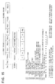
- Fig. 15 shows a structure of a code format according to MPEG, which is similar to that mentioned with reference to Fig. 4.
- the MPEG code comprises, for each layer, (1) a sequence header, (2) a GOP (Group of Pictures) header, (3) a picture header, (4) a slice header, (5) a macroblock header, and (6) a code of a block, as illustrated in Fig. 15.
- the sequence header has a user data area, as represented by "UserData” (11), which can be freely defined by a user.
- a flag indicating that a parameter is fixed is stored.
- the user data (11) comprise an identifier "Custom” (12) indicating that the code is compressed by the use of a fixed parameter, and a flag (13) of the fixed parameter.
- the flag (13) of the fixed parameter comprises 1) a bit indicating enlargement to be carried out upon expansion, 2) a bit indicating that the picture structure is fixed to the I picture alone, 3) a bit indicating that the slice width is fixed to a picture size, 4) a bit indicating cut-off of high-frequency components, and 5) a bit indicating that the code type is fixed to an escape code alone.
- Fig. 16 is a view for describing enlargement by the image reproducing device.
- Fig. 16 shows a case where an image of 2 x 2 pixels is enlarged twice in a longitudinal direction and twice in a transversal direction.
- Fig. 16(A) shows each pixel value of 2 x 2 pixels.
- Fig. 16(C) shows each pixel value of 4 x 4 pixels after enlargement of twice in a longitudinal direction and twice in a transversal direction.
- Fig. 16(B) shows processing of transforming one pixel into four pixels. In the case illustrated in Fig.
- a single pixel is extracted from (A) and transformed into four pixels as shown in (B) to be written in an image (C) after enlarged twice in a longitudinal direction and twice in a transversal direction.
- an upper right pixel (29) in (A) is subjected to transform in (B) into P1(29), P2(29), P3(29), and P4(29) which are written in a corresponding area in (C).
- modification (dither processing) of the pixel values to improve a picture quality is not carried out upon enlargement of twice in a longitudinal direction and twice in a transversal direction.
- dither processing may be carried out.
- magnification is twice in a longitudinal direction and twice in a transversal direction in this description, another integral multiple such as three times or more may be used.
- an expansion time can be shortened. For example, in case of enlargement of twice in a longitudinal direction and twice in a transversal direction, the expansion time is shortened to 1/4.
- expansion processing includes not only memory read/write operations but also multiplications in inverse DCT and in dequantization and bit shift operations in decoding of variable length codes.
- the memory read/write operations impose less load upon a CPU as compared with the multiplications or the bit shift operations. Even if such enlargement processing is included, processing is carried out at a higher speed in case where enlargement is carried out than in case where no enlargement is carried out.
- Fig. 18 is a view for describing processing in case where a picture structure is fixed.
- Fig. 18(A) shows a picture structure comprising an I picture, a P picture, and a B picture.
- Fig. 18(B) shows a picture structure fixed to the I picture alone.
- the P picture it is necessary to carry out forward prediction with reference to an image of a preceding picture.
- the B picture it is necessary to carry out backward prediction or bidirectional prediction with reference to an image of a preceding frame or an image of a succeeding frame.
- the processing time is long as compared with the case of the I picture.
- Fig. 18(A) shows a picture structure comprising an I picture, a P picture, and a B picture.
- a first frame comprises the I picture and no reference frame is required.
- a second frame and a third frame comprise B pictures.
- backward prediction or bidirectional prediction is carried out.
- the fourth frame comprises the P picture.
- forward prediction is carried out.
- all of the first through the fourth frames comprise I pictures. It is therefore unnecessary to carry out forward prediction, backward prediction, or bidirectional prediction.
- Fig. 19 is a flow chart for describing an operation of Fig. 18.
- Fig. 19(A) shows processing of the picture structure comprising the I picture, the P picture, and the B picture.
- Fig. 19(B) shows processing of the picture structure fixed to the I picture alone.
- Fig. 19(C) shows judgement whether (A) or (B) is to be processed.
- picture processing 1 illustrated in Fig. 19(A) the type of a picture is read from a picture header (step 310). Judgement is made of the type of the picture (step 311). In case of the I picture, processing of the I picture is carried out (step 312). In case of the P picture, processing of the P picture is carried out (step 313).
- processing of the B picture is carried out (step 314).
- picture processing 2 illustrated in Fig. 19(B) processing of the I picture is carried out (step 315).
- picture header analysis illustrated in Fig. 19(C) judgement is made whether or not a parameter is fixed (step 316). If negative, the picture processing 1 is carried out (step 317). If affirmative, the picture processing 2 is carried out (step 318).
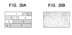
- Fig. 20 is a view for describing processing in case where the slice width is fixed.
- MPEG an image of a single frame is segmented into several areas of 16 x 16 pixels as a unit.
- a slice header is inserted at the leading edge of a code in each segmented area to indicate which area of the image it is.
- Fig. 20(A) shows a case where the slice width is not fixed.
- Fig. 20(B) shows a case where the slice width is fixed to a picture size.
- the image is segmented into five areas (1-5).
- the slice header is inserted at the leading edge of the code in each of the areas 1 to 5.
- the slice width is fixed to the picture size and no segmentation is carried out. Accordingly, only one slice header is present.
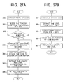
- Fig. 21 is a flow chart for describing an operation of Fig. 20.
- Fig. 21(A) shows processing in case where the slice width is not fixed.
- Fig. 21(B) shows processing in case where the slice width is fixed to the picture size.
- Fig. 21(C) shows judgement whether (A) or (B) is to be processed.
- slice processing 1 illustrated in Fig. 21(A) the slice header is read (step 320).
- Processing of macroblocks is carried out (step 321).
- Judgement is made whether or not a next header is a slice header (step 322). If affirmative, the operation returns to the step 320. If not, judgement is made whether or not processing of all macroblocks has been completed (step 323). If not, the operation returns to the step 321.
- slice processing 2 illustrated in Fig. 21(B) the slice header is read (step 324). Processing of macroblocks is carried out (step 325). Judgement is made whether or not processing of all macroblocks has been completed (step 326). If not, the operation returns to the step 324. If affirmative, the operation comes to an end.
- slice header analysis illustrated in Fig. 21(C) judgement is made whether or not the parameter is fixed (step 327). If not, the slice processing 1 is carried out (step 328). If affirmative, the slice processing 2 is carried out (step 329).
- Fig. 22 is a view for describing processing in case where inverse DCT is carried out assuming that high frequency components are equal to zero.
- Fig. 22(A) shows a case where the high frequency components are not assumed to be zero.
- Fig. 22(B) shows a case where the high frequency components are assumed to be zero.
- Fig. 22(A) shows a scanning order (zigzag scanning) of frequency components of an 8 x 8 block from a low frequency to a high frequency.
- Fig. 22(B) also shows zigzag scanning. However, the twenty-second and subsequent high frequency components are all assumed to be zero. In case of a natural image, video information concentrates to the low frequency components. Accordingly, significant deterioration of the picture quality is not observed even if the high frequency components are assumed to be zero.
- Fig. 23 is a flow chart for describing an operation in case where inverse DCT is carried out without assuming that the high frequency components are equal to zero.
- zero is stored in a variable y (step 330).
- Zero is stored in a variable v (step 331).
- Zero is stored in a variable dd (step 332).
- Zero is stored in a variable u (step 333).
- a product of a buffer Buffer(y, u) of an 8 x 8 block to be subjected to inverse DCT and an inverse DCT coefficient cos((2v+1)u ⁇ )/2 is added to the variable dd (step 334).
- unity is added to the variable u (step 335).
- step 336 judges whether or not the value of the variable u is smaller than eight. If affirmative, the operation returns to the step 334. If not, the value of the variable dd is stored in a temporary storage buffer t(v, y) (step 337). Then, unity is added to the variable v (step 338). Judgement is made whether or not the value of the variable v is smaller than eight (step 339). If affirmative, the operation returns to the step 332. Next, unity is added to the variable y (step 340). Judgement is made whether or not the variable y is smaller than eight (step 341). If affirmative, the operation returns to the step 331. If not, zero is stored in the variable y (step 342).
- variable x zero is stored in the variable x (step 343).
- zero is stored in the variable dd (step 344).
- Zero is stored in the variable u (step 345).
- a product of t(y, u) and cos((2x + 1)u ⁇ )/2 is added to the variable dd (step 346).
- unity is added to the variable u (step 347).
- Judgement is made whether or not the value of the variable u is smaller than eight (step 348). If affirmative, the operation returns to the step 346. If not, the value of the variable dd is stored in Buffer(x, y) (step 349). Then, unity is added to the variable x (step 350).
- step 351 Judgement is made whether or not the value of the variable x is smaller than eight (step 351). If affirmative, the operation returns to the step 344. Next, unity is added to the variable y (step 352). Judgement is made whether or not the value of the variable y is smaller than eight (step 353). If affirmative, the operation returns to the step 344. If not, the operation comes to an end.
- Fig. 24 is a flow chart for describing an operation in case where inverse DCT is carried out assuming that the high frequency components are equal to zero.
- Fig. 24 shows an example in which the twenty-second and subsequent frequency components are assumed to be zero.
- inverse DCT 2 illustrated in Fig. 24 zero is stored in the variable y (step 360).
- Zero is stored in the variable v (step 361).
- Zero is stored in the variable dd (step 362).
- Zero is stored in the variable u (step 363).
- a product of the buffer Buffer(y, u) of an 8 x 8 block to be subjected to inverse DCT and the inverse DCT coefficient cos((2v + 1)u ⁇ )/2 is added to the variable dd (step 364).
- step 365 unity is added to the variable u (step 365). Judgement is made whether or not the value of the variable u is smaller than the value of umax(y) (step 366). If affirmative, the operation returns to the step 364. If not, the value of the variable dd is stored in the temporary storage buffer t(v, y) (step 367). Next, unity is added to the variable v (step 368). Judgement is made whether or not the value of the variable v is smaller than eight (step 369). If affirmative, the operation returns to the step 362. Then, unity is added to the variable y (step 370). Judgement is made whether or not the value of the variable y is smaller than six (step 371). If affirmative, the operation returns to the step 361.
- step 372 If not, zero is stored in the variable y (step 372). Next, zero is stored in the variable x (step 373). Zero is stored in the variable dd (step 374). Zero is stored in the variable u (step 375). Then, a product of t(y, u) and cos((2x + 1)u ⁇ )/2 is added to the variable dd (step 376). Subsequently, unity is added to the variable u (step 377). Judgement is made whether or not the value of the variable u is smaller than six (step 378). If affirmative, the operation returns to the step 376. If not, the value of the variable dd is stored in Buffer(x, y) (step 379).
- step 380 unity is added to the variable x (step 380). Judgement is made whether or not the value of the variable x is smaller than eight (step 381). If affirmative, the operation returns to the step 374. Next, unity is added to the variable y (step 382). Judgement is made whether or not the variable y is smaller than eight (step 383). If affirmative, the operation returns to the step 374. If not, the operation comes to an end.
- any value between 1 and 64 may be selected in dependence upon the processing ability of the reproducing unit.
- Fig. 25 shows a structure of an escape code.
- MPEG prescribes the escape code of a fixed pitch length.
- the escape code comprises (1) a code (000001) indicative of being the escape code, (2) a run length (the number of invalid coefficients), and (3) a level (the value of an effective coefficient: -128 to +128).
- Fig. 26 is a table showing examples of an ordinary code and the escape code. As illustrated in Fig. 26, the ordinary codes have a variable length between 2 and 17 bits. On the other hand, all escape codes have a fixed length of 20 bits.
- Fig. 27 is a flow chart for describing an operation of VLD.
- Fig. 27(A) shows processing of the ordinary code.
- Fig. 27(B) shows processing in case where the type of the code is fixed to the escape code alone.
- VLD illustrated in Fig. 27(A) eight bits are picked up from the code (step 390). From the values of the eight bits, judgement is made of the type of the code (step 391). Judgement is made whether or not the code consists of eight or less number of bits (step 392). If affirmative, the operation proceeds to a step 394. If not, an additional number of bits as required are picked up (step 393). The number of bits of the code is added to a pointer of a code buffer (step 394).
- the run length and the level corresponding to the code are picked up (step 395).
- the run length and the level are returned (step 396).
- eight bits are picked up from the code (step 397).
- the level is extracted from the bit 0 through the bit 7 (step 398).
- the run length is extracted from the bit 8 through the bit 13 (step 399).
- Twenty bits are added to the pointer of the code buffer (step 400).
- the run length and the level are returned (step 401).
- the processing upon transmission of both the I picture and the P picture may alternatively be fixed to only the P picture.
- the processing with picture structure fixed, the processing with motion compensation fixed,and display renewal/non-renewal processing may be carried out independently or in combination of two or all of them.
Landscapes
- Engineering & Computer Science (AREA)
- Multimedia (AREA)
- Signal Processing (AREA)
- Compression Or Coding Systems Of Tv Signals (AREA)
Abstract

Description
- This invention relates to an image transmission system and an image reproducing device and, in particular, to a transmission system for transmitting a video code compressed and encoded by the use of discrete cosine transform (DCT) as orthogonal transform and an image reproducing device for reproducing such an encoded image.
- When a video signal is digitized and recorded in a recording medium such as a CD-ROM, a hard disk, and a magnetic tape, the video signal is generally compressed and encoded to be recorded because the amount of data is enormously large.
- Proposals have been made of various compression encoding systems. Among those, use is frequently made of transform encoding by the use of orthogonal transform which efficiently utilizes correlation within a two-dimensional space of an image. Specifically, encoding systems based on the DCT as orthogonal transform are adopted in international standard encoding systems such as a color still image standard JPEG (Joint Photographic Expert Group) and a moving picture encoding standard for storage media (MPEG: Moving Pictures Expert Group).
- In MPEG, one sequence of a moving image is divided into groups of pictures (GOP), each group comprising a plurality of frames (pictures), to be subjected to encoding, as will later be described. The GOP comprises three types of pictures including an I picture which is an intraframe encoded image, a P picture which is an interframe encoded image predicted from a time sequentially preceding frame already encoded, and a B picture which is an interframe encoded picture predicted from time sequentially preceding and succeeding two frames.
- A video code according to MPEG can be reproduced by any reproducing unit based on MPEG which is an international standard. However, processing carried out in the decoding unit and the IDCT unit imposes a heavy load upon a central processing unit (CPU). Therefore, high-speed reproduction can not be carried out unless a CPU operable at a high speed is used.
- For example, when a JPEG- or MPEG-based video code reproducing device processes 15 frames per second, reproduction of a single frame must be carried out in about 66 milliseconds. It is assumed here that decoding of the Huffman code requires 30 ms, dequantization requires 10 ms, IDCT by the IDCT unit requires 20 ms, and display requires 20 ms. In this event, a total processing time of 80 ms is required. As a result, a delay of 14 ms is produced upon reproduction of an image of a single frame.
- In order to reduce the load imposed upon the CPU, various proposals have been made in which the encoding system is partially modified so that high-speed reproduction can be carried out even with a low-speed CPU. For example, such proposals have been made in Japanese Patent Publications JP-A 241270/1990, JP-A 971/1992, JP-A 256452/1991, JP-A 357788/1992, and JP-A 299688/1992.
- However, each of the conventional image reproducing devices and encoding systems mentioned in the above-referenced publications carries out image compression by partially modifying the encoding system and is not compatible with the international standard encoding systems. Therefore, a specific reproducing unit is required.
- In the conventional image compression by reducing the amount of the compressed video codes, it is necessary to judge an optimum compression method for every block. Accordingly, preparation of the compressed codes requires a long time. In addition, the amount of the codes does not correspond to the processing ability of the image reproducing device. Accordingly, realtime reproduction is impossible by a reproducing device having a low processing speed. On the other hand, even with a high-speed reproducing device, no other than those codes having a predetermined picture quality can be reproduced because the amount of the compressed codes is determined.
- It is therefore an object of this invention to provide an image transmission system and an image reproducing device which have a simple structure but are capable of reproducing a DCT-based code at a high speed with deterioration of picture quality suppressed as much as possible in correspondence the ability of the reproducing device.
- Other objects will become clear as the description proceeds.
- According to an aspect of this invention, there is provided an image transmission system comprising:
- preparing means for preparing an intraframe encoded image by segmenting an image into a plurality of blocks and by compressing and encoding each block by the use of discrete cosine transform;
- preparing means for preparing an interframe encoded image by searching for a particular block at which a difference is smallest between a current frame and either a preceding frame or both preceding and succeeding frames in a time sequential order, by carrying out motion compensation on said each block, and by compressing and encoding a differential value between each block of said current frame and a motion compensated block by the use of discrete cosine transform;
- multiplexing and transmitting means for multiplexing and transmitting said intraframe encoded image and said interframe encoded image together with a header;
- transmitting means for transmitting an identifier for identifying at least one of fixed parameters including a type of said interframe encoded image to be transmitted with said intraframe encoded image and a motion compensation value fixed as said fixed parameters which are transmitted to a reproducing side together with said header; and
- expansion processing means for carrying out expansion processing after detecting said identifier in said header to thereby identify said fixed parameter of an input video code.
-
- According to another aspect of this invention, there is provided an image reproducing device comprising:
- expanding and reproducing means for expanding and reproducing a video code comprising an intraframe encoded image and an interframe encoded image which are multiplexed together with a header having a fixed parameter identifier, said intraframe encoded image being prepared by segmenting an image into a plurality of blocks and by compressing and encoding each block by the use of discrete cosine transform, said interframe encoded image being prepared by searching for a particular block at which a difference is smallest between a current frame and a preceding frame in a time sequential order, by carrying out motion compensation on said each block, and by compressing and encoding a differential value between each block of said current frame and a motion compensated block by the use of discrete cosine transform;
- header analyzing means for judging, with reference to said header contained in said video code supplied as an input video code, whether or not said input video code exclusively comprises said intraframe encoded image and said interframe encoded image with a type of said interframe encoded image fixed; and
- expansion processing means for detecting whether or not said input video code is said intraframe encoded image when said header analyzing means judges that said input video code is such a code that the type of said interframe encoded image is fixed, for carrying out expansion processing of said intraframe encoded image when it is detected that said input video code is said intraframe encoded image, and for carrying out expansion processing of said interframe encoded image when it is detected that said input video code is not said intraframe encoded image.
-
- According to still another aspect of this invention, there is provided an image reproducing device comprising:
- reproducing means for reproducing a moving image compressed and encoded by the use of a high-efficiency encoded intraframe code and a high-efficiency encoded interframe code, said intraframe code being prepared by segmenting said image into small blocks, by carrying out discrete cosine transform on each block, and by quantizing a result of said transform, said interframe code being prepared by segmenting said image into small blocks, by searching for a particular block at which a difference is smallest between a current frame and preceding and succeeding frames, by carrying out motion compensation on each block, by calculating a difference between each block of the current frame and each block of a motion compensated frame, by carrying out discrete cosine transform on a differential block, and by quantizing a result of said transform; and
- judging means for judging whether or not a code has a fixed parameter by analyzing said code.
- Fig. 1 is a block diagram of one example of a conventional image reproducing device;
- Fig. 2 is a block diagram of an image reproducing device according to a first embodiment of this invention;
- Fig. 3(A) shows a video sequence of a moving image in a hierarchical structure of an MPEG code format;
- Fig. 3(B) shows a group of pictures of the moving image in the hierarchical structure of the MPEG code format;
- Fig. 3(C) shows a picture of the moving image in the hierarchical structure of the MPEG code format;
- Fig. 3(D) shows a slice of the moving image in the hierarchical structure of the MPEG code format;
- Fig. 3(E) shows a macroblock of the moving image in the hierarchical structure of the MPEG code format;
- Fig. 3(F) shows a block of the moving image in the hierarchical structure of the MPEG code format;
- Fig. 4 is a view for illustrating a structure of an MPEG-based code format in relation to the first embodiment of this invention;
- Fig. 5(A) is a view for describing a processing in the image reproducing device in case where a picture structure is not fixed, assuming that the input video code comprises an I picture, a B picture, a B picture, and a P picture in this order from the first to the fourth frames;
- Fig. 5(B) is a view for describing a processing in the image reproducing device in case where a picture structure is fixed, assuming that the input video code comprises an. I picture in the first frame and P pictures in the second through the fourth frames;
- Fig. 6(A) is a flow chart for describing an operation of the image reproducing device illustrated in Fig. 2, which is based on a picture structure in accordance with the input video code illustrated in Fig. 5(A);
- Fig. 6(B) is a flow chart for describing an operation of the image reproducing device illustrated in Fig. 2, which is based on a picture structure in accordance with the input video code illustrated in Fig. 5(B);
- Fig. 7 is a flow chart for describing an operation of the image reproducing device illustrated in Fig. 2 in case where a picture interval is fixed;
- Fig. 8(A) is a view for describing a processing in case where motion compensation is not fixed;
- Fig. 8(B) is a view for describing a processing in case where motion compensation is fixed;
- Fig. 9 is a flow chart for describing an operation of Fig. 2 in case where motion compensation is contained;
- Fig. 10 is a flow chart for describing an operation of Fig. 2 in case where no motion compensation is contained;
- Fig. 11(A) is a view for describing a processing in case where the display of every P picture is renewed;
- Fig. 11(B) is a view for describing a processing in case where the display of the P picture is not renewed until a predetermined condition is satisfied;
- Fig. 12 is a flow chart for describing an operation upon renewal of display according to the embodiment of Fig. 2, as illustrated in Fig. 11(A);
- Fig. 13 is a flow chart for describing an operation upon non-renewal of display according to the embodiment of Fig. 2, as illustrated in Fig. 11(B);
- Fig. 14 is a block diagram of a moving image reproducing device according to a second embodiment of this invention;
- Fig. 15 is a view for illustrating a structure of an MPEG-based code format in relation to the second embodiment of this invention;
- Fig. 16(A) shows each pixel value of 2
X 2 pixels for describing enlargement processing according to the second embodiment; - Fig. 16(B) shows processing of transforming one pixel into four pixels for describing enlargement processing according to the second embodiment;
- Fig. 16(C) shows each pixel value of 4
X 4 pixels after enlargement according to the second embodiment; - Fig. 17 is a flow chart illustrating an operation of the enlargement processing according to this invention;
- Fig. 18(A) is a view for describing a processing in the image reproducing device in case where a picture structure is not fixed, assuming that the input video code comprises an I picture, a B picture, a B picture, and a P picture in this order from the first to the fourth frames;
- Fig. 18(B) is a view for describing a processing in the image reproducing device in case where a picture structure is fixed, assuming that the input video code comprises only I pictures in the first through the fourth frames according to the second embodiment;
- Fig. 19(A) is a flow chart illustrating an operation of processing of the picture structure comprising an I picture, a P picture, and a B picture;
- Fig. 19(B) is a flow chart illustrating an operation of processing of the picture structure fixed to the I picture alone;
- Fig. 19(C) is a flow chart illustrating a judgement whether the processing of Fig. 19 (A) or Fig. 19(B) is to be performed;
- Fig. 20(A) is a view for describing processing on condition that a slice width is not fixed;
- Fig. 20(B) is a view for describing processing on condition that a slice width is fixed to a picture size;
- Fig. 21(A) is a flow chart illustrating an operation of slice processing in case where the slice width is not fixed;
- Fig. 21(B) is a flow chart illustrating an operation of slice processing in case where the slice width is fixed to a picture size;
- Fig. 21(C) is a flow chart illustrating a judgement whether the processing of Fig. 21(A) or Fig. 21(B) is to be performed;
- Fig. 22(A) is a view for describing processing on the assumption that high frequency components are not equal to zero;
- Fig. 22(B) is a view for describing processing on the assumption that high frequency components are equal to zero;
- Fig. 23 is a flow chart illustrating an operation of inverse DCT;
- Fig. 24 is a flow chart illustrating an operation of inverse DCT according to the second embodiment;
- Fig. 25 is a view showing a format of an escape code;
- Fig. 26 is a table illustrating examples of an ordinary code and the escape code;
- Fig. 27(A) is a flow chart illustrating an operation of VLD for showing processing of the ordinary code; and
- Fig. 27(B) is a flow chart illustrating an operation of VLD for showing processing in case where the type of the code is fixed to the escape code alone.
-
- Referring to Fig. 1, description is, at first, made about a conventional image reproducing device for a better understanding of this invention.
- Reproduction of a video code according to a conventional DCT-based encoding system will be described in conjunction with MPEG by way of example. Fig. 1 is a block diagram of one example of the conventional image reproducing device. The conventional image reproducing device reads a video code according to MPEG and analyzes a code type and the like by the use of
header analyzing section 131. - When the
header analyzing section 131 analyzes that an input video code is the I picture, a high-efficiency compressed variable-length Huffman code of the I picture is decoded by decodingsection 132, dequantized bydequantizing section 133, and subjected to inverse DCT (IDCT) byIDCT section 134 to calculate a value of an image of each block. The image as expanded is outputted through anadder 135 and supplied to apreceding frame section 136 or a succeedingframe section 137 to be stored therein. - When the
header analyzing section 131 analyzes that the input video code is the P picture, the P picture is decoded by thedecoding section 132, dequantized by thedequantizing section 133, and subjected to IDCT by theIDCT section 134 to calculate a differential value of each block. The differential value is supplied to theadder 135 and added to a motion compensated block obtained by motion-compensating, byforward prediction section 138, a video code of a preceding frame stored in thepreceding frame section 136. Thus, the video code is expanded into an original image which is outputted and which is supplied to thepreceding frame section 136 or the succeedingframe section 137 to be stored therein. - When the
header analyzing section 131 analyzes that the input video code is the B picture, the B picture is decoded by thedecoding section 132, dequantized by thedequantizing section 133, and subjected to IDCT by theIDCT section 134 to calculate a differential value of each block. The differential value is supplied to theadder 135 and added to a motion compensated block obtained by motion-compensating, bybidirectional prediction section 139, a video code of a preceding/succeeding frame stored in thepreceding frame section 136 or the succeedingframe section 137 and to a motion compensated block obtained by motion-compensating, bybackward prediction section 140, a video code of a succeeding frame stored in the succeedingframe section 137. Thus, the video code is expanded into an original image which is outputted and which is supplied to thepreceding frame section 136 or the succeedingframe section 137 to be stored therein. - Thus, a video code according to MPEG can be reproduced by any reproducing device based on MPEG which is an international standard. However, processing carried out in the
decoding section 132 and theIDCT section 134 imposes a heavy load upon a central processing unit (CPU). Therefore, high-speed reproduction can not be carried out unless a CPU operable at a high speed is used. - As mentioned before in the preamble of the instant specification, when a JPEG- or MPEG-based video code reproducing device processes 15 frames per second, reproduction of a single frame must be carried out in about 66 milliseconds. It is assumed here that decoding of the Huffman code requires 30 ms, dequantization requires 10 ms, IDCT by the
IDCT section 134 requires 20 ms, and display requires 20 ms. In this event, a total processing time of 80 ms is required. As a result, a delay of 14 ms is produced upon reproduction of an image of a single frame. - Now, description will proceed to a first embodiment of this invention. Fig. 2 is a block diagram of an image reproducing device according to the first embodiment of this invention.
- As illustrated in Fig. 2, the image reproducing device of this embodiment comprises
header analyzing section 11 for analyzing an input video code, decodingsection 12 for decoding the input video code,dequantizing section 13 for dequantizing decoded video data,IDCT section 14 for carrying out IDCT upon dequantized video data, anadder 15, a precedingframe section 16 for storing video data at a frame time-sequentially one frame earlier with respect to an output of theadder 15, a succeedingframe section 17 for storing video data at a frame time-sequentially one frame later with respect to the output of theadder 15,forward prediction section 18 for carrying out prediction with reference to an output of thepreceding frame section 16,bidirectional prediction section 19 for carrying out prediction with reference to outputs of both thepreceding frame section 16 or the succeedingframe section 17,backward prediction section 20 for carrying out prediction with reference to the output of the succeedingframe section 17,forward prediction section 21, and anadder 22. - The reproducing device illustrated in Fig. 2 carries out reproduction of an input video code according to MPEG. Description will at first be made of a hierarchical structure of a code format of MPEG in conjunction with Fig. 3. In MPEG, a topmost layer is a sequence (video sequence) of a moving image. The sequence comprises a plurality of groups of pictures (GOP) as illustrated in Fig. 3(A). A single GOP comprises a plurality of frames (pictures) as illustrated in Fig. 3(B). The GOP comprises three kinds of pictures including an I picture which is an intraframe encoded image, a P picture which is an interframe encoded image predicted from a time sequentially preceding frame already encoded, and a B picture which is an interframe encoded image predicted from time sequentially preceding and succeeding two frames. As illustrated in Fig. 3(C), each picture comprises a plurality of slices formed by segmenting the picture into desired areas. As illustrated in Fig. 3(D), each slice comprises a plurality of macroblocks arranged from left to right or from top to bottom. As illustrated in Fig. 3(E), a single macroblock comprises six blocks in total, including four adjacent luminance component blocks Y1 to Y4, and a single color difference component block Cb and a single color difference component block Cr in an area positionally corresponding thereto. As illustrated in Fig. 3(F), each block comprises 8 x 8 pixels. This block is a minimum unit in encoding and a processing unit in DCT. On the other hand, a minimum unit in motion prediction compensation is a macroblock.
- Next referring to Fig. 4, description will be made as regards the format of the input video code according to
- MPEG. The input video code comprises, in each layer, a sequence header "Seq", a GOP header "Gop" assigned to each GOP, a picture header "Picture" for identifying each picture, a slice header "Slice" for identifying each slice, a macro block header "Macro" for identifying each macroblock, and a block code "Block".
- As illustrated in Fig. 4, the sequence header "Seq" located at the leading edge of the input video code, namely, only at the leading edge of a first frame comprises a sequence header start code "SeqStart", a transversal pixel number code "Horizon" indicative of the number of pixels (horizontal size) after transversal expansion, a longitudinal pixel number code Vertical indicative of the number of pixels (vertical size) after longitudinal expansion, a user data presence code"UserStart" indicative of presence of user data, and a user data area "UserData".
- In MPEG, the sequence header Seq contains the user data area "UserData" which can be freely defined by a user. This embodiment is characterized by arranging in that area an identifier "Custom" of, for example, six bytes indicative of being a code compressed by the use of the fixed parameter, and a fixed parameter flag "cflg" of, for example, two bytes, as illustrated in Fig. 4.
- The above-mentioned fixed parameter flag cflg indicates that the video code is restricted to the I picture and the P picture, when the least significant bit (B0) of the two bytes has a level "1". When the second bit (B1) counted from the least significant bit of the two bytes has a level "1", it is indicated that the video code is a code with the motion compensation value fixed.
- Turning back to Fig. 2, description will be continued. This embodiment has a structure capable of carrying out high-speed reproduction and normal reproduction. In the normal reproduction, the device of this embodiment carries out expansion and reproduction of three types of encoded images (video code) including the I picture which is an intraframe encoded image, the P picture which is an interframe encoded image predicted from a time-sequentially preceding frame already encoded, and the B picture which is an interframe encoded image predicted from time-sequentially preceding and succeeding two frames.
- After judging the picture type of the input video code, the
header analyzing section 11 produces a control signal for controlling an addition at theadder 15, although not shown in Fig. 2, to selectively control the addition of output differential values of theforward prediction section 18, thebidirectional prediction section 19, and thebackward prediction section 20 to an output of theIDCT section 14. Such selective control of the addition at theadder 15 may be carried out by the use of a control signal separately produced from theIDCT section 14. - When the input video code is the I picture, the I picture is decoded by the
decoding section 12, dequantized by thedequantizing section 13, and subjected to inverse DCT (IDCT) by theIDCT section 14 to calculate the value of the image of each block. The video code is expanded into the image which is outputted through theadder 15 as it is and which is supplied to thepreceding frame section 16 or the succeedingframe section 17 to be stored therein. - When the
header analyzing section 11 analyzes that the input video code is the P picture, the P picture is decoded by thedecoding section 12, dequantized by thedequantizing section 13, subjected to IDCT by theIDCT section 14 to calculate the differential value of each block. The differential value is supplied to theadder 15 to be added to a motion compensated block obtained by motion compensating, by theforward prediction section 18, the video code of the preceding frame stored in thepreceding frame section 16. Thus, the video code is expanded into the original image which is outputted and which is supplied to thepreceding frame section 16 or the succeedingframe section 17 to be stored therein. When theheader analyzing section 11 analyzes that the input video code is the B picture, the B picture is decoded by thedecoding section 12, dequantized by thedequantizing section 13, subjected to IDCT by theIDCT section 14 to calculate the differential value of each block. The differential value is supplied to theadder 15 to be added either to a motion compensated block obtained by motion compensating, by thebidirectional prediction section 19, the video code of the preceding/succeeding frame stored in thepreceding frame section 16 or the succeedingframe section 17 or to a motion compensated block obtained by motion compensating, by theforward prediction section 18, the video code of the preceding frame stored in thepreceding frame section 16 and a motion compensated block obtained by motion compensating, by thebackward prediction section 20, the video code of the succeeding frame stored in the succeedingframe section 17. Thus, the video code is expanded into the original image which is outputted and which is supplied to thepreceding frame section 16 or the succeedingframe section 17 to be stored therein. - The above-mentioned operation in normal reproduction is similar to the prior art. This invention has a characteristic difference from the prior art in an operation of high-speed reproduction which will presently be described. As regards high-speed reproduction, the
header analyzing section 11 for reading the input video code to carry out header analysis detects whether or not the user data "UserData" in the sequence header "Seq" contain the identifier "Custom". In presence of the identifier "Custom", high-speed reproduction is carried out. - In case of high-speed reproduction, processing is carried out assuming that the picture structure is fixed to the I picture and the P picture and that the motion compensation value is fixed. The I picture is decoded by the
decoding section 12, dequantized by thedequantizing section 13, and subjected to IDCT by theIDCT section 14 to calculate the value of the pixels in each block. Thus, the video code is expanded into the image. - The P picture is decoded by the
decoding section 12, dequantized by thedequantizing section 13, and subjected to IDCT by theIDCT section 14 to calculate the differential value of each block. The differential value is added by theadder 15 to the motion compensated block obtained by motion compensating, by theforward prediction section 18, the video code of the preceding frame stored in thepreceding frame section 16. Thus, the video code is expanded and reproduced into the image. - Next, description will be made further in detail as regards the operation of the above-mentioned high-speed reproduction. At first, processing in case where the picture structure is fixed will be described. As described in the foregoing, MPEG prescribes three types of pictures, namely, the I picture, the P picture, and the B picture. Upon reproduction of the input video code, it is unnecessary, for the I picture, to refer to the image of the preceding or the succeeding frame because it is an intraframe encoded image. On the other hand, the P picture requires forward prediction with reference to the image of the preceding picture. The B picture requires backward prediction or bidirectional prediction with reference to the image of the preceding frame or the image of the succeeding frame. Accordingly, the B picture code requires a long processing time as compared with the I picture code or the P picture code.
- It is assumed that the input video code comprises an I picture, a B picture, a B picture, and a P picture in this order from the first frame to the fourth frame as illustrated in Fig. 5(A). In this event, the first frame requires no reference frame because it is the I picture. For the second and the third frames each of which is a B picture, backward prediction or the bidirectional prediction is carried out with reference to the image of the I picture in the first frame as a preceding frame and to the image of the P picture in the fourth frame as a succeeding frame, as schematically depicted at 41 to 44. As regards the fourth frame which is the P picture, forward prediction is carried out with reference to the image of the I picture in the first frame as a preceding frame. This case requires a long time to process the B picture and is not adapted to high-speed reproduction.
- On the other hand, it is assumed that the input video code is fixed to the I picture and the P picture alone and comprises, for example, an I picture in the first frame and P pictures in the second through the fourth frames, as illustrated in Fig. 5(B). In this case, no reference frame is required for the first frame because it is the I picture. For the second through the fourth frames each of which is the P picture, forward prediction alone is carried out with reference to the image of the I picture or the P picture of one frame before, as schematically depicted at 46, 47, and 48 in Fig. 5(B). This case dispenses with processing of the B picture and is adapted to high-speed reproduction.
- In conjunction with flow charts illustrated in Figs. 6(A) and (B), description will proceed to a reproducing operation carried out by the embodiment of Fig. 2 when a video code having the structure illustrated in each of Figs. 5(A) and (B) is supplied. At first, when the video code having the picture structure illustrated in Fig. 5(A) is supplied, the operation is carried out in accordance with the flow chart illustrated in Fig. 6(A).
- The
header analyzing section 11 in Fig. 2 reads the type of the picture from the picture header ("Picture" in Fig. 4) in the input video code (step 51) and judges whether or not it is the I picture (step 52). In case of the I picture, the above-mentioned processing of the I picture is carried out by thedecoding section 12, thedequantizing section 13, and theIDCT section 14 illustrated in Fig. 2 to perform expansion and reproduction (step 53). - Judging in the
step 52 that it is not the I picture, theheader analyzing section 11 then judges whether or not it is the P picture (step 54). In case of the P picture, the processing of the P picture is carried out (step 55). If it is not the P picture, the processing of the B picture is carried out judging that it is the B picture (step 56). The above-mentioned processing of the P picture is carried out by thedecoding section 12, thedequantizing section 13, theIDCT section 14, theadder 15, the precedingframe section 16, the succeedingframe section 17, and theforward prediction section 18 illustrated in Fig. 2 in the manner described in the foregoing. The processing of the B picture is carried out by the use of thebidirectional prediction section 19 and thebackward prediction section 20 in addition. - On the other hand, when the video code fixed to the I picture and the P picture alone as illustrated in Fig. 5(B) is supplied, the operation is carried out in accordance with the flow chart illustrated in Fig. 6(B). In the figure, similar processing steps are assigned the same reference numerals as in Fig. 6(A). At first, the
header analyzing section 11 illustrated in Fig. 2 detects presence of the fixed parameter identifier "Custom" from the sequence header ("Seq" in Fig. 4) in the input video code, reads the type of the picture from the picture header ("Picture" in Fig. 4), and judges whether or not it is the I picture (step 52). In case of the I picture, the above-mentioned processing of the I picture is carried out by thedecoding section 12, thedequantizing section 13, and theIDCT section 14 illustrated in Fig. 2 to perform expansion and reproduction (step 53). - Judging in the
step 52 that it is not the I picture, theheader analyzing section 11 then judges that the picture is the P picture because the input video code has the fixed parameter. Like thestep 55, the processing of the P picture is carried out (step 58). - According to this embodiment, it is possible, by fixing the picture structure to the I picture and the P picture, to dispense with the judgement whether or not the picture is the B picture and to omit the backward prediction or the bidirectional prediction in the processing of the B picture. Thus, high-speed reproduction is performed. In this case, the encoding format itself is similar to that of MPEG so that compatibility with MPEG is assured.
- The foregoing description is directed to the operation in case where the types of the pictures to be transmitted are fixed to the I picture and the P picture. It is noted here that the transmission interval of the I picture may be fixed and the P picture is transmitted within the transmission interval. The operation of this embodiment in such instance will be described with reference to a flow chart illustrated in Fig. 7.
- The
header analyzing section 11 adds "1" to a variable i having an initial value of zero upon detection of the sequence header (step 61). Subsequently, judgement is made whether or not the variable i is greater than a key frame rate (step 62). The key frame rate is the number of frames indicating a fixed transmission interval of a single picture. - When judgement is made in the
step 62 that i is smaller than the key frame rate, the processing of the P picture is carried out (step 65). Specifically, the motion compensated block obtained by motion compensating, by theforward prediction section 18, the video code of the preceding frame stored in thepreceding frame section 16 is added by theadder 15 to the differential value obtained by the above-mentioneddecoding section 12, thedequantizing section 13, and theIDCT section 14 to thereby carry out expansion and reproduction of the image. - Herein, the P picture requires a reference to the image of the preceding picture. On the other hand, the I picture does not need any reference to the image of the preceding picture. In this connection, the first frame always comprises the I picture. The interval (key frame rate) of the I picture is fixed. By starting the flow chart in Fig. 7 upon input of every frame, the value of the variable i to be compared in the
step 62 represents the number of frames from the I picture to the current frame. - Accordingly, when judgement is made in the
step 62 that the value of the variable i is greater than the key frame rate, it is detected that the input video code at that time instant is the I picture. Therefore, the processing of the I picture is carried out by thedecoding section 12, thedequantizing section 13, and the IDCT section 14 (step 63). After completion of the processing of the I picture, the above-mentioned variable is reset to zero to prepare for the next processing (step 64). - As described, also in case of the processing in Fig. 7, it is possible to dispense with the judgement whether or not it is the B picture and to omit backward prediction or bidirectional prediction in processing of the B picture, like in Fig. 6(B) mentioned above. Thus, high-speed reproduction is carried out. In this case, the picture type is judged by the use of the variable i. Accordingly, the picture type can be judged without reading the picture header.
- Next, description proceeds to the processing in case where the motion compensation is fixed. In MPEG, motion compensation is contained in the P picture or the B picture code. A position of a reference block can be displaced. Specifically, in MPEG, the image is segmented into small blocks. Each block is searched to find a particular block at which a difference is smallest between the current frame and the preceding frame of one frame before or preceding and succeeding two frames. Then, motion compensation is carried out. Calculation is made of a difference between each block in the current frame and the motion compensated block to obtain a differential block. The differential block is subjected to DCT and the result of transform is quantized to obtain the P picture or the B picture which is a high-efficiency encoded interframe code.
- Fig. 8(A) shows a case where the motion compensation is not fixed. Fig. 8(B) shows a case where the motion compensation is fixed to (0, 0) (no motion compensation).
- In the case illustrated in Fig. 8(A), a block P of the preceding frame is motion compensated by (dx, dy) into a motion compensated block P' which is referenced and added to a differential block D to be stored in a block Q of the current frame. On the other hand, Fig. 8(B) shows that the block P of the preceding frame is referenced and added to the differential block D to be stored in the block Q of the current frame.
- In conjunction with a flow chart in Fig. 9, description will be made as regards an operation of the embodiment of Fig. 2 in case where the motion compensation illustrated in Fig. 8(A) is contained. In the processing of the P picture with motion compensation, each of variables y and x is at first set to an initial value of zero (
steps 70, 71). Subsequently, a motion compensation code of the block is expanded by the forward prediction section 18 (step 72). The motion compensation value is stored in the variables dx and dy (step 73). - Next, a differential value code of the block is expanded by the forward prediction section 18 (step 74). The position of the reference block is calculated from the expanded motion compensation in accordance with the following formulas (step 75).
- Next, the
forward prediction section 18 extracts from the preceding frame section 16 a particular block at the position calculated in the above-mentioned step 75 (step 76). After the differential value is added to the particular block as extracted (step 77), the particular block is written in a buffer of the current frame (step 78). Subsequently, "8" is added to the variable x (step 79). Judgement is made whether or not the variable x after addition is greater than the horizontal size ("Horizon" in Fig. 4) analyzed from the sequence header "Seq" (step 80). - When x ≦ (horizontal size), the operation returns to the
step 72. When x > (horizontal size), the operation proceeds to thestep 81 to add "8" to the variable y. Subsequently, judgement is made whether or not the variable y after addition is greater than the vertical size ("Vertical" in Fig. 4) analyzed from the sequence header "Seq" (step 82). When y ≦ (vertical size), the operation returns to thestep 71. - When y > (vertical size), the video data of the current frame are delivered from the
adder 15 to a display section, which is not illustrated in the figures, to be displayed (step 83). Then, the video data of the current frame delivered from theadder 15 are stored in the preceding frame section 16 (step 84). - Now, referring to a flow chart in Fig. 10, description will proceed to an operation of the embodiment in Fig. 2 in case where no motion compensation is contained as illustrated in Fig. 8(B). In the figure, similar processing steps are designated by like reference numerals as in Fig. 9. When the
header analyzing section 11 detects, with reference to the value of the above-mentioned flag "cflg" in the sequence header "Seq", that no motion compensation is contained, the processing in the flow chart of Fig. 10 is executed. - In the processing of the P picture without motion compensation, each of the variables y and x is set to an initial value of zero (
steps 70, 71). Subsequently, the motion compensation code of the block is skipped (step 91). - The differential value code of the block is expanded by the forward prediction section 21 (step 92).
- Next, the
forward prediction section 21 extracts from the preceding frame section 16 a particular block at the position (x, y) represented by the variables x and y (step 93). The above-mentioned expanded differential value is added to the particular block as extracted (step 77). The block is written in the buffer of the current frame (step 78). Thereafter, like the processing in case where the motion compensation is contained, "8" is added to the variable x (step 79). Judgement is made whether or not the variable x after addition is greater than the horizontal size (step 80). - When x ≦ (horizontal size), the operation returns to the
step 91. When x > (horizontal size), the operation proceeds to thestep 81 to add "8" to the variable y. Subsequently, judgement is made whether or not the variable y after addition is greater than the vertical size (step 82). When y ≦ (vertical size), the operation returns to thestep 71. - When y > (vertical size), the video data of the current frame are delivered from the
adder 15 to the display section, which is not illustrated in the figure, to be displayed (step 83). Thereafter, the video data of the current frame delivered from theadder 15 are stored in the preceding frame section 16 (step 84). - In Figs. 8(B) and 10, the motion compensation has a value (0, 0). With the fixed value such as (2, 2), (-1, 0), and (0, 5), the positions of the reference blocks of the preceding frame are given by (x+2, y+2), (x-1, y), (x, y+5). Thus, each reference block is adjacent so that it is unnecessary to calculate the reference position for every block.
- By fixing the motion compensation as described above, it is possible to omit expansion of the motion compensation code and calculation of the position of the reference block for every block. Thus, high-speed reproduction is carried out.
- Next, processing of renewal/non-renewal of display will be described. In MPEG, a code can be formed by the I picture which is an intraframe encoded image and the P picture which is an interframe encoded image. When the differential value is small, no significant change is visible even if the image of the P picture is not displayed. Accordingly, it is possible to increase the processing speed by saving the time for display of the image of the P picture in that period.
- Judgement whether or not the differential value is small is carried out by comparison with a value (threshold value) determined by the processing speed of the reproducing device. In the reproducing device operable at a high speed, a small threshold value is selected to increase the number of times of renewal of the display. In the reproducing device having a low processing speed, a greater threshold value is selected to reduce the number of times of renewal of the display. Thus, the processing speed can be adjusted.
- Fig. 11(A) is a view for describing the processing in case where the display of every P picture is renewed. Fig. 11(B) is a view for describing the processing in case where the display of the P picture is not renewed until a predetermined condition is satisfied. In Fig. 11(A) and (B), "CODE" represents the input video code supplied to the reproducing device. I and P represent the I picture and the P picture, respectively. Numerals indicate the orders of the frames. Furthermore, "DISPLAY" indicates the picture displayed by the display section. "TOTAL DIFFERENTIAL VALUE" below "DISPLAY" indicates a total sum of the differential values per one frame.
- In the example illustrated in Fig. 11(A), the code as displayed coincides with the input video code. Every input video code is displayed irrespective of the total differential values. On the other hand, dotted rectangles illustrated in the column of "DISPLAY" in Fig. 11(B) indicate that no renewal of display is carried out. Such non-renewal of display is achieved by continuously displaying the preceding frame until the cumulative value of the total differential values per one frame exceeds a predetermined threshold value (herein, "54").
- In the example illustrated in Fig. 11(B), the second frame comprises the P picture and has the total differential value equal to "28" which is smaller than the threshold value "54". Accordingly, display of the P picture is not carried out but the I picture of one frame before is displayed. The third frame also comprises the P picture and the cumulative value of the total differential values is equal to "49" (=28 + 21). Accordingly, display of the P picture is not carried out but the I picture in the first frame is continuously displayed.
- The fourth frame also comprises the P picture and has the total differential value equal to "15". The cumulative value of the total differential values is equal to "64" (= 28 + 21 + 15) which is greater than the threshold value "54". Accordingly, the image of the P picture P4 in the fourth frame is displayed (display is renewed). By this renewal of display, the cumulative value of the total differential values is reset to zero.
- The fifth frame also comprises the P picture. The total differential value and the cumulative value thereof are equal to "43" which is smaller than the threshold value "54". Accordingly, display of the P picture P5 in the fifth frame is not carried out but the P picture P4 of one frame before is displayed. As will be understood from the foregoing description, the P picture P6 in the sixth frame is displayed because the cumulative value of the total differential value exceeds the threshold value "54" (display is renewed).
- In this embodiment, no renewal of display is carried out and the preceding frame is continuously displayed until the cumulative value of the total differential Values of the P picture exceeds the threshold value. Accordingly, no renewal of display is carried out at the second, the third, and the fifth frames. Thus, the number of processing times of display is reduced in correspondence to those three frames. As a consequence, high-speed processing is carried out.
- Next referring to a flow chart in Fig. 12, description will be made as regards an operation of the embodiment of Fig. 2 in case where display of every P picture is renewed as illustrated in Fig. 11(A). The
header analyzing unit 11 in Fig. 2 reads the picture type from the picture header ("Picture" in Fig. 4) in the input video code (step 111) and judges whether or not it is the I picture (step 112). - In case of the I picture, the processing of the I picture is carried out by the
decoding section 12, thedequantizing section 13, and theIDCT section 14 illustrated in Fig. 2 to carry out expansion and reproduction (step 113). The video data expanded and reproduced are supplied through theadder 15 to the display section, which is not illustrated in the figure, to be displayed (step 114). The video data of the I picture after expansion are delivered from theadder 15 to thepreceding frame section 16 to be stored therein (step 115). - On the other hand, judging in the
step 112 that the picture is not the I picture, theheader analyzing section 11 then judges that it is the P picture. The differential value is expanded by the above-mentioneddecoding section 12, thedequantizing section 13, and the IDCT section 14 (step 116) and added by theadder 15 to the motion compensated block obtained by motion compensating, by theforward prediction section 18, the video code of the preceding frame stored in the preceding frame section 16 (step 117). - Thus, the image of the P picture is expanded and reproduced, and supplied to the display section to be displayed (step 118). The expanded video data extracted from the
adder 15 are stored in the preceding frame section 16 (step 119). - Next referring to a flow chart in Fig. 13, description will be made as regards an operation of the embodiment of Fig. 2 in case where renewal of display of the P picture is not carried out until the predetermined condition in Fig. 11(B) is satisfied. In Fig. 13, similar parts are designated by like reference numerals as in the processing steps of Fig. 12 and description thereof will be omitted.
- Referring to Fig. 13, the
header analyzing section 11 in Fig. 2 reads the picture type from the picture header ("Picture" in Fig. 4) in the input video code (step 111). When the picture is detected to be the I picture, operation is similar to Fig. 12 (steps 112-115). The renewal of display of the I picture is carried out at every time. - On the other hand, in Fig. 13, when judgement is made in the
step 112 that the picture is not the I picture, theheader analyzing section 11 then judges that it is the P picture. The image of the P picture is expanded and reproduced by the above-mentioneddecoding section 12, thedequantizing section 13, theIDCT section 14, and the adder 15 (steps 116, 117). - Next, the
forward prediction section 21 in Fig. 2 makes aninternal adder 22 add, to a variable m having an initial value of zero, the total differential value of the P picture supplied from the IDCT section 14 (step 121). Judgement is made whether or not the value of the variable m, namely, the cumulative value of the total differential values is greater than a predetermined threshold value (step 122). - When the variable m is not greater than the threshold value, the expanded image of the P picture produced from the
adder 22 is supplied to the preceding frame section 16 (step 125). Accordingly, in this case, a display memory in the display section not illustrated in Fig. 2 is not rewritten by the output video data of theadder 22. The display section continuously displays the video data of the preceding frame stored in the display memory. - On the other hand, when the
forward prediction section 21 in Fig. 2 judges in thestep 122 that the variable m is greater than the threshold value, the motion compensated block obtained by motion compensating, by theforward prediction section 21, the video code of the preceding frame stored in thepreceding frame section 16 is delivered to theadder 22. The motion compensated block is added to the expanded differential value from theIDCT section 14 to obtain the expanded video data of the P picture. The expanded video data are supplied to the display memory of the display section to renew the content of the display memory so that the video display is renewed (step 123). - Subsequently, the
forward prediction section 21 resets the variable m to zero (step 124). Then, the expanded video data of the P picture extracted from theadder 22 are stored in the preceding frame section 16 (step 125). Thus, according to this embodiment, renewal of the display is not carried out until the cumulative value of the total differential values between frames exceeds the threshold value. Accordingly, it is possible to reduce the number of processing times for display of the image. As a consequence, high-speed processing can be carried out. Thus, this embodiment is adapted to high-speed reproduction. - In the foregoing description, the processing upon transmission of the I picture and the P picture alone with the interframe encoded image fixed to the P picture, the processing with motion compensation fixed, and display renewal/non-renewal processing may be carried out independently or in combination of two or all of them.
- In the foregoing embodiment, description has been made in conjunction with MPEG by way of example. However, this invention is not restricted thereto but is applicable to reproduction of input video codes encoded by other DCT-based encoding systems such as JPEG.
- As described above, according to the image transmission system of this invention, expansion processing is carried out after identifying the fixed parameter contained in the input video code. Since the type of the interframe encoded image in the input video code can be specified, it is possible to dispense with the processing for the unsupplied unnecessary interframe encoded image or the motion compensation processing. As a result, the expansion processing can be carried out at a high speed so that high-speed reproduction is performed. The input video code itself is identical with that of the international standard encoding system. Therefore, an international standard image reproducing device can be used. As a result, a specific image reproducing device is unnecessary.
- According to the image reproducing device of the present invention, it is possible to dispense with judgement of the type of the interframe encoded image and expansion of the interframe encoded image both in the forward and the backward directions. As a consequence, expansion is carried out at a high speed so as to enable high-speed reproduction.
- In addition, according to the image reproducing device of the present invention, the transmission interval of the intraframe encoded image is constant. Since the type of the encoded image can be judged from the frame interval without relying upon the header, the processing time for expansion can be shortened.
- Further, according to the image reproducing device of the present invention, expansion of the input video code is carried out with the motion compensation processing omitted. Thus, the processing time for motion compensation is unnecessary. Accordingly, expansion can be carried out at a high speed so as to enable high-speed reproduction.
- Furthermore, according to the image reproducing device of the present invention, the image of the preceding frame is continuously displayed until the cumulative value exceeds the threshold value. Thus, the time required to display the interframe encoded image in that period is saved. Accordingly, expansion processing can be carried out at a high speed so as to enable high-speed reproduction.
- Referring now to Fig. 14, description will proceed to a second embodiment of the present invention.
- The second embodiment will also be described in conjunction with MPEG by way of illustration. Fig. 14 is a block diagram of an image reproducing device according to the second embodiment of this invention. The image reproducing device in Fig. 14 comprises a
header analyzing section 211, aVLD section 212, a Q-1 section 213, aninverse DCT section 214, a precedingframe section 215, a succeedingframe section 216, aforward prediction section 217, abidirectional prediction section 218, and abackward prediction section 219. Theheader analyzing section 211 comprises a sequenceheader analyzing unit 224, a GOPheader analyzing unit 225, a pictureheader analyzing unit 226, and a sliceheader analyzing unit 227. The image reproducing device reads a code and theheader analyzing section 211 carries out header analysis. At this time, judgement is made whether or not the code has a fixed parameter. If affirmative, high-speed reproduction is carried out. In case of high-speed reproduction, it is assumed that the I picture alone is contained, a slice width is fixed, and an escape code alone is contained. AVLD2 section 220 decodes a high-efficiency compressed code. - A Q2-1 section 221 carries out dequantization. An
inverse DCT2 section 222 carries out inverse DCT. An enlargingsection 223 enlarges and displays a reproduced image. Unless high-speed reproduction is performed, expansion is carried out of three types of codes, namely, the I picture which is an intraframe code, the P picture which is an interframe code in a forward direction alone, and the B picture which is an interframe code both in forward and backward directions. - In case of the I picture, the
VLD section 212 carries out decoding. The Q-1 section 213 carries out dequantization. Theinverse DCT section 214 carries out inverse DCT to calculate pixel values in a block. Thus, video expansion is carried out. - In case of the P picture, the
VLD section 212 carries out decoding. The Q-1 section 213 carries out dequantization. Theinverse DCT section 214 carries out inverse DCT to calculate a differential value of the block. Theforward prediction section 217 adds the differential value to a motion compensated block of a preceding frame stored in thepreceding frame section 215. Thus, video expansion is carried out. - In case of the B picture, the
VLD section 212 carries out decoding. The Q-1 section 213 carries out dequantization. Theinverse DCT section 214 carries out inverse DCT to calculate a differential value of the block. Thebidirectional prediction section 218 or thebackward prediction section 219 adds the differential value to a motion compensated block of a preceding frame stored in thepreceding frame section 215 and to a motion compensated block of a succeeding frame stored in the succeedingframe section 216. Thus, video expansion is carried out. - Fig. 15 shows a structure of a code format according to MPEG, which is similar to that mentioned with reference to Fig. 4. The MPEG code comprises, for each layer, (1) a sequence header, (2) a GOP (Group of Pictures) header, (3) a picture header, (4) a slice header, (5) a macroblock header, and (6) a code of a block, as illustrated in Fig. 15.
- The sequence header has a user data area, as represented by "UserData" (11), which can be freely defined by a user. In this area, a flag indicating that a parameter is fixed is stored. The user data (11) comprise an identifier "Custom" (12) indicating that the code is compressed by the use of a fixed parameter, and a flag (13) of the fixed parameter. The flag (13) of the fixed parameter comprises 1) a bit indicating enlargement to be carried out upon expansion, 2) a bit indicating that the picture structure is fixed to the I picture alone, 3) a bit indicating that the slice width is fixed to a picture size, 4) a bit indicating cut-off of high-frequency components, and 5) a bit indicating that the code type is fixed to an escape code alone.
- Description will now proceed to image reproduction in the image reproducing device according to this embodiment having the above-mentioned structure.
- Fig. 16 is a view for describing enlargement by the image reproducing device. Fig. 16 shows a case where an image of 2 x 2 pixels is enlarged twice in a longitudinal direction and twice in a transversal direction. Fig. 16(A) shows each pixel value of 2 x 2 pixels. Fig. 16(C) shows each pixel value of 4 x 4 pixels after enlargement of twice in a longitudinal direction and twice in a transversal direction. Fig. 16(B) shows processing of transforming one pixel into four pixels. In the case illustrated in Fig. 16, a single pixel is extracted from (A) and transformed into four pixels as shown in (B) to be written in an image (C) after enlarged twice in a longitudinal direction and twice in a transversal direction. For example, an upper right pixel (29) in (A) is subjected to transform in (B) into P1(29), P2(29), P3(29), and P4(29) which are written in a corresponding area in (C).
- In the example illustrated in Fig. 16, modification (dither processing) of the pixel values to improve a picture quality is not carried out upon enlargement of twice in a longitudinal direction and twice in a transversal direction. However, such dither processing may be carried out. In this event, enlargement of four times is carried out, for example, assuming that P1 = P0 + a, P2 = P0 + b, P3 = P0 + c, and P4 = P0 + d (a, b, c, d being given integers) in Fig.16 (B). Although magnification is twice in a longitudinal direction and twice in a transversal direction in this description, another integral multiple such as three times or more may be used.
- Fig. 17 is a flow chart for describing an operation of Fig. 16. As illustrated in Fig. 17, enlargement is carried out as follows. A single pixel is read from an image before enlarged (step 301). The pixel (P0) thus read is transformed into four pixels (P1 = P0, P2 = P0, P3 = P0, P4 = P0) (step 302). The four pixels as transformed are written in an image after enlarged (step 303). Then, judgement is made whether or not all pixels have been processed (step 304). If not, the operation returns to the
step 301. Otherwise, the operation comes to an end. - By enlarging and then displaying the expanded image as described above, an expansion time can be shortened. For example, in case of enlargement of twice in a longitudinal direction and twice in a transversal direction, the expansion time is shortened to 1/4.
- Most part of enlargement processing is occupied by memory read/write operations. On the other hand, expansion processing includes not only memory read/write operations but also multiplications in inverse DCT and in dequantization and bit shift operations in decoding of variable length codes. The memory read/write operations impose less load upon a CPU as compared with the multiplications or the bit shift operations. Even if such enlargement processing is included, processing is carried out at a higher speed in case where enlargement is carried out than in case where no enlargement is carried out.
- As is similar to Fig. 5, Fig. 18 is a view for describing processing in case where a picture structure is fixed. Fig. 18(A) shows a picture structure comprising an I picture, a P picture, and a B picture. Fig. 18(B) shows a picture structure fixed to the I picture alone. In case of the P picture, it is necessary to carry out forward prediction with reference to an image of a preceding picture. In case of the B picture, it is necessary to carry out backward prediction or bidirectional prediction with reference to an image of a preceding frame or an image of a succeeding frame. In these cases, the processing time is long as compared with the case of the I picture. In the example illustrated in Fig. 18(A), a first frame comprises the I picture and no reference frame is required. A second frame and a third frame comprise B pictures. With reference to an image of the first frame as a preceding frame and to an image of a fourth frame as a succeeding frame, backward prediction or bidirectional prediction is carried out. The fourth frame comprises the P picture. With reference to the image of the first frame as a preceding frame, forward prediction is carried out. In the example illustrated in Fig. 18(B), all of the first through the fourth frames comprise I pictures. It is therefore unnecessary to carry out forward prediction, backward prediction, or bidirectional prediction.
- Fig. 19 is a flow chart for describing an operation of Fig. 18. Fig. 19(A) shows processing of the picture structure comprising the I picture, the P picture, and the B picture. Fig. 19(B) shows processing of the picture structure fixed to the I picture alone. Fig. 19(C) shows judgement whether (A) or (B) is to be processed. In
picture processing 1 illustrated in Fig. 19(A), the type of a picture is read from a picture header (step 310). Judgement is made of the type of the picture (step 311). In case of the I picture, processing of the I picture is carried out (step 312). In case of the P picture, processing of the P picture is carried out (step 313). In case of the B picture, processing of the B picture is carried out (step 314). Inpicture processing 2 illustrated in Fig. 19(B), processing of the I picture is carried out (step 315). In picture header analysis illustrated in Fig. 19(C), judgement is made whether or not a parameter is fixed (step 316). If negative, thepicture processing 1 is carried out (step 317). If affirmative, thepicture processing 2 is carried out (step 318). - By fixing the picture structure to the I picture alone, the operations of reading and judging the type of the picture from the picture header can be omitted. In addition, forward prediction in the processing of the P picture and backward or bidirectional prediction in the processing of the B picture are omitted. Accordingly, high-speed processing is carried out.
- Fig. 20 is a view for describing processing in case where the slice width is fixed. In MPEG, an image of a single frame is segmented into several areas of 16 x 16 pixels as a unit. A slice header is inserted at the leading edge of a code in each segmented area to indicate which area of the image it is. Fig. 20(A) shows a case where the slice width is not fixed. Fig. 20(B) shows a case where the slice width is fixed to a picture size. In Fig. 20(A), the image is segmented into five areas (1-5). The slice header is inserted at the leading edge of the code in each of the
areas 1 to 5. In Fig. 20(B), the slice width is fixed to the picture size and no segmentation is carried out. Accordingly, only one slice header is present. - Fig. 21 is a flow chart for describing an operation of Fig. 20. Fig. 21(A) shows processing in case where the slice width is not fixed. Fig. 21(B) shows processing in case where the slice width is fixed to the picture size. Fig. 21(C) shows judgement whether (A) or (B) is to be processed. In
slice processing 1 illustrated in Fig. 21(A), the slice header is read (step 320). Processing of macroblocks is carried out (step 321). Judgement is made whether or not a next header is a slice header (step 322). If affirmative, the operation returns to thestep 320. If not, judgement is made whether or not processing of all macroblocks has been completed (step 323). If not, the operation returns to thestep 321. If affirmative, the operation comes to an end. Inslice processing 2 illustrated in Fig. 21(B), the slice header is read (step 324). Processing of macroblocks is carried out (step 325). Judgement is made whether or not processing of all macroblocks has been completed (step 326). If not, the operation returns to thestep 324. If affirmative, the operation comes to an end. In slice header analysis illustrated in Fig. 21(C), judgement is made whether or not the parameter is fixed (step 327). If not, theslice processing 1 is carried out (step 328). If affirmative, theslice processing 2 is carried out (step 329). - By fixing the slice width to the picture size, it is possible to reduce the number of processing times of reading and analyzing the slice header. Accordingly, high-speed processing is carried out.
- Fig. 22 is a view for describing processing in case where inverse DCT is carried out assuming that high frequency components are equal to zero. Fig. 22(A) shows a case where the high frequency components are not assumed to be zero. Fig. 22(B) shows a case where the high frequency components are assumed to be zero. Fig. 22(A) shows a scanning order (zigzag scanning) of frequency components of an 8 x 8 block from a low frequency to a high frequency. Fig. 22(B) also shows zigzag scanning. However, the twenty-second and subsequent high frequency components are all assumed to be zero. In case of a natural image, video information concentrates to the low frequency components. Accordingly, significant deterioration of the picture quality is not observed even if the high frequency components are assumed to be zero.
- Fig. 23 is a flow chart for describing an operation in case where inverse DCT is carried out without assuming that the high frequency components are equal to zero. In the inverse DCT illustrated in Fig. 23, zero is stored in a variable y (step 330). Zero is stored in a variable v (step 331). Zero is stored in a variable dd (step 332). Zero is stored in a variable u (step 333). Then, a product of a buffer Buffer(y, u) of an 8 x 8 block to be subjected to inverse DCT and an inverse DCT coefficient cos((2v+1)u π)/2 is added to the variable dd (step 334). Next, unity is added to the variable u (step 335). Judgement is made whether or not the value of the variable u is smaller than eight (step 336). If affirmative, the operation returns to the
step 334. If not, the value of the variable dd is stored in a temporary storage buffer t(v, y) (step 337). Then, unity is added to the variable v (step 338). Judgement is made whether or not the value of the variable v is smaller than eight (step 339). If affirmative, the operation returns to thestep 332. Next, unity is added to the variable y (step 340). Judgement is made whether or not the variable y is smaller than eight (step 341). If affirmative, the operation returns to thestep 331. If not, zero is stored in the variable y (step 342). Then, zero is stored in the variable x (step 343). Zero is stored in the variable dd (step 344). Zero is stored in the variable u (step 345). Next, a product of t(y, u) and cos((2x + 1)u π)/2 is added to the variable dd (step 346). Then, unity is added to the variable u (step 347). Judgement is made whether or not the value of the variable u is smaller than eight (step 348). If affirmative, the operation returns to thestep 346. If not, the value of the variable dd is stored in Buffer(x, y) (step 349). Then, unity is added to the variable x (step 350). Judgement is made whether or not the value of the variable x is smaller than eight (step 351). If affirmative, the operation returns to thestep 344. Next, unity is added to the variable y (step 352). Judgement is made whether or not the value of the variable y is smaller than eight (step 353). If affirmative, the operation returns to thestep 344. If not, the operation comes to an end. - Fig. 24 is a flow chart for describing an operation in case where inverse DCT is carried out assuming that the high frequency components are equal to zero. Fig. 24 shows an example in which the twenty-second and subsequent frequency components are assumed to be zero. In
inverse DCT 2 illustrated in Fig. 24, zero is stored in the variable y (step 360). Zero is stored in the variable v (step 361). Zero is stored in the variable dd (step 362). Zero is stored in the variable u (step 363). Then, a product of the buffer Buffer(y, u) of an 8 x 8 block to be subjected to inverse DCT and the inverse DCT coefficient cos((2v + 1)u π)/2 is added to the variable dd (step 364). Then, unity is added to the variable u (step 365). Judgement is made whether or not the value of the variable u is smaller than the value of umax(y) (step 366). If affirmative, the operation returns to thestep 364. If not, the value of the variable dd is stored in the temporary storage buffer t(v, y) (step 367). Next, unity is added to the variable v (step 368). Judgement is made whether or not the value of the variable v is smaller than eight (step 369). If affirmative, the operation returns to thestep 362. Then, unity is added to the variable y (step 370). Judgement is made whether or not the value of the variable y is smaller than six (step 371). If affirmative, the operation returns to thestep 361. If not, zero is stored in the variable y (step 372). Next, zero is stored in the variable x (step 373). Zero is stored in the variable dd (step 374). Zero is stored in the variable u (step 375). Then, a product of t(y, u) and cos((2x + 1)u π)/2 is added to the variable dd (step 376). Subsequently, unity is added to the variable u (step 377). Judgement is made whether or not the value of the variable u is smaller than six (step 378). If affirmative, the operation returns to thestep 376. If not, the value of the variable dd is stored in Buffer(x, y) (step 379). Then, unity is added to the variable x (step 380). Judgement is made whether or not the value of the variable x is smaller than eight (step 381). If affirmative, the operation returns to thestep 374. Next, unity is added to the variable y (step 382). Judgement is made whether or not the variable y is smaller than eight (step 383). If affirmative, the operation returns to thestep 374. If not, the operation comes to an end. - Although the twenty-second and subsequent components are assumed to be zero in the example illustrated in Fig. 24, any value between 1 and 64 may be selected in dependence upon the processing ability of the reproducing unit.
- In case where the high frequency components are not assumed to be zero, the number of times of multiplication is equal to 8 x 8 x 8 x 2 = 1024. When the twenty-second and subsequent frequency components are assumed to be zero, the number of times of multiplication is equal to 8 x (6 + 5 + 4 + 3 + 2 + 1) x 6 + 6 x 8 x 8 = 510. Thus, processing is performed at a high speed when the inverse DCT is carried out assuming that the high frequency components are equal to zero.
- Fig. 25 shows a structure of an escape code. MPEG prescribes the escape code of a fixed pitch length. The escape code comprises (1) a code (000001) indicative of being the escape code, (2) a run length (the number of invalid coefficients), and (3) a level (the value of an effective coefficient: -128 to +128).
- Fig. 26 is a table showing examples of an ordinary code and the escape code. As illustrated in Fig. 26, the ordinary codes have a variable length between 2 and 17 bits. On the other hand, all escape codes have a fixed length of 20 bits.
- Fig. 27 is a flow chart for describing an operation of VLD. Fig. 27(A) shows processing of the ordinary code. Fig. 27(B) shows processing in case where the type of the code is fixed to the escape code alone. In the VLD illustrated in Fig. 27(A), eight bits are picked up from the code (step 390). From the values of the eight bits, judgement is made of the type of the code (step 391). Judgement is made whether or not the code consists of eight or less number of bits (step 392). If affirmative, the operation proceeds to a
step 394. If not, an additional number of bits as required are picked up (step 393). The number of bits of the code is added to a pointer of a code buffer (step 394). The run length and the level corresponding to the code are picked up (step 395). The run length and the level are returned (step 396). In theVLD 2 illustrated in Fig. 27(B), eight bits are picked up from the code (step 397). The level is extracted from thebit 0 through the bit 7 (step 398). The run length is extracted from thebit 8 through the bit 13 (step 399). Twenty bits are added to the pointer of the code buffer (step 400). The run length and the level are returned (step 401). - Thus, in case of the ordinary code, it is necessary to detect the number of bits of the code and to carry out processing in dependence upon the number. On the other hand, in case of the escape code alone, it is unnecessary to detect the number of bits of the code because the code has a fixed length of 20 bits. Thus, high-speed processing is carried out.
- As described above, it is possible according to the second embodiment of this invention to carry out expansion with the parameter fixed. Therefore, high-speed reproduction is carried out with deterioration of the picture quality suppressed as much as possible in correspondence to the processing ability of the reproducing unit. In addition, no specific reproducing unit is required because compatibility with an international standard encoding system is assured.
- While this invention has thus far been described in specific conjunction with only several embodiments thereof, it will now be readily possible for one skilled in the art to put this invention into effect in various other manners. For example, in the above-described embodiments, the processing upon transmission of both the I picture and the P picture may alternatively be fixed to only the P picture. Moreover, the processing with picture structure fixed, the processing with motion compensation fixed,and display renewal/non-renewal processing may be carried out independently or in combination of two or all of them. Furthermore, in the foregoing embodiments, description has been made in conjunction with MPEG by way of example, however, this invention is not restricted thereto but is applicable to reproduction of input video codes encoded by other DCT-based encoding systems such as JPEG.
Claims (1)
- An image reproducing device comprising:
expanding and reproducing means (11, 12, 13, 14, 15, 16, 17, 18, 19, 20) for expanding and reproducing a video code comprising an intraframe encoded image and an interframe encoded image which are multiplexed together with a header and for displaying a video reproduction on a display section, said intraframe encoded image being prepared by segmenting an image into a plurality of blocks and by compressing and encoding each block by the use of discrete cosine transform, said interframe encoded image being prepared by searching for a particular block at which a difference is smallest between a current frame and either a preceding frame or both preceding and succeeding frames in a time sequential order, by carrying out motion compensation on said each block, and by compressing and encoding a differential value between each block of said current frame and a motion compensated block by the use of discrete cosine transform, characterized in that:said image reproducing device has expansion processing means (21, 22) for expanding and reproducing an input video code;total differential value calculating means (22) for calculating a cumulative value of a total differential value per frame in said interframe encoded image expanded by said expansion processing means; andcontrol means (18, 19, 20, 21) for comparing said cumulative value and a threshold value to inhibit said display section from renewing display of output video data produced by said expansion processing means until said cumulative value exceeds said threshold value.
Applications Claiming Priority (5)
| Application Number | Priority Date | Filing Date | Title |
|---|---|---|---|
| JP5620094 | 1994-03-25 | ||
| JP5620094A JP3274563B2 (en) | 1994-03-25 | 1994-03-25 | Image playback device |
| JP18438394 | 1994-08-05 | ||
| JP18438394A JP2812203B2 (en) | 1994-08-05 | 1994-08-05 | Image playback device |
| EP95104491A EP0674448B1 (en) | 1994-03-25 | 1995-03-27 | Video image reproduction with high speed |
Related Parent Applications (1)
| Application Number | Title | Priority Date | Filing Date |
|---|---|---|---|
| EP95104491A Division EP0674448B1 (en) | 1994-03-25 | 1995-03-27 | Video image reproduction with high speed |
Publications (3)
| Publication Number | Publication Date |
|---|---|
| EP1139671A2 true EP1139671A2 (en) | 2001-10-04 |
| EP1139671A3 EP1139671A3 (en) | 2004-12-15 |
| EP1139671B1 EP1139671B1 (en) | 2009-12-16 |
Family
ID=26397142
Family Applications (4)
| Application Number | Title | Priority Date | Filing Date |
|---|---|---|---|
| EP01111144A Expired - Lifetime EP1139672B1 (en) | 1994-03-25 | 1995-03-27 | Image reproducing device |
| EP01111143A Expired - Lifetime EP1139671B1 (en) | 1994-03-25 | 1995-03-27 | Image reproducing device |
| EP95104491A Expired - Lifetime EP0674448B1 (en) | 1994-03-25 | 1995-03-27 | Video image reproduction with high speed |
| EP01111142A Expired - Lifetime EP1139670B1 (en) | 1994-03-25 | 1995-03-27 | Image reproducing device |
Family Applications Before (1)
| Application Number | Title | Priority Date | Filing Date |
|---|---|---|---|
| EP01111144A Expired - Lifetime EP1139672B1 (en) | 1994-03-25 | 1995-03-27 | Image reproducing device |
Family Applications After (2)
| Application Number | Title | Priority Date | Filing Date |
|---|---|---|---|
| EP95104491A Expired - Lifetime EP0674448B1 (en) | 1994-03-25 | 1995-03-27 | Video image reproduction with high speed |
| EP01111142A Expired - Lifetime EP1139670B1 (en) | 1994-03-25 | 1995-03-27 | Image reproducing device |
Country Status (3)
| Country | Link |
|---|---|
| US (2) | US5847767A (en) |
| EP (4) | EP1139672B1 (en) |
| DE (4) | DE69536095D1 (en) |
Families Citing this family (30)
| Publication number | Priority date | Publication date | Assignee | Title |
|---|---|---|---|---|
| US6243171B1 (en) * | 1994-07-29 | 2001-06-05 | Fuji Photo Film Co., Ltd. | Laboratory system, method of controlling operation thereof, playback apparatus and method, film image management method, image data copying system and method of copying image data |
| US5949948A (en) * | 1995-11-20 | 1999-09-07 | Imedia Corporation | Method and apparatus for implementing playback features for compressed video data |
| FR2743969B1 (en) * | 1996-01-19 | 1998-04-10 | Sgs Thomson Microelectronics | DEVICE FOR EXTRACTING DECODING PARAMETERS FROM A VIDEO DATA STREAM CODED ACCORDING TO AN MPEG STANDARD |
| KR100204475B1 (en) * | 1996-03-29 | 1999-06-15 | 배순훈 | An improved frame reordering appatus |
| JPH10224794A (en) * | 1997-02-10 | 1998-08-21 | Kokusai Denshin Denwa Co Ltd <Kdd> | Hierarchy processing method for moving image coding data and its device |
| US6167155A (en) * | 1997-07-28 | 2000-12-26 | Physical Optics Corporation | Method of isomorphic singular manifold projection and still/video imagery compression |
| JP3860323B2 (en) | 1997-10-27 | 2006-12-20 | 三菱電機株式会社 | Image decoding apparatus and image decoding method |
| JP3068552B2 (en) | 1998-03-27 | 2000-07-24 | 日本電気株式会社 | Image decoding device |
| US6160847A (en) * | 1998-06-26 | 2000-12-12 | Lsi Logic Corporation | Detection mechanism for video channel underflow in MPEG-2 video decoding |
| JP3939551B2 (en) * | 1999-08-24 | 2007-07-04 | 富士通株式会社 | Moving image processing apparatus, method thereof, and recording medium |
| US7103103B2 (en) * | 2000-04-17 | 2006-09-05 | Pts Corporation | Segmenting encoding system encoding video data using segment-by-segment kinetic data including change information in addition to translation information |
| US7082166B2 (en) * | 2000-04-17 | 2006-07-25 | Pts Corporation | Decoder for decoding segment-based encoding of video data using segmentation performed at a decoder |
| KR20040018483A (en) * | 2001-07-19 | 2004-03-03 | 코닌클리케 필립스 일렉트로닉스 엔.브이. | Processing a compressed media signal |
| FR2828614A1 (en) * | 2001-08-07 | 2003-02-14 | Koninkl Philips Electronics Nv | Video telephone image sequence coding has field identifier header, image sequence with step filling field identifier values reflecting coded image characteristics and decoding where header identifier lost |
| FI114527B (en) | 2002-01-23 | 2004-10-29 | Nokia Corp | Grouping of picture frames in video encoding |
| KR100959573B1 (en) * | 2002-01-23 | 2010-05-27 | 노키아 코포레이션 | Grouping of image frames in video coding |
| US6881096B2 (en) * | 2002-04-15 | 2005-04-19 | Lantronix, Inc. | Compact serial-to-ethernet conversion port |
| JP3940902B2 (en) * | 2002-04-22 | 2007-07-04 | ソニー株式会社 | Information processing apparatus, information processing apparatus control method, information processing apparatus control program, and recording medium recording information processing apparatus control program |
| CN100375520C (en) * | 2002-08-22 | 2008-03-12 | 皇家菲利浦电子有限公司 | Video coding and decoding method for reducing data loss in transmission of coded video signals iva channel |
| US8929457B2 (en) * | 2003-02-25 | 2015-01-06 | Broadcom Corporation | System and method for replacing bitstream symbols with intermediate symbols |
| JP2005124091A (en) * | 2003-10-20 | 2005-05-12 | Sony Corp | Decoding apparatus and decoding method |
| JP2005184626A (en) * | 2003-12-22 | 2005-07-07 | Canon Inc | Image processing apparatus |
| WO2005101829A1 (en) * | 2004-04-13 | 2005-10-27 | Mitsubishi Denki Kabushiki Kaisha | Coded data decoding/reproduction device |
| US7991053B2 (en) * | 2004-05-04 | 2011-08-02 | Qualcomm Incorporated | Method and apparatus to enable acquisition of media in streaming applications |
| US8305225B2 (en) * | 2005-02-14 | 2012-11-06 | Truck-Lite Co., Llc | LED strip light lamp assembly |
| US20090002554A1 (en) * | 2007-06-28 | 2009-01-01 | Samsung Electronics Co., Ltd. | Electric field effect read/write head, method of manufacturing the same, and electric field effect storage apparatus having the same |
| JP5232319B2 (en) | 2011-10-20 | 2013-07-10 | 株式会社東芝 | Communication apparatus and communication method |
| JP5390667B2 (en) | 2012-06-11 | 2014-01-15 | 株式会社東芝 | Video transmission device and video reception device |
| US10362333B2 (en) * | 2014-01-02 | 2019-07-23 | Qualcomm Incorporated | Color index coding for palette-based video coding |
| CN109842803B (en) * | 2018-09-19 | 2021-06-29 | 华为技术有限公司 | Image compression method and device |
Citations (4)
| Publication number | Priority date | Publication date | Assignee | Title |
|---|---|---|---|---|
| EP0330455A2 (en) * | 1988-02-22 | 1989-08-30 | Kabushiki Kaisha Toshiba | Image encoding apparatus |
| EP0444839A2 (en) * | 1990-02-26 | 1991-09-04 | Sony Corporation | Video signal transmission system and method and apparatus for coding a video signal |
| EP0506294A2 (en) * | 1991-03-28 | 1992-09-30 | AT&T Corp. | Hierarchical variable length decoder for digital video data |
| EP0562221A1 (en) * | 1992-03-27 | 1993-09-29 | ALCATEL BELL Naamloze Vennootschap | Video decoder |
Family Cites Families (19)
| Publication number | Priority date | Publication date | Assignee | Title |
|---|---|---|---|---|
| JP2522261B2 (en) * | 1986-10-09 | 1996-08-07 | ソニー株式会社 | Encoding apparatus and encoding method for digital image signal |
| GB8722394D0 (en) * | 1987-09-23 | 1987-10-28 | British Telecomm | Video coder |
| JPH02241270A (en) * | 1989-03-15 | 1990-09-25 | Matsushita Electric Ind Co Ltd | Block coding transmission device |
| JPH03256452A (en) * | 1990-03-07 | 1991-11-15 | Ricoh Co Ltd | Picture data processing system |
| JPH04971A (en) * | 1990-04-18 | 1992-01-06 | Matsushita Electric Ind Co Ltd | Picture encoding system |
| JP2969782B2 (en) * | 1990-05-09 | 1999-11-02 | ソニー株式会社 | Encoded data editing method and encoded data editing device |
| JP2847569B2 (en) * | 1990-06-26 | 1999-01-20 | 富士通株式会社 | Video coding control method |
| JP2897082B2 (en) * | 1991-03-27 | 1999-05-31 | 富士通株式会社 | Motion compensation variable length coding |
| JP3069144B2 (en) * | 1991-04-30 | 2000-07-24 | オリンパス光学工業株式会社 | Video encoding device |
| JPH04357788A (en) * | 1991-06-03 | 1992-12-10 | Toshiba Corp | Moving picture encoding device and moving picture reproducing device |
| JP3002019B2 (en) * | 1991-07-04 | 2000-01-24 | 富士通株式会社 | Image coding transmission system with cell discard compensation function |
| US5539466A (en) * | 1991-07-30 | 1996-07-23 | Sony Corporation | Efficient coding apparatus for picture signal and decoding apparatus therefor |
| JPH0559853A (en) * | 1991-09-04 | 1993-03-09 | Hitachi Ltd | Structure of electronic apparatus door |
| US5231484A (en) * | 1991-11-08 | 1993-07-27 | International Business Machines Corporation | Motion video compression system with adaptive bit allocation and quantization |
| US5262854A (en) * | 1992-02-21 | 1993-11-16 | Rca Thomson Licensing Corporation | Lower resolution HDTV receivers |
| KR0134871B1 (en) * | 1992-07-17 | 1998-04-22 | 사또오 후미오 | High efficient encoding and decoding system |
| US5461420A (en) * | 1992-09-18 | 1995-10-24 | Sony Corporation | Apparatus for coding and decoding a digital video signal derived from a motion picture film source |
| JP3240017B2 (en) * | 1993-01-11 | 2001-12-17 | ソニー株式会社 | MPEG signal recording method and MPEG signal reproducing method |
| DE69423794T2 (en) * | 1993-01-13 | 2000-12-28 | Hitachi Ltd | Device for recording digital video signals with playback at variable speed |
-
1995
- 1995-03-27 EP EP01111144A patent/EP1139672B1/en not_active Expired - Lifetime
- 1995-03-27 EP EP01111143A patent/EP1139671B1/en not_active Expired - Lifetime
- 1995-03-27 DE DE69536095T patent/DE69536095D1/en not_active Expired - Lifetime
- 1995-03-27 EP EP95104491A patent/EP0674448B1/en not_active Expired - Lifetime
- 1995-03-27 EP EP01111142A patent/EP1139670B1/en not_active Expired - Lifetime
- 1995-03-27 DE DE69536096T patent/DE69536096D1/en not_active Expired - Lifetime
- 1995-03-27 DE DE69524896T patent/DE69524896T2/en not_active Expired - Lifetime
- 1995-03-27 DE DE69536030T patent/DE69536030D1/en not_active Expired - Lifetime
-
1997
- 1997-09-02 US US08/921,472 patent/US5847767A/en not_active Expired - Lifetime
-
1998
- 1998-08-07 US US09/130,461 patent/US6094456A/en not_active Expired - Lifetime
Patent Citations (4)
| Publication number | Priority date | Publication date | Assignee | Title |
|---|---|---|---|---|
| EP0330455A2 (en) * | 1988-02-22 | 1989-08-30 | Kabushiki Kaisha Toshiba | Image encoding apparatus |
| EP0444839A2 (en) * | 1990-02-26 | 1991-09-04 | Sony Corporation | Video signal transmission system and method and apparatus for coding a video signal |
| EP0506294A2 (en) * | 1991-03-28 | 1992-09-30 | AT&T Corp. | Hierarchical variable length decoder for digital video data |
| EP0562221A1 (en) * | 1992-03-27 | 1993-09-29 | ALCATEL BELL Naamloze Vennootschap | Video decoder |
Also Published As
| Publication number | Publication date |
|---|---|
| DE69536095D1 (en) | 2010-09-30 |
| EP1139671A3 (en) | 2004-12-15 |
| EP1139672A2 (en) | 2001-10-04 |
| EP0674448A2 (en) | 1995-09-27 |
| DE69524896T2 (en) | 2002-11-14 |
| DE69536030D1 (en) | 2010-01-28 |
| DE69536096D1 (en) | 2010-09-30 |
| EP0674448A3 (en) | 1997-03-05 |
| DE69524896D1 (en) | 2002-02-14 |
| US6094456A (en) | 2000-07-25 |
| US5847767A (en) | 1998-12-08 |
| EP1139671B1 (en) | 2009-12-16 |
| EP1139670A2 (en) | 2001-10-04 |
| EP1139672A3 (en) | 2004-12-15 |
| EP0674448B1 (en) | 2002-01-09 |
| EP1139670A3 (en) | 2004-12-15 |
| EP1139672B1 (en) | 2010-08-18 |
| EP1139670B1 (en) | 2010-08-18 |
Similar Documents
| Publication | Publication Date | Title |
|---|---|---|
| EP0674448B1 (en) | Video image reproduction with high speed | |
| EP2271116B1 (en) | Image decoding method and image decoder | |
| JP3593988B2 (en) | Moving picture signal compression apparatus and method | |
| US6449311B1 (en) | Methods and apparatus for error concealment utilizing temporal domain motion vector estimation | |
| JP3689334B2 (en) | Method for decoding a plurality of video frames in a video sequence | |
| JP4707754B2 (en) | Cost reduction decoder using bitstream editing for image cropping | |
| US5864637A (en) | Method and apparatus for improved video decompression by selective reduction of spatial resolution | |
| US5592299A (en) | Method and apparatus for reducing the amount of data required to represent a video frame | |
| US5825425A (en) | Moving-picture coding device employing intra-frame coding and inter-frame coding | |
| JPH09224254A (en) | Device and method for estimating motion | |
| JPH08223577A (en) | Moving image coding method and device therefor and moving image decoding method and device therefor | |
| US6735340B1 (en) | Apparatus and method for decoding digital image and provision medium | |
| US6591014B1 (en) | Apparatus for coding moving picture | |
| JP3480700B2 (en) | Digital watermark recording method and digital watermark recording device | |
| US5915043A (en) | Image reproducing apparatus | |
| JP3061125B2 (en) | MPEG image reproducing apparatus and MPEG image reproducing method | |
| JP2002064823A (en) | Apparatus and method for detecting scene change of compressed dynamic image as well as recording medium recording its program | |
| JP3274563B2 (en) | Image playback device | |
| US6760292B1 (en) | Disc recorder for recording coded data to be reproduced in real time and method of doing the same | |
| EP0720372A1 (en) | Apparatus for parallel encoding/decoding of digital video signals | |
| JPH0795536A (en) | Device and method for reversely reproducing moving image | |
| US7929604B2 (en) | Data processing device and data processing method | |
| JPH05130592A (en) | Moving picture encoding device | |
| JPH07336684A (en) | Picture signal decoding device | |
| JP2812203B2 (en) | Image playback device |
Legal Events
| Date | Code | Title | Description |
|---|---|---|---|
| PUAI | Public reference made under article 153(3) epc to a published international application that has entered the european phase |
Free format text: ORIGINAL CODE: 0009012 |
|
| AC | Divisional application: reference to earlier application |
Ref document number: 674448 Country of ref document: EP |
|
| AK | Designated contracting states |
Kind code of ref document: A2 Designated state(s): DE FR NL |
|
| PUAL | Search report despatched |
Free format text: ORIGINAL CODE: 0009013 |
|
| AK | Designated contracting states |
Kind code of ref document: A3 Designated state(s): DE FR NL |
|
| RIC1 | Information provided on ipc code assigned before grant |
Ipc: 7H 04N 7/46 B Ipc: 7H 04N 7/26 B Ipc: 7H 04N 7/52 A Ipc: 7H 04N 7/50 B |
|
| 17P | Request for examination filed |
Effective date: 20041104 |
|
| AKX | Designation fees paid |
Designated state(s): DE FR NL |
|
| 17Q | First examination report despatched |
Effective date: 20081117 |
|
| RTI1 | Title (correction) |
Free format text: IMAGE REPRODUCING DEVICE |
|
| GRAP | Despatch of communication of intention to grant a patent |
Free format text: ORIGINAL CODE: EPIDOSNIGR1 |
|
| GRAS | Grant fee paid |
Free format text: ORIGINAL CODE: EPIDOSNIGR3 |
|
| GRAA | (expected) grant |
Free format text: ORIGINAL CODE: 0009210 |
|
| AC | Divisional application: reference to earlier application |
Ref document number: 0674448 Country of ref document: EP Kind code of ref document: P |
|
| AK | Designated contracting states |
Kind code of ref document: B1 Designated state(s): DE FR NL |
|
| REF | Corresponds to: |
Ref document number: 69536030 Country of ref document: DE Date of ref document: 20100128 Kind code of ref document: P |
|
| PLBE | No opposition filed within time limit |
Free format text: ORIGINAL CODE: 0009261 |
|
| STAA | Information on the status of an ep patent application or granted ep patent |
Free format text: STATUS: NO OPPOSITION FILED WITHIN TIME LIMIT |
|
| 26N | No opposition filed |
Effective date: 20100917 |
|
| REG | Reference to a national code |
Ref country code: NL Ref legal event code: SD Effective date: 20110916 |
|
| REG | Reference to a national code |
Ref country code: DE Ref legal event code: R082 Ref document number: 69536030 Country of ref document: DE Representative=s name: VOSSIUS & PARTNER, DE Effective date: 20110929 Ref country code: DE Ref legal event code: R081 Ref document number: 69536030 Country of ref document: DE Owner name: NEC PERSONAL COMPUTERS, LTD., JP Free format text: FORMER OWNER: NEC CORP., TOKYO, JP Effective date: 20110929 |
|
| REG | Reference to a national code |
Ref country code: FR Ref legal event code: TP Owner name: NEC PERSONAL COMPUTERS, LTD, JP Effective date: 20111024 |
|
| PGFP | Annual fee paid to national office [announced via postgrant information from national office to epo] |
Ref country code: FR Payment date: 20120319 Year of fee payment: 18 |
|
| PGFP | Annual fee paid to national office [announced via postgrant information from national office to epo] |
Ref country code: DE Payment date: 20120411 Year of fee payment: 18 Ref country code: NL Payment date: 20120322 Year of fee payment: 18 |
|
| REG | Reference to a national code |
Ref country code: NL Ref legal event code: V1 Effective date: 20131001 |
|
| REG | Reference to a national code |
Ref country code: FR Ref legal event code: ST Effective date: 20131129 |
|
| REG | Reference to a national code |
Ref country code: DE Ref legal event code: R119 Ref document number: 69536030 Country of ref document: DE Effective date: 20131001 |
|
| PG25 | Lapsed in a contracting state [announced via postgrant information from national office to epo] |
Ref country code: DE Free format text: LAPSE BECAUSE OF NON-PAYMENT OF DUE FEES Effective date: 20131001 Ref country code: FR Free format text: LAPSE BECAUSE OF NON-PAYMENT OF DUE FEES Effective date: 20130402 |
|
| PG25 | Lapsed in a contracting state [announced via postgrant information from national office to epo] |
Ref country code: NL Free format text: LAPSE BECAUSE OF NON-PAYMENT OF DUE FEES Effective date: 20131001 |