EP1139392A2 - Improved wafer boat support and method for twin tower wafer boat loader - Google Patents
Improved wafer boat support and method for twin tower wafer boat loader Download PDFInfo
- Publication number
- EP1139392A2 EP1139392A2 EP01107075A EP01107075A EP1139392A2 EP 1139392 A2 EP1139392 A2 EP 1139392A2 EP 01107075 A EP01107075 A EP 01107075A EP 01107075 A EP01107075 A EP 01107075A EP 1139392 A2 EP1139392 A2 EP 1139392A2
- Authority
- EP
- European Patent Office
- Prior art keywords
- wafer boat
- moveable
- wafer
- supported
- support
- Prior art date
- Legal status (The legal status is an assumption and is not a legal conclusion. Google has not performed a legal analysis and makes no representation as to the accuracy of the status listed.)
- Granted
Links
Images


Classifications
-
- H—ELECTRICITY
- H01—ELECTRIC ELEMENTS
- H01L—SEMICONDUCTOR DEVICES NOT COVERED BY CLASS H10
- H01L21/00—Processes or apparatus adapted for the manufacture or treatment of semiconductor or solid state devices or of parts thereof
- H01L21/67—Apparatus specially adapted for handling semiconductor or electric solid state devices during manufacture or treatment thereof; Apparatus specially adapted for handling wafers during manufacture or treatment of semiconductor or electric solid state devices or components ; Apparatus not specifically provided for elsewhere
- H01L21/677—Apparatus specially adapted for handling semiconductor or electric solid state devices during manufacture or treatment thereof; Apparatus specially adapted for handling wafers during manufacture or treatment of semiconductor or electric solid state devices or components ; Apparatus not specifically provided for elsewhere for conveying, e.g. between different workstations
- H01L21/67763—Apparatus specially adapted for handling semiconductor or electric solid state devices during manufacture or treatment thereof; Apparatus specially adapted for handling wafers during manufacture or treatment of semiconductor or electric solid state devices or components ; Apparatus not specifically provided for elsewhere for conveying, e.g. between different workstations the wafers being stored in a carrier, involving loading and unloading
- H01L21/67778—Apparatus specially adapted for handling semiconductor or electric solid state devices during manufacture or treatment thereof; Apparatus specially adapted for handling wafers during manufacture or treatment of semiconductor or electric solid state devices or components ; Apparatus not specifically provided for elsewhere for conveying, e.g. between different workstations the wafers being stored in a carrier, involving loading and unloading involving loading and unloading of wafers
- H01L21/67781—Batch transfer of wafers
-
- H—ELECTRICITY
- H01—ELECTRIC ELEMENTS
- H01L—SEMICONDUCTOR DEVICES NOT COVERED BY CLASS H10
- H01L21/00—Processes or apparatus adapted for the manufacture or treatment of semiconductor or solid state devices or of parts thereof
- H01L21/67—Apparatus specially adapted for handling semiconductor or electric solid state devices during manufacture or treatment thereof; Apparatus specially adapted for handling wafers during manufacture or treatment of semiconductor or electric solid state devices or components ; Apparatus not specifically provided for elsewhere
- H01L21/673—Apparatus specially adapted for handling semiconductor or electric solid state devices during manufacture or treatment thereof; Apparatus specially adapted for handling wafers during manufacture or treatment of semiconductor or electric solid state devices or components ; Apparatus not specifically provided for elsewhere using specially adapted carriers or holders; Fixing the workpieces on such carriers or holders
- H01L21/67313—Horizontal boat type carrier whereby the substrates are vertically supported, e.g. comprising rod-shaped elements
-
- H—ELECTRICITY
- H01—ELECTRIC ELEMENTS
- H01L—SEMICONDUCTOR DEVICES NOT COVERED BY CLASS H10
- H01L21/00—Processes or apparatus adapted for the manufacture or treatment of semiconductor or solid state devices or of parts thereof
- H01L21/67—Apparatus specially adapted for handling semiconductor or electric solid state devices during manufacture or treatment thereof; Apparatus specially adapted for handling wafers during manufacture or treatment of semiconductor or electric solid state devices or components ; Apparatus not specifically provided for elsewhere
- H01L21/677—Apparatus specially adapted for handling semiconductor or electric solid state devices during manufacture or treatment thereof; Apparatus specially adapted for handling wafers during manufacture or treatment of semiconductor or electric solid state devices or components ; Apparatus not specifically provided for elsewhere for conveying, e.g. between different workstations
- H01L21/67763—Apparatus specially adapted for handling semiconductor or electric solid state devices during manufacture or treatment thereof; Apparatus specially adapted for handling wafers during manufacture or treatment of semiconductor or electric solid state devices or components ; Apparatus not specifically provided for elsewhere for conveying, e.g. between different workstations the wafers being stored in a carrier, involving loading and unloading
- H01L21/67778—Apparatus specially adapted for handling semiconductor or electric solid state devices during manufacture or treatment thereof; Apparatus specially adapted for handling wafers during manufacture or treatment of semiconductor or electric solid state devices or components ; Apparatus not specifically provided for elsewhere for conveying, e.g. between different workstations the wafers being stored in a carrier, involving loading and unloading involving loading and unloading of wafers
Definitions
- the invention provides an apparatus for automatically and simultaneously loading a "long" wafer boat or a plurality of wafer boats onto a cantilever paddle, and automatically and/or simultaneously unloading the loaded wafer boats from the cantilever paddle.
- a stationary first track (16-1,43) is aligned with a first opening of a furnace, and a first carriage (42-1) is moveable on the first track, the first carriage (42-1) supporting the first cantilever paddle (47-1).
- the apparatus includes a first vertical translation mechanism (34A), a second vertical translation mechanism (34B), a first horizontal translation mechanism (50A) supported by the first vertical translation mechanism (34A). and a second horizontal translation mechanism (50B) supported by the first vertical translation mechanism.
- a second rack gear 78 is attached to the upper surface of base 86.
- a pinion gear 79 is rotatably supported on horizontally moveable intermediate arm 72, causing it to rotate as intermediate horizontally moveable arm 72 moves in the direction of one of arrows 79 as a result of operation of motor 84.
- a pulley 76 is mounted axially with and attached to pinion gear 77.
- Pulley 76 carries a belt 74 which is also supported by an idler pulley 75 at the opposite end of horizontally moveable intermediate arm 72.
- a coupler 73 connects a point on belt 74, which moves in one of the directions of arrows 80, to horizontally moveable arm 51A, causing it to move in one of the directions of arrows 22 in response to operation of motor 84.
- microcontroller 29 operates to move horizontally moveable arms 51A and 51B and the loaded wafer boats supported thereby over the destination cantilever paddle, for example cantilever paddle 47-1, as shown in Fig. 2A.
- Microcontroller 29 also adjusts for any needed offset correction as previously described to ensure that the wafer boats are precisely aligned with the longitudinal axis of cantilever paddle 47-1.
- Control software of the system 29 causes horizontal translation mechanisms 50A and 50B to perfectly align the up to eight boatloads of wafers over the cantilever paddle 47, and then gently lower them onto cantilever paddle 47 without any abrasion. This is important because it prevents generation of microscopic particulates which, if present, cause imperfections on the integrated circuits being formed and thereby reduce processing yields.
- Microcontroller 29 then operates motor assembly 64 of Fig. 1D to gently rest the wafer boats 26 onto cantilever paddle 47-1.
- the wafer boat loading/unloading mechanism then is operated in the reverse order from that described above to remove each group of loaded wafer boats from the cantilever paddle 47 and return each group to the location shown in Fig. 1A. All of the wafer boats of each group then can be carried away by an operator, or, if available, an automated shuttle machine.
- the upper surface 87A of load platform 87 can be precisely raised and lowered by means of an elongated, inflatable bladder and inflation pump as shown in Fig. 5 to allow wafer boat nest 99 to be lowered enough to clear the lowest portions of boat support assembly 102 and wafer boats 24 as wafer boats 24 are carried between load platform 87 and the location shown in Fig-4C.
Abstract


Description
- This application claims the benefit of prior filed co-pending U. S. provisional application Serial No. 60/192,516 filed March 28, 2000 entitled "TWIN TOWER BOAT LOADING SYSTEM AND METHOD" by John M. Martin, Arthur W. Harrison and Alien D. Edwards.
- The invention relates to a system for automatically and simultaneously loading a plurality of boat loads of semiconductor wafers into a semiconductor diffusion furnace.
- Commonly assigned Patent No. 5.765.982 by Martin et al., issued June 16, 1998, is believed to be representative of the closest prior art. Fig. 1A of patent 5,765,982 shows a
furnace loading station 10. Aqueue mechanism 30 having a stationary base is loaded with up to eight boatloads of semiconductor wafers 26. Thequeue mechanism 30 shifts the right hand boatload of wafers to an index position at the right end ofqueue mechanism 30 such that a pair of horizontal elevator tines 38 of a vertical elevator mechanism 34 can pick up one boatload of wafers at a time in the manner of a fork lift, raise them upward in the direction of arrows 60 into alignment with one of a number of horizontal loading assemblies such as 14 and 16. Each loading assembly includes a carriage such as 20 or 42 which moves horizontally on a track toward a semiconductor furnace tube located in a furnace cabinet on the right hand side offurnace loading station 10 so that up to eight boatloads of wafers supported on either a horizontal cantilever paddle such as 47 or in a horizontal cantilever diffusion tube such as 21 can be inserted into the hot zone of a corresponding furnace tube. - A horizontal robotic mechanism 37 is supported by vertical elevator 34. Horizontal robotic mechanism 37 supports the tines 38 which pick up one boatload of wafers and moves them horizontally in the direction of arrows 39 to position each boatload of wafers, one at a time, over the
paddle 47, lower it onto thepaddle 47. After up to eight boatloads of wafers have been loaded ontocantilever paddle 47, thecarriage 42 supporting thepaddle 47 moves in the direction ofarrow 59 into the hot zone of the corresponding furnace tube. The entire operation is controlled by a programmed computer orcontrol system 29 that controls the various described moving mechanisms. - A major shortcoming of the foregoing system of patent 5,765,982 is that the process of loading and unloading each
cantilever paddle 47 with up to eight boatloads of wafers one at a time, inserting them all at once into and withdrawing them all at once from the furnace tube, the unloading of the processed boatloads of wafers, one at a time. and depositing them back on thequeue mechanism 30 is very time-consuming. A typical priorart loading station 10 includes four loading assemblies such as 16, so 24 to 32 boatloads of wafers have to be transferred one at s time fromqueue mechanism 30 and loaded one at a time onto thecantilever paddles 47 prior to processing them in the fumace tube. After processing they then must be unloaded frompaddles 47 one at a time and returned toqueue mechanism 30. This may require a total of more than 15 minutes. Themechanism 30 in patent 5,765,982 is undesirably complex and slow. - Other prior art exists which provides an intermediate carrier that can support up to eight boatloads of wafers and load all up to eight boatloads in a single pass onto a cantilever paddle such as 47 in patent 5,765,982. Most such prior art systems use complex 5-axis articulated mechanisms to support the iniermadiate carrier and the up to eight boatloads of wafers on it. Both the hardware and software of these systems arc more complex and expensive than is desirable. It is desirable that improvements to a wafer boat loading system occupy a minimum amount of space during operation and also be physically durable, in order to minimize amount of extremely expensive floor space required by a new wafer boat loading system in a new semiconductor fab unit, and to make the improvements easily retrofittable to an existing wafer boat loading system already installed in a wafer fab unit.
- Accordingly, it is an object of the invention to provide an automatic wafer boat loading system which reduces the amount of time required to load a plurality of boatloads of semiconductor wafers into a semiconductor diffusion furnace and to later unload them from the furnace.
- It is another object of the invention to provide an automatic wafer boat loading system which requires a minimum amount of space in which to operate.
- It is another object of the invention to provide an improved automatic wafer boat loading system which includes a mechanically strong, stable boat handling apparatus and occupies a minimum amount of space during operation.
- It is another object of the invention to provide an automatic wafer boat loading system which avoids the need for separate operations to load a plurality of wafer boats, one at a time. onto a cantilever paddle.
- It is another object of the invention to provide an automatic wafer boat loading system which avoids generation of particulates due to abrasion that results from imprecise placement of loaded wafer boats on a cantilever paddle.
- It is another object of the invention to provide an automatic wafer boat loading system which reduces the number of loading and unloading cycles required to load a plurality of boatloads of wafers into a diffusion furnace and later unload them from the furnace.
- It is anothcr object of the invention to provide an automatic wafer boat loading system which is operable using relatively simple software.
- It is another object of the invention to provide a system for simultaneously loading a plurality of boatloads of wafers into a furnace tube while introducing a reduced amount of thermal mass and physical mass into the furnace tube so as to avoid disturbing semiconductor process parameters within the furnace rube by eliminating the need to use an intermediate carrier.
- Briefly described, and in accordance with one embodiment thereof. the invention provides an apparatus for automatically and simultaneously loading a "long" wafer boat or a plurality of wafer boats onto a cantilever paddle, and automatically and/or simultaneously unloading the loaded wafer boats from the cantilever paddle. A stationary first track (16-1,43) is aligned with a first opening of a furnace, and a first carriage (42-1) is moveable on the first track, the first carriage (42-1) supporting the first cantilever paddle (47-1). The apparatus includes a first vertical translation mechanism (34A), a second vertical translation mechanism (34B), a first horizontal translation mechanism (50A) supported by the first vertical translation mechanism (34A). and a second horizontal translation mechanism (50B) supported by the first vertical translation mechanism. The first vertical translation mechanism (34A) includes a first stationary part (62A, 63A) and a first vertically moveable support (61A), and the second vertical translation mechanism (62B,63B) includes a second stationary part (62B,63B) and a second vertically moveable support (61B). The first horizontal translation mechanism (50A) has a first base (86) supported by the first vertically moveable support (61A). The first horizontal translation mechanism includes a first horizontally moveable arm (51A) supported by the first base (86) The second horizontal translation mechanism has a second base supported by the second vertically moveable support, and includes a second horizontally moveable arm (51B) supported by the second base. A horizontal support apparatus (102) is adapted to support a plurality of wafer boats (24) each loaded with semiconductor wafers (26). The horizontal support apparatus (102) has a first end supported by the first horizontally moveable ann (51A) and a second end supported by the second horizontally moveable arm (51B). A stationary wafer boat edge lift member (97) has a first end rigidly supported by the first horizontally moveable arm (51A) and a second end rigidly supported by the second horizontally moveable arm (51B). A moveable wafer boat edge lift member (96) has a first end supported by and in moveable relationship to the first horizontally moveable arm (51A) and a second end supported by and in moveable relationship to the second horizontally moveable arm (51B). The moveable wafer boat edge lift member (96) includes first and second end portions supported by outer ends of first (97A) and second (97B) rotary arms, respectively, having inner end portions supported by first and second rotary drives supported by the first and second horizontally moveable arms, respectively. In the described embodiment, the first and second rotary drive mechanisms rotate the rotary arms to bring the moveable wafer boat edge lifting member (96) into a lower first position to engage an edge of a wafer boat (24) and to an upper second position above the wafers (26) in the wafer boat (24) so as to clear the wafers (26) as the first (50A) and second (50B) horizontal translation mechanisms are withdrawn from the wafer boat after they are set on the cantilever paddle.
-
- Fig. 1A is a perspective view of an automatic wafer boat loading system with a plurality of boatloads of wafers ready to be transported to and set down on one of a plurality of silicon carbide cantilever paddles.
- Fig. 1B is an enlarged perspective view of a portion of the system shown in Fig. 1.
- Fig. 1C is a partial section view useful in describing the operation of the system in Fig. 1A.
- Fig. 1D is a simplified front elevational view of the drive mechanisms in the two elevators in Fig. 1A.
- Fig. 1E is a simplified side elevational view of part of a Y-drive mechanism of a horizontal translation mechanism in Fig. 1A.
- Fig. 1F is a plan view diagram illustrating the cantilever paddle edge sensors and operation used to simultaneously and automatically align a plurality of boatloads of semiconductor wafers with the cantilever paddle.
- Fig. 1G is a block diagram of a programmed microcontroller connected to various sensors, actuators, motors, and switches involved in operation of the automatic wafer boat loading system of Figs. 1A-F.
- Fig. 2A is a perspective view of the system of Fig. 1 showing a mechanism positioned to lift a plurality of boatloads of wafers from a silicon carbide cantilever paddle.
- Fig. 2B is an enlarged perspective view of a portion of the system as shown in Fig. 2A.
- Fig. 2C is a partial section view useful in describing the operation of unloading a plurality of boatloads of wafers from a paddle as shown in Fig. 2A.
- Fig. 3 is a diagram showing a plurality of boatloads of wafers supported by an intermediate carrier that is carried by the parallel Y-drive mechanisms.
- Figs. 4A-4D constitutc a succession of perspective views showing a support assembly supported by a horizontal translation mechanism during successive stages of the operation of loading a boatload of wafers onto a cantilever paddle of a wafer boat loading system.
- Fig. 5 is a partial perspective view of the
load platform 87 of Figs 4A-D. - Referring to Figs. 1A-1F, automatic wafer
boat loading station 10 includes fourconventional loading mechanisms 16, similar to those described in above mentioned patent 5,765,982. Eachloading mechanism 16 includes acarriage 42 horizontally moveable on alongitudinal track 43. Eachloading mechanism 16 supports a horizontal cantileveredsilicon carbide paddle 47 that supports up to eight "standard" wafer boats loaded with semiconductor wafers (i.e., about 150 to 300 wafers) along with additional cylindrical devices called "baffle boats". Baffle boats include baffle disks that are provided to establish the desired gas flow patterns and thermal patterns in the furnace tube. In Fig, 1A, a group of boatloads ofsemiconductor wafers 26 arc shown on cantilever paddle 16-1, ready to be carried into the hot zone of a diffusion fumace tube by the cantilever paddle 47-1 and carriage 42-1. Another group of wafer boats loaded withsemiconductor wafers 26 is shown loaded onto a subsequently described wafer boat transporting mechanism, and is ready to be loaded onto another one of the available cantilever paddles 47. The silicon carbide cantilever paddles 47 herein do not need to have a slot such as the one designated by numeral 47A in patent 5,765,982. - Alternatively, a single large wafer boat of the kind commonly referred to as a "long boat", rather than up to eight "standard" wafer boats can be supported on a
cantilever paddle 47 and carried by it into the hot zone of the furnace tube. A typical "standard" wafer boat carries either 25 or 50 semiconductor wafers, and a typical "long boat" carries 150 or 300 semiconductor wafers. - Automatic wafer
boat loading station 10 of Figs 1A-1F includes two vertical elevator systems, rather than only one as in the prior art. In Fig. 1A, the two vertical elevator systems are designated bynumerals -
Loading station 10 also includes twohorizontal translation mechanisms arrows 20 byvertical elevator mechanisms Horizontal translation mechanisms Horizontal translation mechanisms moveable arms arrows 22. - Fig, 1D illustrates the vertical translation mechanisms included in
elevators Belt 61A,idler pulleys encoder 68, over-runningcoupling 66A, and slip clutch 67A are included inelevator 34A. Similarly, vertical belt 61B,idler pulley 63B,encoder 70, drivepulley 62B, motor and driveassembly 64, over-runningcoupling 66B and slip clutch 67B are included in the vertical translation mechanism inelevator 34B. - Y-
drive mechanism 50A is supported onbelt 61A and is carried vertically in the directions ofarrows 20. Drivepulley 62B is driven by motor and driveassembly 64 in response to controlsignals 29B frommicrocontroller 29 of Fig. 1G. Y-drive mechanism 50B is attached to belt 61B. Belt 61B is carried vertically in thc directions ofarrows 20 bydrive pulley 62B and imparts an identical rotation to idlerpulley 63B.Idler pulley 63B drivesaxle 69, which drivesidler pulley 63A. -
Rotary encoder 70 in Fig. 1E is connected torotary axle 69 and provides, for example, 1000 equally spaced counts per inch of vertical movement of belt 61B, and generates corresponding signals on one ofconductors 29A applied to the input ofmicrocontroller 29.Belt 61A is driven byidler pulley 63A, to whichhorizontal translation mechanism 50A is attached.Belt 61A imparts the same rotation toidler pulley 62A, which turnsrotary encoder 68.Encoder 68 provides 1,000 counts per inch of movement ofbelt 61A, and provides corresponding signals on one ofconductors 29A as an input tomicrocontroller 29. Using such information,microcontroller 29 of Fig. 1G continuously monitors the vertical positions of Y-drives moveable arms drives -
Over-running couplings adjustable slip clutches drive mechanisms belts 61A and 61B, and needs to be offset to prevent excessive vertical drift of the 30 to 50 pounds supported by one side ofbelts 61A and 61B. (Note that instead of usingaxle 69 to translate rotation ofidler pulley 63B to idlerpulley 63A,axle 69 could be omitted, andaxle 65B could be extended to be connected toaxle 65A. Then only one clutch and one over-running coupling would be needed.) - In operation, over-running
couplings clutches rotary shafts drives drives couplings shafts clutchcs drives belts 61A and 61B from the Y-drives - Slip-
clutch mechanisms shaft coupler belts 61A or 61B.Over-running couplings pulleys belts 61A and 61B. Slip clutches arc enclosed to contain any particulates generated by the friction therein. -
Horizontal translation mechanisms edge engaging mechanisms semiconductor wafers 26. Or, a single conventional long boat loaded with 150 or 300 semiconductor wafers could be engaged and lifted by wafer boatedge engaging mechanisms edge engaging mechanisms several baffle boats 48 at opposite ends of the group of up to eight boatloads of wafers (which arc used to establish uniform process gas flow around the boatloads of wafers). Thus, the system includingvertical elevators horizontal translation mechanisms edge engaging mechanisms - Figs. 1E and 1F show partial detail of Y-drive or
horizontal translation mechanism 50A, including horizontallymoveable arm 51A. Anoptical sensor 70A is attached to the outer end of horizontallymoveable arm 51A, and emits abeam 71 downward as indicated by the dottedline arrow 71. When the outer edge of horizontallymoveable arm 51A passes over the front edge ofcantilever paddle 47,beam 71 is reflected back tosensor 70A, which causes it to transmit a signal to programmedmicrocontroller 29. This, in conjunction with the signals produced by theencoder 85 ofhorizontal translation mechanism 50A, indicates precisely the location of horizontallymoveable arm 51A at the time it moves over thefront edge 47A ofcantilever paddle 47, as shown in Fig. 1F. - A similar
optical sensor 70B on the outer edge of horizontallymoveable arm 51B senses the edge ofcantilcvcr paddle 47 and transmits a signal tomicrocontroller 29. This, in conjunction with the signals produced byencoder 85 ofhorizontal translation mechanism 50B, indicates precisely the location of horizontallymoveable arm 51A at the time it moves over thefront edge 47A ofcantilever paddle 47, as shown in Fig. 1F. -
Microcontroller 29 uses the positional information from the twoencoders 85 of the two horizontal translation mechanisms and the edge sensors thereof to compute any offset correction needed to adjust the relative positions of horizontallymoveable arms cantilever paddle 47.Microcontroller 29 can use the information fromsensors encoders 85 of the two Y-drives moveable anns cantilever paddlc 47 before lowering the wafer boats onto it. For example,microcontroller 29 can independently advance each of the horizontallymoveable arms cantilever paddle 47 to the longitudinal axis thereof, Or,microcontroller 29 can stop whichever horizontally moveable arm first reaches the edge ofcantilever paddle 47, wait for the other one to catch up, and then advance them together into alignment with the horizontal axis ofcantilever paddle 47. -
Microcontroller 29 thus adjusts the relative positions of horizontallymoveable arms cantilever paddle 47 to the precise location along the Y direction at which up to eight wafer boats are to be loaded onto or unloaded fromcantilever paddle 47. At that location the longitudinal axis of thecantilever paddle 47 is precisely aligned with the longitudinal axes of the up to eightwafer boats 24. - Still referring to Fig. 1E, horizontally
moveable arm 51A is supported on a suitable precision track by an intermediate horizontallymoveable arm 72 that moves in the directions ofarrows 79. Intermediate horizontallymoveable arm 72 is supported on a suitable precision track on a base 86 that is attached to and carried vertically upward or downward bybelt 61A.Base 86 includes adrive motor 84 which drives aright angle transmission 83.Transmission 83 drives apinion gear 82 which engages arack gear 81 on horizontally moveableintermediate arm 72. Therefore, asmotor 84 operates, it causes intermediatc horizontallymoveable arm 72 to move in one of the directions indicated byarrow 79. - A
second rack gear 78 is attached to the upper surface ofbase 86. Apinion gear 79 is rotatably supported on horizontally moveableintermediate arm 72, causing it to rotate as intermediate horizontallymoveable arm 72 moves in the direction of one ofarrows 79 as a result of operation ofmotor 84. Apulley 76 is mounted axially with and attached topinion gear 77.Pulley 76 carries abelt 74 which is also supported by anidler pulley 75 at the opposite end of horizontally moveableintermediate arm 72. Acoupler 73 connects a point onbelt 74, which moves in one of the directions ofarrows 80, to horizontallymoveable arm 51A, causing it to move in one of the directions ofarrows 22 in response to operation ofmotor 84. -
Rotary encoder 85 provides 10,000 equally spaced counts per inch of movement of horizontallymoveable arm 51A in the direction ofarrows 22, and sends signals indicative of the position of horizontallymoveable arm 51A tomicrocontroller 29, which then generates control signals to controlmotor 84 via one ofconductors 29B. - The structure and operation of Y-
drive mechanism 50B are essentially identical to those of Y-drive mechanism 50A. - Referring to Figs. 1A-1C and 2A-2C,
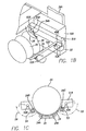
rods edge engaging members wafer boat 24, as indicated byarrows wafer boat 24 can be placed directly on V-shaped intersections formed by boat edge-support arms edge engaging member 53 and V-shaped intersections formed by boatedge support arms support arms 53D are stabilized bymember 53B, and the outer edges of boat edge support aims 54D are stabilized bymember 54B. - The V-shaped intersections formed by boat edge-support anns 53C,53D and boat edge-
support arms wafer boats 24 are accurately aligned with horizontallymoveable arms -
Microcontroller 29 then causesmotor assembly 64 of Fig. 1D to operatebelts 61A and 61B to raise thehorizontal translation devices wafcr boats 24 supported thereby to a level slightly above that of a "destination"cantilever paddle 47, with the wafer boat edge-support arms remaining in the boat-supporting configuration indicated by the solid lines in Figs. 1B and 1C. - Next,
microcontroller 29 operates to move horizontallymoveable arms Microcontroller 29 also adjusts for any needed offset correction as previously described to ensure that the wafer boats are precisely aligned with the longitudinal axis of cantilever paddle 47-1. Control software of thesystem 29 causeshorizontal translation mechanisms cantilever paddle 47, and then gently lower them ontocantilever paddle 47 without any abrasion. This is important because it prevents generation of microscopic particulates which, if present, cause imperfections on the integrated circuits being formed and thereby reduce processing yields.Microcontroller 29 then operatesmotor assembly 64 of Fig. 1D to gently rest thewafer boats 26 onto cantilever paddle 47-1. -
Microcontroller 29 then rotatesrods support arms wafer boats 24, as indicated byarrows Microcontroller 29 then operateselevators horizontal translation mechanisms moveable arms edge support mechanisms rods clear wafers 26.Microcontroller 29 then operates thehorizontal translation mechanisms moveable arms clovators horizontal translation mechanisms cantilever paddle 47. - After all of the
wafers 26 have been loaded onto cantilcvcr paddles 47, moved into corresponding furnace tubes, processed, and withdrawn by thevarious carriages 43, the wafer boat loading/unloading mechanism then is operated in the reverse order from that described above to remove each group of loaded wafer boats from thecantilever paddle 47 and return each group to the location shown in Fig. 1A. All of the wafer boats of each group then can be carried away by an operator, or, if available, an automated shuttle machine. - Referring to Fig. 3, an intermediate
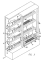
silicon carbide carrier 26A is used instead of using above described waferboat engaging mechanisms silicon carbide carrier 26A is provided with ahook end 26A that is supported by a receivingclement 30 attached to the horizontally moveable arm (not shown) ofhorizontal translation mechanism 50A. A similar hook at the opposite end ofintermediate carrier 26A is supported by a horizontally moveable arm ofhorizontal translation mechanism 50B. Typically, up to eight loaded standard wafer boats (or a long boat carrying 150 or 300 semiconductor wafers then are precisely aligned with and placed onintermediate carrier 26A. If a single long boat is used, its opposite ends can be provided with hook ends that are supported by receivingelements 30, in which case theintermediate carrier 26A is not used. - The vertical translation mechanisms in
elevators horizontal translation mechanisms intermediate carrier 26A and the loaded wafer boats therein ontocantilever paddle 47. After thehorizontal translation mechanisms 50A-50B have been withdrawn from the vicinity ofcantilever paddle 47, thecarriage 42 moves to positioncantilever paddle 47 withintermediate carrier 26 and the up to eight loaded wafer boats in the processing zone of an adjacent furnace tube. - An important advantage of the above described wafer loading system is that a queue mechanism of the type designated by numeral 30 in Fig. 1 of prior art patent 5,765,982 to load or unload individual wafer boats onto or off of a particular cantilever paddle is not used in the present invention. Instead, up to eight wafer boats are simultaneously loaded onto a cantilever paddle or are simultaneously unloaded from the cantilever paddle in the same amount of time required for loading or unloading a single wafer boat in the prior art wafer loading systems. The amount of time required for loading and unloading wafers into the diffusion furnace therefore is reduced by a factor of up to eight or more over the system shown in previously described patent 5,76,982.
- Referring next to Figs. 4A-4D. a horizontal wafer boat transport/
handler system 100 includes a horizontal translation assembly 101 (see Fig. 4C) and aboat support assembly 102 carried by themoveable arms horizontal transport mechanisms -
Boat support assembly 102 is operable to carry a number ofwafer boats 24 loaded withwafers 26 from awafer boat nest 99 on aload platform 87 ofhorizontal translation assembly 101 along a horizontal path to a location (shown in Fig. 4C) immediately overcantilever paddle 47, and to allow the loadedwafer boats 24 to be gently lowered and deposited ontocantilever paddle 47, -
Boat support assembly 102 also is operable under control ofmicrocontroller 29 of Fig. 1G to move clear of (i.e., avoid touching) thewafers 26 in all of thewafer boats 24 resting oncantilever paddle 47 asboat support assembly 102 is moved away fromcantilever paddle 47 after thewafer boats 24 have been loaded oncantilever paddle 47. Afterboat support assembly 102 has been withdrawn from the vicinity ofcantilever paddle 47, thewafer boats 24 thereon are moved by thecarriage 16 supportingcantilever paddle 47 into a horizontal furnace tube (not shown) for wafer processing. - After the wafer processing is complete,
cantilever paddle 47,wafer boats 24 and the processed wafers are withdrawn from the furnace tube.Boat support assembly 102 then is moved back overcantilever paddle 47 and then is operable to pick up all of thewafer boats 24 fromcantilever paddle 47 and carry them and the processedwafers 26 back to a location immediately aboveload platform 87.Load platform 87 then is raised so as to support thewafer boats 24. - The above mentioned
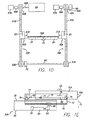
wafer boat nest 99 includes a wafer boat locating nest 93, a plurality of precisely positioned raised features 90, and a plurality ofposition adjustment slots 94. Screws (not shown) extending throughposition adjustment slots 94 into thesupper surface 87A ofload platform 87 to attachwafer boat nest 99 thereto.Load platform 87 rests on athick support plate 103 that extends fromplate 59B of mountingbracket 59 toplate 88B of mountingbracket 88, - The drawing in Fig. 4B is essentially identical to the drawing in Fig. 4A, except that in Fig. 4B the
upper surface 87A is lower than in Fig. 4A because theiniemal bladder 107 shown in subsequently described Fig. 5 has been deflated so as tolower surface 87A. - The
upper surface 87A ofload platform 87 can be precisely raised and lowered by means of an elongated, inflatable bladder and inflation pump as shown in Fig. 5 to allowwafer boat nest 99 to be lowered enough to clear the lowest portions ofboat support assembly 102 andwafer boats 24 aswafer boats 24 are carried betweenload platform 87 and the location shown in Fig-4C. - Referring to Fig. 5,
load platform 87 includes a moveable outer invertedU-shaped section 87B which is "nested" over a stationary innerlower section 87C that is rigidly attached to supportplate 103. Note that in Figs. 4A-C the upper surface of U-shapedupper section 87B is designated byreference numeral 87A. Thebladder 107 includes a hollowinflatable section 107A that can rest on a suitable platform supported bysupport plate 103. Hollowinflatable section 107A preferably directly supports the horizontal upper inner surface ofouter section 87B, butbladder 107 can include an optional uppersolid section 107B that supports the horizontal upper inner surface ofouter section 87B. In any case,bladder 107 is inflated or deflated by a compressed air source controlled bymicrocontroller 29 of Fig. 1G to raise and lowerwafer boat nest 99. - The control of raising and lowering
outer section 87B andwafer boat nest 99 andwafer boats 24 thereon is very precise, and the structure shown in Fig. 4 is quite inexpensive. - Next, the structure of
boat support assembly 102 will be described in detail. Figs. 4B and 4C showwafer boats 24 supported by astationary support rail 97 and amoveable support rail 96. Fig. 4C showsboat support assembly 102 precisely positioned and aligned directly abovecantilever paddle 47.Stationary support rail 97 andmoveable support rail 96 each include one or a plurality ofrigid support tabs 95. which can be composed of suitable high temperature material such as ceramic, silicon carbide or polyamide. Some of thesupport tabs 95 are attached to the vertical inner face ofstationary support rail 97, and the rest ofsupport tabs 95 are attached to the inner vertical face ofmoveable support rail 96, as shown in Figs, 4A-4C.Support tabs 95 directly engage the lower surfaces of the opposed support edges along either side ofwafer boat 24 as to support it andwafers 26. -
Stationary support rail 97 is attached by a pair of plates such as 92 in Figs. 4A-4D to the inner face of a first supportdrive mounting platc 89A that is attached to horizontallymoveable arm 51A ofhorizontal translation mechanism 50A and to the inner face of a second supportdrive mounting plate 89B supported by horizontallymoveable arm 51B ofhorizontal translation assembly 50B. -
Moveable support rail 96 is rigidly attached to the outer ends of a pair ofrotary support arms rotary support arms drive mount plates DC servo motors microcontroller 29 of Fig. 1G. - In operation,
wafer boats 24 loaded withwafers 26 initially are placed onwafer boat nest 99. The raised features 90 ofwafer boat nest 99 ensure precise placements of thewafer boats 24 onload platform 87, and hence later oncantilever paddle 47, and still later within the furnace tubc. Next,internal bladder 107 is precisely deflated under control ofmicroprocessor 29, lowering theupper surface 87A ofload platform 87 to the level shown in Fig. 4B so the opposed parallel support edges of thewafer boats 24 are supported by thefinger tabs 95 onstationary rail 97 andmoveable rail 96. - The
vertical drives microcontroller 29 to position thewafer boats 24 at a suitable vertical level relative to theparticular cantilever paddle 47 onto which thewafer boats 24 are to be loaded. - Next,
horizontal translation mechanisms horizontal translation arms upper surface 87A ofload platform 87 has been lowered enough to clear the wafer boats and the lowest portions of theboat support assembly 102 as it is moved from the position shown in Fig. 4B to the position shown in Fig. 4C.Wafcr boats 24 then arc gently lowered ontocantilever paddle 47, wherein the vertical translation mechanisms shown in Fig. 1D are actuated to lowerhorizontal translation assemblies wafer boats 24 rest oncantilever paddle 47. Precise alignment ofboat support assembly 102 andwafer boats 24 withcantilever paddle 47 is achieved by operating themicrocontroller 29 to monitor the twohorizontal rotary encoders 85 ofhorizontal translation mechanisms sensors - The vertical drives of Fig. 1D then arc operated to lower
moveable support rail 96 andstationary support rail 97 enough to disengage it from the lower support edge surfaces of thewafer boats 24. As shown in Fig. 4D,rotary arms moveable support rail 96 then are rotated byDC servo motors moveable support rail 96 overwafers 26 inwafer boat 24, as shown. Thehorizontal translation mechanisms boat support assembly 102 away from thewafer boats 24 incantilever paddle 47.Movable support rail 96 is lowered, andboat support assembly 100 to is returned to the home position. - Next,
cantilever paddle 47 andwafer boats 24 thereon arc moved horizontally bycarriage 16 into the furnace tube, wherein thewafers 26 are processed. After the wafer processing is complete,cantilever paddle 47 andwafer boats 24 are withdrawn from the furnace tube. The horizontal wafer boat transport/handler system 100 then is operated under control ofmicrocontroller 29 in the reverse order from that described above so as to engage the support edge surfaces ofwafer boats 24 and lift them fromcantilever paddle 47, return them to a position precisely overload platform 87 andwafer boat nest 99.Bladder 107 then is inflated under control ofmicrocontroller 29 to raiseload platform 87 enough to causewafer boat nest 99 to support thewafer boats 24, so as to allowwafer boats 24 to be removed fromload platform 87, either by a human operator or a robotic machine. - While the invention has been described with reference to several particular embodiments thereof, those skilled in the art will be able to make the various modifications to the described embodiments of the invention without departing from the true spirit and scope of the invention. It is intended that all elements or steps which are insubstantially different or perform substantially the same function in substantially the same way to achieve the same result as what is claimed arc within the scope of the invention. For example, the belts and pulleys disclosed could be replaced by corresponding chains and sprockets. A different mechanism could be used for raising and lowering
moveable rail 96.
Claims (13)
- An apparatus for automatically and simultaneously loading a plurality of wafer boats onto a cantilever paddle, and for automatically and simultaneously unloading the loaded wafer boats from the cantilever paddle, comprising:(a) a stationary track aligned with a first opening of a furnace, and a first carriage moveable on the, the first carriage supporting the cantilever paddle;(b) a first vertical translation mechanism including a first stationary part and a first vcrtically moveable support, and a second vertical translation mechanism including a second stationary part and a second vertically moveable support:(c) a first horizontal translation mechanism having a first base supported by the first vertically moveable support and a first horizontally moveable arm supported by the first base, and a second horizontal translation mechanism having a second base supported by the second vertically moveable support and a second horizontally moveable arm supported by the second base;(d) a horizontal support apparatus adapted to support a plurality of wafer boats each loaded with semiconductor wafers, the horizontal support apparatus having a first end supported by the first horizontally moveable arm and a second end supported by the second horizontally moveable arm; and(e) a stationary wafer boat cdgc support member having a first end supported in fixed relationship to the first horizontally moveable arm and a second end supported in fixed relationship to the second horizontally moveable arm. and a moveable wafer boat edge support member having a first end supported in moveable relationship to the first horizontally moveable arm and a second end supported in moveabic relationship to the second horizontally moveable arm, the moveable wafer boat edge support member including first and second end portions supported by outer ends of first and second rotary arms, respectively, having inner end portions supported by first and second rotary drive mechanisms attached in fixed relationship to the first and second horizontally moveable arms, respectively.
- The apparatus of Claim 1 wherein the first and second roiary drive mechanisms rotate the first and second rotary arms, respectively, to bring the moveable wafer boat edge support member into a lower first position to engage an edge of each of the wafer boats and to an upper second position above the wafers in the wafer boats to clear the wafers as the first and second horizontal translation mechanisms are withdrawn from the wafer boats after they are set on the cantilever paddle.
- The apparatus of Claim 2 wherein the first and second rotary drive mechanisms include first and second DC servo motors, respectively.
- The apparatus of Claim 3 wherein the stationary wafer boat edge support member includes a first stainless steel rail, and the moveable wafer boat edge support member includes a second stainless steel rail, the apparatus further including a plurality of support fingers rigidly attached to the first and second rails, respectively, for engaging wafer boat edge support surfaces of the wafer boats.
- The apparatus of Claim 4 wherein the support fingers arc composed of high ternperature material.
- The apparatus of Claim 2 including a load platform mechanism attached in fixed relationship to the first and second vertical translation mechanisms for receiving and supporting the wafer boats.
- The apparatus of Claim 6 wherein the load platform mechanism includes an upper surface plate that is movcable relative to a lower portion of the load platform mechanism so as to clear the horizontal support apparatus and wafer boats supported thereby as the wafer boats are carried between the cantilever paddle and the load platform mechanism.
- The apparatus of Claim 7 wherein the load platform mechanism includes an internal inflatable bladder disposed between the upper surface plate and the lower portion of the load platform mechanism and adapted to precisely control the elevation of the upper surface plale relative to the lower portion of the load platform mechanism.
- A method of automatically loading at least one wafer boat onto a cantilever paddle. comprising:(a) providing first and second vertical translation devices having first and second vertically movcable supports, respectively, and also providing a first horizontal translation device having both a first base attached to the first moveable support and a first horizontally moveable arm, and a second horizontal translation device having both a second base attached to the second moveable support and a second horizontally moveable arm:(b) supporting a first end of a horizontal support apparatus adapted to support a plurality of wafer boats each loaded with semiconductor wafers by means of the first horizontally moveable arm, and supporting a second end of the horizontal support apparatus by means of the. second horizontally moveable arm;(c) positioning a stationary wafer boat edge support member so it can engage a first edge of the wafer boat, and positioning a moveable boat edge support member so it can engage a second edge of the wafer boat;(d) lowering a platform supporting the wafer boat so the first and second edges of the wafer boat rest on the stationary wafer boat edge support member and the moveable wafer boat cdgc support member, respectively, so the wafer boat can clear the platform during step (e);(e) operating the first and second horizontal translation devices to move the first and second horizontally moveable arms to first and second positions, respectively, proximate to the cantilever paddle;(f) lowering the wafer boat onto the cantilever paddle; and(g) raising the moveable wafer boat edge support member higher than the tops of the wafers, and horizontally retracting the horizontal support apparatus so the stationary and moveable wafer boat edge support members clear the first and second edges of the wafer boat.
- The method of Claim 9 including horizontally moving the cantilever paddle and wafer boat and wafers thereon into a furnace for wafer processing, returning the cantilever paddle, wafer boat and wafers from the furnace when wafer processing is complete, then operating the first and second horizontal translation devices so as to move the horizontal support apparatus, with the moveable wafer boat edge support member in its raised position so the stationary wafer boat edge support member is positioned to engage the second edge of the wafer boat, lowering the moveable wafer boat edge support member so it is positioned to engage the second edge of the wafer boat, operating the first and second vertical translation devices to lift the wafer boat from the cantilever paddle by the first and second edges of the wafer boat, and operating the first and second horizontal translation devices to carry the wafer boat and processed wafers over the platform.
- The method of Claim 10 including raising the platform so as to lift the wafer boat so as to raise the first edge of the wafer boat above the stationary wafer boat support member and to raise the second wafer boat edge above the moveable wafer boat edge support member, and raising the moveable wafer boat edge support member to its raised position so as to allow the wafer boat and processed wafers thereon to be removed from the platform.
- The method of Claim 11 wherein the lowering and raising of the platform is performed by deflating and inflating, respectively, a bladder mechanism supporting the platform.
- An apparatus for automatically and simultaneously loading a plurality of wafer boats onto a cantilever paddle, and for automatically and simultaneously unloading the loaded wafer boats from the cantilever paddle, comprising:(a) a track aligned with a first opening of a furnace, and a first carriage moveable on the, the first carriage supporting the cantilever paddle;(b) a first vertical translation mechanism including a first stationary part and a first vertically moveable support, and a second vertical translation mechanism including a second stationary part and a second vertically moveable support;(c) a first horizontal translation mechanism having a first base supported by the first vertically moveable support and a first horizontally moveable arm supported by the first base, and a second horizontal translation mechanism having, a second base supported by the second vertically moveable support and a second horizontally moveable arm supported by the second base;(d) a horizontal support apparatus adapted to support a plurality of wafer boats each loaded with semiconductor wafers, the horizontal support apparatus having a first end supported by the first horizontally moveable arm and a second end supported by the second horizontally moveable arm;(e) a first wafer boat edge support member having a first end supported by the first horizontally moveable arm and a second end supported by the second horizontally moveable arm, and a second wafer boat edge support member having a first end supported by the first horizontally moveable arm and a second end supported by the second horizontally moveable arm; and(1) a load platform mechanism for receiving and supporting the wafer boats, the load platform mechanism including an upper surface that is moveable relative to a lower portion of the load platform mechanism so as to clear the horizontal support apparatus and wafer boats supported thereby as the wafer boats are carried between the cantilever paddle and the load platform mechanism, the load platform mechanism including an internal inflatable bladder disposed between the upper surface and the lower portion of the load platform mechanism and adapted to precisely control the elevation of the upper surface plate relative to the lower portion of the load platform mechanism in response to inflation/deflation of the bladder.
Applications Claiming Priority (2)
| Application Number | Priority Date | Filing Date | Title |
|---|---|---|---|
| US19251600P | 2000-03-28 | 2000-03-28 | |
| US192516 | 2000-03-28 |
Publications (3)
| Publication Number | Publication Date |
|---|---|
| EP1139392A2 true EP1139392A2 (en) | 2001-10-04 |
| EP1139392A3 EP1139392A3 (en) | 2006-01-25 |
| EP1139392B1 EP1139392B1 (en) | 2007-08-15 |
Family
ID=22709990
Family Applications (1)
| Application Number | Title | Priority Date | Filing Date |
|---|---|---|---|
| EP20010107075 Expired - Lifetime EP1139392B1 (en) | 2000-03-28 | 2001-03-21 | Improved wafer boat support and method for twin tower wafer boat loader |
Country Status (2)
| Country | Link |
|---|---|
| EP (1) | EP1139392B1 (en) |
| DE (1) | DE60129870D1 (en) |
Cited By (1)
| Publication number | Priority date | Publication date | Assignee | Title |
|---|---|---|---|---|
| CN112117349A (en) * | 2020-09-09 | 2020-12-22 | 湖州奥博石英科技有限公司 | Solar cell silicon wafer diffusion insert process |
Citations (4)
| Publication number | Priority date | Publication date | Assignee | Title |
|---|---|---|---|---|
| EP0158900A2 (en) * | 1984-04-19 | 1985-10-23 | Heraeus Quarzglas GmbH | Installation for feeding an oven system automatically with semi-conductor chips |
| JPS62128523A (en) * | 1985-11-29 | 1987-06-10 | Mitsubishi Electric Corp | Carry-in-out device to heat treating furnace of wafer housing boat |
| US5069591A (en) * | 1988-03-24 | 1991-12-03 | Tel Sagami Limited | Semiconductor wafer-processing apparatus |
| US5765982A (en) * | 1995-07-10 | 1998-06-16 | Amtech Systems, Inc. | Automatic wafer boat loading system and method |
-
2001
- 2001-03-21 EP EP20010107075 patent/EP1139392B1/en not_active Expired - Lifetime
- 2001-03-21 DE DE60129870T patent/DE60129870D1/en not_active Expired - Lifetime
Patent Citations (5)
| Publication number | Priority date | Publication date | Assignee | Title |
|---|---|---|---|---|
| EP0158900A2 (en) * | 1984-04-19 | 1985-10-23 | Heraeus Quarzglas GmbH | Installation for feeding an oven system automatically with semi-conductor chips |
| JPS62128523A (en) * | 1985-11-29 | 1987-06-10 | Mitsubishi Electric Corp | Carry-in-out device to heat treating furnace of wafer housing boat |
| US5069591A (en) * | 1988-03-24 | 1991-12-03 | Tel Sagami Limited | Semiconductor wafer-processing apparatus |
| US5765982A (en) * | 1995-07-10 | 1998-06-16 | Amtech Systems, Inc. | Automatic wafer boat loading system and method |
| US5888048A (en) * | 1995-07-10 | 1999-03-30 | Amtech Systems, Inc. | Automatic wafer boat loading |
Non-Patent Citations (1)
| Title |
|---|
| PATENT ABSTRACTS OF JAPAN vol. 011, no. 351 (E-557), 17 November 1987 (1987-11-17) & JP 62 128523 A (MITSUBISHI ELECTRIC CORP), 10 June 1987 (1987-06-10) * |
Cited By (1)
| Publication number | Priority date | Publication date | Assignee | Title |
|---|---|---|---|---|
| CN112117349A (en) * | 2020-09-09 | 2020-12-22 | 湖州奥博石英科技有限公司 | Solar cell silicon wafer diffusion insert process |
Also Published As
| Publication number | Publication date |
|---|---|
| EP1139392B1 (en) | 2007-08-15 |
| EP1139392A3 (en) | 2006-01-25 |
| DE60129870D1 (en) | 2007-09-27 |
Similar Documents
| Publication | Publication Date | Title |
|---|---|---|
| US6537010B2 (en) | Wafer boat support and method for twin tower wafer boat loader | |
| US6279724B1 (en) | Automated semiconductor processing system | |
| JP6850725B2 (en) | Board transfer robot and board processing system | |
| US6273110B1 (en) | Automated semiconductor processing system | |
| JPH02297925A (en) | Method and apparatus for transfer of wafer in vertical cvd diffusing device and controller | |
| US6052913A (en) | Positioning device and positioning method | |
| EP1129472A2 (en) | Processing chamber with rapid wafer exchange | |
| KR102091915B1 (en) | Substrate transfer robot and substrate processing system | |
| WO1995030238A1 (en) | Semiconductor wafer processing system | |
| US6942738B1 (en) | Automated semiconductor processing system | |
| US20020150449A1 (en) | Automated semiconductor processing system | |
| JPWO2007029401A1 (en) | Work loading / unloading system and transfer device | |
| JPH01502866A (en) | Automatic wafer loading method and device | |
| JP2004524673A (en) | Automatic processing system | |
| JPH0230194B2 (en) | HANDOTAISEIZOSOCHI | |
| US6352399B1 (en) | Twin tower wafer boat loading system and method | |
| JP3008758B2 (en) | Tire transfer device | |
| US4664575A (en) | Workpiece transferring apparatus for a robot | |
| EP1139392B1 (en) | Improved wafer boat support and method for twin tower wafer boat loader | |
| JP2000512218A (en) | Z-axis drive arm tiltable in all directions | |
| JPH07106402A (en) | Platelike material transfer system | |
| JPH08333008A (en) | Automatic elevating mechanism and automatic high-rise warehouse therewith | |
| JPH06211320A (en) | Wafer carrying-in and out device | |
| JP2002134587A (en) | Mechanism for conveying object to be processed and processing system | |
| JP3762974B2 (en) | Conveying device and warehouse device |
Legal Events
| Date | Code | Title | Description |
|---|---|---|---|
| PUAI | Public reference made under article 153(3) epc to a published international application that has entered the european phase |
Free format text: ORIGINAL CODE: 0009012 |
|
| 17P | Request for examination filed |
Effective date: 20010321 |
|
| AK | Designated contracting states |
Kind code of ref document: A2 Designated state(s): AT BE CH CY DE DK ES FI FR GB GR IE IT LI LU MC NL PT SE TR |
|
| AX | Request for extension of the european patent |
Free format text: AL;LT;LV;MK;RO;SI |
|
| PUAL | Search report despatched |
Free format text: ORIGINAL CODE: 0009013 |
|
| AK | Designated contracting states |
Kind code of ref document: A3 Designated state(s): AT BE CH CY DE DK ES FI FR GB GR IE IT LI LU MC NL PT SE TR |
|
| AX | Request for extension of the european patent |
Extension state: AL LT LV MK RO SI |
|
| RIC1 | Information provided on ipc code assigned before grant |
Ipc: H01L 21/68 20060101AFI20051202BHEP |
|
| AKX | Designation fees paid |
Designated state(s): DE FR GB IT NL |
|
| GRAP | Despatch of communication of intention to grant a patent |
Free format text: ORIGINAL CODE: EPIDOSNIGR1 |
|
| GRAS | Grant fee paid |
Free format text: ORIGINAL CODE: EPIDOSNIGR3 |
|
| GRAA | (expected) grant |
Free format text: ORIGINAL CODE: 0009210 |
|
| AK | Designated contracting states |
Kind code of ref document: B1 Designated state(s): DE FR GB IT NL |
|
| REG | Reference to a national code |
Ref country code: GB Ref legal event code: FG4D |
|
| REF | Corresponds to: |
Ref document number: 60129870 Country of ref document: DE Date of ref document: 20070927 Kind code of ref document: P |
|
| ET | Fr: translation filed | ||
| PG25 | Lapsed in a contracting state [announced via postgrant information from national office to epo] |
Ref country code: NL Free format text: LAPSE BECAUSE OF FAILURE TO SUBMIT A TRANSLATION OF THE DESCRIPTION OR TO PAY THE FEE WITHIN THE PRESCRIBED TIME-LIMIT Effective date: 20070815 |
|
| NLV1 | Nl: lapsed or annulled due to failure to fulfill the requirements of art. 29p and 29m of the patents act | ||
| PLBE | No opposition filed within time limit |
Free format text: ORIGINAL CODE: 0009261 |
|
| STAA | Information on the status of an ep patent application or granted ep patent |
Free format text: STATUS: NO OPPOSITION FILED WITHIN TIME LIMIT |
|
| 26N | No opposition filed |
Effective date: 20080516 |
|
| PG25 | Lapsed in a contracting state [announced via postgrant information from national office to epo] |
Ref country code: DE Free format text: LAPSE BECAUSE OF FAILURE TO SUBMIT A TRANSLATION OF THE DESCRIPTION OR TO PAY THE FEE WITHIN THE PRESCRIBED TIME-LIMIT Effective date: 20071116 |
|
| PGFP | Annual fee paid to national office [announced via postgrant information from national office to epo] |
Ref country code: GB Payment date: 20080530 Year of fee payment: 8 |
|
| GBPC | Gb: european patent ceased through non-payment of renewal fee |
Effective date: 20090321 |
|
| PG25 | Lapsed in a contracting state [announced via postgrant information from national office to epo] |
Ref country code: GB Free format text: LAPSE BECAUSE OF NON-PAYMENT OF DUE FEES Effective date: 20090321 |
|
| PG25 | Lapsed in a contracting state [announced via postgrant information from national office to epo] |
Ref country code: IT Free format text: LAPSE BECAUSE OF NON-PAYMENT OF DUE FEES Effective date: 20080331 |
|
| REG | Reference to a national code |
Ref country code: FR Ref legal event code: PLFP Year of fee payment: 16 |
|
| PGFP | Annual fee paid to national office [announced via postgrant information from national office to epo] |
Ref country code: FR Payment date: 20160328 Year of fee payment: 16 |
|
| REG | Reference to a national code |
Ref country code: FR Ref legal event code: ST Effective date: 20171130 |
|
| PG25 | Lapsed in a contracting state [announced via postgrant information from national office to epo] |
Ref country code: FR Free format text: LAPSE BECAUSE OF NON-PAYMENT OF DUE FEES Effective date: 20170331 |