EP1136662A2 - Position measuring device of electromagnetically operated engine valve drive system and method for attaching the same - Google Patents
Position measuring device of electromagnetically operated engine valve drive system and method for attaching the same Download PDFInfo
- Publication number
- EP1136662A2 EP1136662A2 EP20010107085 EP01107085A EP1136662A2 EP 1136662 A2 EP1136662 A2 EP 1136662A2 EP 20010107085 EP20010107085 EP 20010107085 EP 01107085 A EP01107085 A EP 01107085A EP 1136662 A2 EP1136662 A2 EP 1136662A2
- Authority
- EP
- European Patent Office
- Prior art keywords
- engine
- electromagnetic
- actuator
- valve
- drive system
- Prior art date
- Legal status (The legal status is an assumption and is not a legal conclusion. Google has not performed a legal analysis and makes no representation as to the accuracy of the status listed.)
- Granted
Links
Images


Classifications
-
- F—MECHANICAL ENGINEERING; LIGHTING; HEATING; WEAPONS; BLASTING
- F01—MACHINES OR ENGINES IN GENERAL; ENGINE PLANTS IN GENERAL; STEAM ENGINES
- F01L—CYCLICALLY OPERATING VALVES FOR MACHINES OR ENGINES
- F01L1/00—Valve-gear or valve arrangements, e.g. lift-valve gear
- F01L1/46—Component parts, details, or accessories, not provided for in preceding subgroups
-
- F—MECHANICAL ENGINEERING; LIGHTING; HEATING; WEAPONS; BLASTING
- F01—MACHINES OR ENGINES IN GENERAL; ENGINE PLANTS IN GENERAL; STEAM ENGINES
- F01L—CYCLICALLY OPERATING VALVES FOR MACHINES OR ENGINES
- F01L9/00—Valve-gear or valve arrangements actuated non-mechanically
- F01L9/20—Valve-gear or valve arrangements actuated non-mechanically by electric means
-
- Y—GENERAL TAGGING OF NEW TECHNOLOGICAL DEVELOPMENTS; GENERAL TAGGING OF CROSS-SECTIONAL TECHNOLOGIES SPANNING OVER SEVERAL SECTIONS OF THE IPC; TECHNICAL SUBJECTS COVERED BY FORMER USPC CROSS-REFERENCE ART COLLECTIONS [XRACs] AND DIGESTS
- Y10—TECHNICAL SUBJECTS COVERED BY FORMER USPC
- Y10T—TECHNICAL SUBJECTS COVERED BY FORMER US CLASSIFICATION
- Y10T137/00—Fluid handling
- Y10T137/8158—With indicator, register, recorder, alarm or inspection means
- Y10T137/8225—Position or extent of motion indicator
- Y10T137/8242—Electrical
Definitions
- the present invention relates to a position measuring device of an electromagnetic actuator for an electromagnetically operated engine valve drive system and a method for attaching the same.
- a cam shaft drive system has still been dominated in an open-and-closure drive of intake and exhaust valves of an electronically controlled internal combustion engine although the electronically controlled engine has been adopted in automotive vehicles.
- valve open-and -closure timing and valve displacement controls can optimally be made under various engine driving situations. To achieve this, it is necessary to detect accurately a position of a movable section of the electromagnetic actuator which reciprocates at a high velocity so that the valve displacement of the intake or exhaust valve can be recognized.
- a position measuring device utilizing a Hall effect has been used in the above-described electromagnetically operated engine valve drive system.
- a kind of the position measuring device includes a magnetic field generating and detecting device (coupler) of a permanent magnet and a Hall effect device.
- a Japanese Patent Application First Publication No. Heisei 6-180242 published on June 28, 1994 exemplifies an area airflow meter to which the above-described position detecting device of the permanent magnet and Hall effect devices (or magnetic resistance elements) is applied.
- one of the permanent magnet and the magnetic field detecting device for example, the permanent magnet is attached onto its movable section, a strength of the magnetic field that the permanent magnet creates is measured by the attached magnetic field detecting device so that the position of the movable section can be measured.
- the movable section of the actuator Since, in the previously proposed electromagnetically operated engine valve drive system, the movable section of the actuator has a considerably high velocity in the vicinities of start and end points of the stroke by which the movable section can be moved. Hence, if the movable section collide with a stationary section of the actuator at a high velocity region at proximities to the start and end points of the stroke, a large impulsive (collision) force due to an acceleration reaching up to several thousand's G (gravity) would be received.
- G gravitation
- a velocity variation control during the stroke has been applied such that the position of the movable section is measured and the velocity of the movable section is slowed down at proximities of start and end points of the stroke.
- the movable section of the actuator is made of a ferromagnetic material such as a steel integrated with a movable element such as an armature for electromagnets.
- an object of the present invention to provide improved position measuring device for the electromagnetically operated engine valve drive system and method for attaching the same which can sufficiently suppress a reduction of a reliability in the attaching of the position detecting device onto the movable section of the electromagnetically operated engine valve drive system and can sufficiently suppress a reduction of a position measuring accuracy due to the attaching of the permanent magnet onto the movable section of the actuator with a simple structure.
- a method for attaching a position measuring device of an electromagnetic actuator for an electromagnetically operated engine valve drive system comprising: a movable section associated with an engine valve; and a permanent magnet used to detect a displacement position of the movable section, the method comprising attaching the permanent magnet onto the movable section via such a predetermined material as to have a lower hardness than that of the movable section.
- a position measuring device of an electromagnetic actuator for an electromagnetically operated engine valve drive system comprising: a movable section associated with an engine valve; and a permanent magnet attached onto the movable section via such a predetermined material as to have a lower hardness than that of the movable section to detect a displacement position of the movable section.
- Fig. 1 is a schematic cross sectional view of an electromagnetic actuator for an electromagnetically operated engine valve drive system to which a first preferred embodiment of an attaching method for a permanent magnet onto a movable section of the electromagnetic actuator for the electromagnetically operated engine valve drive system according to the present invention is applicable.
- Fig. 2 is an expanded view of an essential part of the movable section of the electromagnetic actuator in the first preferred embodiment shown in Fig. 1.
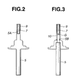
- Fig. 3 is an expanded view of an essential part of the movable section to which a second preferred embodiment of the attaching method of the permanent magnet according to the present invention is applicable.
- Fig. 4 is a characteristic graph representing a relationship between a gap length and a measurement error in the second preferred embodiment shown in Fig. 3.
- Fig. 1 shows an example of an electromagnetic actuator for an electromagnetically operated engine valve drive system to which a method for attaching a permanent magnet onto a movable section of the electromagnetic actuator in a first preferred embodiment according to the present invention is applicable.
- An electromagnetic actuator 100 includes: a main body, viz., a stationary section; and a movable section.
- the main body includes: an upper casing C1; and a lower casing C2 within which a pair of first and second electromagnets 2 and 3 are housed.
- the movable section includes a drive axle 5 having an armature 1 (also called, a movable element) made of a material having a magnetic property.
- a spring 4 is interposed between the movable section and the upper casing C1 of the stationary section.
- An engine valve 6 an intake valve or exhaust valve
- first electromagnet 2 is energized to attract armature 1 thereonto so that armature 1, viz., engine valve 6 is held at a closure position denoted by a phantom line of 1 x and, therefore, engine valve 6 has reached onto a valve seat 20.
- second electromagnet 3 is energized (first electromagnet 2 is de-energized) to attract armature 1 thereonto so that armature 1, viz., engine valve 6 is held at an open position denoted by a solid line of 1 and, therefore, engine valve 6 has separated in the downward direction (combustuion chamber side) from valve seat 20.
- spring 4 serves to bias armature 1 at a neutral position (denoted by a phantom line of 1 Y ) which corresponds to an intermediate position of engine valve 6 between closure position and open position during no power supply to first and second electromagnets 2 and 3.
- valve seat 20 is attached onto an intake port or exhaust port of an internal combustion engine so that an end of a valve body of engine valve 6 is faced toward combustion chamber side and first and second electromagnets 2 and 3 are electrically connected to a controller via terminals 22 located at a screw head 21 of the main body as shown in Fig. 1.
- both controls of a valve open timing and a valve closure timing are independently made possible and a valve displacement control is also made possible using the controller. To achieve these controls, it is necessary to control accurately a driven position of armature 1. At this time, it is necessary to measure accurately the position of the engine valve 6.
- a bar shaped permanent magnet 7 and a Hall effect device 8 are mounted on the main body, viz., the stationary section and the movable section of electromagnetic actuator 100 to form a position measuring device (coupler).
- Permanent magnet 7 is attached, as shown in Fig. 1, onto an upper end of drive axle 5 which is opposite to a lower end of drive axle 5 onto which engine valve body 6 is attached.
- the solid-state Hall effect device 8 is attached onto main body, viz., the stationary section of the actuator 100 so as to face against permanent magnet 7.
- the position of permanent magnet 7 with respect to Hall effect device 8 is changed according to a displacement of drive axle 5 so that a strength of a magnetic field detected by Hall effect device 8 is varied, the position of permanent magnet 7 with respect to the position of Hall effect device 8 can be detected in accordance with the change in the strength of the magnetic field, i.e., the position of engine valve 6 such as the intake valve or exhaust valve can be detected.
- the Hall effect device 8 is juxtaposed to a movement direction of armature 1.
- armature 1 When armature 1 is placed at the neutral position, a center position of an elongated direction of permanent magnet 7 whose upper and lower ends are magnetic poles is adjusted to become coincident with that of Hall effect device 8.
- Hall effect device 8 can measure a magnetic field strength generated radially from permanent magnet 7 so that the position of armature 1 can be measured.
- a reference numeral 9 denotes an adhesive layer by means of which permanent magnet 7 is attached onto the upper end of drive axle 5.
- Fig. 2 shows an expanded view of the attaching portion of permanent magnet 7 to drive axle 5 by means of adhesive layer 9.
- a cylindrical portion 5A is formed on the upper end of drive axle 5.
- Permanent magnet 7 can be inserted into the cylindrical portion 5A with a predetermined clearance.
- the epoxy resin series adhesive has a superior characteristic such that a predetermined intensity can be maintained while maintaining an elasticity to some degree due to its composition.
- permanent magnet 7 can elastically be held with a sufficient strength against drive axle 5. Even if a strong shock (impulsive force) is applied to armature 1, permanent magnet 7 can easily be protected and a sufficiently high reliability can be maintained.
- a Samarium-Cobalt series permanent magnet material is often used in permanent magnet 7 for the position detection in the electromagnetically operated engine valve drive system from the standpoints of a thermal stability, an anti-corrosion characteristic, and a high coercive force characteristic.
- this permanent magnet material is considerably fragile.
- the reliability of the system cannot be maintained.
- the impulsive force is absorbed due to the presence of adhesive layer 9 and the impulsive force applied to permanent magnet 7 is sufficiently relieved and, hence, the reliability can sufficiently be maintained.
- adhesive layer 9 such a material as to have a function required for the impulsive force applied from drive axle 5 to be relived on permanent magnet 7, viz., such a material as to have a lower hardness than the material of drive axle 5 is adopted regardless of a property of the material.
- adhesive layer 9 is not only made of the epoxy resin series adhesive but also may be made of another synthetic resin series adhesive. Furthermore, permanent magnet 7 may be held by filing a metal such as Aluminium or Copper within cylindrical portion 5A.
- Fig. 3 shows an expanded view of the upper end of drive axle 5 shown in Fig. 1.
- a reference numeral 10 denotes a hollow cylindrical member (sleeve) made of a non-magnetic property material.
- a small diameter section 5B is formed on the upper end of the drive axle 5 whose diameter is finer than outer cylindrical member 10.
- a lower end of permanent magnet 7 is formed with a spatial gap section (G) against the upper end of small diameter section 5B.
- the permanent magnet 7 is attached onto the drive axle 5 via adhesive layer 9 and is attached onto drive axle 5 via cylindrical member 10 having the low hardness than the drive axle 5. Consequently, even if the strong impulsive force is applied to the armature 1, adhesive layer 9 serves to absorb the impulsive force so that the impulsive force to be applied to permanent magnet 7 is sufficiently relieved. Hence, a sufficient reliability can be maintained.
- permanent magnet 7 is held with cylindrical member 10 made of the non-magnetic property material such as Alminium, there is no possibility that the magnetic field due to the presence of permanent magnet 7 is disturbed by a magnetic property material present in a proximity to permanent magnet 7.
- the gap section G which serves as a magnetic shield member is formed around the lower end of permanent magnet 7, there is no possibility that the magnetic field developed by permanent magnet 7 is disturbed by the presence of drive axle 5 which is the magnetic property material.
- the magnetic field developed by permanent magnet 7 is detected so that the position of the permanent magnet can be detected.
- This error in the symmetry appears in a form of a reduction in the strength of a magnetic field in the proximity to the magnetic poles of permanent magnet 7 near to the magnetic property material. Hence, a reduction in a sensitivity of measuring the position is resulted.
- Fig. 4 shows a result of measurement of a relationship between a length of gap section G and the measurement error.
- the magnetic shield material such as a permalloy (Ni 77 to 85 %, Fe 10 to 20 %, and Cr 2 to 4 % (or Mo 4 %)) may be inserted or filled in gap section G so that the gap length thereof can be shortened.
- the electromagnetically operated engine valve drive system includes the electromagnetic actuator 100 and controller and electromagnetic actuator 100 shown in Fig. 1 is disposed in each of cylinders of the electronically controlled internal combustion engine.
Landscapes
- Engineering & Computer Science (AREA)
- Mechanical Engineering (AREA)
- General Engineering & Computer Science (AREA)
- Valve Device For Special Equipments (AREA)
- Electromagnets (AREA)
- Measurement Of Length, Angles, Or The Like Using Electric Or Magnetic Means (AREA)
- Transmission And Conversion Of Sensor Element Output (AREA)
- Standing Axle, Rod, Or Tube Structures Coupled By Welding, Adhesion, Or Deposition (AREA)
- Vibration Dampers (AREA)
- Magnetically Actuated Valves (AREA)
Abstract
Description
- The present invention relates to a position measuring device of an electromagnetic actuator for an electromagnetically operated engine valve drive system and a method for attaching the same.
- A cam shaft drive system has still been dominated in an open-and-closure drive of intake and exhaust valves of an electronically controlled internal combustion engine although the electronically controlled engine has been adopted in automotive vehicles.
- As the electronically controlled engine has become generalized, an application of an electronic control system to the open-and-closure drive system for the intake and exhaust valves has strongly been demanded from standpoints of a further improvement in a fuel consumption and an exhaust gas purification.
- To meet this demand, a United States Patent No. 5,769,043 issued on June 23, 1998 to James A. Nitkiewicz has proposed an apparatus for electromagnetically driving the intake and exhaust valves to open and close intake and exhaust ports of the engine using an electromagnet actuator, viz., an electromagnetically operated engine valve drive system.
- In the above-described electromagnetically operated engine valve drive system, independent controls of both of a valve open timing and a valve closure timing and, furthermore, a valve displacement control are made possible.
- These valve open-and -closure timing and valve displacement controls can optimally be made under various engine driving situations. To achieve this, it is necessary to detect accurately a position of a movable section of the electromagnetic actuator which reciprocates at a high velocity so that the valve displacement of the intake or exhaust valve can be recognized.
- In this case, it is generally necessary to measure an instantaneous position of the movable section of the actuator with an extremely high accuracy and with no contact over a considerably long stroke. To meet this necessity, a position measuring device utilizing a Hall effect has been used in the above-described electromagnetically operated engine valve drive system. A kind of the position measuring device includes a magnetic field generating and detecting device (coupler) of a permanent magnet and a Hall effect device.
- A Japanese Patent Application First Publication No. Heisei 6-180242 published on June 28, 1994 exemplifies an area airflow meter to which the above-described position detecting device of the permanent magnet and Hall effect devices (or magnetic resistance elements) is applied.
- In the above-identified Japanese Patent Application First Publication, one of the permanent magnet and the magnetic field detecting device, for example, the permanent magnet is attached onto its movable section, a strength of the magnetic field that the permanent magnet creates is measured by the attached magnetic field detecting device so that the position of the movable section can be measured.
- In the above-described previously proposed electromagnetically operated engine valve drive system, no consideration is given to an attaching of the permanent magnet onto the movable section of the valve actuator so that a reduction in a reliability cannot be avoided and a maintenance of a measuring accuracy becomes difficult.
- Since, in the previously proposed electromagnetically operated engine valve drive system, the movable section of the actuator has a considerably high velocity in the vicinities of start and end points of the stroke by which the movable section can be moved. Hence, if the movable section collide with a stationary section of the actuator at a high velocity region at proximities to the start and end points of the stroke, a large impulsive (collision) force due to an acceleration reaching up to several thousand's G (gravity) would be received.
- Therefore, in order to avoid an occurrence of the collision, to suppress the collision velocity to be low even when such a collision as described above has occurred, to reduce a noise or shock, or to achieve a long extension of life, a velocity variation control during the stroke has been applied such that the position of the movable section is measured and the velocity of the movable section is slowed down at proximities of start and end points of the stroke.
- However, even if the velocity variation control has been applied, the occurrence in the collision of the movable section with the stationary section cannot be avoided when an initial adjustment of the device is carried out or when an abnormality in a controller for controlling the electromagnetically operated engine valve drive system occurs although no collision may occur in a steady state.
- Since no consideration for the attaching of the position detecting permanent magnet with respect to the movable section of the valve actuator is given, so that a reliability of the permanent magnet would be reduced.
- At this time, it is a general practice that the movable section of the actuator is made of a ferromagnetic material such as a steel integrated with a movable element such as an armature for electromagnets.
- In the above-described previously proposed position detecting devices, no consideration for the attaching of position detecting permanent magnet onto the movable section of the actuator is given so that a disturbance of the magnetic field due to the permanent magnet occurs and the measurement accuracy can be reduced.
- It is, hence, an object of the present invention to provide improved position measuring device for the electromagnetically operated engine valve drive system and method for attaching the same which can sufficiently suppress a reduction of a reliability in the attaching of the position detecting device onto the movable section of the electromagnetically operated engine valve drive system and can sufficiently suppress a reduction of a position measuring accuracy due to the attaching of the permanent magnet onto the movable section of the actuator with a simple structure.
- According to one aspect of the present invention, there is provided a method for attaching a position measuring device of an electromagnetic actuator for an electromagnetically operated engine valve drive system, the electromagnetic actuator comprising: a movable section associated with an engine valve; and a permanent magnet used to detect a displacement position of the movable section, the method comprising attaching the permanent magnet onto the movable section via such a predetermined material as to have a lower hardness than that of the movable section.
- According to another aspect of the present invention, there is provided a position measuring device of an electromagnetic actuator for an electromagnetically operated engine valve drive system, the position measuring device comprising: a movable section associated with an engine valve; and a permanent magnet attached onto the movable section via such a predetermined material as to have a lower hardness than that of the movable section to detect a displacement position of the movable section.
- This summary of the invention does not necessarily describe all necessary features so that the invention may also be a sub-combination of these described features.
- Fig. 1 is a schematic cross sectional view of an electromagnetic actuator for an electromagnetically operated engine valve drive system to which a first preferred embodiment of an attaching method for a permanent magnet onto a movable section of the electromagnetic actuator for the electromagnetically operated engine valve drive system according to the present invention is applicable.
- Fig. 2 is an expanded view of an essential part of the movable section of the electromagnetic actuator in the first preferred embodiment shown in Fig. 1.
- Fig. 3 is an expanded view of an essential part of the movable section to which a second preferred embodiment of the attaching method of the permanent magnet according to the present invention is applicable.
- Fig. 4 is a characteristic graph representing a relationship between a gap length and a measurement error in the second preferred embodiment shown in Fig. 3.
- Reference will hereinafter be made to the drawings in order to facilitate a better understanding of the present invention.
- Fig. 1 shows an example of an electromagnetic actuator for an electromagnetically operated engine valve drive system to which a method for attaching a permanent magnet onto a movable section of the electromagnetic actuator in a first preferred embodiment according to the present invention is applicable.
- An
electromagnetic actuator 100, as shown in Fig. 1, includes: a main body, viz., a stationary section; and a movable section. The main body (stationary section) includes: an upper casing C1; and a lower casing C2 within which a pair of first andsecond electromagnets drive axle 5 having an armature 1 (also called, a movable element) made of a material having a magnetic property. Aspring 4 is interposed between the movable section and the upper casing C1 of the stationary section. An engine valve 6 (an intake valve or exhaust valve) is attached ontodrive axle 5 associated witharmature 1. - When
engine valve 6 is to be moved in an upward direction of Fig. 1, viz.,engine valve 6 is to be closed,first electromagnet 2 is energized to attractarmature 1 thereonto so thatarmature 1, viz.,engine valve 6 is held at a closure position denoted by a phantom line of 1x and, therefore,engine valve 6 has reached onto avalve seat 20. - When
engine valve 6 is to be moved in a downward direction of Fig. 1, viz.,engine valve 6 is to be opened,second electromagnet 3 is energized (first electromagnet 2 is de-energized) to attractarmature 1 thereonto so thatarmature 1, viz.,engine valve 6 is held at an open position denoted by a solid line of 1 and, therefore,engine valve 6 has separated in the downward direction (combustuion chamber side) fromvalve seat 20. - It is noted that
spring 4 serves to biasarmature 1 at a neutral position (denoted by a phantom line of 1Y) which corresponds to an intermediate position ofengine valve 6 between closure position and open position during no power supply to first andsecond electromagnets - It is also noted that
valve seat 20 is attached onto an intake port or exhaust port of an internal combustion engine so that an end of a valve body ofengine valve 6 is faced toward combustion chamber side and first andsecond electromagnets terminals 22 located at ascrew head 21 of the main body as shown in Fig. 1. - It is further noted that both controls of a valve open timing and a valve closure timing are independently made possible and a valve displacement control is also made possible using the controller. To achieve these controls, it is necessary to control accurately a driven position of
armature 1. At this time, it is necessary to measure accurately the position of theengine valve 6. - Therefore, as shown in Fig. 1, a bar shaped
permanent magnet 7 and aHall effect device 8 are mounted on the main body, viz., the stationary section and the movable section ofelectromagnetic actuator 100 to form a position measuring device (coupler). -
Permanent magnet 7 is attached, as shown in Fig. 1, onto an upper end ofdrive axle 5 which is opposite to a lower end ofdrive axle 5 onto whichengine valve body 6 is attached. - The solid-state
Hall effect device 8 is attached onto main body, viz., the stationary section of theactuator 100 so as to face againstpermanent magnet 7. - Hence, since the position of
permanent magnet 7 with respect toHall effect device 8 is changed according to a displacement ofdrive axle 5 so that a strength of a magnetic field detected byHall effect device 8 is varied, the position ofpermanent magnet 7 with respect to the position ofHall effect device 8 can be detected in accordance with the change in the strength of the magnetic field, i.e., the position ofengine valve 6 such as the intake valve or exhaust valve can be detected. - At this time, the
Hall effect device 8 is juxtaposed to a movement direction ofarmature 1. Whenarmature 1 is placed at the neutral position, a center position of an elongated direction ofpermanent magnet 7 whose upper and lower ends are magnetic poles is adjusted to become coincident with that ofHall effect device 8. - Thereby,
Hall effect device 8 can measure a magnetic field strength generated radially frompermanent magnet 7 so that the position ofarmature 1 can be measured. - In Fig. 1, a
reference numeral 9 denotes an adhesive layer by means of whichpermanent magnet 7 is attached onto the upper end ofdrive axle 5. - Fig. 2 shows an expanded view of the attaching portion of
permanent magnet 7 to driveaxle 5 by means ofadhesive layer 9. - As shown in Fig. 2, a
cylindrical portion 5A is formed on the upper end ofdrive axle 5.Permanent magnet 7 can be inserted into thecylindrical portion 5A with a predetermined clearance. - After an epoxy resin series adhesive is injected by a predetermined quantity (epoxide resin series adhesive) into
cylindrical portion 5A,permanent magnet 7 is inserted intocylindrical portion 5A to harden the adhesive so that thepermanent magnet 7 can be attached onto thedrive axle 5. At this time, the hardening is carried out so thatadhesive layer 9 is formed with a substantially uniform thickness. - The reason that the epoxy resin series adhesive is used as
adhesive layer 9 will be described below. - The epoxy resin series adhesive has a superior characteristic such that a predetermined intensity can be maintained while maintaining an elasticity to some degree due to its composition.
- Consequently,
permanent magnet 7 can elastically be held with a sufficient strength againstdrive axle 5. Even if a strong shock (impulsive force) is applied toarmature 1,permanent magnet 7 can easily be protected and a sufficiently high reliability can be maintained. - A Samarium-Cobalt series permanent magnet material is often used in
permanent magnet 7 for the position detection in the electromagnetically operated engine valve drive system from the standpoints of a thermal stability, an anti-corrosion characteristic, and a high coercive force characteristic. However, this permanent magnet material is considerably fragile. Hence, in the previously proposed electromagnetically operated engine valve drive system described in the BACKGROUND OF THE INVENTION, the reliability of the system cannot be maintained. - However, since, in the first embodiment shown in Figs. 1 and 2, the impulsive force is absorbed due to the presence of
adhesive layer 9 and the impulsive force applied topermanent magnet 7 is sufficiently relieved and, hence, the reliability can sufficiently be maintained. - As described above, as
adhesive layer 9, such a material as to have a function required for the impulsive force applied fromdrive axle 5 to be relived onpermanent magnet 7, viz., such a material as to have a lower hardness than the material ofdrive axle 5 is adopted regardless of a property of the material. - Hence,
adhesive layer 9 is not only made of the epoxy resin series adhesive but also may be made of another synthetic resin series adhesive. Furthermore,permanent magnet 7 may be held by filing a metal such as Aluminium or Copper withincylindrical portion 5A. - Next, a second preferred embodiment of the attaching method for the permanent magnet onto the movable section according to the present invention with reference to Fig. 3.
- Fig. 3 shows an expanded view of the upper end of
drive axle 5 shown in Fig. 1. - The other structure than
drive axle 5 shown in Fig. 3 is the same as that described in the first embodiment with reference to Figs. 1 and 2. - In Fig. 3, a
reference numeral 10 denotes a hollow cylindrical member (sleeve) made of a non-magnetic property material. - In Fig. 3, a
small diameter section 5B is formed on the upper end of thedrive axle 5 whose diameter is finer than outercylindrical member 10. By inserting a lower end ofcylindrical member 10 intosmall diameter section 5B,cylindrical member 10 is attached onto the upper end ofdrive axle 5. - Then, after inserting the
permanent magnet 7 into the inside ofcylindrical member 10 through the upper end ofadhesive layer 9 is adhered ontopermanent magnet 7. - In the second embodiment, a lower end of
permanent magnet 7 is formed with a spatial gap section (G) against the upper end ofsmall diameter section 5B. - In the second embodiment shown in Fig. 3, the
permanent magnet 7 is attached onto thedrive axle 5 viaadhesive layer 9 and is attached ontodrive axle 5 viacylindrical member 10 having the low hardness than thedrive axle 5. Consequently, even if the strong impulsive force is applied to thearmature 1,adhesive layer 9 serves to absorb the impulsive force so that the impulsive force to be applied topermanent magnet 7 is sufficiently relieved. Hence, a sufficient reliability can be maintained. - In addition, since, in the second embodiment,
permanent magnet 7 is held withcylindrical member 10 made of the non-magnetic property material such as Alminium, there is no possibility that the magnetic field due to the presence ofpermanent magnet 7 is disturbed by a magnetic property material present in a proximity topermanent magnet 7. At this time, since the gap section G which serves as a magnetic shield member is formed around the lower end ofpermanent magnet 7, there is no possibility that the magnetic field developed bypermanent magnet 7 is disturbed by the presence ofdrive axle 5 which is the magnetic property material. - In the position detecting device to which the attaching method in each preferred embodiment is applicable, the magnetic field developed by
permanent magnet 7 is detected so that the position of the permanent magnet can be detected. - Hence, if some magnetic material is present in the proximity to
permanent magnet 7, an unnecessary magnetic path is formed so that there occurs an error in a symmetry of a magnetic field distribution to magnetic poles ofpermanent magnet 7. - This error in the symmetry appears in a form of a reduction in the strength of a magnetic field in the proximity to the magnetic poles of
permanent magnet 7 near to the magnetic property material. Hence, a reduction in a sensitivity of measuring the position is resulted. - Fig. 4 shows a result of measurement of a relationship between a length of gap section G and the measurement error.
- It will be appreciated that no practical problem occurs if the length of gap section G is equal to or longer than 0.8 millimeters.
- It is noted that the magnetic shield material such as a permalloy (Ni 77 to 85 %,
Fe 10 to 20 %, andCr 2 to 4 % (orMo 4 %)) may be inserted or filled in gap section G so that the gap length thereof can be shortened. - Hence, in the second preferred embodiment shown in Fig. 3, a correct formation of the magnetic field required to obtain a highly accurate detection of the position by means of
permanent magnet 7 can positively and easily be achieved. Consequently, a highly accurate position measurement under a sufficient measuring sensitivity can easily be achieved. - It is noted that the electromagnetically operated engine valve drive system includes the
electromagnetic actuator 100 and controller andelectromagnetic actuator 100 shown in Fig. 1 is disposed in each of cylinders of the electronically controlled internal combustion engine. - The entire contents of a Japanese Patent Application No. 2000-078224 (filed in Japan on March 21, 2000) are herein incorporated by reference. Although the invention has been described above by reference to certain embodiment of the invention, the invention is not limited to the embodiments described above.
- Modifications and variations of the embodiments described above will occur to those skilled in the art in the light of the above teachings.
- The scope of the invention is defined with reference to the following claims.
Claims (35)
- A method for attaching a position measuring device of an electromagnetic actuator for an electromagnetically operated engine valve drive system, the electromagnetic actuator comprising; a movable section associated with an engine valve; and a permanent magnet used to detect a displacement position of the movable section, the method comprising attaching the permanent magnet onto the movable section via such a predetermined material as to have a lower hardness than that of the movable section.
- A method for attaching a position measuring device of an electromagnetic actuator for an electromagnetically operated engine valve drive system as claimed in claim 1, wherein the predetermined material is a substantially cylindrical shaped material.
- A method for attaching a position measuring device of an electromagnetic actuator for an electromagnetically operated engine valve drive system as claimed in claim 2, wherein a magnetic shield portion is disposed between the movable section and the permanent magnet.
- A method for attaching a position measuring device of an electromagnetic actuator for an electromagnetically operated engine valve drive system as claimed in claim 3, wherein the magnetic shield portion is a gap formed between the movable section and the permanent magnet.
- A method for attaching a position measuring device of an electromagnetic actuator for an electromagnetically operated engine valve drive system as claimed in claim 4, wherein the gap is filled with a permalloy.
- A position measuring device of an electromagnetic actuator for an electromagnetically operated engine valve drive system, the position measuring device comprising:a movable section associated with an engine valve; anda permanent magnet attached onto the movable section via such a predetermined material as to have a lower hardness than that of the movable section to detect a displacement position of the movable section.
- A position measuring device for an electromagnetic actuator for an electromagnetically operated engine valve drive system as claimed in claim 6, wherein the predetermined material is a cylindrical shaped adhesive layer enclosing the permanent magnet.
- A position measuring device of an electromagnetic actuator for an electromagnetically operated engine valve drive system as claimed in claim 7, wherein the adhesive layer is made of an epoxy resin series adhesive.
- A position measuring device of an electromagnetic actuator for an electromagnetically operated engine valve drive system as claimed in claim 7, wherein the movable section comprises: an armature that is associated with the engine valve via a drive axle; and the electromagnetic actuator further comprises: a spring to bias the armature at a neutral position which is located at an intermediate position between an open position of the engine valve and a closure position thereof; a first electromagnet energized to attract the armature thereonto to displace the engine valve toward the open position; and a second electromagnet energized to attract the armature thereonto to displce the engine valve toward the closure position.
- A position measuring device of an electromagnetic actuator for an electromagnetically operated engine valve drive system as claimed in claim 7, wherein the permanent magnet is of a bar shape and is disposed in a cylindrical end of the drive axle which is opposite to the engine valve.
- A position measuring device of an electromagnetic actuator for an electromagnetic actuatyor for an electromagnetically operated engine valve drive system as claimed in claim 7 , wherein a Hall effect device is disposed on a casing of the electromagnetic actuator so as to face with a space against the adhesive layer, the Hall effect device detecting a change in a strength of a magnetic field generated by the permanent magnet to measure the position of the armature so as to detect a valve position.
- A position measuring device of an electromagnetic actuator for an electromagnetically operated engine valve drive system as claimed in claim 11, wherein the position of the Hall effect device is adjusted to make a center position of the Hall effect device substantially coincident with that of an elongated direction of the permanent magnet whose upper and lower ends has magnetic poles.
- A position measuring device of an electromagnetic actuator for an electromagnetically operated engine valve drive system as claimed in claim 10, wherein the drive axle comprises a small diameter section extended on an end of the drive axle which is opposite to the engine valve: a hollow cylindrical member whose inner periphery is fitted into an outer periphery of the small diameter section, the adhesive layer being interposed between the inner periphery of the hollow cylindrical member and an outer periphery of the permanent magnet.
- A position measuring device for an electromagnetic actuator for an electromagnetically operated engine valve drive system as claimed in claim 13, wherein the hollow cylindrical member is made of a non-magnetic property material.
- A position measuring device for an electromagnetic actuator for an electromagnetically operated engine valve drive system as claimed in claim 13, wherein the hollow cylindrical member is made of Aluminium.
- A position measuring device for an electromagnetic actuator for an electromagnetically operated engine valve drive system as claimed in claim 13, wherein a gap section is formed between an end surface of the adhesive layer and an opposing end surface of the small diameter section to serve as a magnetic shield portion.
- A position measuring device for an electromagnetic actuator for an electromagnetically operated engine valve drive system as claimed in claim 16, wherein the gap section is filled with a permalloy.
- An electromagnetic valve actuator for an engine, comprising:a movable member associated with a valve;a magnet utilized in a position measurement of the movable membera support member that mounts the magnet to the movable member, a hardness of the support member being higher than that of the movable member; anda component arranged to detect a magnetic field of the magnetic for measuring the position of the movable member.
- An electromagnetic valve actuator for an engine as claimed in claim 18, wherein the support member mounts the magnet at an end portion of the movable member, the end portion is opposite to the valve.
- An electromagnetic valve actuator for an engine as claimed in claim 18, wherein the movable member has a cylindrical hole at the end portion that is opposite to the valve, the support member mounts the magnet in the cylindrical hole.
- An electromagnetic valve actuator for an engine as claimed in claim 20, wherein the support member is an adhesive layer surrounding the magnet.
- An electromagnetic valve actuator for an engine as claimed in claim 21, wherein the support member is made of an epoxy resin.
- An electromagnetic valve actuator for an engine as claimed in claim 21, wherein the magnet is of a bar shape.
- An electromagnetic valve actuator for an engine as claimed in claim 18, further comprising a pair of electromagnetic, wherein the movable member has an armature, the pair of electromagnetic attracts the movable member so as to open and close the valve.
- An electromagnetic valve actuator for an engine as claimed in claim 20, wherein the component is arranged so as to face the end portion of the movable member with a predetermined space.
- An electromagnetic valve actuator for an engine as claimed in claim 25, wherein the component is a Hall effect device.
- An electromagnetic valve actuator for an engine as claimed in claim 25, wherein the component is arranged at a center position thereof, the support member mounts the magnetic to the sleeve.
- An electromagnetic valve actuator for an engine as claimed in claim 18, wherein the movable member includes a sleeve attached at an end portion thereof, the support member mounts the magnetic to the sleeve.
- An electromagnetic valve actuator for an engine as claimed in claim 28, wherein the sleeve has a cylindrical hole, the magnetic is arranged in the cylindrical hole.
- An electromagnetic valve actuator for an engine as claimed in claim 28, wherein the sleeve is made of nonmagnetic material.
- An electromagnetic valve actuator for an engine as claimed in claim 28, wherein the sleeve is made of the nonmagnetic material, and the movable member is made of magnetic material.
- An electromagnetic valve actuator for an engine as claimed in claim 28, wherein the sleeve is made f aluminium, and the movable member is made of magnetic material.
- An electromagnetic valve actuator for an engine as claimed in claim 28, wherein the sleeve is made of aluminium.
- An electromagnetic valve actuator for an engine as claimed in claim 28, wherein a gap is arranged between the end portion of the movable member and the magnetic so as to provide a magnetic shield.
- An electromagnetic valve actuator for an engine as claimed in claim 19, wherein the component is arranged at a hollow shaped portion of a main body of the electromagnetic valve, the end portion of the movable member having the magnet moves in the hollow shaped portion with a predetermined space.
Applications Claiming Priority (2)
| Application Number | Priority Date | Filing Date | Title |
|---|---|---|---|
| JP2000078224 | 2000-03-21 | ||
| JP2000078224A JP3689614B2 (en) | 2000-03-21 | 2000-03-21 | Magnet fixing method for position measuring device |
Publications (3)
| Publication Number | Publication Date |
|---|---|
| EP1136662A2 true EP1136662A2 (en) | 2001-09-26 |
| EP1136662A3 EP1136662A3 (en) | 2002-02-27 |
| EP1136662B1 EP1136662B1 (en) | 2007-04-25 |
Family
ID=18595666
Family Applications (1)
| Application Number | Title | Priority Date | Filing Date |
|---|---|---|---|
| EP20010107085 Expired - Lifetime EP1136662B1 (en) | 2000-03-21 | 2001-03-21 | Position measuring device of electromagnetically operated engine valve drive system and method for attaching the same |
Country Status (4)
| Country | Link |
|---|---|
| US (1) | US6550494B2 (en) |
| EP (1) | EP1136662B1 (en) |
| JP (1) | JP3689614B2 (en) |
| DE (1) | DE60128021T2 (en) |
Cited By (3)
| Publication number | Priority date | Publication date | Assignee | Title |
|---|---|---|---|---|
| WO2003044334A1 (en) * | 2001-11-21 | 2003-05-30 | Fev Motorentechnik Gmbh | Sensor arrangement for recording the movement of an armature with suppression of interfering voltages |
| CN104154084A (en) * | 2014-08-18 | 2014-11-19 | 攀钢集团西昌钢钒有限公司 | Tamping hammer friction plate bonding device |
| CN104454847A (en) * | 2014-10-29 | 2015-03-25 | 攀钢集团工程技术有限公司 | Tamping coke oven tamping hammer fiction piece local bonding method |
Families Citing this family (29)
| Publication number | Priority date | Publication date | Assignee | Title |
|---|---|---|---|---|
| DE20115060U1 (en) * | 2001-09-12 | 2002-01-31 | Trw Deutschland Gmbh | Camshaftless actuator for operating a lift valve |
| JP4551698B2 (en) | 2004-05-28 | 2010-09-29 | 株式会社小松製作所 | Magnetic field forming device and displacement sensor using the same |
| JP2006317191A (en) * | 2005-05-10 | 2006-11-24 | Konica Minolta Opto Inc | Position detector, and electronic apparatus |
| JP5014183B2 (en) * | 2008-01-30 | 2012-08-29 | フジオーゼックス株式会社 | Engine valve displacement measuring device and engine equipped with the same |
| US9016252B2 (en) | 2008-07-22 | 2015-04-28 | Eaton Corporation | System to diagnose variable valve actuation malfunctions by monitoring fluid pressure in a hydraulic lash adjuster gallery |
| WO2015134466A1 (en) | 2014-03-03 | 2015-09-11 | Eaton Corporation | Valve actuating device and method of making same |
| US20190309663A9 (en) | 2008-07-22 | 2019-10-10 | Eaton Corporation | Development of a switching roller finger follower for cylinder deactivation in internal combustion engines |
| US9228454B2 (en) | 2010-03-19 | 2016-01-05 | Eaton Coporation | Systems, methods and devices for rocker arm position sensing |
| US8985074B2 (en) | 2010-03-19 | 2015-03-24 | Eaton Corporation | Sensing and control of a variable valve actuation system |
| US9708942B2 (en) | 2010-03-19 | 2017-07-18 | Eaton Corporation | Rocker arm assembly and components therefor |
| US9581058B2 (en) | 2010-08-13 | 2017-02-28 | Eaton Corporation | Development of a switching roller finger follower for cylinder deactivation in internal combustion engines |
| US9284859B2 (en) | 2010-03-19 | 2016-03-15 | Eaton Corporation | Systems, methods, and devices for valve stem position sensing |
| US10415439B2 (en) | 2008-07-22 | 2019-09-17 | Eaton Intelligent Power Limited | Development of a switching roller finger follower for cylinder deactivation in internal combustion engines |
| US9291075B2 (en) | 2008-07-22 | 2016-03-22 | Eaton Corporation | System to diagnose variable valve actuation malfunctions by monitoring fluid pressure in a control gallery |
| US9038586B2 (en) | 2010-03-19 | 2015-05-26 | Eaton Corporation | Rocker assembly having improved durability |
| US9938865B2 (en) | 2008-07-22 | 2018-04-10 | Eaton Corporation | Development of a switching roller finger follower for cylinder deactivation in internal combustion engines |
| JP5430986B2 (en) * | 2009-03-19 | 2014-03-05 | 株式会社東芝 | Electromagnetic actuator |
| US10087790B2 (en) | 2009-07-22 | 2018-10-02 | Eaton Corporation | Cylinder head arrangement for variable valve actuation rocker arm assemblies |
| US11181013B2 (en) | 2009-07-22 | 2021-11-23 | Eaton Intelligent Power Limited | Cylinder head arrangement for variable valve actuation rocker arm assemblies |
| US9194261B2 (en) | 2011-03-18 | 2015-11-24 | Eaton Corporation | Custom VVA rocker arms for left hand and right hand orientations |
| DE102009036061B3 (en) * | 2009-08-04 | 2011-02-10 | Mtu Friedrichshafen Gmbh | Method for controlling and regulating an internal combustion engine |
| US8505365B2 (en) * | 2010-03-16 | 2013-08-13 | Eaton Corporation | Magnetically coded pressure detection apparatus |
| US8863569B2 (en) | 2010-03-16 | 2014-10-21 | Eaton Corporation | Magnetically coded temperature and pressure detection apparatus |
| US9874122B2 (en) | 2010-03-19 | 2018-01-23 | Eaton Corporation | Rocker assembly having improved durability |
| US9885258B2 (en) | 2010-03-19 | 2018-02-06 | Eaton Corporation | Latch interface for a valve actuating device |
| FR2978883B1 (en) * | 2011-08-01 | 2013-07-26 | Moving Magnet Tech | COMPACT POSITIONING ASSEMBLY COMPRISING AN ACTUATOR AND A SENSOR INTEGRATED IN THE ACTUATOR CYLINDER HEAD |
| USD750670S1 (en) | 2013-02-22 | 2016-03-01 | Eaton Corporation | Rocker arm |
| US9428164B2 (en) | 2013-02-28 | 2016-08-30 | Bendix Commercial Vehicle Systems Llc | Valve assembly |
| US9638025B2 (en) * | 2015-01-20 | 2017-05-02 | Hpc Energy Technologies Ltd. | Mud pulser with poppet valve, having linear displacement determination means |
Citations (2)
| Publication number | Priority date | Publication date | Assignee | Title |
|---|---|---|---|---|
| JPH06180242A (en) | 1992-12-11 | 1994-06-28 | Nippon Furooseru Seizo Kk | Area flow meter equipped with sensor and flow-rate measuring method |
| US5769043A (en) | 1997-05-08 | 1998-06-23 | Siemens Automotive Corporation | Method and apparatus for detecting engine valve motion |
Family Cites Families (15)
| Publication number | Priority date | Publication date | Assignee | Title |
|---|---|---|---|---|
| US3678425A (en) * | 1970-12-10 | 1972-07-18 | Lawrence Holmes Jr | Self-contained reed switch unit |
| US4546388A (en) * | 1982-12-20 | 1985-10-08 | Rolm Corporation | Power supply for CRT terminal |
| US4533890A (en) | 1984-12-24 | 1985-08-06 | General Motors Corporation | Permanent magnet bistable solenoid actuator |
| US4967227A (en) * | 1988-09-09 | 1990-10-30 | Brother Kogyo Kabushiki Kaisha | Color image recording apparatus with mask member registering mechanism |
| JP2824667B2 (en) * | 1989-07-13 | 1998-11-11 | 株式会社いすゞセラミックス研究所 | Electromagnetic valve drive |
| US5144977A (en) * | 1991-06-20 | 1992-09-08 | Dresser Industries, Inc. | Fluid valve with actuation sensor |
| JPH05196407A (en) * | 1992-01-22 | 1993-08-06 | Mitsubishi Electric Corp | Rotary displacement detection device |
| US5579800A (en) * | 1994-07-05 | 1996-12-03 | Keystone International Holdings Corp. | Rotary valve position indicator and method |
| JPH09133696A (en) * | 1995-11-10 | 1997-05-20 | Zexel Corp | Enclosed rotation sensor device and its manufacture |
| JPH09320841A (en) * | 1996-05-28 | 1997-12-12 | Toyota Motor Corp | Controller for electromagnetic actuator |
| US5857435A (en) * | 1997-09-04 | 1999-01-12 | Yang; David S. W. | Two cycle engine |
| EP0971100B1 (en) * | 1998-07-07 | 2003-09-03 | DaimlerChrysler AG | Magnetic protection for an electromagnetic valve actuator |
| EP0972912A1 (en) | 1998-07-15 | 2000-01-19 | Fuji Oozx Inc. | Electric valve drive device in an internal combustion engine |
| DE29814211U1 (en) * | 1998-08-12 | 1998-10-15 | Siemens Ag | Arrangement for determining the position of an essentially linearly moving device and valve device of an internal combustion engine with such an arrangement |
| JP3873559B2 (en) * | 2000-01-21 | 2007-01-24 | 日産自動車株式会社 | Engine electromagnetic valve control device |
-
2000
- 2000-03-21 JP JP2000078224A patent/JP3689614B2/en not_active Expired - Fee Related
-
2001
- 2001-03-21 DE DE2001628021 patent/DE60128021T2/en not_active Expired - Lifetime
- 2001-03-21 US US09/813,370 patent/US6550494B2/en not_active Expired - Fee Related
- 2001-03-21 EP EP20010107085 patent/EP1136662B1/en not_active Expired - Lifetime
Patent Citations (2)
| Publication number | Priority date | Publication date | Assignee | Title |
|---|---|---|---|---|
| JPH06180242A (en) | 1992-12-11 | 1994-06-28 | Nippon Furooseru Seizo Kk | Area flow meter equipped with sensor and flow-rate measuring method |
| US5769043A (en) | 1997-05-08 | 1998-06-23 | Siemens Automotive Corporation | Method and apparatus for detecting engine valve motion |
Cited By (4)
| Publication number | Priority date | Publication date | Assignee | Title |
|---|---|---|---|---|
| WO2003044334A1 (en) * | 2001-11-21 | 2003-05-30 | Fev Motorentechnik Gmbh | Sensor arrangement for recording the movement of an armature with suppression of interfering voltages |
| US6891364B2 (en) | 2001-11-21 | 2005-05-10 | Fev Motorentechnik Gmbh | Sensor arrangement for recording the movement of an armature with suppression of interfering voltages |
| CN104154084A (en) * | 2014-08-18 | 2014-11-19 | 攀钢集团西昌钢钒有限公司 | Tamping hammer friction plate bonding device |
| CN104454847A (en) * | 2014-10-29 | 2015-03-25 | 攀钢集团工程技术有限公司 | Tamping coke oven tamping hammer fiction piece local bonding method |
Also Published As
| Publication number | Publication date |
|---|---|
| US6550494B2 (en) | 2003-04-22 |
| JP3689614B2 (en) | 2005-08-31 |
| US20010035213A1 (en) | 2001-11-01 |
| JP2001263319A (en) | 2001-09-26 |
| EP1136662B1 (en) | 2007-04-25 |
| DE60128021T2 (en) | 2007-08-16 |
| DE60128021D1 (en) | 2007-06-06 |
| EP1136662A3 (en) | 2002-02-27 |
Similar Documents
| Publication | Publication Date | Title |
|---|---|---|
| US6550494B2 (en) | Position measuring device of electromagnetically operated engine valve drive system and method for attaching the same | |
| US6819208B1 (en) | Electromagnetic linear actuator with position sensor | |
| US6633157B1 (en) | Displacement detecting device | |
| US4715332A (en) | Electromagnetically-actuated positioning system | |
| EP0816671B1 (en) | An electro-magnetically operated valve | |
| US3738578A (en) | Permanent magnet armature valve | |
| US4546339A (en) | Pole structure for a polarized electromagnet | |
| US4763091A (en) | Air gap setting device for electromagnets | |
| US6526928B2 (en) | Electromagnetic multiple actuator | |
| US4585174A (en) | Electro-magnetically operable valve | |
| EP0903472B1 (en) | Electromagnetically driven valve for an internal combustion engine | |
| EP2835520A1 (en) | Fuel injector and method for operating a fuel injector | |
| US6279524B1 (en) | Electromagnetic actuator having a pneumatic dampening element | |
| US6412713B2 (en) | Fuel injection apparatus | |
| JPH04502947A (en) | Cartridge type electromagnetic fuel injection valve | |
| US6037851A (en) | Electromagnetic actuator | |
| JP2002130072A (en) | Fuel injection device for internal combustion engine | |
| JPH09320841A (en) | Controller for electromagnetic actuator | |
| US6543477B2 (en) | Electromechanical actuator | |
| AU758009B2 (en) | Distance measuring device | |
| US7111595B2 (en) | Electromechanical valve control actuator for internal combustion engines | |
| JP2000274548A (en) | Disc type solenoid valve and solenoid type fuel injection valve | |
| US4913355A (en) | Electromagnetic injection valve for internal combustion engines | |
| JP2001155921A (en) | Electromagnetic valve-driving device | |
| JPH11159422A (en) | Fuel injection valve for internal combustion engine |
Legal Events
| Date | Code | Title | Description |
|---|---|---|---|
| PUAI | Public reference made under article 153(3) epc to a published international application that has entered the european phase |
Free format text: ORIGINAL CODE: 0009012 |
|
| 17P | Request for examination filed |
Effective date: 20010321 |
|
| AK | Designated contracting states |
Kind code of ref document: A2 Designated state(s): DE FR GB Kind code of ref document: A2 Designated state(s): AT BE CH CY DE DK ES FI FR GB GR IE IT LI LU MC NL PT SE TR |
|
| AX | Request for extension of the european patent |
Free format text: AL;LT;LV;MK;RO;SI |
|
| PUAL | Search report despatched |
Free format text: ORIGINAL CODE: 0009013 |
|
| AK | Designated contracting states |
Kind code of ref document: A3 Designated state(s): AT BE CH CY DE DK ES FI FR GB GR IE IT LI LU MC NL PT SE TR |
|
| AX | Request for extension of the european patent |
Free format text: AL;LT;LV;MK;RO;SI |
|
| AKX | Designation fees paid |
Free format text: DE FR GB |
|
| GRAP | Despatch of communication of intention to grant a patent |
Free format text: ORIGINAL CODE: EPIDOSNIGR1 |
|
| GRAS | Grant fee paid |
Free format text: ORIGINAL CODE: EPIDOSNIGR3 |
|
| GRAA | (expected) grant |
Free format text: ORIGINAL CODE: 0009210 |
|
| AK | Designated contracting states |
Kind code of ref document: B1 Designated state(s): DE FR GB |
|
| REG | Reference to a national code |
Ref country code: GB Ref legal event code: FG4D |
|
| REF | Corresponds to: |
Ref document number: 60128021 Country of ref document: DE Date of ref document: 20070606 Kind code of ref document: P |
|
| ET | Fr: translation filed | ||
| PLBE | No opposition filed within time limit |
Free format text: ORIGINAL CODE: 0009261 |
|
| STAA | Information on the status of an ep patent application or granted ep patent |
Free format text: STATUS: NO OPPOSITION FILED WITHIN TIME LIMIT |
|
| 26N | No opposition filed |
Effective date: 20080128 |
|
| PGFP | Annual fee paid to national office [announced via postgrant information from national office to epo] |
Ref country code: FR Payment date: 20140311 Year of fee payment: 14 |
|
| PGFP | Annual fee paid to national office [announced via postgrant information from national office to epo] |
Ref country code: GB Payment date: 20140319 Year of fee payment: 14 |
|
| PGFP | Annual fee paid to national office [announced via postgrant information from national office to epo] |
Ref country code: DE Payment date: 20140417 Year of fee payment: 14 |
|
| REG | Reference to a national code |
Ref country code: DE Ref legal event code: R119 Ref document number: 60128021 Country of ref document: DE |
|
| GBPC | Gb: european patent ceased through non-payment of renewal fee |
Effective date: 20150321 |
|
| REG | Reference to a national code |
Ref country code: FR Ref legal event code: ST Effective date: 20151130 |
|
| PG25 | Lapsed in a contracting state [announced via postgrant information from national office to epo] |
Ref country code: DE Free format text: LAPSE BECAUSE OF NON-PAYMENT OF DUE FEES Effective date: 20151001 Ref country code: GB Free format text: LAPSE BECAUSE OF NON-PAYMENT OF DUE FEES Effective date: 20150321 |
|
| PG25 | Lapsed in a contracting state [announced via postgrant information from national office to epo] |
Ref country code: FR Free format text: LAPSE BECAUSE OF NON-PAYMENT OF DUE FEES Effective date: 20150331 |