EP1132337A1 - Method and device for mixing fluids - Google Patents
Method and device for mixing fluids Download PDFInfo
- Publication number
- EP1132337A1 EP1132337A1 EP01810088A EP01810088A EP1132337A1 EP 1132337 A1 EP1132337 A1 EP 1132337A1 EP 01810088 A EP01810088 A EP 01810088A EP 01810088 A EP01810088 A EP 01810088A EP 1132337 A1 EP1132337 A1 EP 1132337A1
- Authority
- EP
- European Patent Office
- Prior art keywords
- liquid
- main liquid
- arrangement according
- main
- secondary liquid
- Prior art date
- Legal status (The legal status is an assumption and is not a legal conclusion. Google has not performed a legal analysis and makes no representation as to the accuracy of the status listed.)
- Withdrawn
Links
- 238000000034 method Methods 0.000 title claims abstract description 43
- 238000002156 mixing Methods 0.000 title claims abstract description 41
- 239000012530 fluid Substances 0.000 title claims abstract description 27
- 239000007788 liquid Substances 0.000 claims abstract description 206
- 239000007795 chemical reaction product Substances 0.000 claims abstract description 10
- 238000006073 displacement reaction Methods 0.000 claims abstract description 10
- XLYOFNOQVPJJNP-UHFFFAOYSA-N water Substances O XLYOFNOQVPJJNP-UHFFFAOYSA-N 0.000 claims description 23
- 239000000872 buffer Substances 0.000 claims description 22
- 238000003860 storage Methods 0.000 claims description 20
- 235000013361 beverage Nutrition 0.000 claims description 19
- 238000004519 manufacturing process Methods 0.000 claims description 8
- 239000000126 substance Substances 0.000 claims description 4
- 239000007787 solid Substances 0.000 claims description 2
- 235000020965 cold beverage Nutrition 0.000 claims 2
- 239000002537 cosmetic Substances 0.000 claims 2
- 238000002360 preparation method Methods 0.000 claims 2
- BVKZGUZCCUSVTD-UHFFFAOYSA-N carbonic acid Chemical compound OC(O)=O BVKZGUZCCUSVTD-UHFFFAOYSA-N 0.000 claims 1
- 239000003795 chemical substances by application Substances 0.000 claims 1
- 230000035515 penetration Effects 0.000 claims 1
- -1 pharmaceutical Substances 0.000 claims 1
- 239000000203 mixture Substances 0.000 description 8
- CURLTUGMZLYLDI-UHFFFAOYSA-N Carbon dioxide Chemical compound O=C=O CURLTUGMZLYLDI-UHFFFAOYSA-N 0.000 description 5
- 238000001514 detection method Methods 0.000 description 5
- 239000007789 gas Substances 0.000 description 5
- 239000011159 matrix material Substances 0.000 description 5
- 239000000654 additive Substances 0.000 description 4
- 230000001419 dependent effect Effects 0.000 description 3
- 239000000835 fiber Substances 0.000 description 3
- 239000012467 final product Substances 0.000 description 3
- 239000013505 freshwater Substances 0.000 description 3
- 235000019640 taste Nutrition 0.000 description 3
- 229910002092 carbon dioxide Inorganic materials 0.000 description 2
- 239000001569 carbon dioxide Substances 0.000 description 2
- 235000008504 concentrate Nutrition 0.000 description 2
- 239000012141 concentrate Substances 0.000 description 2
- 238000001816 cooling Methods 0.000 description 2
- 238000005429 filling process Methods 0.000 description 2
- 230000003287 optical effect Effects 0.000 description 2
- 239000000843 powder Substances 0.000 description 2
- 235000020374 simple syrup Nutrition 0.000 description 2
- 235000020357 syrup Nutrition 0.000 description 2
- 239000006188 syrup Substances 0.000 description 2
- 238000009423 ventilation Methods 0.000 description 2
- 229940088594 vitamin Drugs 0.000 description 2
- 229930003231 vitamin Natural products 0.000 description 2
- 235000013343 vitamin Nutrition 0.000 description 2
- 239000011782 vitamin Substances 0.000 description 2
- IJGRMHOSHXDMSA-UHFFFAOYSA-N Atomic nitrogen Chemical compound N#N IJGRMHOSHXDMSA-UHFFFAOYSA-N 0.000 description 1
- 230000003213 activating effect Effects 0.000 description 1
- 230000033228 biological regulation Effects 0.000 description 1
- 235000014171 carbonated beverage Nutrition 0.000 description 1
- 238000004040 coloring Methods 0.000 description 1
- 238000010276 construction Methods 0.000 description 1
- 238000011109 contamination Methods 0.000 description 1
- 230000001276 controlling effect Effects 0.000 description 1
- 230000007547 defect Effects 0.000 description 1
- 235000003599 food sweetener Nutrition 0.000 description 1
- 230000006870 function Effects 0.000 description 1
- 230000005484 gravity Effects 0.000 description 1
- 239000008240 homogeneous mixture Substances 0.000 description 1
- 239000004615 ingredient Substances 0.000 description 1
- 238000012432 intermediate storage Methods 0.000 description 1
- 239000012528 membrane Substances 0.000 description 1
- 239000002245 particle Substances 0.000 description 1
- 230000036316 preload Effects 0.000 description 1
- 238000005086 pumping Methods 0.000 description 1
- 230000001105 regulatory effect Effects 0.000 description 1
- 239000003765 sweetening agent Substances 0.000 description 1
Images


Classifications
-
- B—PERFORMING OPERATIONS; TRANSPORTING
- B67—OPENING, CLOSING OR CLEANING BOTTLES, JARS OR SIMILAR CONTAINERS; LIQUID HANDLING
- B67D—DISPENSING, DELIVERING OR TRANSFERRING LIQUIDS, NOT OTHERWISE PROVIDED FOR
- B67D7/00—Apparatus or devices for transferring liquids from bulk storage containers or reservoirs into vehicles or into portable containers, e.g. for retail sale purposes
- B67D7/06—Details or accessories
- B67D7/74—Devices for mixing two or more different liquids to be transferred
-
- B—PERFORMING OPERATIONS; TRANSPORTING
- B01—PHYSICAL OR CHEMICAL PROCESSES OR APPARATUS IN GENERAL
- B01F—MIXING, e.g. DISSOLVING, EMULSIFYING OR DISPERSING
- B01F23/00—Mixing according to the phases to be mixed, e.g. dispersing or emulsifying
- B01F23/40—Mixing liquids with liquids; Emulsifying
- B01F23/49—Mixing systems, i.e. flow charts or diagrams
-
- B—PERFORMING OPERATIONS; TRANSPORTING
- B01—PHYSICAL OR CHEMICAL PROCESSES OR APPARATUS IN GENERAL
- B01F—MIXING, e.g. DISSOLVING, EMULSIFYING OR DISPERSING
- B01F35/00—Accessories for mixers; Auxiliary operations or auxiliary devices; Parts or details of general application
- B01F35/71—Feed mechanisms
- B01F35/712—Feed mechanisms for feeding fluids
-
- B—PERFORMING OPERATIONS; TRANSPORTING
- B01—PHYSICAL OR CHEMICAL PROCESSES OR APPARATUS IN GENERAL
- B01F—MIXING, e.g. DISSOLVING, EMULSIFYING OR DISPERSING
- B01F35/00—Accessories for mixers; Auxiliary operations or auxiliary devices; Parts or details of general application
- B01F35/71—Feed mechanisms
- B01F35/714—Feed mechanisms for feeding predetermined amounts
-
- B—PERFORMING OPERATIONS; TRANSPORTING
- B01—PHYSICAL OR CHEMICAL PROCESSES OR APPARATUS IN GENERAL
- B01F—MIXING, e.g. DISSOLVING, EMULSIFYING OR DISPERSING
- B01F35/00—Accessories for mixers; Auxiliary operations or auxiliary devices; Parts or details of general application
- B01F35/71—Feed mechanisms
- B01F35/717—Feed mechanisms characterised by the means for feeding the components to the mixer
- B01F35/7174—Feed mechanisms characterised by the means for feeding the components to the mixer using pistons, plungers or syringes
-
- B—PERFORMING OPERATIONS; TRANSPORTING
- B01—PHYSICAL OR CHEMICAL PROCESSES OR APPARATUS IN GENERAL
- B01F—MIXING, e.g. DISSOLVING, EMULSIFYING OR DISPERSING
- B01F35/00—Accessories for mixers; Auxiliary operations or auxiliary devices; Parts or details of general application
- B01F35/71—Feed mechanisms
- B01F35/717—Feed mechanisms characterised by the means for feeding the components to the mixer
- B01F35/7176—Feed mechanisms characterised by the means for feeding the components to the mixer using pumps
-
- B—PERFORMING OPERATIONS; TRANSPORTING
- B01—PHYSICAL OR CHEMICAL PROCESSES OR APPARATUS IN GENERAL
- B01F—MIXING, e.g. DISSOLVING, EMULSIFYING OR DISPERSING
- B01F35/00—Accessories for mixers; Auxiliary operations or auxiliary devices; Parts or details of general application
- B01F35/71—Feed mechanisms
- B01F35/717—Feed mechanisms characterised by the means for feeding the components to the mixer
- B01F35/71805—Feed mechanisms characterised by the means for feeding the components to the mixer using valves, gates, orifices or openings
-
- B—PERFORMING OPERATIONS; TRANSPORTING
- B01—PHYSICAL OR CHEMICAL PROCESSES OR APPARATUS IN GENERAL
- B01F—MIXING, e.g. DISSOLVING, EMULSIFYING OR DISPERSING
- B01F35/00—Accessories for mixers; Auxiliary operations or auxiliary devices; Parts or details of general application
- B01F35/80—Forming a predetermined ratio of the substances to be mixed
- B01F35/88—Forming a predetermined ratio of the substances to be mixed by feeding the materials batchwise
- B01F35/882—Forming a predetermined ratio of the substances to be mixed by feeding the materials batchwise using measuring chambers, e.g. volumetric pumps, for feeding the substances
-
- B—PERFORMING OPERATIONS; TRANSPORTING
- B67—OPENING, CLOSING OR CLEANING BOTTLES, JARS OR SIMILAR CONTAINERS; LIQUID HANDLING
- B67D—DISPENSING, DELIVERING OR TRANSFERRING LIQUIDS, NOT OTHERWISE PROVIDED FOR
- B67D1/00—Apparatus or devices for dispensing beverages on draught
- B67D1/0015—Apparatus or devices for dispensing beverages on draught the beverage being prepared by mixing at least two liquid components
- B67D1/0016—Apparatus or devices for dispensing beverages on draught the beverage being prepared by mixing at least two liquid components the beverage being stored in an intermediate container before dispensing, i.e. pre-mix dispensers
Definitions
- the invention relates to a method for batchwise generation of a liquid End product according to the preamble of claim 1 and an arrangement for Batch generation of a liquid end product according to the generic term of Claim 23.
- Such a method is used, for example, in vending machines for drinks can, should the basic problem when producing a drink in one Vending machines are described.
- Such methods can, for example are used in conventional vending machines where a cold or warm end product is filled into an open container such as a cup becomes.
- the method can also be used to fill beverage bottles are used, both carbonated drinks and so-called "still water” can be generated.
- a fundamental disadvantage of most Beverage vending machines previously used can be seen in the fact that the used Liquids and / or additives in the final product, i.e. in the finished beverage, are not homogeneously mixed together. When using additives in the form of powder, for example, this can be because the powder is not was completely dissolved in the main liquid -water-.
- EP 0 479 113 describes a device for producing beverages from at least one known two liquid components. For measuring specified quantities of the components several dosing containers are provided, their outlets open into a collecting container via a mixing channel. The dosing container of the largest component is designed as an overflow container. Its content flows with Mixing process, following gravity, through the dosing containers of the smaller components. The components in the smaller containers are adjusted specified filling levels.
- EP 0 443 837 describes a method and a device for measuring and Mixing a beverage consisting of two components known. To determine The proportional mixing becomes the mass flow into a proportioning device inflowing components. The mass flow determined by means of mass flow meters.
- a beverage dispenser is described in EP 0 152 283.
- the first with a second component has a double piston pump with different dimensioned, mechanically coupled pistons. in the a biased spring loading the piston is provided in a cylinder.
- the An upper cylinder chamber can be connected to an electromagnetically operated valve Fresh water source can be connected.
- the other, lower cylinder space is over one Check valve connected to a container containing a concentrate. If the upper cylinder chamber via the electromagnetically operated valve with the fresh water source is connected, the two pistons are pressurized by the standing fresh water flowing into the upper cylinder chamber against the Force raised by the spring.
- the lower cylinder space fills with concentrate. Then when the two pistons are moved down by the force of the spring both cylinder spaces empty. The two cylinder rooms leaking liquids in a solid, through the cross-sectional area the ratio determined by the cylinder spaces mixed together.
- a beverage dispenser is known from WO 90/02702, which also has a Double piston pump is provided, the piston of which is biased by a spring are.
- One cylinder chamber of this double piston pump is used to hold Water, while the other cylinder room is intended to hold syrup is.
- the pistons are actuated against the preload force of the spring by Actuation of the larger piston with a carbon dioxide gas.
- the pumped water is also included in a mixing valve Enriched with carbon dioxide gas.
- the object of the invention to improve a method according to the preamble of claim 1, that ensures a high and consistent quality of the final product and on the other hand a high flexibility in terms of size and / or composition the batch can be achieved.
- the secondary liquid is added before metering transferred from a main storage to a conveyor storage. This becomes the requirement created for an exact and reproducible dosage.
- the main liquid or liquids are the main fluids are under pressure and are / will be through a mixing element passed and the secondary liquid (s) are the mixing element under a pressure supplied, which is higher than that of the main liquid (s) in the mixing element.
- Another object of the invention is that in the preamble of the claim 23 described arrangement to improve such that again a high and constant quality of the end product ensured and high flexibility in Regarding the size and / or composition of the batch can be achieved.
- the arrangement shown forms here Case a part of a drinks machine for filling or filling beverage bottles 3.
- the inventive method or the arrangement for Carrying out the method should on the one hand enable the user to bottle filled with different contents, for example 0.3 to 2 liters.
- the user should be informed about the composition of the drink, namely its You can largely determine the taste and, if necessary, its ingredients.
- Water is used as the main liquid in the present case, while as Auxiliary liquids, in particular sugar syrup, flavorings, colorings and valuable substances such as vitamins and fiber are provided.
- a hydraulic unit 1 To generate a hydraulic necessary for the operation of the arrangement Control pressure, a hydraulic unit 1 is provided. However, it is by no means mandatory that the hydraulic unit 1 is part of the arrangement, but this could just as well be arranged decentrally outside the arrangement. in the further two control devices 4, 11, a valve matrix 20, several system groups A, B, C, D, E for dosing various secondary liquids, supply lines 67, 72 for supplying main liquids, a supply line 76 for Supply of a gas and a mixing element 2 for mixing the main liquid (s) provided with the secondary liquids.
- Each system group is A, B, C, D, E. with a volumetrically operating, hydraulically operated conveying means 25, 34, 49, 54, 59 provided. Water is also used as the hydraulic medium in the present case used.
- the control devices 4, 11 each have one arranged in a cylinder 5, 12 Pistons 6, 13, which pistons 6, 13, based on the present drawing, can be moved to the left and to the right. Both control devices 4, 11 are hydraulically connected to the hydraulic unit 1 and for controlling the respective Pistons 6, 13 provided with a plurality of externally operated valves, wherein the corresponding lines and valves are not dealt with in detail, since their basic functionality is known.
- the two control devices 4, 11 are hydraulic via the valve matrix 20 with the system groups B, C, D, E connected. By means of this valve matrix 20, which in the present case actuated eight externally Includes valves, the system groups B, C, D, E can be hydraulically customized can be controlled, whereby two system groups are controlled simultaneously can be.
- Position sensor 8, 15 On the outside of the control devices 4, 11 there is one Position sensor 8, 15 arranged. Each displacement encoder 8, 15 is connected to a corresponding detection electronics 9, 16 connected. For example, on the magnetostrictive Principle working displacement sensors 8, 15 serve to detect the position of the piston 6, 13. To the on the primary side of the pistons 6, 13 of the control devices 4, To be able to influence the pressure acting there are two proportional valves 18, 19 intended. It goes without saying that control and detection electronics for actuation the components provided, such as the valves mentioned is. In addition, the control and detection electronics also serve to evaluate the signals emitted by sensors 8, 15. On the representation of this Control and detection electronics together with the associated electrical cables was omitted in favor of a clear presentation.
- the first system group A has a storage container 22 for receiving a first one Provide secondary liquid.
- the first secondary liquid made from sugar syrup.
- pump 23 is provided for the conveying means 25. That as a piston conveyor 25 trained funding is used for the exact metering of the first secondary liquid and forcibly supplying this first sub-liquid to the mixing element 2.
- the piston conveyor 25 is for this purpose with a cylinder 26 and an arranged therein Piston 27 displaceable in both directions.
- the right of the Piston 27 lying cylinder space 28 serves as a feed store for receiving the metered in Secondary fluid. Is on the outside of the piston conveyor 25 in turn a displacement sensor 29 is arranged on a corresponding detection electronics 30 is connected.
- This first system group A is via one line 31 connected to the mixing element 2.
- a cooling unit can be provided if necessary.
- Means for circulating those received in the storage container 22 can also be used Auxiliary fluid can be provided to ensure the homogeneity of this auxiliary fluid is guaranteed. However, the means mentioned are not shown in detail.
- the second system group B has one filled with a second secondary liquid Storage container 33 on. In contrast to the first system group A in this case however no pump is provided.
- the reservoir 33 is connected to the one Control devices 4, 11 actuated reciprocating piston conveyor 34 are provided.
- the reciprocating piston conveyor 34 has two pistons 35, 36 connected via a piston rod.
- the lower piston 35 will hereinafter be referred to as an actuating piston
- the upper piston 36 is referred to as a metering piston.
- the actuating piston 35 can be both upwards and downwards via the control devices 4, 11 be moved, the lines and valves provided for this purpose not closer are explained.
- the dosing space 37 arranged above the dosing piston 36 serves as a storage tank, by means of which the secondary liquid to be metered in is volumetric dosed and forcibly fed to the mixing element 2 via a line 46 can be.
- the mixing element through which the main liquid - water - flows 2 is used to mix the main liquid with the secondary liquids.
- the Valve matrix 20 enables the individual control of others, the individual System groups B, C, D, E assigned reciprocating piston conveyors 49, 54, 59. Both in the line 46 as well as in the connecting line between the reservoir 33 and the reciprocating piston conveyor 34 each have a check valve 38, 39 arranged on it however, their mode of action is also not discussed in detail.
- system group B has two hydraulic feed lines 40, 41 and two hydraulic feed lines Drain lines 42, 43 on.
- the other system groups C, D, E also each have a line 52, 57, 62 leading to the mixing element 2. These lines 52, 57, 62 open out at different points a mixing section into the mixing element 2 through which the main liquid flows.
- the beverage composition After the user has determined the beverage composition via an operating unit and the beverage bottle 3 has been placed at the intended location, it is checked for leaks by pressurizing the beverage bottle 3 via the line 76 and then determining whether the pressure is above a certain one Time period, for example a few seconds, remains constant or whether a maximum predetermined pressure drop is not exceeded.
- a gas such as nitrogen (N 2 ) or carbonic acid (CO 2 ) is preferably used for this density test as well as the subsequent prestressing of the beverage bottle 3.
- the size -content- of the beverage bottle is determined, for example by means of an optical sensor, or checked with any specification.
- a user interface control panel On the display of a user interface control panel, by means of which the user the beverage machine selects or compiles its beverage can, was waived.
- the composition the drink is menu-controlled by means of a "touch screen" that can be operated by the user Screen can be done.
- the user can, for example, determine the bottle size, the type and basis of the sweetener, the taste of the finished drink as well as any additives such as fiber and vitamins within determine certain limits yourself.
- the computer After the composition of the drink was determined, the computer is not shown Amount of the main and the individual secondary liquids calculated for the desired Total volume of the batch will be needed.
- the filling process is then started by supplying the main liquid via line 67 or 72.
- the CO 2 content can also be varied within wide limits.
- the supply of the secondary liquid or the secondary liquids is also started.
- the arrangement is designed such that both the delivery store for the first secondary liquid -cylinder space 28 of the piston conveyor 25- and the delivery store for the further secondary liquids -dosing cylinders 37, 50, 55, 60 of the reciprocating-piston conveyors 34, 49, 54, 59- are already in front are filled with the respective secondary liquid at the beginning of the filling process.
- the valve 24 is opened, whereby the piston 27 of the piston conveyor 25 is shifted to the right.
- the secondary liquid located in the metering cylinder 28 of the piston conveyor 25 is fed via line 31 to the mixing element 2, where it enters the interior thereof via a check valve and mixes with the main liquid flowing through.
- the further secondary liquid also becomes or the other secondary liquids are metered in.
- the secondary liquids can be arranged continuously or at intervals be fed.
- Such funding which works on the displacement principle, with volumetric Dosing is particularly useful when there are different secondary liquids promoted with at least partially different viscosities Need to become.
- 11 Valves can move both pistons 6, 13 for hydraulic Control of system groups B, C, D, E can be used.
- conveyor stores 37, 50, 55, 60 are provided, which are in relation can hold a very small amount of secondary liquid to the reservoir.
- the conveyor stores 37, 50, 55, 60 are preferably designed such that they Take up at least the maximum amount of secondary liquid to be added per batch can.
- the two control devices provided can be used controlled two reciprocating piston conveyors and thus two secondary liquids be metered in at the same time. It is understood that both the number of control devices as well as the number of reciprocating piston conveyors depending on the task can be changed at will.
- a membrane conveyor can also be used.
- Displacement principle working piston conveyor or reciprocating piston conveyor exists for one in that the secondary liquids can be metered in very precisely, there is no liquid slippage with such conveyors working on the displacement principle arises and the piston stroke is therefore directly proportional to the amount of metered Secondary fluid is.
- they can handle a relatively high delivery pressure be built up, which is higher than the system pressure by the mixing element main liquid is flowing.
- an accurate and reproducible dosage can from one or more secondary liquids, proportional to volume and time to one Main liquid, against increased, not constant pressure under tightened hygienic Requirements are met.
- Such an arrangement is suitable, for example also for dosing fiber and / or particle-containing secondary liquids.
- such an arrangement can be very easily above the two above the collection container 65 arranged valves 63, 64 are vented.
- Fig. 2 shows an alternative embodiment of an arrangement for metering from several secondary liquids to a flowing main liquid in a schematic Presentation.
- Such an arrangement is suitable, for example, for laboratory, medical or chemical applications in which the main liquid is preferably not under high pressure.
- the arrangement has a multiplicity of system groups 101, 103, 105, 107.
- Everyone System group 101, 103, 105, 107 is at least one storage container 110, 130, 150, 170, 171, 172, 173 assigned to absorb a secondary fluid.
- An example, seen from the left, is a container 110 for the first system group Holding a first secondary liquid, the second system group a container 130 a container for holding a second secondary liquid, the third system group 150 for receiving a third secondary liquid and the fourth system group several Containers 170, 171, 172, 173 assigned to hold additional secondary liquids.
- Each storage container 110, 130, 150, 170, 171, 172, 173 is with a buffer 111, 131, 151, 175, 176, 177, 178 connected, which before generating a batch is filled with the respective secondary liquid. Also in this case, the intermediate stores 111, 131, 151, 175, 176, 177, 178 are provided for a very small amount of secondary liquid in relation to the reservoir record, preferably again the maximum to be added per batch Amount of secondary fluid should be included. It is understood that the Number and arrangement of the storage containers 110, 130, 150, 170, 171, 172, 173 practically can be varied as arbitrarily as the type and quantity of those included Liquids.
- a vessel 102 provided for receiving the finished mixture is indicated drawn.
- a filling device is located above this vessel 102 104 arranged.
- the filling device 104 has a mixing valve 140, which via a line 141, 142, 143, 144 with the different system groups 101, 103, 105, 107 is connected.
- Main liquid can be supplied via a line 145 become.
- a Flow sensor 149 To be able to record the flow rate of the main liquid, if necessary, is a Flow sensor 149 provided.
- the buffer of the first system group is a cylindrical container 111 trained, the size of which is selected so that it at least that amount Can absorb secondary liquid, which is required for a maximum of one batch becomes.
- a compressor (not shown) is used to convey the first secondary liquid. provided, which via a line 112 to the reservoir 110 or a line 113 can be connected to the buffer 111.
- the second, third and fourth system groups are each via a common line 106 and a control valve 108 connected to a further supply line for main liquid.
- the buffer is in Formed a metering spiral 131, 151.
- a secondary liquid is a pump above the intermediate store 131, 151 132, 152 arranged.
- a drain valve 133, 153 is attached above the pump 132, 152, the function of which is explained below.
- a bypass line 135, 155 is provided to bypass the metering spiral 131, 151.
- To activate the drain valve 133, 153 of the bypass line 135, 155 and Filling and emptying the buffer 131, 151 are per system group 103, 105 three valves 136, 137, 138; 156, 157, 158 are provided.
- the fourth system group 107 is provided with a total of four storage containers 170, 171, 172, 173 to accommodate generic liquids of the same type.
- Any storage container 170, 171, 172, 173 is a buffer in the form of a metering spiral 175, 176, 177, 178 assigned.
- there is only one pump 180 for pumping one auxiliary liquid per batch is provided.
- All inlets and outlets the metering spirals 175, 176, 177, 178 are each via a common line 181, 182 connected.
- This system group 107 also has a bypass line 183 to bypass the metering spirals 175, 176, 177, 178 and a drain valve 184 provided.
- a plurality of valves is provided, but not in detail is received.
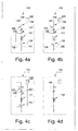
- 3a to 3d show the first system group 101 in different phases during Add a first secondary liquid. From these representations it can be seen that this system group 101 together with the storage container 110 and the buffer store 111, a ventilation device 114, a control device 115, a Level sensor 117, a first pneumatic control valve 118, a second pneumatic Control valve 120 and various other valves.
- FIG. 3a shows the system group 101 at the beginning of the metering process.
- the one with the first secondary liquid filled buffer 111 is via the open pressure control valve 118 connected to the source of positive pressure.
- the buffer is available 111 under pressure and is forcibly emptied.
- the control device 115 is provided, which is connected to the pressure control valve 118.
- the capacitive level sensor 117 is connected, via which the Decrease in secondary liquid per unit of time recorded and by means of the control device 115 can be kept at a predetermined value.
- the decrease Secondary fluid per unit of time corresponds directly to that of the main fluid per unit of time amount of secondary liquid added.
- the amount to be added per unit time depends Amount of first secondary liquid depends on several parameters. On the one hand the flow rate of the main liquid must be taken into account. On the other hand it depends on the desired ratio between the main liquid and Secondary fluid.
- 3b shows the state of the system group 101 towards the end of the metering process.
- 3c shows the system group 101 in a snapshot when filling of the buffer 111 can be seen.
- the valve 123 at the outlet of the Buffer 111 switched to pass while intake valve 124 was switched to lock, so that the buffer 111 over the line 126 is connected to the reservoir 110 and from this again with secondary liquid can be replenished.
- the reservoir 110 is under positive pressure set so that the first secondary liquid is forcibly in the buffer 111 is directed.
- the ventilation device 114 the flow through the Secondary liquid displaced air escape from the intermediate storage 111.
- Fig. 3d the system group is shown in the starting position, in which the Buffer 111 is again filled with the first secondary liquid and for a next batch is ready.
- 4a to 4d show the second system group 103 in different phases when adding a second secondary liquid.
- Pump 132 is through the input actuator 108 connected to the main liquid source.
- the pump 132 is not from the by-liquid is flowed through, but that an overpressure or underpressure exerted by the pump 132 Transfer to the secondary liquid via the mediating medium -water , and a filling or emptying of the buffer memory 131 is effected.
- the two media can be water and secondary liquid can be separated, for example by means of an air bubble. The Means for generating an air bubble are not shown in detail.
- FIG. 4a shows the system group 103 in the starting position, in which the metering spiral 131 is filled with secondary liquid.
- the emptying of the metering spiral 131 takes place by activating the pump 132.
- the mediating medium transmits the pressure difference built up by the pump 132 to that in the metering spiral 131 absorbed secondary fluid.
- the delivery rate of the pump 132 is by means of regulated electronics not shown here. If a reciprocating pump is used, the addition of the second can be done via the number of strokes per time Auxiliary fluid can be controlled. However, a regulation is also conceivable in which the fill level of the metering spiral 131 is measured and used as the actual value.
- main liquid in the present case water.
- This turns the metering spiral 131 into a mixing valve leading line 142 rinsed with water and residual liquid residues exempted.
- This rinsing is particularly important if the Dosing spiral 131 to the mixing valve line 142 various secondary liquids can be supplied, such as in the fourth system group 107 (Fig. 2) is possible.
- This rinsing process is designed so that the Line 142 completely of the secondary liquid used for the corresponding batch was liberated, however, care is taken that ultimately only one very small amount of rinsing liquid gets into the vessel 102.
- FIG. 4c shows the system group when filling the metering spiral 131 first the two valves 137, 138 switched over and the drain valve 133 open.
- a vacuum is now generated by means of the pump 132, so that the second Secondary liquid is sucked from the reservoir 130 into the metering spiral 131.
- the maximum fill level of the metering spiral 131 can be reached, for example, by means of an optical sensor can be monitored. Via the open drain valve 133 both parts of the line can be vented and residual liquid can be drained off.
- the system group 103 is shown in the starting position, in which the metering spiral 131 is in turn filled with the second secondary liquid.
- the arrangements described above provide maximum flexibility achieved in terms of the possible composition of the final product.
- the second embodiment provides a simpler, cheaper Variant, which is particularly suitable for metering in secondary liquids to one that is not or only under a slight positive pressure Main liquid is suitable.
- the second embodiment is particularly suitable also for dosing very small amounts of secondary liquids.
Landscapes
- Chemical & Material Sciences (AREA)
- Chemical Kinetics & Catalysis (AREA)
- Engineering & Computer Science (AREA)
- Mechanical Engineering (AREA)
- Accessories For Mixers (AREA)
- Non-Alcoholic Beverages (AREA)
Abstract
Es wird ein Verfahren und eine Anordnung zum chargenweisen Erzeugen eines durch zumindest eine Hauptflüssigkeit und zumindest eine Nebenflüssigkeit gebildeten Endprodukts vorgeschlagen. Die der strömenden Hauptflüssigkeit zuzudosierenden Nebenflüssigkeiten werden vor dem Zudosieren von einem Hauptspeicher (22, 33, 48, 53, 58) in einen Förderspeicher (28, 37, 50, 55, 60) überführt. Jede Nebenflüssigkeit wird mittels eines zugeordneten, nach dem Verdrängerprinzip arbeitenden Fördermittels (25, 34, 49, 54, 59) gefördert. Die Fördermittel (25, 34, 49, 54, 59) werden hydraulisch betätigt, wobei als Hydraulikflüssigkeit das gleiche Medium wie als Hauptflüssigkeit verwendet wird. Zum Vermischen der Hauptflüssigkeit mit den Nebenflüssigkeiten ist ein Mischelement (2) vorgesehen, wobei die Hauptflüssigkeit unter Überdruck steht, da sie mit Kohlensäure versetzt sein kann. Die Nebenflüssigkeiten werden dem Mischelement (2) daher unter einem Druck zugeführt, der höher ist als derjenige der Hauptflüssigkeit im Mischelement (2). <IMAGE>A method and an arrangement for the batchwise generation of an end product formed by at least one main liquid and at least one secondary liquid are proposed. The secondary liquids to be metered into the flowing main liquid are transferred from a main store (22, 33, 48, 53, 58) to a delivery store (28, 37, 50, 55, 60) before metering in. Each secondary liquid is conveyed by means of an associated conveying means (25, 34, 49, 54, 59) that works according to the displacement principle. The conveying means (25, 34, 49, 54, 59) are operated hydraulically, the same medium being used as the hydraulic fluid as the main fluid. A mixing element (2) is provided for mixing the main liquid with the secondary liquids, the main liquid being under excess pressure, since it can be carbonated. The secondary liquids are therefore fed to the mixing element (2) under a pressure which is higher than that of the main liquid in the mixing element (2). <IMAGE>
Description
Die Erfindung betrifft ein Verfahren zum chargenweisen Erzeugen eines flüssigen
Endprodukts gemäss dem Oberbegriff des Anspruchs 1 sowie eine Anordnung zum
chargenweisen Erzeugen eines flüssigen Endprodukts gemäss dem Oberbegriff des
Anspruchs 23.The invention relates to a method for batchwise generation of a liquid
End product according to the preamble of
Da ein derartiges Verfahren beispielsweise in Getränkeautomaten Anwendung finden kann, soll die grundsätzliche Problematik beim Erzeugen eines Getränks in einem Getränkeautomaten geschildert werden. Derartige Verfahren können beispielsweise in herkömmlichen Getränkeautomaten zur Anwendung kommen, bei denen ein kaltes oder warmes Endprodukt in ein offenes Gefäss wie beispielsweise einen Becher abgefüllt wird. Ebenso kann das Verfahren auch zum Abfüllen von Getränkeflaschen eingesetzt werden, wobei sowohl kohlensäurehaltige Getränke wie auch sogenannt "stille Wasser" erzeugt werden können. Ein grundsätzlicher Nachteil der den meisten bisher eingesetzten Getränkeautomaten anhaftet ist darin zu sehen, dass die verwendeten Flüssigkeiten und/oder Zusatzstoffe im Endprodukt, also im fertigen Getränk, nicht homogen miteinander vermischt sind. Bei Verwendung von Zusatzstoffen in Form von Pulver kann dies beispielsweise daher rühren, dass das Pulver nicht vollständig in der Hauptflüssigkeit -Wasser- gelöst wurde.Since such a method is used, for example, in vending machines for drinks can, should the basic problem when producing a drink in one Vending machines are described. Such methods can, for example are used in conventional vending machines where a cold or warm end product is filled into an open container such as a cup becomes. The method can also be used to fill beverage bottles are used, both carbonated drinks and so-called "still water" can be generated. A fundamental disadvantage of most Beverage vending machines previously used can be seen in the fact that the used Liquids and / or additives in the final product, i.e. in the finished beverage, are not homogeneously mixed together. When using additives in the form of powder, for example, this can be because the powder is not was completely dissolved in the main liquid -water-.
Aber auch wenn die Zusatzstoffe in flüssiger Form zugeführt werden, besteht die Gefahr, dass das Endprodukt keine homogene Mischung in Bezug auf die verwendeten Flüssigkeiten darstellt. Dies kann verschiedene Ursachen haben, indem beispielsweise die verschiedenen Flüssigkeiten dem Becher separat zugeführt werden.But even if the additives are added in liquid form, there is Danger that the end product is not a homogeneous mixture with respect to the used Represents liquids. This can have various causes, for example the different liquids are fed into the cup separately.
Es versteht sich, dass ein Endprodukt, bei dem die einzelnen Bestandteile nicht homogen miteinander vermischt sind, Mängel in bezug auf die gewünschte Qualität offenbart. Einerseits kann dies darin bestehen, dass das Getränk dem Konsumenten geschmacklich nicht zusagt. Andererseits können gewisse Inhomogenitäten auch visuell wahrgenommen werden.It is understood that an end product in which the individual components are not homogeneous are mixed together, defects in the desired quality disclosed. On the one hand, this can be that the drink is the consumer tastes not appealing. On the other hand, certain inhomogeneities can also occur be perceived visually.
Aus der EP 0 479 113 ist eine Vorrichtung zum Herstellen von Getränken aus wenigstens zwei flüssigen Komponenten bekannt. Zum Abmessen vorgegebener Mengen der Komponenten sind mehrere Dosierbehälter vorgesehen, deren Auslässe über einen Mischkanal in einen Sammelbehälter münden. Der Dosierbehälter der grössten Komponente ist als Überlaufbehälter ausgebildet. Sein Inhalt strömt beim Mischvorgang, der Schwerkraft folgend, durch die Dosierbehälter der kleineren Komponenten. Die Komponenten in den kleineren Behältern werden durch Einstellen vorgegebener Füllhöhen abgemessen.EP 0 479 113 describes a device for producing beverages from at least one known two liquid components. For measuring specified quantities of the components several dosing containers are provided, their outlets open into a collecting container via a mixing channel. The dosing container of the largest component is designed as an overflow container. Its content flows with Mixing process, following gravity, through the dosing containers of the smaller components. The components in the smaller containers are adjusted specified filling levels.
Aus der EP 0 443 837 ist ein Verfahren und eine Vorrichtung zum Abmessen und Vermischen eines aus zwei Komponenten bestehenden Getränks bekannt. Zum Ermitteln der proportionalen Vermischung wird der Massenfluss der in eine Proportioniereinrichtung einfliessenden Komponenten herangezogen. Dabei wird der Massenfluss mittels Massendurchflussmessern ermittelt.EP 0 443 837 describes a method and a device for measuring and Mixing a beverage consisting of two components known. To determine The proportional mixing becomes the mass flow into a proportioning device inflowing components. The mass flow determined by means of mass flow meters.
In der EP 0 152 283 ist ein Getränkedispenser beschrieben. Zum Vermischen einer ersten mit einer zweiten Komponente weist dieser eine Doppelkolbenpumpe mit unterschiedlich dimensionierten, mechanisch miteinander gekoppelten Kolben auf. Im einen Zylinder ist eine vorgespannte, den Kolben belastende Feder vorgesehen. Der eine, obere Zylinderraum kann über ein elektromagnetisch betätigtes Ventil mit einer Frischwasserquelle verbunden werden. Der andere, untere Zylinderraum ist über ein Rückschlagventil mit einem ein Konzentrat enthaltenden Behälter verbunden. Wenn der obere Zylinderraum über das elektromagnetisch betätigte Ventil mit der Frischwasserquelle verbunden wird, werden die beiden Kolben durch das unter Überdruck stehende und in den oberen Zylinderraum einfliessende Frischwasser entgegen der Kraft der Feder hochgefahren. Dabei füllt sich der untere Zylinderraum mit Konzentrat. Wenn dann die beiden Kolben durch die Kraft der Feder nach unten bewegt werden, entleeren sich beide Zylinderräume. Dabei werden die aus den beiden Zylinderräumen austretenden Flüssigkeiten in einem festen, durch die Querschnittsfläche der Zylinderräume bestimmten Verhältnis miteinander vermischt.A beverage dispenser is described in EP 0 152 283. To mix one The first with a second component has a double piston pump with different dimensioned, mechanically coupled pistons. in the a biased spring loading the piston is provided in a cylinder. The An upper cylinder chamber can be connected to an electromagnetically operated valve Fresh water source can be connected. The other, lower cylinder space is over one Check valve connected to a container containing a concentrate. If the upper cylinder chamber via the electromagnetically operated valve with the fresh water source is connected, the two pistons are pressurized by the standing fresh water flowing into the upper cylinder chamber against the Force raised by the spring. The lower cylinder space fills with concentrate. Then when the two pistons are moved down by the force of the spring both cylinder spaces empty. The two cylinder rooms leaking liquids in a solid, through the cross-sectional area the ratio determined by the cylinder spaces mixed together.
Aus der WO 90/02702 ist ein Getränkedispenser bekannt, der ebenfalls mit einer Doppelkolbenpumpe versehen ist, deren Kolben mittels einer Feder vorgespannt sind. Der eine Zylinderraum dieser Doppelkolbenpumpe dient der Aufnahme von Wasser, währenddem der andere Zylinderraum zur Aufnahme von Sirup vorgesehen ist. Die Betätigung der Kolben entgegen der Vorspannkraft der Feder erfolgt durch Beaufschlagung des grösseren Kolbens mit einem Kohlendioxydgas. Dabei wird sowohl das sich im einen Zylinderraum befindliche Wasser wie auch der sich im anderen Zylinderraum befindliche Sirup über je eine Leitung zu einem Getränkebehälter gefördert. Das geförderte Wasser wird dabei in einem Mischventil zusätzlich mit Kohlendioxydgas angereichert. A beverage dispenser is known from WO 90/02702, which also has a Double piston pump is provided, the piston of which is biased by a spring are. One cylinder chamber of this double piston pump is used to hold Water, while the other cylinder room is intended to hold syrup is. The pistons are actuated against the preload force of the spring by Actuation of the larger piston with a carbon dioxide gas. Both the water in one cylinder space as well as the water in the other Syrup located in the cylinder space via a line to a beverage container promoted. The pumped water is also included in a mixing valve Enriched with carbon dioxide gas.
Ausgehend vom beschriebenen Stand der Technik liegt der Erfindung die Aufgabe
zugrunde, ein Verfahren gemäss dem Oberbegriff des Anspruchs 1 derart zu verbessern,
dass eine hohe und gleichbleibende Qualität des Endprodukts sichergestellt
und andererseits eine hohe Flexibilität in Bezug auf die Grösse und/oder Zusammensetzung
der Charge erreicht werden kann.Starting from the described prior art, the object of the invention
to improve a method according to the preamble of
Diese Aufgabe wird durch die im Kennzeichen des Anspruchs 1 angeführten Verfahrensschritte
gelöst.This object is achieved by the method steps specified in the characterizing part of
Bevorzugte Verfahrensformen sind in den abhängigen Ansprüchen 2 bis 22 umschrieben.Preferred forms of process are described in the
Bei einer bevorzugten Verfahrensform wird die Nebenflüssigkeit vor dem Zudosieren von einem Hauptspeicher in einen Förderspeicher überführt. Dadurch wird die Voraussetzung für eine genaue und reproduzierbare Dosierung geschaffen.In a preferred form of the process, the secondary liquid is added before metering transferred from a main storage to a conveyor storage. This becomes the requirement created for an exact and reproducible dosage.
Bei einer weiteren bevorzugten Verfahrensform steht die Hauptflüssigkeit bzw. stehen die Hauptflüssigkeiten unter Überdruck und wird/werden durch ein Mischelement geleitet und die Nebenflüssigkeit(en) werden dem Mischelement unter einem Druck zugeführt, der höher ist als derjenige der Hauptflüssigkeit(en) im Mischelement. Dadurch wird beispielsweise die Voraussetzung zur Herstellung eines kohlensäurehaltiges Endprodukts -Getränk- geschaffen.In a further preferred form of the process, the main liquid or liquids are the main fluids are under pressure and are / will be through a mixing element passed and the secondary liquid (s) are the mixing element under a pressure supplied, which is higher than that of the main liquid (s) in the mixing element. Thereby becomes, for example, the requirement for the production of a carbonated End product -drink- created.
Eine weitere Aufgabe der Erfindung besteht darin, die im Oberbegriff des Anspruchs
23 beschriebene Anordnung derart zu verbessern, dass wiederum eine hohe und
gleichbleibende Qualität des Endprodukts sichergestellt und eine hohe Flexibilität in
Bezug auf die Grösse und/oder Zusammensetzung der Charge erreicht werden kann.Another object of the invention is that in the preamble of the
Diese Aufgabe wird durch die im Kennzeichen des Anspruchs 23 angeführten Merkmale
gelöst. Bevorzugte Ausführungsformen der Anordnung sind in den abhängigen
Ansprüchen 24 bis 45 umschrieben.This object is achieved by the features stated in the characterizing part of
Anhand von Zeichnungen wird nachfolgend ein bevorzugtes Ausführungsbeispiel der Erfindung näher erläutert. In diesen Zeichnungen zeigt:
- Fig. 1
- eine Anordnung zum Zudosieren von mehreren Nebenflüssigkeiten zu einer strömenden Hauptflüssigkeit in schematischer Darstellung;
- Fig. 2
- eine alternative Anordnung zum Zudosieren von mehreren Nebenflüssigkeiten zu einer strömenden Hauptflüssigkeit in schematischer Darstellung;
- Fig. 3a bis 3d
- eine erste Systemgruppe der in der Fig. 2 dargestellten Anordnung zum Zudosieren einer ersten Nebenflüssigkeit während verschiedenen Phasen, und
- Fig. 4a bis 4d
- eine weitere Systemgruppe der in der Fig. 2 dargestellten Anordnung zum Zudosieren einer weiteren Nebenflüssigkeit während verschiedenen Phasen.
- Fig. 1
- an arrangement for metering several secondary liquids to a flowing main liquid in a schematic representation;
- Fig. 2
- an alternative arrangement for metering several secondary liquids to a flowing main liquid in a schematic representation;
- 3a to 3d
- a first system group of the arrangement shown in FIG. 2 for metering a first secondary liquid during different phases, and
- 4a to 4d
- another system group of the arrangement shown in FIG. 2 for metering a further secondary liquid during various phases.
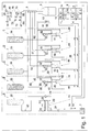
Anhand der Figur 1, welche eine erste Ausführungsform einer Anordnung zum Zudosieren
von mehreren Nebenflüssigkeiten zu einer strömenden Hauptflüssigkeit in
schematischer und nicht massstabsgetreuer Darstellung zeigt, wird der grundsätzliche
Aufbau der Anordnung näher erläutert. Die gezeigte Anordnung bildet im vorliegenden
Fall einen Teil eines Getränkeautomaten zum Ab- bzw. Auffüllen von Getränkeflaschen
3. Durch das erfindungsgemässe Verfahren bzw. die Anordnung zur
Durchführung des Verfahrens soll dem Benutzer einerseits ermöglicht werden, Flaschen
mit unterschiedlichem Inhalt, beispielsweise 0.3 bis 2 Liter abzufüllen. Andererseits
soll der Benutzer die Zusammensetzung des Getränks, namentlich dessen
Geschmack sowie ggf. dessen Inhaltsstoffe, weitgehend selber bestimmen können.
Als Hauptflüssigkeit wird im vorliegenden Fall Wasser verwendet, währenddem als
Nebenflüssigkeiten insbesondere Zuckersirup, Aromastoffe, Farbstoffe und Wertstoffe
wie beispielsweise Vitamine und Ballaststoffe vorgesehen sind.1, which shows a first embodiment of an arrangement for metering
from several secondary liquids to a flowing main liquid in
shows schematic and not to scale, the basic
Structure of the arrangement explained in more detail. The arrangement shown forms here
Case a part of a drinks machine for filling or filling
Zum Erzeugen eines für den Betrieb der Anordnung notwendigen hydraulischen
Steuerdrucks ist ein Hydraulikaggregat 1 vorgesehen. Allerdings ist es keinesfalls
zwingend, dass das Hydraulikaggregat 1 Teil der Anordnung ist, sondern dieses
könnte ebensogut auch ausserhalb der Anordnung dezentral angeordnet werden. Im
weiteren sind zwei Steuervorrichtungen 4, 11, eine Ventilmatrix 20, mehrere Systemgruppen
A, B, C, D, E zum Zudosieren von verschiedenen Nebenflüssigkeiten, Zufuhrleitungen
67, 72 zum Zuführen von Hauptflüssigkeiten, eine Zufuhrleitung 76 zum
Zuführen eines Gases sowie ein Mischelement 2 zum Vermischen der Hauptflüssigkeit(en)
mit den Nebenflüssigkeiten vorgesehen. Jede Systemgruppe A, B, C, D, E ist
mit einem volumetrisch arbeitenden, hydraulisch betätigten Fördermittel 25, 34, 49,
54, 59 versehen. Als Hydraulikmedium wird im vorliegenden Fall ebenfalls Wasser
verwendet.To generate a hydraulic necessary for the operation of the arrangement
Control pressure, a
Die Steuervorrichtungen 4, 11 verfügen über je einen in einem Zylinder 5, 12 angeordneten
Kolben 6, 13, welche Kolben 6, 13, auf die vorliegende Zeichnung bezogen,
nach links und nach rechts verschiebbar sind. Beide Steuervorrichtungen 4, 11 sind
hydraulisch mit dem Hydraulikaggregat 1 verbunden und zur Ansteuerung des jeweiligen
Kolbens 6, 13 mit einer Mehrzahl von fremdbetätigten Ventilen versehen, wobei
auf die entsprechenden Leitungen und Ventile nicht im einzelnen eingegangen wird,
da deren grundsätzliche Funktionsweise bekannt ist. Die beiden Steuervorrichtungen
4, 11 sind über die Ventilmatrix 20 hydraulisch mit den Systemgruppen B, C, D, E
verbunden. Mittels dieser Ventilmatrix 20, welche im vorliegenden Fall acht fremd-betätigte
Ventile umfasst, können die Systemgruppen B, C, D, E hydraulisch individuell
angesteuert werden, wobei jeweils zwei Systemgruppen gleichzeitig angesteuert
werden können. Auf der Aussenseite der Steuervorrichtungen 4, 11 ist je ein
Weggeber 8, 15 angeordnet. Jeder Weggeber 8, 15 ist an einer entsprechenden Erfassungselektronik
9, 16 angeschlossen. Die beispielsweise auf dem magnetostriktiven
Prinzip arbeitenden Weggeber 8, 15 dienen der Erfassung der Position des Kolbens
6, 13. Um den auf die Primärseite der Kolben 6, 13 der Steuervorrichtungen 4,
11 einwirkenden Druck beeinflussen zu können, sind zwei Proportionalventile 18, 19
vorgesehen. Es versteht sich, dass eine Steuer- und Erfassungselektronik zum Ansteuern
der vorgesehenen Komponenten wie den genannten Ventilen vorgesehen
ist. Ausserdem dient die Steuer- und Erfassungselektronik auch dem Auswerten der
von den Sensoren -Weggeber 8, 15- abgegebenen Signale. Auf die Darstellung dieser
Steuer- und Erfassungselektronik mitsamt den zugehörigen elektrischen Leitungen
wurde zugunsten einer übersichtlichen Darstellung verzichtet.The
Die erste Systemgruppe A ist mit einem Vorratsbehälter 22 zur Aufnahme einer ersten
Nebenflüssigkeit versehen. Im vorliegenden Fall besteht die erste Nebenflüssigkeit
aus Zuckersirup. Zur Förderung der ersten Nebenflüssigkeit vom Vorratsbehälter
22 zum Fördermittel 25 ist eine Pumpe 23 vorgesehen. Das als Kolbenförderer 25
ausgebildete Fördermittel dient dem exakten Zudosieren der ersten Nebenflüssigkeit
und dem zwangsweisen Zuführen dieser ersten Nebenflüssigkeit zu dem Mischelement
2. Der Kolbenförderer 25 ist dazu mit einem Zylinder 26 und einem darin angeordneten,
in beide Richtungen verschiebbaren Kolben 27 versehen. Der rechts des
Kolbens 27 liegende Zylinderraum 28 dient als Förderspeicher zur Aufnahme der zuzudosierenden
Nebenflüssigkeit. Auf der Aussenseite des Kolbenförderers 25 ist
wiederum ein Weggeber 29 angeordnet, der an einer entsprechenden Erfassungselektronik
30 angeschlossen ist. Diese erste Systemgruppe A ist über eine Leitung
31 mit dem Mischelement 2 verbunden. Zum Kühlen der im Vorratsbehälter 22 aufgenommenen
Nebenflüssigkeit kann ggf. ein Kühlaggregat vorgesehen werden.
Ebenso können Mittel zum Umwälzen der im Vorratsbehälter 22 aufgenommenen
Nebenflüssigkeit vorgesehen werden, damit die Homogenität dieser Nebenflüssigkeit
gewährleistet ist. Die erwähnten Mittel sind jedoch nicht näher dargestellt.The first system group A has a storage container 22 for receiving a first one
Provide secondary liquid. In the present case there is the first secondary liquid
made from sugar syrup. To pump the first secondary liquid from the
Die zweite Systemgruppe B weist einen mit einer zweiten Nebenflüssigkeit gefüllten
Vorratsbehälter 33 auf. Im Gegensatz zur ersten Systemgruppe A ist in diesem Fall
jedoch keine Pumpe vorgesehen. Der Vorratsbehälter 33 ist mit einem über die
Steuervorrichtungen 4, 11 betätigbaren Hubkolbenförderer 34 versehen. Der Hubkolbenförderer
34 weist zwei über eine Kolbenstange verbundene Kolben 35, 36 auf.
Der untere Kolben 35 wird nachfolgend als Betätigungskolben bezeichnet währenddem
der obere Kolben 36 als Dosierkolben bezeichnet wird. Der Betätigungskolben
35 kann über die Steuervorrichtungen 4, 11 sowohl nach oben wie auch nach unten
bewegt werden, wobei die dazu vorgesehenen Leitungen und Ventile nicht näher
erläutert werden. Der über dem Dosierkolben 36 angeordnete Dosierraum 37 dient
als Förderspeicher, mittels welchem die zuzudosierende Nebenflüssigkeit volumetrisch
dosiert und dem Mischelement 2 über eine Leitung 46 zwangsweise zugeführt
werden kann. Das von der Hauptflüssigkeit -Wasser- durchströmte Mischelement
2 dient dem Durchmischen der Hauptflüssigkeit mit den Nebenflüssigkeiten. Die
Ventilmatrix 20 ermöglicht das individuelle Ansteuern von weiteren, den einzelnen
Systemgruppen B, C, D, E zugeordneten Hubkolbenförderern 49, 54, 59. Sowohl in
der Leitung 46 wie auch in der Verbindungsleitung zwischen dem Vorratsbehälter 33
und dem Hubkolbenförderer 34 ist je ein Rückschlagventil 38, 39 angeordnet, auf
deren Wirkungsweise jedoch ebenfalls nicht näher eingegangen wird. Ausserdem
weist die Systemgruppe B zwei hydraulische Zuleitungen 40, 41, und zwei hydraulische
Abführleitungen 42, 43 auf. Vom jeweiligen Zwischenspeicher 50, 55, 60 der
übrigen Systemgruppen C, D, E führt ebenfalls je eine Leitung 52, 57, 62 zum Mischelement
2. Diese Leitungen 52, 57, 62 münden an unterschiedlichen Stellen entlang
einer Mischstrecke in das von der Hauptflüssigkeit durchströmte Mischelement 2.The second system group B has one filled with a second secondary
Da die weiteren Systemgruppen C, D, E baugleich mit der zweiten Systemgruppe B sind, wird auf deren Ausgestaltung nicht näher eingegangen. Since the other system groups C, D, E are identical in construction to the second system group B are not discussed in more detail on their design.
Zum Zuführen der Hauptflüssigkeit in Form von Wasser sind zwei Zufuhrleitungen
67, 72 vorgesehen. Über die eine Leitung 67 wird stilles Wasser zugeführt, währenddem
über die andere Leitung 72 karbonisiertes Wasser zugeführt wird. Beide Leitungen
67, 72 sind mit je einem Durchflussmesser 68, 73, einem fremdbetätigten Proportionalventil
69, 74 sowie einem Rückschlagventil 70, 75 versehen. Die beiden
Durchflussmesser 68, 73, wie auch die beiden Proportionalventile 69, 74 sind ebenfalls
mit der nicht näher dargestellten Steuerelektronik verbunden. Über die Leitung
76 kann ein unter Druck stehendes Gas zum pneumatischen Vorspannen der Getränkeflasche
3 zugeführt werden, wobei in der Leitung 76 ein weiteres, fremdbetätigtes
Proportionalventil 77 sowie ein Flüssigkeitsabscheider 78 angeordnet sind.There are two supply lines for supplying the main liquid in the form of
Die Funktionsweise und der Verfahrensablauf der Anordnung stellen sich wie folgt dar:The mode of operation and the procedural sequence of the arrangement are as follows represents:
Nachdem der Benutzer über eine Bedieneinheit die Getränkezusammensetzung bestimmt
hat und die Getränkeflasche 3 an der dafür vorgesehenen Stelle platziert
wurde, wird diese auf Dichtheit überprüft, indem die Getränkeflasche 3 über die Leitung
76 unter Druck gesetzt und danach festgestellt wird, ob der Druck über einen
bestimmten Zeitraum, beispielsweise einige Sekunden, konstant bleibt, bzw. ob ein
maximal vorgegebenen Druckabfall nicht überschritten wird. Für diese Dichteprüfung
wie auch das nachfolgende Vorspannen der Getränkeflasche 3 wird vorzugsweise
ein Gas wie Stickstoff (N2) oder Kohlensäure (CO2) verwendet. Ausserdem wird die
Grösse -Inhalt- der Getränkeflasche, beispielweise mittels eines optischen Sensors,
festgestellt bzw. mit einer allfälligen Vorgabe überprüft.After the user has determined the beverage composition via an operating unit and the
Auf die Darstellung eines Benutzerinterfaces -Bedienpanel-, mittels welchem der Benutzer des Getränkeautomaten sein Getränk auswählen bzw. zusammenstellen kann, wurde verzichtet. Es ist beispielsweise denkbar, dass die Zusammensetzung des Getränks menugesteuert mittels eines vom Benutzer bedienbaren "Touch-Screen" Bildschirms erfolgen kann. Der Benutzer kann dabei beispielsweise die Flaschengrösse, die Art und Basis des Süssstoffs, den Geschmack des fertigen Getränks sowie allfällige Zusatzstoffe wie beispielsweise Ballaststoffe und Vitamine innerhalb bestimmter Grenzen selber bestimmen. Nachdem die Zusammensetzung des Getränks bestimmt wurde, wird über einen nicht näher dargestellten Rechner die Menge der Haupt- sowie der einzelnen Nebenflüssigkeiten errechnet, die für das gewünschte Gesamtvolumen der Charge benötigt werden. On the display of a user interface control panel, by means of which the user the beverage machine selects or compiles its beverage can, was waived. For example, it is conceivable that the composition the drink is menu-controlled by means of a "touch screen" that can be operated by the user Screen can be done. The user can, for example, determine the bottle size, the type and basis of the sweetener, the taste of the finished drink as well as any additives such as fiber and vitamins within determine certain limits yourself. After the composition of the drink was determined, the computer is not shown Amount of the main and the individual secondary liquids calculated for the desired Total volume of the batch will be needed.
Danach wird der Füllvorgang gestartet, indem die Hauptflüssigkeit über die Leitung
67 oder 72 zugeführt wird. Durch Mischen der beiden Hauptflüssigkeiten kann dabei
auch der Gehalt an CO2 in weiten Grenzen variiert werden. Kurz nach dem Beginn
des Zuführens der Hauptflüssigkeit wird auch die Zufuhr der Nebenflüssigkeit bzw.
der Nebenflüssigkeiten gestartet. Die Anordnung ist so ausgelegt, dass sowohl der
Förderspeicher für die erste Nebenflüssigkeit -Zylinderraum 28 des Kolbenförderers
25- wie auch die Förderspeicher für die weiteren Nebenflüssigkeiten -Dosierzylinder
37, 50, 55, 60 der Hubkolbenförderer 34, 49, 54, 59- schon vor dem Beginn des Abfüllvorgangs
mit der jeweiligen Nebenflüssigkeit gefüllt sind. Zum Zudosieren der
ersten Nebenflüssigkeit -Zuckersirup- wird das Ventil 24 geöffnet, wodurch der Kolben
27 des Kolbenförderers 25 nach rechts verschoben wird. Die sich im Dosierzylinder
28 des Kolbenförderers 25 befindliche Nebenflüssigkeit wird über die Leitung
31 dem Mischelement 2 zugeführt, wo es über ein Rückschlagventil in dessen Innenraum
gelangt und sich mit der durchströmenden Hauptflüssigkeit vermischt.The filling process is then started by supplying the main liquid via
Zeitgleich mit dem Zudosieren der ersten Nebenflüssigkeit wird auch die weitere Nebenflüssigkeit
bzw. werden die weiteren Nebenflüssigkeiten zudosiert. Je nach Auslegung
der Anordnung können die Nebenflüssigkeiten kontinuierlich oder in Intervallen
zugeführt werden. Indem das Verschieben -Hub- des Kolbens 27 des Kolbenförderers
25 sowie der Kolben 6, 13 der beiden Steuervorrichtungen 4, 11 mittels des
zugeordneten Weggebers 29; 8, 15 erfasst wird, kann eine genaue Zudosierung der
jeweiligen Nebenflüssigkeit erreicht werden, da aus dem Kolbenhub und der bekannten
Zylinder-Querschnittsfläche das entsprechende Volumen errechnet werden
kann. Derartige, nach dem Verdrängerprinzip arbeitende Fördermittel mit volumetrischer
Zudosierung bieten sich insbesondere dann an, wenn unterschiedlichen Nebenflüssigkeiten
mit zumindest teilweise unterschiedlichen Viskositäten gefördert
werden müssen. Durch Umschalten der der jeweiligen Steuervorrichtung 4, 11 zugeordneten
Ventile können beide Verschiebrichtungen der Kolben 6, 13 zum hydraulischen
Ansteuern der Systemgruppen B, C, D, E genutzt werden.At the same time as the first secondary liquid is added, the further secondary liquid also becomes
or the other secondary liquids are metered in. Depending on the design
The secondary liquids can be arranged continuously or at intervals
be fed. By moving -hub- the
Im vorliegenden Fall sind Förderspeicher 37, 50, 55, 60 vorgesehen, die eine in Relation
zum Vorratsbehälter sehr geringe Menge an Nebenflüssigkeit aufnehmen können.
Vorzugsweise sind die Förderspeicher 37, 50, 55, 60 so ausgelegt, dass sie
zumindest die maximal pro Charge zuzudosierende Menge an Nebenflüssigkeit aufnehmen
können. Durch das Vorsehen solcher Förderspeicher 37, 50, 55, 60 wird die
Voraussetzung geschaffen, damit die entsprechende Nebenflüssigkeit sehr genau
zudosiert werden kann.In the present case, conveyor stores 37, 50, 55, 60 are provided, which are in relation
can hold a very small amount of secondary liquid to the reservoir.
The conveyor stores 37, 50, 55, 60 are preferably designed such that they
Take up at least the maximum amount of secondary liquid to be added per batch
can. By providing
Durch das Vorsehen einer Ventilmatrix können mit den zwei vorgesehenen Steuervorrichtungen zwei Hubkolbenförderer angesteuert und damit zwei Nebenflüssigkeiten gleichzeitig zudosiert werden. Es versteht sich, dass sowohl die Anzahl der Steuervorrichtungen wie auch die Anzahl der Hubkolbenförderer je nach Aufgabenstellung beliebig verändert werden kann.By providing a valve matrix, the two control devices provided can be used controlled two reciprocating piston conveyors and thus two secondary liquids be metered in at the same time. It is understood that both the number of control devices as well as the number of reciprocating piston conveyors depending on the task can be changed at will.
Damit das zum Betätigen der Fördermittel 25, 34, 49, 54, 59 verwendete Wasser
auch hohen hygienischen Anforderungen genügt, wird dieses regelmässig erneuert.
Das Hydraulikwasser wird funktionsbedingt über die beiden oberhalb des Auffangbehälters
65 angeordneten Ventile 63, 64 abgelassen. Bei den Hubkolbenförderern 34,
49, 54, 59 wird mit jedem Verschieben des Kolbens das vom Betätigungskolben 35
auf der druckabgewandten Seite verdrängte Wasser abgelassen, da die Ventile 63,
64 zum entsprechenden Zeitpunkt geöffnet werden. Ebenso kann das Hydraulikwasser
natürlich periodisch ausgetauscht werden, indem die beiden Ventile 63, 64 im
Ruhezustand der Hubkolbenförderer 34, 49, 54, 59 geöffnet und die Leitungen dadurch
durchgespült werden. Analog verhält es sich beim Kolbenförderer 25. Auf
diese Weise wird ein gegen die Umgebungsatmosphäre abgeschlossenes System
mit abgeschlossenen Fördermitteln geschaffen, welche sehr hohen hygienischen
Anforderungen genügen.So that the water used to actuate the
Anstelle der gezeigten Kolbenförderer bzw. Hubkolbenförderer kann beispielsweise auch ein Membranförderer eingesetzt werden. Der Vorteil der gezeigten, nach dem Verdrängerprinzip arbeitenden Kolbenförderer bzw. Hubkolbenförderer besteht zum einen darin, dass damit die Nebenflüssigkeiten sehr genau zudosiert werden können, da bei solchen, nach dem Verdrängerprinzip arbeitenden Förderern kein Flüssigkeitsschlupf entsteht und der Kolbenhub daher direkt proportional zur Menge an zudosierter Nebenflüssigkeit ist. Zum anderen kann mit ihnen ein relativ hoher Förderdruck aufgebaut werden, der höher als der Systemdruck der durch das Mischelement strömenden Hauptflüssigkeit ist. Indem als Hydraulikflüssigkeit das gleiche Medium wie als Hauptflüssigkeit -Wasser- verwendet wird, hat auch ein allfälliges "Kontaminieren" der Nebenflüssigkeit(en) mit der Hydraulikflüssigkeit keine negativen Folgen.Instead of the piston conveyor or reciprocating piston conveyor shown, for example a membrane conveyor can also be used. The advantage of the shown, after Displacement principle working piston conveyor or reciprocating piston conveyor exists for one in that the secondary liquids can be metered in very precisely, there is no liquid slippage with such conveyors working on the displacement principle arises and the piston stroke is therefore directly proportional to the amount of metered Secondary fluid is. On the other hand, they can handle a relatively high delivery pressure be built up, which is higher than the system pressure by the mixing element main liquid is flowing. By using the same medium as hydraulic fluid How is used as the main liquid - water - also has a possible "contamination" the secondary fluid (s) with the hydraulic fluid no negative consequences.
Mit der beschriebenen Anordnung kann eine genaue und reproduzierbare Dosierung
von einer oder mehreren Nebenflüssigkeiten, volumen- und zeitproportional zu einer
Hauptflüssigkeit, gegen erhöhten, nicht konstanten Druck unter verschärften hygienischen
Anforderungen erreicht werden. Beispielsweise eignet sich eine derartige Anordnung
auch zur Dosierung von faser- und/oder partikelhaltigen Nebenflüssigkeiten.
Ausserdem kann eine derartige Anordnung sehr einfach über die beiden oberhalb
des Auffangbehälters 65 angeordneten Ventile 63, 64 entlüftet werden.With the arrangement described, an accurate and reproducible dosage can
from one or more secondary liquids, proportional to volume and time to one
Main liquid, against increased, not constant pressure under tightened hygienic
Requirements are met. Such an arrangement is suitable, for example
also for dosing fiber and / or particle-containing secondary liquids.
In addition, such an arrangement can be very easily above the two above
the
Fig. 2 zeigt ein alternatives Ausführungsbeispiel eine Anordnung zum Zudosieren von mehreren Nebenflüssigkeiten zu einer strömenden Hauptflüssigkeit in schematischer Darstellung. Eine derartige Anordnung eignet sich beispielsweise für labortechnische, medizinische oder chemische Anwendungen, bei denen die Hauptflüssigkeit vorzugsweise nicht unter hohem Druck steht.Fig. 2 shows an alternative embodiment of an arrangement for metering from several secondary liquids to a flowing main liquid in a schematic Presentation. Such an arrangement is suitable, for example, for laboratory, medical or chemical applications in which the main liquid is preferably not under high pressure.
Die Anordnung weist eine Vielzahl von Systemgruppen 101, 103, 105, 107 auf. Jeder
Systemgruppe 101, 103, 105, 107 ist zumindest ein Vorratsbehälter 110, 130, 150,
170, 171, 172, 173 zur Aufnahme einer Nebenflüssigkeit zugeordnet. Im vorliegenden
Beispiel ist, von links gesehen, der ersten Systemgruppe ein Behälter 110 zur
Aufnahme einer ersten Nebenflüssigkeit, der zweiten Systemgruppe ein Behälter 130
zur Aufnahme einer zweiten Nebenflüssigkeit, der dritten Systemgruppe ein Behälter
150 zur Aufnahme einer dritten Nebenflüssigkeit und der vierten Systemgruppe mehrere
Behälter 170, 171, 172, 173 zur Aufnahme von weiteren Nebenflüssigkeiten zugeordnet.
Jeder Vorratsbehälter 110, 130, 150, 170, 171, 172, 173 ist mit einem Zwischenspeicher
111, 131, 151, 175, 176, 177, 178 verbunden, welcher vor dem Erzeugen
einer Charge mit der jeweiligen Nebenflüssigkeit aufgefüllt wird. Auch in diesem
Fall sind die Zwischenspeicher 111, 131, 151, 175, 176, 177, 178 dazu vorgesehen,
eine in Relation zum Vorratsbehälter sehr kleine Menge an Nebenflüssigkeit
aufzunehmen, wobei vorzugsweise wieder die maximal pro Charge zuzudosierende
Menge an Nebenflüssigkeit darin Aufnahme finden sollte. Es versteht sich, dass die
Anzahl und Anordnung der Vorratsbehälter 110, 130, 150, 170, 171, 172, 173 praktisch
ebenso beliebig variierbar ist, wie die Art und Menge der darin aufgenommenen
Flüssigkeiten.The arrangement has a multiplicity of
Eine zur Aufnahme des fertigen Gemischs vorgesehenes Gefäss 102 ist andeutungsweise
eingezeichnet. Oberhalb dieses Gefässes 102 ist eine Abfülleinrichtung
104 angeordnet. Die Abfülleinrichtung 104 weist ein Mischventil 140 auf, welches
über je eine Leitung 141, 142, 143, 144 mit den verschiedenen Systemgruppen 101,
103, 105, 107 verbunden ist. Über eine Leitung 145 kann Hauptflüssigkeit zugeführt
werden. Um ggf. die Durchflussrate der Hauptflüssigkeit erfassen zu können, ist ein
Durchflusssensor 149 vorgesehen.A
Der Zwischenspeicher der ersten Systemgruppe ist als zylindrischer Behälter 111
ausgebildet, dessen Grösse so gewählt ist, dass er zumindest diejenige Menge an
Nebenflüssigkeit aufnehmen kann, welche im Maximum für eine Charge benötigt
wird. Zum Fördern der ersten Nebenflüssigkeit ist ein Kompressor (nicht dargestellt)
vorgesehen, welcher über eine Leitung 112 mit dem Vorratsbehälter 110 oder über
eine Leitung 113 mit dem Zwischenspeicher 111 verbunden werden kann.The buffer of the first system group is a
Die zweite, dritte, und vierte Systemgruppe sind über je eine gemeinsame Leitung
106 und ein Regelventil 108 an einer weiteren Zufuhrleitung für Hauptflüssigkeit angeschlossen.The second, third and fourth system groups are each via a
Bei der zweiten und dritten Systemgruppe 103, 105 sind der Zwischenspeicher in
Form einer Dosierspirale 131, 151 ausgebildet. Zum Fördern der entsprechenden
Nebenflüssigkeit ist oberhalb des Zwischenspeichers 131, 151 jeweils eine Pumpe
132, 152 angeordnet. Über der Pumpe 132, 152 ist je ein Ablassventil 133, 153 angebracht,
dessen Funktion anschliessend noch erläutert wird. Ausserdem ist jeweils
eine Bypassleitung 135, 155 zur Umgehung der Dosierspirale 131, 151 vorgesehen.
Zur Aktivierung des Ablassventils 133, 153 der Bypassleitung 135, 155 sowie zum
Auffüllen und Entleeren des Zwischenspeichers 131, 151 sind pro Systemgruppe
103, 105 jeweils drei Ventile 136, 137, 138; 156, 157, 158 vorgesehen.In the second and
Die vierte Systemgruppe 107 ist mit insgesamt vier Vorratsbehältern 170, 171, 172,
173 zur Aufnahme von gattungsgleichen Nebenflüssigkeiten versehen. Jedem Vorratsbehälter
170, 171, 172, 173 ist ein Zwischenspeicher in Form einer Dosierspirale
175, 176, 177, 178 zugeordnet. Allerdings ist nur eine Pumpe 180 zum Fördern von
jeweils einer Nebenflüssigkeit pro Charge vorgesehen. Sämtliche Ein- und Auslässe
der Dosierspiralen 175, 176, 177, 178 sind über je eine gemeinsame Leitung 181,
182 miteinander verbunden. Auch bei dieser Systemgruppe 107 ist eine Bypassleitung
183 zur Umgehung der Dosierspiralen 175, 176, 177, 178 sowie ein Ablassventil
184 vorgesehen. Zum Auffüllen und Entleeren der vier Dosierspiralen 175, 176,
177, 178 ist eine Vielzahl von Ventilen vorgesehen, auf die jedoch nicht näher
eingegangen wird. The
Die Fig. 3a bis 3d zeigen die erste Systemgruppe 101 in verschiedenen Phasen beim
Zudosieren einer ersten Nebenflüssigkeit. Aus diesen Darstellungen ist ersichtlich,
dass diese Systemgruppe 101 nebst dem Vorratsbehälter 110 und dem Zwischenspeicher
111, eine Entlüftungsvorrichtung 114, eine Regelvorrichtung 115, einen
Füllstandssensor 117, ein erstes pneumatisches Regelventil 118, ein zweites pneumatisches
Regelventil 120 sowie diverse weitere Ventile aufweist.3a to 3d show the
Die Fig. 3a zeigt die Systemgruppe 101 am Anfang des Dosiervorgangs. Der mit der
ersten Nebenflüssigkeit gefüllte Zwischenspeicher 111 ist über das geöffnete Druckregelventil
118 mit der Überdruckquelle verbunden. Dadurch steht der Zwischenspeicher
111 unter Überdruck und wird zwangsweise entleert. Zum Regulieren des Überdrucks
im Zwischenspeichers 111 ist die Regelvorrichtung 115 vorgesehen, welche
mit dem Druckregelventil 118 verbunden ist. Am Eingang der Regelvorrichtung 115
ist der kapazitiv wirkende Füllstandssensor 117 angeschlossen, über welchen die
Abnahme an Nebenflüssigkeit pro Zeiteinheit erfasst und mittels der Regelvorrichtung
115 auf einem vorgegebenen Wert gehalten werden kann. Die Abnahme an
Nebenflüssigkeit pro Zeiteinheit entspricht direkt der der Hauptflüssigkeit pro Zeiteinheit
zudosierten Menge an Nebenflüssigkeit.3a shows the
Wie bei den übrigen Nebenflüssigkeiten auch, hängt die pro Zeiteinheit zuzudosierende Menge an erster Nebenflüssigkeit von mehreren Parametern ab. Einerseits muss die Durchflussrate der Hauptflüssigkeit berücksichtigt werden. Zum anderen hängt sie von dem gewünschten Mengenverhältnis zwischen Hauptflüssigkeit und Nebenflüssigkeit ab.As with the other secondary liquids, the amount to be added per unit time depends Amount of first secondary liquid depends on several parameters. On the one hand the flow rate of the main liquid must be taken into account. On the other hand it depends on the desired ratio between the main liquid and Secondary fluid.
Fig. 3b zeigt den Zustand der Systemgruppe 101 gegen Ende des Dosiervorgangs.3b shows the state of the
Aus der Fig. 3c ist die Systemgruppe 101 in einer Momentaufnahme beim Auffüllen
des Zwischenspeichers 111 ersichtlich. Dazu wurde das Ventil 123 am Auslass des
Zwischenspeichers 111 auf Durchlass geschaltet, währenddem das Einlassventil 124
auf Sperren geschaltet wurde, so dass der Zwischenspeicher 111 über die Leitung
126 mit dem Vorratsbehälter 110 verbunden ist und von diesem wieder mit Nebenflüssigkeit
aufgefüllt werden kann. Dazu wird der Vorratsbehälter 110 unter Überdruck
gesetzt, so dass die erste Nebenflüssigkeit zwangsweise in den Zwischenspeicher
111 geleitet wird. Über die Entlüftungsvorrichtung 114 kann die durch die einströmende
Nebenflüssigkeit verdrängte Luft aus dem Zwischenspeicher 111 entweichen. 3c shows the
In der Fig. 3d ist die Systemgruppe in der Ausgangsstellung gezeigt, in welcher der
Zwischenspeicher 111 wiederum mit der ersten Nebenflüssigkeit aufgefüllt und für
eine nächste Charge bereit ist.In Fig. 3d the system group is shown in the starting position, in which the
Die Fig. 4a bis 4d zeigen die zweite Systemgruppe 103 in verschiedenen Phasen
beim Zudosieren einer zweiten Nebenflüssigkeit. Die Pumpe 132 ist über das Eingangsstellglied
108 mit der Hauptflüssigkeitsquelle verbunden. Besondere Beachtung
verdient die Tatsache, dass die Pumpe 132 nicht von der Nebenflüssigkeit
durchströmt wird, sondern dass ein von der Pumpe 132 ausgeübter Über- oder Unterdruck
über das Vermittlermedium -Wasser- auf die Nebenflüssigkeit übertragen
wird, und ein Füllen oder Entleeren des Zwischenspeichers 131 bewirkt. Um eine
Vermischung zwischen dem Vermittlermedium und der in der Dosierspirale 131 aufzunehmenden
Nebenflüssigkeit zu vermeiden, können die beiden Medien -Wasser
und Nebenflüssigkeit- beispielsweise mittels einer Luftblase getrennt werden. Die
Mittel zum Erzeugen einer Luftblase sind nicht näher dargestellt.4a to 4d show the
Die Fig. 4a zeigt die Systemgruppe 103 in der Ausgangsstellung, in welcher die Dosierspirale
131 mit Nebenflüssigkeit gefüllt ist. Das Entleeren der Dosierspirale 131
erfolgt durch Aktivieren der Pumpe 132. Dabei überträgt das Vermittlermedium den
von der Pumpe 132 aufgebauten Druckunterschied auf die in der Dosierspirale 131
aufgenommenen Nebenflüssigkeit. Die Förderleistung der Pumpe 132 wird mittels
einer hier nicht näher dargestellten Elektronik geregelt. Sofern eine Hubkolbenpumpe
eingesetzt wird, kann über die Anzahl Hübe pro Zeit die Zudosierung der zweiten
Nebenflüssigkeit gesteuert werden. Jedoch ist auch eine Regelung denkbar, bei der
der Füllstand der Dosierspirale 131 gemessen und als Ist-Wert herangezogen wird.4a shows the
Nachdem die gewünschte Menge der zweiten Nebenflüssigkeit zudosiert wurde,
kann die von der Dosierspirale 131 zum Mischventil 140 (Fig. 1) führende Leitung
142 mit Hauptflüssigkeit, im vorliegenden Fall Wasser, gespült werden. Dazu werden
die beiden Ventile 137, 138, wie in Fig. 4 b dargestellt, umgeschaltet und das bisher
als Vermittlermedium wirkende Wasser über die Bypassleitung 135 an der Dosierspirale
131 vorbeigeleitet. Dadurch wird die von der Dosierspirale 131 zum Mischventil
führende Leitung 142 mit Wasser nachgespült und von Nebenflüssigkeits-Rückständen
befreit. Dieses Nachspülen ist insbesondere dann wichtig, wenn über die von der
Dosierspirale 131 zum Mischventil führende Leitung 142 verschiedene Nebenflüssigkeiten
zugeführt werden können, wie dies beispielsweise bei der vierten Systemgruppe
107 (Fig. 2) möglich ist. Dieser Nachspülvorgang ist so ausgelegt, dass die
Leitung 142 vollständig von der für die entsprechende Charge verwendeten Nebenflüssigkeit
befreit wurde, es wird jedoch darauf geachtet, dass letztendlich nur eine
sehr geringe Menge an Spülflüssigkeit in das Gefäss 102 gelangt.After the desired amount of the second secondary liquid has been added,
can the line leading from the
Fig. 4c zeigt die Systemgruppe beim Auffüllen der Dosierspirale 131. Dazu wurden
zuerst die beiden Ventile 137, 138 wieder umgeschaltet und das Ablassventil 133
geöffnet. Mittels der Pumpe 132 wird nun ein Unterdruck erzeugt, so dass die zweite
Nebenflüssigkeit vom Vorratsbehälter 130 in die Dosierspirale 131 gesaugt wird. Das
Erreichen des maximalen Füllstands der Dosierspirale 131 kann beispielsweise mittels
eines optischen Sensors überwacht werden. Über das geöffnete Ablassventil
133 können sowohl Leitungsteile entlüftet wie auch Restflüssigkeit abgelassen werden.4c shows the system group when filling the
In der Fig. 4d ist die Systemgruppe 103 in der Ausgangsstellung gezeigt, in welcher
die Dosierspirale 131 wiederum mit der zweiten Nebenflüssigkeit gefüllt ist.4d, the
Durch die vorgängig beschriebenen Anordnungen wird ein Höchstmass an Flexibilität in Bezug auf die mögliche Zusammensetzung des Endprodukts erzielt. Währenddem sich die im ersten Ausführungsbeispiel beschriebene Anordnung insbesondere zum Zudosieren von Nebenflüssigkeiten zu einer unter Überdruck stehenden Hauptflüssigkeit eignet, stellt das zweite Ausführungsbeispiel eine einfacher aufgebaute, kostengünstigere Variante dar, welche sich insbesondere zum Zudosieren von Nebenflüssigkeiten zu einer nicht bzw. nur unter einem geringen Überdruck stehenden Hauptflüssigkeit eignet. Das zweite Ausführungsbeispiel eignet sich insbesondere auch zum Zudosieren von sehr kleinen Mengen von Nebenflüssigkeiten.The arrangements described above provide maximum flexibility achieved in terms of the possible composition of the final product. During the the arrangement described in the first embodiment, in particular for Dosing of secondary liquids to a main liquid under pressure is suitable, the second embodiment provides a simpler, cheaper Variant, which is particularly suitable for metering in secondary liquids to one that is not or only under a slight positive pressure Main liquid is suitable. The second embodiment is particularly suitable also for dosing very small amounts of secondary liquids.
Claims (49)
Applications Claiming Priority (2)
| Application Number | Priority Date | Filing Date | Title |
|---|---|---|---|
| CH3612000 | 2000-02-24 | ||
| CH3612000 | 2000-02-24 |
Publications (1)
| Publication Number | Publication Date |
|---|---|
| EP1132337A1 true EP1132337A1 (en) | 2001-09-12 |
Family
ID=4512890
Family Applications (1)
| Application Number | Title | Priority Date | Filing Date |
|---|---|---|---|
| EP01810088A Withdrawn EP1132337A1 (en) | 2000-02-24 | 2001-01-30 | Method and device for mixing fluids |
Country Status (3)
| Country | Link |
|---|---|
| US (1) | US20010017815A1 (en) |
| EP (1) | EP1132337A1 (en) |
| JP (1) | JP2001269562A (en) |
Cited By (7)
| Publication number | Priority date | Publication date | Assignee | Title |
|---|---|---|---|---|
| WO2008112414A3 (en) * | 2007-03-15 | 2009-03-26 | Coca Cola Co | Multiple stream filling system |
| EP2388064A1 (en) * | 2010-05-19 | 2011-11-23 | Krones AG | Method and device for mixing drinks |
| CN102889190A (en) * | 2012-10-24 | 2013-01-23 | 徐州五洋科技股份有限公司 | Mining emulsified liquid pump capable of automatically preparing emulsified liquid |
| FR3012123A1 (en) * | 2013-10-18 | 2015-04-24 | Heineken Entpr | DEVICE FOR DISPENSING A BEVERAGE FOR INJECTING AT LEAST ONE ADDITIVE IN THE DISPENSED BEVERAGE |
| US9394153B2 (en) | 2007-03-15 | 2016-07-19 | The Coca-Cola Company | Multiple stream filling system |
| US9865023B2 (en) | 2008-02-04 | 2018-01-09 | The Coca-Cola Company | Methods of creating customized beverage products |
| CN114671410A (en) * | 2020-12-24 | 2022-06-28 | 大连理工江苏研究院有限公司 | Addition system of stabilizer |
Families Citing this family (19)
| Publication number | Priority date | Publication date | Assignee | Title |
|---|---|---|---|---|
| US10631558B2 (en) | 2006-03-06 | 2020-04-28 | The Coca-Cola Company | Methods and apparatuses for making compositions comprising an acid and an acid degradable component and/or compositions comprising a plurality of selectable components |
| US9821992B2 (en) * | 2006-03-06 | 2017-11-21 | The Coca-Cola Company | Juice dispensing system |
| US8046976B2 (en) * | 2006-07-25 | 2011-11-01 | The Coca-Cola Company | Devices and methods for packaging beverages |
| US8162176B2 (en) | 2007-09-06 | 2012-04-24 | The Coca-Cola Company | Method and apparatuses for providing a selectable beverage |
| US8985396B2 (en) | 2011-05-26 | 2015-03-24 | Pepsico. Inc. | Modular dispensing system |
| US8746506B2 (en) | 2011-05-26 | 2014-06-10 | Pepsico, Inc. | Multi-tower modular dispensing system |
| US10549248B2 (en) * | 2015-04-23 | 2020-02-04 | B. Braun Medical Inc. | Compounding device system, software and method for controlling the process of compounding admixtures |
| US9790080B1 (en) | 2016-10-11 | 2017-10-17 | Fuel Automation Station, LLC | Mobile distribution station with fail-safes |
| US9586805B1 (en) | 2016-10-11 | 2017-03-07 | Fuel Automation Station, LLC | Mobile distribution station with aisle walkway |
| US10289126B2 (en) | 2016-10-11 | 2019-05-14 | Fuel Automation Station, LLC | Mobile distribution station with guided wave radar fuel level sensors |
| US10087065B2 (en) | 2016-10-11 | 2018-10-02 | Fuel Automation Station, LLC | Mobile distribution station having sensor communication lines routed with hoses |
| US9815683B1 (en) | 2016-10-11 | 2017-11-14 | Fuel Automation Station, LLC | Method and system for mobile distribution station |
| US10633243B2 (en) | 2017-02-24 | 2020-04-28 | Fuel Automation Station, Llc. | Mobile distribution station |
| DE102017120324A1 (en) * | 2017-09-04 | 2019-03-07 | Krones Ag | Apparatus and method for filling a container with a filling product |
| US10150662B1 (en) | 2017-10-27 | 2018-12-11 | Fuel Automation Station, Llc. | Mobile distribution station with additive injector |
| US10926996B2 (en) | 2018-05-04 | 2021-02-23 | Fuel Automation Station, Llc. | Mobile distribution station having adjustable feed network |
| CA3051985C (en) | 2018-08-24 | 2022-08-09 | Fuel Automation Station, LLC | Mobile distribution station having satellite dish |
| US11142449B2 (en) | 2020-01-02 | 2021-10-12 | Fuel Automation Station, LLC | Method and system for dispensing fuel using side-diverting fuel outlets |
| US11827421B2 (en) | 2020-01-17 | 2023-11-28 | Fuel Automation Station, LLC | Fuel cap assembly with cylindrical coupler |
Citations (7)
| Publication number | Priority date | Publication date | Assignee | Title |
|---|---|---|---|---|
| US2736466A (en) * | 1950-10-11 | 1956-02-28 | Joseph J Rodth | Liquid metering and dispensing device |
| EP0152283A2 (en) | 1984-02-09 | 1985-08-21 | Raymond Dixon | Improvements in or relating to beverage dispensing apparatus |
| WO1990002702A1 (en) | 1988-09-16 | 1990-03-22 | Milton Roy Company | Beverage dispenser |
| EP0443837A2 (en) | 1990-02-20 | 1991-08-28 | Micro-Blend, Inc. | Method and apparatus for beverage blending and proportioning |
| EP0479113A1 (en) | 1990-10-05 | 1992-04-08 | ALFILL GETRÄNKETECHNIK GmbH | Apparatus for producing beverages |
| EP0664086A1 (en) * | 1993-12-21 | 1995-07-26 | Manfred Dr.-Ing. Mette | Process and device for producing beverages from several flowable components |
| US5996907A (en) * | 1998-03-02 | 1999-12-07 | Ecolab Inc. | Portable wash and rinse system with dilution |
-
2001
- 2001-01-30 EP EP01810088A patent/EP1132337A1/en not_active Withdrawn
- 2001-02-13 US US09/782,211 patent/US20010017815A1/en not_active Abandoned
- 2001-02-26 JP JP2001049977A patent/JP2001269562A/en active Pending
Patent Citations (7)
| Publication number | Priority date | Publication date | Assignee | Title |
|---|---|---|---|---|
| US2736466A (en) * | 1950-10-11 | 1956-02-28 | Joseph J Rodth | Liquid metering and dispensing device |
| EP0152283A2 (en) | 1984-02-09 | 1985-08-21 | Raymond Dixon | Improvements in or relating to beverage dispensing apparatus |
| WO1990002702A1 (en) | 1988-09-16 | 1990-03-22 | Milton Roy Company | Beverage dispenser |
| EP0443837A2 (en) | 1990-02-20 | 1991-08-28 | Micro-Blend, Inc. | Method and apparatus for beverage blending and proportioning |
| EP0479113A1 (en) | 1990-10-05 | 1992-04-08 | ALFILL GETRÄNKETECHNIK GmbH | Apparatus for producing beverages |
| EP0664086A1 (en) * | 1993-12-21 | 1995-07-26 | Manfred Dr.-Ing. Mette | Process and device for producing beverages from several flowable components |
| US5996907A (en) * | 1998-03-02 | 1999-12-07 | Ecolab Inc. | Portable wash and rinse system with dilution |
Cited By (13)
| Publication number | Priority date | Publication date | Assignee | Title |
|---|---|---|---|---|
| US9394153B2 (en) | 2007-03-15 | 2016-07-19 | The Coca-Cola Company | Multiple stream filling system |
| AU2008226673B2 (en) * | 2007-03-15 | 2012-07-05 | The Coca-Cola Company | Multiple stream filling system |
| WO2008112414A3 (en) * | 2007-03-15 | 2009-03-26 | Coca Cola Co | Multiple stream filling system |
| US8479784B2 (en) | 2007-03-15 | 2013-07-09 | The Coca-Cola Company | Multiple stream filling system |
| US10099911B2 (en) | 2007-03-15 | 2018-10-16 | The Coca-Cola Company | Multiple stream filling system |
| US9865023B2 (en) | 2008-02-04 | 2018-01-09 | The Coca-Cola Company | Methods of creating customized beverage products |
| EP2388064A1 (en) * | 2010-05-19 | 2011-11-23 | Krones AG | Method and device for mixing drinks |
| CN102889190A (en) * | 2012-10-24 | 2013-01-23 | 徐州五洋科技股份有限公司 | Mining emulsified liquid pump capable of automatically preparing emulsified liquid |
| CN102889190B (en) * | 2012-10-24 | 2016-01-20 | 徐州五洋科技股份有限公司 | A kind of can the mine-used emulsion pump of automatic preparation emulsified liquid |
| EP2891622A1 (en) * | 2013-10-18 | 2015-07-08 | Heineken Entreprise | Device for dispensing a beverage allowing the injection of at least one additive into the dispensed beverage |
| FR3012123A1 (en) * | 2013-10-18 | 2015-04-24 | Heineken Entpr | DEVICE FOR DISPENSING A BEVERAGE FOR INJECTING AT LEAST ONE ADDITIVE IN THE DISPENSED BEVERAGE |
| CN114671410A (en) * | 2020-12-24 | 2022-06-28 | 大连理工江苏研究院有限公司 | Addition system of stabilizer |
| CN114671410B (en) * | 2020-12-24 | 2023-06-09 | 大连理工江苏研究院有限公司 | Stabilizer adding system |
Also Published As
| Publication number | Publication date |
|---|---|
| JP2001269562A (en) | 2001-10-02 |
| US20010017815A1 (en) | 2001-08-30 |
Similar Documents
| Publication | Publication Date | Title |
|---|---|---|
| EP1132337A1 (en) | Method and device for mixing fluids | |
| DE60304002T2 (en) | Automated system and method for producing high viscosity liquid formulations | |
| DE60017373T2 (en) | PRECISION DELIVERY DEVICE FOR LIQUIDS | |
| DE69826804T2 (en) | Liquid distribution device and method | |
| DE1904014B2 (en) | Device for the continuous Ver some of beverage components in an adjustable proportion | |
| DE69914684T2 (en) | Method and device for filling liquids under gravity into containers | |
| WO2011141357A1 (en) | Dispenser and process for releasing flowable materials | |
| CH685746A5 (en) | Device for filling one or more molds with flowable materials. | |
| DE102010029125A1 (en) | Apparatus and method for blending drinks | |
| EP0793566B1 (en) | Device for the metered feed of the individual components of fluid multi-component plastics to a mixing head | |
| DE19709603C2 (en) | Method and device for the serial cultivation of organisms | |
| DE4206728A1 (en) | Automatic farm animal feed pipe delivery system - comprising pipes and branch pipes and data processing centre which controls flow in pipes using values in distributor unit | |
| DE102011009076B3 (en) | Automatic feeder for feeding young animal e.g. piglet with liquid food, has level sensor that continuously measures level of liquid food in reactor, while fluid-communicating with reactor and powder containers | |
| DE4106619C2 (en) | Process for introducing an admixture, in particular of fruits and / or fruit parts as a fruit preparation, into a liquid base substance, in particular yoghurt, and for subsequently filling the resulting mixture into containers, in particular cups, and device for carrying out the process | |
| DE69532920T2 (en) | Device for the volumetric delivery of liquids | |
| DE19824057C1 (en) | Method of supplying dialysis machine with fluid | |
| EP1884466B1 (en) | Filling facility for flowable masses | |
| DE4130413C2 (en) | Plant for mixing and / or homogenizing liquid components | |
| EP2536487B1 (en) | Device for batchwise mixing of additive components for blended products | |
| DE102011084720A1 (en) | Blender for pulp and fiber drinks | |
| EP3861416B1 (en) | Liquid ejection device for a vehicle wash facility, and method for operating same | |
| DE102018122062B4 (en) | Device and method for filling containers with a liquid product | |
| DE3637775A1 (en) | Device for the continuous degassing of a mixture of polymeric binders and fillers and/or fibres | |
| CH717454B1 (en) | Method for operating a bottling plant for bottling a sedimenting liquid. | |
| EP4273515A1 (en) | Dosing device, filling system and method for cleaning a dosing device |
Legal Events
| Date | Code | Title | Description |
|---|---|---|---|
| PUAI | Public reference made under article 153(3) epc to a published international application that has entered the european phase |
Free format text: ORIGINAL CODE: 0009012 |
|
| AK | Designated contracting states |
Kind code of ref document: A1 Designated state(s): AT BE CH CY DE DK ES FI FR GB GR IE IT LI LU MC NL PT SE TR |
|
| AX | Request for extension of the european patent |
Free format text: AL;LT;LV;MK;RO;SI |
|
| 17P | Request for examination filed |
Effective date: 20011102 |
|
| 17Q | First examination report despatched |
Effective date: 20020128 |
|
| AKX | Designation fees paid |
Free format text: AT BE CH CY DE DK ES FI FR GB GR IE IT LI LU MC NL PT SE TR |
|
| STAA | Information on the status of an ep patent application or granted ep patent |
Free format text: STATUS: THE APPLICATION IS DEEMED TO BE WITHDRAWN |
|
| 18D | Application deemed to be withdrawn |
Effective date: 20020807 |