EP1130336A2 - High efficiency fluid heating apparatus - Google Patents
High efficiency fluid heating apparatus Download PDFInfo
- Publication number
- EP1130336A2 EP1130336A2 EP01301253A EP01301253A EP1130336A2 EP 1130336 A2 EP1130336 A2 EP 1130336A2 EP 01301253 A EP01301253 A EP 01301253A EP 01301253 A EP01301253 A EP 01301253A EP 1130336 A2 EP1130336 A2 EP 1130336A2
- Authority
- EP
- European Patent Office
- Prior art keywords
- impeller
- coil
- heating apparatus
- fluid heating
- fluid
- Prior art date
- Legal status (The legal status is an assumption and is not a legal conclusion. Google has not performed a legal analysis and makes no representation as to the accuracy of the status listed.)
- Withdrawn
Links
Images

Classifications
-
- H—ELECTRICITY
- H05—ELECTRIC TECHNIQUES NOT OTHERWISE PROVIDED FOR
- H05B—ELECTRIC HEATING; ELECTRIC LIGHT SOURCES NOT OTHERWISE PROVIDED FOR; CIRCUIT ARRANGEMENTS FOR ELECTRIC LIGHT SOURCES, IN GENERAL
- H05B6/00—Heating by electric, magnetic or electromagnetic fields
- H05B6/02—Induction heating
- H05B6/10—Induction heating apparatus, other than furnaces, for specific applications
- H05B6/105—Induction heating apparatus, other than furnaces, for specific applications using a susceptor
- H05B6/108—Induction heating apparatus, other than furnaces, for specific applications using a susceptor for heating a fluid
-
- F—MECHANICAL ENGINEERING; LIGHTING; HEATING; WEAPONS; BLASTING
- F24—HEATING; RANGES; VENTILATING
- F24H—FLUID HEATERS, e.g. WATER OR AIR HEATERS, HAVING HEAT-GENERATING MEANS, e.g. HEAT PUMPS, IN GENERAL
- F24H1/00—Water heaters, e.g. boilers, continuous-flow heaters or water-storage heaters
- F24H1/22—Water heaters other than continuous-flow or water-storage heaters, e.g. water heaters for central heating
- F24H1/225—Water heaters other than continuous-flow or water-storage heaters, e.g. water heaters for central heating electrical central heating boilers
-
- F—MECHANICAL ENGINEERING; LIGHTING; HEATING; WEAPONS; BLASTING
- F24—HEATING; RANGES; VENTILATING
- F24V—COLLECTION, PRODUCTION OR USE OF HEAT NOT OTHERWISE PROVIDED FOR
- F24V99/00—Subject matter not provided for in other main groups of this subclass
-
- H—ELECTRICITY
- H05—ELECTRIC TECHNIQUES NOT OTHERWISE PROVIDED FOR
- H05B—ELECTRIC HEATING; ELECTRIC LIGHT SOURCES NOT OTHERWISE PROVIDED FOR; CIRCUIT ARRANGEMENTS FOR ELECTRIC LIGHT SOURCES, IN GENERAL
- H05B6/00—Heating by electric, magnetic or electromagnetic fields
- H05B6/02—Induction heating
- H05B6/10—Induction heating apparatus, other than furnaces, for specific applications
- H05B6/12—Cooking devices
- H05B6/129—Cooking devices induction ovens
Landscapes
- Physics & Mathematics (AREA)
- Engineering & Computer Science (AREA)
- Thermal Sciences (AREA)
- Chemical & Material Sciences (AREA)
- Combustion & Propulsion (AREA)
- Mechanical Engineering (AREA)
- General Engineering & Computer Science (AREA)
- Electromagnetism (AREA)
- General Induction Heating (AREA)
Abstract
Description
- This invention relates to an apparatus for heating fluids.
- Fluid heating apparatus generally rely on either an electric element disposed in the liquid or gas to be heated or a low efficiency heat exchanger.
- Such known apparatus are not energy efficient due to the many thermal interfaces involved in the process, they are expensive to run and in general require a relatively large amount of space.
- It is often desirable to be able to circulate or pump the heated fluid and this is generally achieved using a pump or fan having an impeller. However, the combined cost of the heating apparatus and the pump or fan can be high. Furthermore, the combined system is bulky.
- I have now devised a compact and highly efficient apparatus for heating fluids, in which the heat can be applied to the fluid in a controlled manner.
- In accordance with this invention, there is provided a fluid heating apparatus comprising a flow duct for the fluid to be heated, an electrically inductive impeller disposed in the flow duct, drive means arranged to rotate the impeller to cause the fluid to flow along the flow duct and a coil disposed adjacent the impeller and arranged to induce eddy currents therein.
- In use, a high frequency signal (in excess of 20 kHz) is applied to the coil, which generates a magnetic field that induces eddy currents in impeller. The impeller is not an ideal conductor, and thus the electrical energy is dissipated as heat as current flows through the impeller. Thus, the heating effect is proportional to I2R, where I is the current in the impeller and R is the electrical resistance of the impeller.
- The heating apparatus could be used to heat and circulate any kind of fluid. In one embodiment, the apparatus could form a combined pump and heater in a central heating system. In another embodiment, the apparatus could form a means for heating and circulating cooking oil or fat in a frier. In yet a further embodiment, the apparatus could form a fan for heating and circulating air in an oven.
- The resistivity of the impeller depends on the material that it is made from. Thus, it will be appreciated that the temperature which the impeller reaches will be dependent on the material of the impeller.
- Preferably the impeller is formed of metal.
- Preferably the coil is disposed outside the flow duct on the opposite side of a wall thereof to the impeller.
- Preferably the wall is formed of a magnetically permeable material such as plastics or glass.
- Preferably the impeller is of the radial flow type.
- Preferably the radial flow impeller comprises a base lying normal to the axis of rotation of the impeller and plurality of axially extending vanes.
- Preferably the solid support plate of the centrifugal impeller and hence the impeller itself is efficiently heated as it is rotated.
- Preferably, the base extends parallel to a flat portion of the wall of the flow duct, the coil being disposed on the opposite side of said flat wall portion.
- Preferably the coil is flat. Preferably the flat coil lies in a plane normal to the axis of rotation of the impeller.
- Preferably the heat input to the impeller is controlled by a closed loop feedback, temperature control system.
- Combination ovens have been part of the product range available to catering professionals and establishments for the last fifteen years. Such ovens constitute a highly versatile cooking tools that allow the user to use convected hot air and/or steam. Thus, preferably means are provided for directing steam and/or water onto the impeller, so that hot steam-laden air can be distributed by the impeller.
- Embodiments of this invention will now be described by way of examples only and with reference to the accompanying drawings, in which:
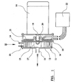
- FIGURE 1 is a sectional view through a water pump in accordance with this invention;
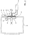
- FIGURE 2 is a sectional view through an embodiment of oven in accordance with this invention; and
- FIGURE 3 is a sectional view through an alternative embodiment of oven in accordance with this invention.
-
- Referring to Figure 1 of the drawings, there is shown a water pump comprising an
electric motor 10 having apump assembly 11 mounted to one end thereof. Theassembly 11 comprisescylindrical casing 12 and animpeller 13 rotatably mounted inside a chamber of thecasing 12. The casing comprises aradially projecting inlet 14 and anaxially extending outlet 15. - The
impeller 13 is a one piece formation of metal comprising acircular base 16 and a plurality of axially extendingvanes 17 each lying in plane which extends substantially radially of the impeller. In use, as theimpeller 13 is rotated, water is drawn from the outside of the impeller chamber, radially through itsvanes 17 and axially out through the central part of theimpeller 13. Ashaft 18 extends through therear casing wall 19 and is secured such that it can rotate freely by means of abearing 20. Preferably theshaft 18 is a poor thermal conductor so that heat does not substantially conduct into the rotational drive arrangement. - The
rear casing wall 19 lies parallel to thebase 16 of theimpeller 13. Therear casing wall 19 is made of a material which allows electromagnetic waves to pass through it, such as plastic or glass. On the other side of thecasing wall 19 and positioned around theshaft 18 is a substantiallyflat coil 21. - Preferably the
coil 21 is made from copper rope or braid and is of the Litz construction, whereby thecoil 21 is multi-stranded with each strand electrically insulated from each other. Thecoil 21 is positioned adjacent to thepump impeller 13 and forms part of the resonant tank circuit of a highfrequency power generator 22, which could be of the series resonant inverter type. When thecoil 21 is powered with high frequency current a high frequency magnetic field is produced. The magnetic lines of force in the magnetic field produce eddy currents in theimpeller support plate 16. These eddy currents flow in a circular path around each line of force in the metal and create heat in the metal due to its electrical resistance; hence thewhole pump impeller 13 heats up. - The water is pumped with high turbulence, which is important to achieve high heat transfer efficiency. This, in conjunction with the heat generated in the
pump impeller 13 by thecoil 21 and theinduction generator 22 provides a very efficient water heating apparatus. - Preferably there is a small space between the
coil 11 and thecasing wall 19, which is either naturally or force ventilated to keep thecoil 21 cool. The continual heating up and cooling down of thepump impeller 13 and its motion remove any scale build up on the pump impeller 13: This can be enhanced by coating theimpeller 13 with a non-stick surface such as PTFE. The continual expansion and contraction of thepump impeller 13, cracks the scale off its surface, which is then spun off by centrifugal force, hence maintaining a high heat transfer efficiency. - In use, when the
motor 10 is operating and theimpeller 13 is rotating in a direction which draws the water from theinlet 14 and delivers it to theoutlet 15, thehigh frequency generator 22 feeds theinduction coil 21 with high frequency current and thepump impeller 13 thus heats up. - Water at the
inlet 14 is drawn through thehot impeller vanes 17 and out through theoutlet 15. The water flows through thevanes 17 in a turbulent manner and therefor extracts heat from theimpeller 13 very efficiently. It is then pushed out of theoutlet 15. - If the unit is part of a re-circulating system then water will flow back into the inlet and through the impeller to pick up more heat. A
temperature sensor 23 placed in the outlet or inlet stream will detect the water temperature and can be used to control the water temperature by regulating the motor speed and/or the power supplied to theinduction coil 21. - In this manner a compact, energy efficient and cost effective water heating/re-circulating system can be produced.
- Referring to Figure 2 of the drawings, there is shown an oven comprising a thermally insulated
housing 24 having anaperture 25, over which is positioned aplate 26 formed of a non-metallic and thermally insulating material. Protruding through theplate 26 is ashaft 27 secured such that it can rotate freely by means of abearing 28. Preferably theshaft 27 is a poor thermal conductor so that heat does not substantially conduct into the rotational drive arrangement. - Attached to the
shaft 27 is ametal fan impeller 29 of the radial flow or centrifugal type. Thebase 30 of theimpeller 29 lies substantially flat against thecover plate 26. On the other side of thecover plate 26 and positioned around theshaft 27 is a substantiallyflat coil 31. Preferably thecoil 31 is made from copper rope or braid and is of the Litz construction, whereby thecoil 31 is multi-stranded with each strand electrically insulated from each other. Thecoil 31 is positioned adjacent to thefan impeller 29 and forms part of the resonant tank circuit of a highfrequency power generator 32, which could be of the series resonant inverter type. - When the
coil 31 is powered with high frequency current a high frequency magnetic field is produced. The magnetic lines of force in the magnetic field produce eddy currents in thebase 30 of thefan impeller 29. These eddy currents flow in a circular path around each line of force in the metal and create heat in the metal due to its electrical resistance: hence thewhole fan impeller 29 heats up. - Means (not shown) are provided to rotate the
fan impeller 29 in a way that air inside the oven cavity is drawn into the centre of thecentrifugal fan impeller 29 and then blown out at its periphery, hence circulating the air in the oven. This in conjunction with the heat generated in thefan impeller 29 by thecoil 31 and theinduction generator 32 provides a very efficient convected air heating system. - Preferably there is a small space 33 between the
coil 31 and thecover plate 26, which is either naturally or force ventilated to keep thecoil 31 cool. Projecting through the wall of the cavity is apipe 34, one end of which points into thefan impeller 29. The other end of thepipe 34 is attached to avalve 35 which when actuated allows water to pass from awater tank 36 to thepipe 34. The water is then delivered via thepipe 34 onto thehot fan impeller 29 where it is converted into steam; this steam is then dispersed throughout the oven by thefan impeller 29. - The fact that the water is converted to steam on the
fan impeller 29 makes it resistant to scaling problems. Scale builds up on thefan impeller 29, which is removed by the continual heating up and cooling down of thefan impeller 29. This continual expansion and contraction of thefan impeller 29, cracks the scale off the surface of thefan impeller 29, which is then spun off by centrifugal force and finally removed by normal oven cleaning. - It is relatively straightforward for those skilled in the art to provide control systems, which controls oven temperature, humidity and timing sequences to provide combinations of convected hot air and/or steam.
- In a second embodiment of the invention, shown in Figure 3, an
oven cavity 38 identical to the one described in the first embodiment is provided with a different fan impeller and coil arrangement. Preferably thefan impeller 39 is again of the metal centrifugal-flow type, and is fitted around its periphery is anannular metal ring 40. Preferably themetal ring 40 is thermally insulated from thefan impeller 39 byinsulation spacers 41 so that when thering 40 is heated, very little heat conducts back to thefan impeller 39. - Positioned at the edge of the
ring 40 is atrough 42 suitable for carrying water. Thetrough 42 is positioned so that the edge of thering 40 is inside thetrough 42 and when thefan impeller 39 andring 40 are rotated, the edge of thering 40 revolves in thetrough 42. On the other side of thecover plate 43 and positioned around theshaft 44 are two substantiallyflat coils coils Coil 45 is a flat circular coil positioned adjacent to thefan impeller 39 andcoil 35 is a flatannular coil 46 positioned adjacent to thering 40. The twocopper coils frequency power generators - As described in the first embodiment, when high frequency current passes through the
coils cover plate 43 and into the rear metal faces of thefan impeller 39 and themetal ring 40, thereby heating them up. As thecoils frequency power generators fan impeller 39 and in thering 40 can be adjusted independently of each other. - Fitted to the
trough 42 is apipe 49, which protrudes through the wall of the oven cavity, and supplies thetrough 42 with water. Means are provided to rotate thefan impeller 39 andring 40 in a way that air inside the oven cavity is drawn into the centre of thecentrifugal fan impeller 39 and blown out at its periphery hence circulating the air in the oven. This in conjunction with the heat generated in thefan impeller 39 by thecoil 45 and theinduction generator 47 provides a very efficient convected air heating system. - Preferably there is a small space between the
coils cover plate 43 which is either naturally or force ventilated to keep thecoils ring 40 viacoil 46 and rotating thehot ring 40 in thetrough 42, which contains water supplied throughpipe 49 generates steam. This arrangement is not susceptible to water scaling problems due to the continual heating and cooling of themetal ring 40 which sheds the accumulated scale as thering 40 expands and contracts. - It is relatively easy for those skilled in the art to design control systems which control oven temperature, humidity and timing sequences to provide convected hot air and/steam.
- In a third embodiment (not shown). A system is provided the same as that disclosed above, except that spraying or dropping the water onto the
hot metal ring 40 generates the steam. Projecting through the wall of the oven cavity is a pipe, the end of which points onto thehot metal ring 40. Attached to the other end of the pipe is a valve which when actuated allows water to flow from a water tank through the pipe and fall or spray onto thehot metal ring 40. In this manner steam is produced and is distributed around the oven via the re-circulating centrifugal fan impeller.
Claims (10)
- A fluid heating apparatus comprising a flow duct for the fluid to be heated, an electrically inductive impeller disposed in the flow duct, drive means arranged to rotate the impeller to cause the fluid to flow along the flow duct and a coil disposed adjacent the impeller and arranged to induce eddy currents therein.
- A fluid heating apparatus as claimed in claim 1, in which the impeller is formed of metal.
- A fluid heating apparatus as claimed in claims 1 or 2, in which the coil is disposed outside the flow duct on the opposite side of a wall thereof to the impeller.
- A fluid heating apparatus as claimed in claim 3, in which the wall is formed of a magnetically permeable material.
- A fluid heating apparatus as claimed in any preceding claim, in which the impeller is arranged to cause the fluid to flow radially of the axis of rotation of the impeller.
- A fluid heating apparatus as claimed in claim 5, in which the impeller comprises a base lying normal to the axis of rotation and plurality of axially extending vanes.
- A fluid heating apparatus as claimed in claim 6, in which the base of the impeller is mounted adjacent a flat portion of the wall of the flow duct, the coil being disposed on the opposite side of said flat wall portion
- A fluid heating apparatus as claimed in any preceding claim, in which the coil is flat.
- A fluid heating apparatus as claimed in claim 8, in which the flat coil lies in a plane normal to the axis of rotation of the impeller.
- A fluid heating apparatus as claimed in any preceding claim, in which means are provided for directing steam or water onto the impeller.
Applications Claiming Priority (2)
| Application Number | Priority Date | Filing Date | Title |
|---|---|---|---|
| GB0003802A GB2362306A (en) | 2000-02-19 | 2000-02-19 | Eddy current heating of fluid flow impeller |
| GB0003802 | 2000-02-19 |
Publications (2)
| Publication Number | Publication Date |
|---|---|
| EP1130336A2 true EP1130336A2 (en) | 2001-09-05 |
| EP1130336A3 EP1130336A3 (en) | 2003-04-02 |
Family
ID=9885904
Family Applications (1)
| Application Number | Title | Priority Date | Filing Date |
|---|---|---|---|
| EP01301253A Withdrawn EP1130336A3 (en) | 2000-02-19 | 2001-02-14 | High efficiency fluid heating apparatus |
Country Status (2)
| Country | Link |
|---|---|
| EP (1) | EP1130336A3 (en) |
| GB (1) | GB2362306A (en) |
Cited By (7)
| Publication number | Priority date | Publication date | Assignee | Title |
|---|---|---|---|---|
| FR2943766A1 (en) * | 2009-03-31 | 2010-10-01 | R E M | GROUP FOR RAPID PRODUCTION OF HOT WATER OR STEAM. |
| CN103267346A (en) * | 2013-06-03 | 2013-08-28 | 吴泽松 | Water heater with elevator brake resistor |
| WO2016071118A1 (en) * | 2014-11-06 | 2016-05-12 | Xylem Ip Management S.À R.L. | Temperature control apparatus |
| GB2543704A (en) * | 2016-02-10 | 2017-04-26 | Rotaheat Ltd | Heat generator |
| ES2673743A1 (en) * | 2016-12-23 | 2018-06-25 | Bsh Electrodomésticos España, S.A. | INDUCTION COOKING DEVICE DEVICE WITH ONE UNIT OF FAN AND COOKING APPARATUS WITH SAID DEVICE (Machine-translation by Google Translate, not legally binding) |
| US10425998B2 (en) | 2013-08-22 | 2019-09-24 | Rotaheat Limited | Heat generator |
| DE102020216534A1 (en) | 2020-12-23 | 2022-06-23 | Wilhelm Bruckbauer | cooking appliance |
Citations (5)
| Publication number | Priority date | Publication date | Assignee | Title |
|---|---|---|---|---|
| JPH06123486A (en) * | 1992-10-08 | 1994-05-06 | Heiwa Shoji Kk | Induction water heater |
| US5914065A (en) * | 1996-03-18 | 1999-06-22 | Alavi; Kamal | Apparatus and method for heating a fluid by induction heating |
| DE19908443A1 (en) * | 1998-02-26 | 1999-09-02 | Japan Res & Dev Ass | Combination microwave and induction heating cooker |
| DE19915842A1 (en) * | 1998-04-09 | 1999-12-23 | Usui Kokusai Sangyo Kk | Magnetic heater |
| DE19922223A1 (en) * | 1998-05-19 | 1999-12-23 | Usui Kokusai Sangyo Kk | Heating and forced feeding device for liquids |
Family Cites Families (5)
| Publication number | Priority date | Publication date | Assignee | Title |
|---|---|---|---|---|
| US4421967A (en) * | 1980-07-21 | 1983-12-20 | Vs Systems, Inc. | Windmill driven eddy current heater |
| SU1166346A1 (en) * | 1982-02-18 | 1985-07-07 | Adamenko Aleksej | Device for induction heating of liquid |
| DE3216404C2 (en) * | 1982-05-03 | 1984-05-03 | Arthur Pfeiffer Vakuumtechnik Wetzlar Gmbh, 6334 Asslar | Heating for a turbo molecular pump |
| GB2262693B (en) * | 1991-12-17 | 1995-06-07 | Electricity Ass Tech | Induction heater |
| JP3148699B2 (en) * | 1997-09-30 | 2001-03-19 | 食品産業電子利用技術研究組合 | Cooking device |
-
2000
- 2000-02-19 GB GB0003802A patent/GB2362306A/en not_active Withdrawn
-
2001
- 2001-02-14 EP EP01301253A patent/EP1130336A3/en not_active Withdrawn
Patent Citations (5)
| Publication number | Priority date | Publication date | Assignee | Title |
|---|---|---|---|---|
| JPH06123486A (en) * | 1992-10-08 | 1994-05-06 | Heiwa Shoji Kk | Induction water heater |
| US5914065A (en) * | 1996-03-18 | 1999-06-22 | Alavi; Kamal | Apparatus and method for heating a fluid by induction heating |
| DE19908443A1 (en) * | 1998-02-26 | 1999-09-02 | Japan Res & Dev Ass | Combination microwave and induction heating cooker |
| DE19915842A1 (en) * | 1998-04-09 | 1999-12-23 | Usui Kokusai Sangyo Kk | Magnetic heater |
| DE19922223A1 (en) * | 1998-05-19 | 1999-12-23 | Usui Kokusai Sangyo Kk | Heating and forced feeding device for liquids |
Non-Patent Citations (1)
| Title |
|---|
| PATENT ABSTRACTS OF JAPAN vol. 018, no. 418 (M-1650), 5 August 1994 (1994-08-05) & JP 06 123486 A (HEIWA SHOJI KK), 6 May 1994 (1994-05-06) * |
Cited By (13)
| Publication number | Priority date | Publication date | Assignee | Title |
|---|---|---|---|---|
| EP2239523A2 (en) | 2009-03-31 | 2010-10-13 | R.E.M. | Quick heating device for water or vapour |
| FR2943766A1 (en) * | 2009-03-31 | 2010-10-01 | R E M | GROUP FOR RAPID PRODUCTION OF HOT WATER OR STEAM. |
| CN103267346A (en) * | 2013-06-03 | 2013-08-28 | 吴泽松 | Water heater with elevator brake resistor |
| US10425998B2 (en) | 2013-08-22 | 2019-09-24 | Rotaheat Limited | Heat generator |
| US10533149B2 (en) | 2014-11-06 | 2020-01-14 | Xylem Ip Management S.À R.L. | Temperature control apparatus |
| WO2016071118A1 (en) * | 2014-11-06 | 2016-05-12 | Xylem Ip Management S.À R.L. | Temperature control apparatus |
| GB2543704B (en) * | 2016-02-10 | 2018-06-06 | Rotaheat Ltd | Heat generator |
| GB2543704A (en) * | 2016-02-10 | 2017-04-26 | Rotaheat Ltd | Heat generator |
| US10912157B2 (en) | 2016-02-10 | 2021-02-02 | Rotaheat Limited | Heat generator |
| ES2673743A1 (en) * | 2016-12-23 | 2018-06-25 | Bsh Electrodomésticos España, S.A. | INDUCTION COOKING DEVICE DEVICE WITH ONE UNIT OF FAN AND COOKING APPARATUS WITH SAID DEVICE (Machine-translation by Google Translate, not legally binding) |
| WO2018116059A1 (en) * | 2016-12-23 | 2018-06-28 | BSH Hausgeräte GmbH | Cooking appliance |
| US11530875B2 (en) | 2016-12-23 | 2022-12-20 | BSH Hausgeräte GmbH | Cooking appliance |
| DE102020216534A1 (en) | 2020-12-23 | 2022-06-23 | Wilhelm Bruckbauer | cooking appliance |
Also Published As
| Publication number | Publication date |
|---|---|
| GB0003802D0 (en) | 2000-04-05 |
| EP1130336A3 (en) | 2003-04-02 |
| GB2362306A (en) | 2001-11-14 |
Similar Documents
| Publication | Publication Date | Title |
|---|---|---|
| US6011245A (en) | Permanent magnet eddy current heat generator | |
| KR101489025B1 (en) | Electromagnetic induction type heating device, hot-blast generating device, and power generating device | |
| WO2016138475A1 (en) | Magnetic induction heat engine and heat pipe delivery system and methods of producing and delivering heat | |
| CN101292806A (en) | Electromagnetic induction heating type electric hair drier | |
| KR20070081242A (en) | Induction heating element for heater and heater thereof | |
| EP1130336A2 (en) | High efficiency fluid heating apparatus | |
| US6504136B2 (en) | Liquid heating apparatus with an inductively heated impeller | |
| KR101812720B1 (en) | Heater using magnets | |
| JP2897083B2 (en) | Hot air heater | |
| CN105737126A (en) | Instant superheated steam generator with quartz tube | |
| CN209101368U (en) | A kind of cleaning apparatus for self of kitchen ventilator | |
| RU2303861C2 (en) | Device for heating liquid | |
| KR20110103637A (en) | Induction heating device using magnetic | |
| CN106813394A (en) | Intelligent electromagnetic air heater | |
| CN208301551U (en) | Air-channel heat-dissipation structure, host and food cooking machine | |
| JP5720937B2 (en) | Hot air generator using permanent magnets. | |
| JP5527685B2 (en) | Electromagnetic induction hot air generator and power generator | |
| KR20080103884A (en) | Device for moving liquid and method thereof | |
| RU73454U1 (en) | HEAT FAN WITH HEAT VENT | |
| CN105115018A (en) | Warm air blower | |
| JP3121787B2 (en) | Cooking device | |
| JPH094806A (en) | Heating device | |
| EP2405144A2 (en) | Radial fan | |
| CN208566772U (en) | A kind of electric-controlled plate of electromagnetic oven | |
| US20170276404A1 (en) | Faraday Effect Circulating Heat System and Method |
Legal Events
| Date | Code | Title | Description |
|---|---|---|---|
| PUAI | Public reference made under article 153(3) epc to a published international application that has entered the european phase |
Free format text: ORIGINAL CODE: 0009012 |
|
| AK | Designated contracting states |
Kind code of ref document: A2 Designated state(s): AT BE CH CY DE DK ES FI FR GB GR IE IT LI LU MC NL PT SE TR |
|
| AX | Request for extension of the european patent |
Free format text: AL;LT;LV;MK;RO;SI |
|
| PUAL | Search report despatched |
Free format text: ORIGINAL CODE: 0009013 |
|
| AK | Designated contracting states |
Kind code of ref document: A3 Designated state(s): AT BE CH CY DE DK ES FI FR GB GR IE IT LI LU MC NL PT SE TR Designated state(s): AT BE CH CY DE DK ES FI FR GB GR IE IT LI LU MC NL PT SE TR |
|
| AX | Request for extension of the european patent |
Extension state: AL LT LV MK RO SI |
|
| RIC1 | Information provided on ipc code assigned before grant |
Ipc: 7H 05B 6/02 B Ipc: 7F 24H 1/22 A |
|
| 17P | Request for examination filed |
Effective date: 20031006 |
|
| AKX | Designation fees paid |
Designated state(s): AT BE CH CY DE DK ES FI FR GB GR IE IT LI LU MC NL PT SE TR |
|
| 17Q | First examination report despatched |
Effective date: 20041221 |
|
| STAA | Information on the status of an ep patent application or granted ep patent |
Free format text: STATUS: THE APPLICATION IS DEEMED TO BE WITHDRAWN |
|
| 18D | Application deemed to be withdrawn |
Effective date: 20050503 |