EP1125077B1 - Method and apparatus for controlling a shape memory alloy fuel injector - Google Patents
Method and apparatus for controlling a shape memory alloy fuel injector Download PDFInfo
- Publication number
- EP1125077B1 EP1125077B1 EP99956656A EP99956656A EP1125077B1 EP 1125077 B1 EP1125077 B1 EP 1125077B1 EP 99956656 A EP99956656 A EP 99956656A EP 99956656 A EP99956656 A EP 99956656A EP 1125077 B1 EP1125077 B1 EP 1125077B1
- Authority
- EP
- European Patent Office
- Prior art keywords
- sma element
- state
- voltage
- valve
- sma
- Prior art date
- Legal status (The legal status is an assumption and is not a legal conclusion. Google has not performed a legal analysis and makes no representation as to the accuracy of the status listed.)
- Expired - Lifetime
Links
Images


Classifications
-
- F—MECHANICAL ENGINEERING; LIGHTING; HEATING; WEAPONS; BLASTING
- F16—ENGINEERING ELEMENTS AND UNITS; GENERAL MEASURES FOR PRODUCING AND MAINTAINING EFFECTIVE FUNCTIONING OF MACHINES OR INSTALLATIONS; THERMAL INSULATION IN GENERAL
- F16K—VALVES; TAPS; COCKS; ACTUATING-FLOATS; DEVICES FOR VENTING OR AERATING
- F16K31/00—Actuating devices; Operating means; Releasing devices
- F16K31/02—Actuating devices; Operating means; Releasing devices electric; magnetic
- F16K31/025—Actuating devices; Operating means; Releasing devices electric; magnetic actuated by thermo-electric means
-
- Y—GENERAL TAGGING OF NEW TECHNOLOGICAL DEVELOPMENTS; GENERAL TAGGING OF CROSS-SECTIONAL TECHNOLOGIES SPANNING OVER SEVERAL SECTIONS OF THE IPC; TECHNICAL SUBJECTS COVERED BY FORMER USPC CROSS-REFERENCE ART COLLECTIONS [XRACs] AND DIGESTS
- Y10—TECHNICAL SUBJECTS COVERED BY FORMER USPC
- Y10T—TECHNICAL SUBJECTS COVERED BY FORMER US CLASSIFICATION
- Y10T137/00—Fluid handling
- Y10T137/0318—Processes
Definitions
- This invention relates to the control of a fuel injector incorporating a shape memory alloy actuator element, and more particularly to a method and apparatus for maximizing performance of the injector while minimizing variability.
- Shape memory alloy (SMA) elements exhibit a temperature related shape transformation corresponding to an inherent bi-stable crystalline structure. This characteristic has been used to advantage in various control devices, with the temperature of the SMA element being controlled by electric heating. For example, it has been proposed to use an SMA element to move an armature for opening and closing a fluid valve, such as described in the U.S. Patent No. 4,973,024, issued on November 27, 1990, and in the U.S. Patent No. 5,325,880, issued on July 5, 1994.
- the control of these and other SMA devices may be either open-loop (i.e., based on experimentally determined characteristics of the device) or closed-loop (i.e., based on a feedback signal related to the parameter being controlled). Additionally, or alternatively, the resistance of the SMA element can be monitored for feedback purposes, as mentioned in the above-referenced U.S. Patent No. 5,325,880, since the SMA material exhibits a characteristic change in resistivity during its shape transformation.
- the present invention is directed to an improved method and apparatus for opening and closing a high performance SMA fuel injector, wherein performance variations due to changes in ambient temperature are minimized.
- a relatively high voltage is applied to an SMA element of the injector to quickly heat the element to its high temperature state, quickly opening the valve.
- the current level is monitored as a measure of the element resistivity, and when the determined resistivity indicates that the high temperature state transition is complete, the voltage is reduced to a hold value, sufficient to continue resistivity measurement.
- the high voltage is re-applied to begin a new control cycle.
- the electric heating is discontinued, and fuel circulating through the injector cools the element to its ambient temperature state.
- the variability in opening response is reduced because the high voltage is significantly higher than a voltage that would thermally damage the SMA element if sustained, and the resistivity feedback during application of the high voltage is used to control the timing of the current reduction.
- the variability in closing response is reduced by the repeated switching between high and low voltage control, which controls the temperature of the element, and thereby maintains the element in a state of readiness to return to the ambient temperature state. Additionally, the repeated switching between high and low voltage control limits the peak temperature of the SMA element, and prevents damage to the element if the circulating fuel fails to adequately cool the element, or in the event that no fuel is available to cool the SMA element. Finally, the use of current measurement in the control circuit permits reliable determination of the resistivity of the SMA element without requiring external thermal sensors.
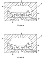
- the reference numeral 10 generally designates an actuator for an automotive fuel injector, including a valve 20 and a Shape Memory Alloy (SMA) element 22 in contact with valve 20.
- the SMA element 22 is supported on a metering plate 24 having an orifice 26 and a pair of outlet flow paths 28a, 28b disposed on either side of the orifice 26.
- the valve can be positioned upward as shown in Figure 1A to open the orifice 26, or downward as shown in Figure 1B to close the orifice 26.
- An annular recess 30 surrounding the orifice 26 receives a complementary portion of valve 20 when the actuator 10 is in the closed position of Figure 1B.
- a housing element 32 surrounding the metering plate 24 defines a fuel cavity 34, an inlet flow path 36, and an annular outlet flow path 38 coupled to the outlet flow paths 28a, 28b.
- the orifice 26 is coupled to the intake chamber of an internal combustion engine, and the outlet flow path 38 is coupled to a fuel reservoir. Fuel enters through inlet flow path 36 and fills the cavity 34. If valve 20 is open, a portion of the fuel passes through orifice 26, and the excess fuel is returned to the reservoir via outlet flow path 38.
- the system is designed so that there is a continuous flow of fuel across the SMA element 22 in either position of the valve 20. The circulating fuel flow quickly cools the SMA element 22 to the ambient temperature of the fuel in the reservoir.
- the actuator 10 is designed so that the valve 20 is biased to the closed position shown in Figure 1B when SMA element 22 is in an ambient temperature state at or below a first characteristic temperature (referred to as the martensite finish temperature Tmf).
- a first characteristic temperature referred to as the martensite finish temperature Tmf
- the austenite start temperature Tas When heated to a second characteristic temperature (referred to as the austenite start temperature Tas) by electric resistance heating, the SMA element 22 begins a crystalline phase change, which is completed when the SMA element reaches a third characteristic temperature (referred to as the austenite finish temperature Taf).
- the SMA element shrinks in length to move valve 20 to the open position depicted in Figure 1A.
- the SMA element 22 is heated by electric resistance heating to open the valve 20, and when the heating is terminated, the SMA element 22 is cooled by the flow of ambient temperature fuel through the cavity 34 to close the valve 20.
- the valve 20 is in the closed position at ambient fuel temperature, and in the open position when SMA element 22 is heated, it will be understood the actuator 10 could just as well be designed so that the valve 20 is open at ambient fuel temperature and closed when SMA element 22 is heated.
- an intermediate phase (referred to as the Rhombohedral-Phase or R-Phase) is encountered as the temperature of the material is increased and the crystalline structure begins to change phase.
- R-Phase an intermediate phase
- the martensite crystal structure initially changes to the R-Phase crystal structure followed by the austenite crystal structure.
- the R-Phase crystal structure may also be encountered when the material is subsequently cooled.
- Figure 2 shows the resistance of element 22 as a function of temperature, as the temperature is varied from the martensite finish temperature Tmf to the austenite finish temperature Taf.
- the relationship for increasing temperatures i.e., martensitic to austenitic
- the relationship for decreasing temperatures i.e., austenitic to martensitic
- the element 22 has an electrical resistance designated as Rmf.
- Rmf the electrical resistance
- the slope of the resistance vs. temperature curve changes due to the start of the crystalline phase change from martensite to austenite.
- the slope of the resistance vs. temperature curve again changes to reflect the pure austenitic phase resistivity.
- Increasing the temperature above the austenite finish temperature Taf results in further increases in resistivity due to the thermal coefficient of resistance of the austenite phase.
- maximum performance is achieved by quickly heating the element 22 at the start of the injection signal to quickly and fully open the valve 20, and quickly cooling the element 22 at the end of the injection signal to quickly and fully close the valve 20.
- Fast heating of the element 22 can be effected by passing a large current through it, but overheating must be avoided to prevent thermal damage to the element.
- overheating the element impairs the ability to quickly cool the element 22 for closing the valve 20. Consequently, the conventional approaches to heating and cooling SMA elements involve significant trade-offs that sacrifice the performance of the controlled device.
- This invention overcomes the above-described problems by controlling the injector 10 such that the element 22 is quickly heated with high power at the start of the injection enable signal, and the heating is modulated once the injector has opened to maintain the temperature of the element 22 at some predetermined level above the austenitic finish temperature Taf.
- the modulation permits the use of high power to quickly open the injector 10, while preventing overheating of the element 22, and thereafter maintains the element 22 in a state of readiness to be cooled by the circulating fuel at the end of the injection signal.
- the only factors affecting the performance of the injector and the variability in opening and closing are environmental in nature - i.e., the temperature of the fuel.
- the variability associated with different fuel temperatures can be significantly reduced by varying the holding temperature of the SMA element in accordance with the fuel temperature. This can be accomplished either with discrete circuitry providing temperature feedback, or with a microprocessor-based controller through the use of a look-up table based on fuel temperature or a related parameter developed for other engine controls.
- FIG. 3 depicts the SMA element 22 and an injector driver circuit 40 for controlling the heating of SMA element 22 in an automotive environment.
- An automotive storage battery B is coupled to terminal 42 of driver circuit 40 via ignition switch IS.
- the driver circuit includes a power FET Q1, a bias FET Q2, the bridge resistors R1-R3 and the bias resistors R4-R5.
- One end of element 22 is connected to terminal 42, and the other end is connected to ground (the negative terminal of battery B) via bridge resistor R3 and the drain-source circuit of power FET Q1.
- An injection enable signal EN is coupled to the gate of power FET Q1 via bias resistor R4.
- the serially coupled bridge resistors R1 and R2 are connected in parallel with the series combination of element 22 and bridge resistor R3, defining a reference voltage at junction J1.
- the reference voltage at the junction J1 is applied to the non-inverting input of comparator 120, and the voltage at a junction J2 between element 22 and bridge resistor R3 is applied to the inverting input of comparator 120.
- the output of comparator 120 operates bias FET Q2, which couples the bias resistor R4 to ground through bias resistor R5 and its own drain-source circuit.
- the power transistor Q1 When the injector signal transitions from a logic zero to a logic one, the power transistor Q1 is biased to a fully conductive state through bias resistor R4, sourcing maximum current from battery B through element 22 and bridge resistor R3.
- Bridge resistor R3 serves as a shunt resistor, and has a value of about 100m ⁇ , for example.
- the voltage at junction J2 decreases as the resistance of element 22 increases during its transition from martensitic to austenitic crystalline structure, described above.
- the comparator 120 When the voltage at junction J2 falls below a reference voltage (at junction J1) the comparator 120 switches to a low impedance output state, sourcing current from the gate of bias transistor Q2 to bias transistor Q2 conductive.
- the bridge resistors R1 and R2 are chosen so that the comparator 120 switches when the resistance of element 22 reaches its specified resistance value Rc. This is achieved by selecting a suitable value of resistor R2, and setting resistor R1 according to the expression: (Raf)(R2)/R3.
- the bias transistor Q2 lowers the bias voltage of power transistor Q1 through bias resistor R5. This switches power transistor Q1 to a low current state in which the current sourced through element 22 is reduced to a relatively low level, such as 100 mA, that permits partial cooling of the element 22 by the circulating fuel.
- a relatively low level such as 100 mA
- the comparator 120 continues to switch in this manner so long as the injection signal remains at a logic one level, thereby limiting the peak temperature of element 22 to the control temperature Tc.
- the switching rate during such operation is determined as a function of fuel temperature (cooling rate) and the hysteresis of comparator 120.
- FIG. 4 Graphs A-D, graphically depict an injection cycle of actuator 10 according to this invention.
- Graph A depicts a logic level injection signal
- Graph B depicts the temperature of element 22
- Graph C depicts the resistance of element 22
- Graph D depicts the length of the element 22.
- Multiple traces are shown in Graphs B-D to illustrate the variability associated with three different fuel temperatures: 35°C (solid traces), 20°C (dashed traces), and -40°C (dash-dot traces). It is seen that the high apply voltage causes a quick increase in element temperature, minimizing valve opening variability, even at very cold fuel temperatures. At warmer fuel temperatures, the cycling of transistor Q1 between its high and low current states controls the temperature of the element 22 so that is can be quickly cooled to close the valve when the transistor Q1 is turned off.
- the above described control enables high performance operation of a SMA fuel injector.
- the element may be quickly heated without thermal damage to quickly open the injector, and maintained in a state of thermal readiness so that the injector can be quickly and consistently cooled at the end of the injection period.
Landscapes
- Engineering & Computer Science (AREA)
- General Engineering & Computer Science (AREA)
- Mechanical Engineering (AREA)
- Fuel-Injection Apparatus (AREA)
Description
Claims (11)
- A control method for activating an actuator having a SMA element that assumes a deactivated state at ambient temperature and an activated state at an elevated temperature, the control method comprising the steps of:when activation of said actuator is desired:(a) applying a high voltage to the SMA element to initiate a transition from said deactivated state to said activated state, and monitoring a current through said element during the application of said high voltage;(b) when the monitored current reaches a first threshold corresponding to a resistivity of said SMA element that occurs when said SMA element has attained said activated state, lowering the voltage applied to said SMA element, and monitoring the current through the element during application of said lowered voltage; and(c) when the monitored current during the application of said lowered voltage reaches a second threshold corresponding to a resistivity of said SMA element that occurs prior to an onset of transition to said deactivated state, re-applying said high voltage and cyclically lowering said applied voltage in accordance with steps (b) and (c), so as to maintain the SMA element in a state of readiness to return to said deactivated state; andwhen deactivation of said actuator is desired, removing said applied voltage, and cooling said SMA element, so as to return said SMA element to said deactivated state.
- The control method of Claim 1, wherein said high voltage is higher than a voltage that would thermally damage said SMA element if sustained, thereby to quickly open said actuator.
- The control method of Claim 1, wherein the cyclic lowering of the applied voltage limits a peak temperature of said SMA element.
- A control method for opening and closing a fluid valve having a SMA element that positions a valve element to a closed position when said SMA element is in an ambient temperature state and an open position when said SMA element is an elevated temperature state, the control method comprising the steps of:when valve opening is desired:(a) applying a high voltage to the SMA element to initiate movement of said valve element toward said open position, and monitoring a current through said element during the application of said high voltage;(b) when the monitored current reaches a first threshold corresponding to a resistivity of said SMA element that occurs when said SMA element has attained said elevated temperature state, lowering the voltage applied to said SMA element, and monitoring the current through the element during application of said lowered voltage; and(c) when the monitored current during the application of said low voltage reaches a second threshold corresponding to a resistivity of said SMA element that occurs prior to an onset of transition to said ambient temperature state, cyclically applying said high voltage and lowering said applied voltage in accordance with steps (b) and (c), so as to maintain the SMA element in a state of readiness to return to said ambient temperature state; andwhen valve closing is desired, removing said applied voltage, and cooling said SMA element, so as to return said SMA element to its ambient temperature state.
- The control method of Claim 4, wherein said high voltage is higher than a voltage that would thermally damage said SMA element if sustained, thereby to quickly open said valve.
- The control method of Claim 4, wherein the cyclic application of the high voltage and lowering of the applied voltage limits a peak temperature of said SMA element.
- The control method of Claim 4, wherein the cooling of said SMA element is achieved by a fluid controlled by said valve.
- The control method of Claim 7, wherein said first and second thresholds are adjusted based on a temperature of said controlled fluid so as to minimize temperature related variability in closing of said valve.
- Control apparatus for opening and closing a valve having a SMA element (22) that moves a valve element to a deactivated position when said SMA element is in an ambient temperature state and an activated position when said SMA element is in an elevated temperature state, the control apparatus comprising:a voltage source (B);a power transistor (Q1) coupling said voltage source to said SMA element;a bias circuit (R4, R5, Q2) for biasing said power transistor to a conductive state to establish current flow through said SMA element while valve activation is commanded, the bias circuit being operative in a first state in which said power transistor applies a maximum voltage of said source across said SMA element, and a second state in which said power transistor applies a minimum voltage of said source across said SMA element; anda comparator (120) connected to monitor current through said SMA element during the commanded open period of said valve for switching the bias circuit from said first state to said second state when the monitored current reaches a first threshold corresponding to a resistivity of said SMA element that occurs when said SMA element attains said elevated temperature state, and switching the bias circuit from said second state to said first state when the monitored current reaches a second threshold corresponding to a resistivity of said SMA element that occurs prior to an onset of transition to said ambient temperature state.
- A control apparatus as set forth in Claim 9, wherein said second threshold is determined by a characteristic hysteresis of said comparator.
- The control apparatus of Claim 9, wherein said maximum voltage is higher than a voltage that would thermally damage said SMA element if sustained, thereby to quickly move said valve element to said activated position when valve activation is commanded.
Applications Claiming Priority (3)
| Application Number | Priority Date | Filing Date | Title |
|---|---|---|---|
| US178958 | 1980-08-18 | ||
| US09/178,958 US6019113A (en) | 1998-10-26 | 1998-10-26 | Method and apparatus for controlling a shape memory alloy fuel injector |
| PCT/US1999/024951 WO2000025053A1 (en) | 1998-10-26 | 1999-10-26 | Method and apparatus for controlling a shape memory alloy fuel injector |
Publications (2)
| Publication Number | Publication Date |
|---|---|
| EP1125077A1 EP1125077A1 (en) | 2001-08-22 |
| EP1125077B1 true EP1125077B1 (en) | 2004-12-01 |
Family
ID=22654619
Family Applications (1)
| Application Number | Title | Priority Date | Filing Date |
|---|---|---|---|
| EP99956656A Expired - Lifetime EP1125077B1 (en) | 1998-10-26 | 1999-10-26 | Method and apparatus for controlling a shape memory alloy fuel injector |
Country Status (4)
| Country | Link |
|---|---|
| US (1) | US6019113A (en) |
| EP (1) | EP1125077B1 (en) |
| DE (1) | DE69922402T2 (en) |
| WO (1) | WO2000025053A1 (en) |
Cited By (1)
| Publication number | Priority date | Publication date | Assignee | Title |
|---|---|---|---|---|
| DE102020114529B4 (en) | 2020-05-29 | 2022-03-31 | Alfmeier Präzision SE | Circuit arrangement for activating a system for a seat comfort function, method for activating a circuit arrangement and seat with a seat comfort system |
Families Citing this family (27)
| Publication number | Priority date | Publication date | Assignee | Title |
|---|---|---|---|---|
| NZ516970A (en) * | 1999-08-12 | 2004-01-30 | Nano Muscle Inc | Shape-memory alloy actuators and control methods |
| US6318641B1 (en) * | 2000-02-11 | 2001-11-20 | Delphi Technologies, Inc. | Shape memory alloy fuel injector small package integral design |
| US7075209B2 (en) * | 2000-07-18 | 2006-07-11 | Brigham Young University | Compliant bistable micromechanism |
| DE10056039A1 (en) * | 2000-11-11 | 2002-05-16 | Bosch Gmbh Robert | Fuel injection valve, for an IC motor, has a disk at the injection openings with a bi-metal or shape memory alloy section which is distorted by a heater to free selected injection openings with the same sealed seat |
| ATE392551T1 (en) | 2001-02-22 | 2008-05-15 | Alfmeier Praez Ag | MEMORY METAL ACTUATOR WITH IMPROVED TEMPERATURE CONTROL |
| US6691977B2 (en) | 2001-03-16 | 2004-02-17 | Delphi Technologies, Inc. | Shape memory alloy fuel injector |
| US6543224B1 (en) * | 2002-01-29 | 2003-04-08 | United Technologies Corporation | System and method for controlling shape memory alloy actuators |
| KR20040106494A (en) * | 2002-05-06 | 2004-12-17 | 나노머슬, 인크. | Actuator for two angular degrees of freedom |
| AU2003234522A1 (en) | 2002-05-06 | 2003-11-17 | Nanomuscle, Inc. | Reusable shape memory alloy activated latch |
| US8127543B2 (en) * | 2002-05-06 | 2012-03-06 | Alfmeier Prazision Ag Baugruppen Und Systemlosungen | Methods of manufacturing highly integrated SMA actuators |
| AU2003267114A1 (en) * | 2002-05-06 | 2003-11-11 | Nanomuscle, Inc. | High stroke, highly integrated sma actuators |
| EP1625317A4 (en) | 2003-04-28 | 2006-08-02 | Alfmeier Praez Ag | Flow control assemblies having integrally formed shape memory alloy actuators |
| KR20060041164A (en) * | 2003-05-02 | 2006-05-11 | 알프마이어 프레치지온 악티엔게젤샤프트 바우그룹펜 운트 지스템뢰중엔 | Gauge pointer with integrated shape memory alloy actuator |
| WO2005026592A2 (en) * | 2003-09-05 | 2005-03-24 | Alfmeier Präzision AG Baugruppen und Systemlösungen | A system, method and apparatus for reducing frictional forces and for compensating shape memory alloy-actuated valves and valve systems at high temperatures |
| JP2005090233A (en) * | 2003-09-12 | 2005-04-07 | Hitachi Unisia Automotive Ltd | Fuel injection valve |
| TW200700564A (en) * | 2005-04-04 | 2007-01-01 | Telezygology Inc | Smart memory alloy control |
| US7692091B2 (en) * | 2005-09-27 | 2010-04-06 | Karim Altaii | Shape memory alloy motor as incorporated into solar tracking mechanism |
| US7953319B2 (en) * | 2007-04-04 | 2011-05-31 | Konica Minolta Opto, Inc. | Position controller, driving mechanism and image pickup system |
| WO2009103252A2 (en) * | 2008-02-21 | 2009-08-27 | Coda Development, S.R.O. | A device for adjustment of pressure in tires. |
| US9057451B2 (en) * | 2009-06-11 | 2015-06-16 | Fluid Automation Systems Sa | Method and apparatus for actuating a valve |
| US8714199B2 (en) * | 2009-06-11 | 2014-05-06 | Fluid Automation Systems Sa | Method and apparatus for actuating a valve |
| US8584456B1 (en) | 2010-05-21 | 2013-11-19 | Hrl Laboratories, Llc | Bistable actuator mechanism |
| US8733097B2 (en) * | 2011-03-16 | 2014-05-27 | GM Global Technology Operations LLC | Multi-stage actuation for an active materials-based actuator |
| CZ2011757A3 (en) | 2011-11-22 | 2013-05-29 | Sithold S.R.O | Device for maintaining and change in pressure in pneumatic tire |
| CN104363821B (en) * | 2012-06-13 | 2017-03-08 | 皇家飞利浦有限公司 | Automatically non magnetic medical monitor using shape memory actuator |
| US9181933B2 (en) * | 2012-12-10 | 2015-11-10 | Alcatel Lucent | Temperature control device with a passive thermal feedback control valve |
| DE102013204725A1 (en) * | 2013-03-12 | 2014-09-18 | Robert Bosch Gmbh | Method for operating an electric fuel pump |
Family Cites Families (13)
| Publication number | Priority date | Publication date | Assignee | Title |
|---|---|---|---|---|
| US3229956A (en) * | 1962-03-02 | 1966-01-18 | Stevens Mfg Co Inc | Diaphragm fluid valve |
| CH418759A (en) * | 1964-12-23 | 1966-08-15 | Taco Heizungen Ag | Remote controlled valve for heating systems |
| US3613732A (en) * | 1969-07-17 | 1971-10-19 | Robertshaw Controls Co | Temperature-responsive valve operators |
| US3974844A (en) * | 1973-06-11 | 1976-08-17 | Texas Instruments Incorporated | Valve |
| US4551974A (en) * | 1984-04-27 | 1985-11-12 | Raychem Corporation | Shape memory effect actuator and methods of assembling and operating therefor |
| JPH0139909Y2 (en) * | 1984-11-07 | 1989-11-30 | ||
| JPS61136617A (en) * | 1984-12-06 | 1986-06-24 | Tokieda Naomitsu | Electrical conduction heating method of shape memory alloy |
| JPH0630016B2 (en) * | 1985-03-29 | 1994-04-20 | 株式会社日立製作所 | Position control device |
| US4973024A (en) * | 1989-09-26 | 1990-11-27 | Toki Corporation Kabushiki Kaisha | Valve driven by shape memory alloy |
| US5211371A (en) * | 1991-07-22 | 1993-05-18 | Advanced Control Technologies, Inc. | Linearly actuated valve |
| US5460010A (en) * | 1993-02-23 | 1995-10-24 | Sanyo Electric Co., Ltd. | Refrigerator |
| US5325880A (en) * | 1993-04-19 | 1994-07-05 | Tini Alloy Company | Shape memory alloy film actuated microvalve |
| US5619177A (en) * | 1995-01-27 | 1997-04-08 | Mjb Company | Shape memory alloy microactuator having an electrostatic force and heating means |
-
1998
- 1998-10-26 US US09/178,958 patent/US6019113A/en not_active Expired - Fee Related
-
1999
- 1999-10-26 WO PCT/US1999/024951 patent/WO2000025053A1/en active IP Right Grant
- 1999-10-26 EP EP99956656A patent/EP1125077B1/en not_active Expired - Lifetime
- 1999-10-26 DE DE1999622402 patent/DE69922402T2/en not_active Expired - Fee Related
Cited By (1)
| Publication number | Priority date | Publication date | Assignee | Title |
|---|---|---|---|---|
| DE102020114529B4 (en) | 2020-05-29 | 2022-03-31 | Alfmeier Präzision SE | Circuit arrangement for activating a system for a seat comfort function, method for activating a circuit arrangement and seat with a seat comfort system |
Also Published As
| Publication number | Publication date |
|---|---|
| US6019113A (en) | 2000-02-01 |
| DE69922402T2 (en) | 2005-05-19 |
| EP1125077A1 (en) | 2001-08-22 |
| DE69922402D1 (en) | 2005-01-05 |
| WO2000025053A1 (en) | 2000-05-04 |
Similar Documents
| Publication | Publication Date | Title |
|---|---|---|
| EP1125077B1 (en) | Method and apparatus for controlling a shape memory alloy fuel injector | |
| US10598114B2 (en) | Fuel injection controller and fuel injection system | |
| US6464200B2 (en) | Shape memory alloy actuated fluid control valve | |
| US4177785A (en) | Diesel engine glow plug energization control device | |
| US6966278B2 (en) | Electronically controlled thermostat | |
| US7320434B2 (en) | Method of controlling electronic controlled thermostat | |
| EP1335120B1 (en) | Control method of an electronic thermostat valve | |
| US5383086A (en) | System and method for triggering an inductive consumer | |
| JP3697272B2 (en) | Method and apparatus for driving an electromagnetic load | |
| EP1464801B1 (en) | Control method for electronically controlled thermostat | |
| GB2281613A (en) | Internal combustion engine:cooling:thermostatic valve control | |
| GB2327775A (en) | Cooling system for an internal combustion engine of a motor vehicle | |
| KR20080044799A (en) | Method for controlling heater plug in diesel engines | |
| JP4079993B2 (en) | Method and apparatus for controlling electromagnetic load | |
| US5951276A (en) | Electrically enhanced hot surface igniter | |
| US4606306A (en) | Glow plug control circuit | |
| US5731946A (en) | Parallel circuit for driving an electromagnetic load | |
| JPH11117795A (en) | Method and device for controlling load | |
| US5955792A (en) | Method and device for driving a load | |
| US6867395B2 (en) | Variable flow thermostat and method for variably controlling engine temperature | |
| US4530321A (en) | Glow plug control circuit | |
| US4320309A (en) | Oscillatory circuit utilizing PTC resistor | |
| US6097585A (en) | Method and device for driving an electromagnetic consumer | |
| US20220154682A1 (en) | Method and system for glow plug operation | |
| JPH0723558Y2 (en) | Idle speed control device for internal combustion engine |
Legal Events
| Date | Code | Title | Description |
|---|---|---|---|
| PUAI | Public reference made under article 153(3) epc to a published international application that has entered the european phase |
Free format text: ORIGINAL CODE: 0009012 |
|
| 17P | Request for examination filed |
Effective date: 20010528 |
|
| AK | Designated contracting states |
Kind code of ref document: A1 Designated state(s): AT BE CH CY DE DK ES FI FR GB GR IE IT LI LU MC NL PT SE |
|
| GRAP | Despatch of communication of intention to grant a patent |
Free format text: ORIGINAL CODE: EPIDOSNIGR1 |
|
| RBV | Designated contracting states (corrected) |
Designated state(s): DE FR GB |
|
| GRAS | Grant fee paid |
Free format text: ORIGINAL CODE: EPIDOSNIGR3 |
|
| GRAA | (expected) grant |
Free format text: ORIGINAL CODE: 0009210 |
|
| AK | Designated contracting states |
Kind code of ref document: B1 Designated state(s): DE FR GB |
|
| PG25 | Lapsed in a contracting state [announced via postgrant information from national office to epo] |
Ref country code: FR Free format text: LAPSE BECAUSE OF NON-PAYMENT OF DUE FEES Effective date: 20041201 |
|
| REG | Reference to a national code |
Ref country code: GB Ref legal event code: FG4D |
|
| REG | Reference to a national code |
Ref country code: IE Ref legal event code: FG4D |
|
| REF | Corresponds to: |
Ref document number: 69922402 Country of ref document: DE Date of ref document: 20050105 Kind code of ref document: P |
|
| PLBE | No opposition filed within time limit |
Free format text: ORIGINAL CODE: 0009261 |
|
| STAA | Information on the status of an ep patent application or granted ep patent |
Free format text: STATUS: NO OPPOSITION FILED WITHIN TIME LIMIT |
|
| PG25 | Lapsed in a contracting state [announced via postgrant information from national office to epo] |
Ref country code: GB Free format text: LAPSE BECAUSE OF NON-PAYMENT OF DUE FEES Effective date: 20051026 |
|
| 26N | No opposition filed |
Effective date: 20050902 |
|
| EN | Fr: translation not filed | ||
| GBPC | Gb: european patent ceased through non-payment of renewal fee |
Effective date: 20051026 |
|
| PGFP | Annual fee paid to national office [announced via postgrant information from national office to epo] |
Ref country code: DE Payment date: 20071018 Year of fee payment: 9 |
|
| PG25 | Lapsed in a contracting state [announced via postgrant information from national office to epo] |
Ref country code: DE Free format text: LAPSE BECAUSE OF NON-PAYMENT OF DUE FEES Effective date: 20090501 |