EP1123714B1 - Catheter - Google Patents
Catheter Download PDFInfo
- Publication number
- EP1123714B1 EP1123714B1 EP01102729A EP01102729A EP1123714B1 EP 1123714 B1 EP1123714 B1 EP 1123714B1 EP 01102729 A EP01102729 A EP 01102729A EP 01102729 A EP01102729 A EP 01102729A EP 1123714 B1 EP1123714 B1 EP 1123714B1
- Authority
- EP
- European Patent Office
- Prior art keywords
- catheter
- region
- coil
- winding pitch
- outer layer
- Prior art date
- Legal status (The legal status is an assumption and is not a legal conclusion. Google has not performed a legal analysis and makes no representation as to the accuracy of the status listed.)
- Revoked
Links
Images


Classifications
-
- A—HUMAN NECESSITIES
- A61—MEDICAL OR VETERINARY SCIENCE; HYGIENE
- A61M—DEVICES FOR INTRODUCING MEDIA INTO, OR ONTO, THE BODY; DEVICES FOR TRANSDUCING BODY MEDIA OR FOR TAKING MEDIA FROM THE BODY; DEVICES FOR PRODUCING OR ENDING SLEEP OR STUPOR
- A61M25/00—Catheters; Hollow probes
- A61M25/0043—Catheters; Hollow probes characterised by structural features
- A61M25/0054—Catheters; Hollow probes characterised by structural features with regions for increasing flexibility
-
- A—HUMAN NECESSITIES
- A61—MEDICAL OR VETERINARY SCIENCE; HYGIENE
- A61M—DEVICES FOR INTRODUCING MEDIA INTO, OR ONTO, THE BODY; DEVICES FOR TRANSDUCING BODY MEDIA OR FOR TAKING MEDIA FROM THE BODY; DEVICES FOR PRODUCING OR ENDING SLEEP OR STUPOR
- A61M25/00—Catheters; Hollow probes
- A61M25/0043—Catheters; Hollow probes characterised by structural features
- A61M25/005—Catheters; Hollow probes characterised by structural features with embedded materials for reinforcement, e.g. wires, coils, braids
- A61M25/0053—Catheters; Hollow probes characterised by structural features with embedded materials for reinforcement, e.g. wires, coils, braids having a variable stiffness along the longitudinal axis, e.g. by varying the pitch of the coil or braid
-
- A—HUMAN NECESSITIES
- A61—MEDICAL OR VETERINARY SCIENCE; HYGIENE
- A61M—DEVICES FOR INTRODUCING MEDIA INTO, OR ONTO, THE BODY; DEVICES FOR TRANSDUCING BODY MEDIA OR FOR TAKING MEDIA FROM THE BODY; DEVICES FOR PRODUCING OR ENDING SLEEP OR STUPOR
- A61M25/00—Catheters; Hollow probes
- A61M25/0043—Catheters; Hollow probes characterised by structural features
- A61M25/005—Catheters; Hollow probes characterised by structural features with embedded materials for reinforcement, e.g. wires, coils, braids
- A61M25/0052—Localized reinforcement, e.g. where only a specific part of the catheter is reinforced, for rapid exchange guidewire port
Definitions
- the present invention relates to a catheter which is used by inserting it into a blood vessel or the like.
- the use of the catheter is popular to treat lesion of a blood vessel because the catheter has a very low degree of a surgical stress.
- the catheter In using the catheter, the catheter is required to have a high operability because it is necessary to insert it into a blood vessel having a fine and complicated pattern at a high speed and with a reliable selectivity.
- the catheter has a small diameter, i,e., has a possible smallest outer diameter, with a certain inner diameter secured to widen the selection range of an insertion portion in the human body, reduce the burden of a patient, and improve an insertion operability.
- a micro-catheter is used to administer or inject medicines, thrombus substances to be used in an operation which is called embolization to be performed in a blood vessel or a contrast medium to a desired portion in internal organs (liver) such as brain and belly to diagnose and treat the desired portion. It is necessary to advance the micro-catheter inside a peripheral blood vessel narrow, branching, and zigzag and having a diameter less than 3mm and introduce it into the desired portion selectively. In recent years, owing to medical progress, it is necessary to inject medicines, thrombus substances or a contrast medium to diagnose and treat the desired portion by inserting the micro-catheter to a peripheral blood vessel having a diameter as small as less than 1mm. Therefore, there is a demand for development of the catheter which can be inserted into such a narrow blood vessel.
- the catheter is required to have pressing performance of reliably transmitting a pressing force applied by an operator to advance the catheter inside a blood vessel to the front end thereof from the rear end thereof; torque transmission performance of transmitting a rotational force applied to the rear end of the catheter to its front end; follow-up performance of progressing smoothly and reliably inside the curved blood vessel along a guide wire; and kink resistance of being not bent at a portion where the blood vessel is curved or bent after the guide wire is pulled out from the catheter at the desired portion.
- the catheter is also required to have safety that the tip of the catheter does not damage the inner wall of the blood vessel.
- the catheter is also required to have pressure resistance to prevent it from bursting even when a contrast medium or the like is injected thereinto at a high pressure.
- the part of the catheter except the front end thereof is composed of a comparatively hard material. It is also known that to obtain the follow-up performance and the safety, the front end of the catheter is composed of a comparatively soft material.
- a region having a length of about 5mm rearward from the front end of the catheter is flexible (low in rigidity) and bendable.
- the catheter is demanded to have a pressure resistance, at its front end, equal to that at its rear end.
- a catheter having a radiopaque marker consisting of a radiopaque cylindrical band made of platinum or the like or a radiopaque coil, made of platinum or the like, wound with adjacent windings in contact with each other.
- the radiopaque marker is installed at a position spaced about 1mm apart from the front end of the catheter.
- the radiopaque marker is made of a material having a high rigidity, the radiopaque marker reduces the flexibility and follow-performance at the front end of the catheter.
- the front end of a micro-catheter is very small in its diameter and very flexible to allow it to advance it inside a very narrow blood vessel branching and zigzag complicatedly.
- the radiopaque marker having a length of only 1mm considerably reduces the flexibility of the catheter at a region about 5mm apart from the front end thereof, thus sacrificing the operability of the catheter.
- US patent A-5,782,809 discloses a vascular catheter which is riot a micro catheter.
- the catheter disclosed in this document comprises a metallic pipe having a spiral slit. The pitch of the slit becomes gradually smaller toward the distal end so that more slits per length unit are present toward the distal end of the catheter.
- the pitch of the spiral slit becomes higher toward the tip end of the catheter and the width of the slit becomes higher toward the end of the catheter.
- a reinforcing material is therefore present toward said end portion.
- US patent A-5,827,242 discloses a catheter with a helical reinforcement element.
- the tip end of the catheter is provided with a radiopaque marker which is a different element from the helical reinforcement made of polymeric material.
- the radiopaque marker has a constant pitch.
- a catheter with an outer diameter not larger than 1.5mm at its front end has a flexible tubular body with a reinforcing coil embedded in a wall of said body.
- the tubular body has a first region within 1-30mm from said front end of the catheter and a second region nearer to a rear end of the catheter than said first region.
- the coil extends from a position inside said first region to said second region.
- a part of said coil in said second region is wound at long winding pitches that is the length of the gap between adjacent windings of the coil in the longitudinal direction of the catheter.
- a part of said coil disposed in said first region has a winding pitch shorter than that of the part of the coil disposed in said second region and becoming gradually or stepwise shorter toward the front end of the catheter.
- the part of the coil disposed in the first region is integral with the part of the coil disposed in the second region.
- a catheter 1 of the embodiment has a tubular flexible body 2; and a coil 3 disposed in the body 2 and having a reinforcing effect.
- the catheter 1 has a first region 4 disposed at its front end and a second region 5 disposed nearer to its rear end than the first region 4.
- the coil 3 extends from the first region 4 to the second region 5.
- the entire coil 3 is wound at relatively long winding pitches.
- the winding pitch of the coil 3 is relatively short with the winding pitch becoming gradually or stepwise shorter toward the front end of the catheter 1. Thereby the rigidity (flexural rigidity) of the catheter 1 is lower in the first region 4 than in the second region 5.
- the catheter 1 of the present invention has the flexible tubular body 2 and the reinforcing coil 3 embedded in a wall of the body 2.
- the catheter 1 has an outer diameter not larger than 1.5mm at its front end.
- the body 2 has the first region 4 disposed within the range of 1 - 30mm from the front end of the catheter 1 and the second region 5 nearer to the rear end of the catheter 1 than the first region 4.
- the coil 3 extends from a position inside the first region 4 to the second region 5.
- a part of the coil 3 disposed in the second region 5 is wound at long winding pitches.
- the winding pitch of a part of the coil 3 disposed in the first region 4 is shorter than that of the part of the coil 3 disposed in the second region 5.
- the winding pitch of the part of the coil 3 disposed in the first region 4 becomes shorter gradually or stepwise toward the front end of the catheter 1. Thereby the rigidity of the catheter 1 is lower in the first region 4 than in the second region 5.
- the catheter 1 of a preferred embodiment of the present invention has the tubular flexible body 2 and the reinforcing coil 3 embedded in the wall of the body 2.
- the catheter 1 has an outer diameter not larger than 1.5mm at its front end.
- the front end of the coil 3 is located within 1 - 30mm apart from the front end of the body 2.
- the winding pitch of the part of the coil 3 disposed within 1 - 30mm apart from the front end of the body 2 becomes shorter gradually or stepwise toward the front end of the catheter 1.
- the winding pitch of the coil 3 described in the specification means the distance between adjacent windings of the coil 3 in the longitudinal direction of the catheter 1. That is, the winding pitch of the coil 3 means the length (interval) of the gap between adjacent windings of the coil 3 in the longitudinal direction of the catheter 1.
- the catheter shown in Fig. 1 includes the body 2 and a hub 11 mounted on the rear end of the body 2.
- the body 2 is composed of a flexible tubular member.
- a lumen 21 is formed inside the body 2 from its rear end to its front end.
- the lumen 21 functions as an inner lumen for inserting a guide wire thereinto.
- a guide wire 9 is inserted into the lumen 21 when the catheter 1 is inserted into a blood vessel.
- the lumen 21 may be used as a passage for a medicine, thrombus substance, a contrast medium.
- the hub 11 functions as an insertion opening for inserting the guide wire 9 into the lumen 21, an injection opening for injecting the medicine, thrombus substance, the contrast medium into the lumen 21, and a gripping portion of the catheter 1 in operating it.
- the catheter 1 has the first region 4 and the second region 5 disposed nearer to the rear end of the catheter 1 than the first region 4.
- the first region 4 extends from the front end of the body 2 to its rear end.
- the second region 5 is adjacent to the first region 4 and extends from the front end of the body 2 to its rear end.
- the catheter 1 has a third region disposed nearer to the rear end of the body 2 than the second region 5.
- the third region 6 is adjacent to the second region 5 and extends to the rear end of the body 2.
- the first region 4 of the catheter 1 of the embodiment has a region 41 positioned at the front end of the body 2, a region 42 positioned nearer to the rear end of the body 2 than the region 41 and adjacent to the region 41, a region 43 positioned nearer to the rear end of the body 2 than the region 42 and adjacent to the region 42, a region 44 positioned nearer to the rear end of the body 2 than the region 43 and adjacent to the region 43, and a region 45 positioned nearer to the rear end of the body 2 than the region 44 and adjacent to the region 44.
- the coil 3 having the reinforcing effect is embedded in the body 2.
- the coil 3 extends from the first region 4 to the second region 5 and to the third region 6 and reaches the rear end of the body 2.
- the coil 3 is composed of a metal member and/or a non-metal member.
- the coil 3 can be composed of a spiral metal member, a spiral non-metal member or a combination of the spiral metal member and the spiral non-metal member laminated thereon.
- materials for composing the metal member it is possible to singly use stainless steel, a nickel-titanium alloy, platinum, iridium, tungsten or a combination of two or more of these materials.
- non-metal member As materials for composing the non-metal member, it is possible to singly use carbon, polyamide, polyethylene terephthalate, polybutylene terephthalate or combination containing two or more of these substances.
- the coil 3 of a radiopaque material such as tungsten, platinum, iridium or an alloy containing these metals.
- a radiopaque material such as tungsten, platinum, iridium or an alloy containing these metals.
- the front end of the coil 3 can be functioned as a radiopaque marker by making the winding pitch of only the front end of the coil 3 small in the neighborhood (region 42) of the front end of the body 2.
- the coil 3 may be flat in its cross-sectional shape, namely, ribbon-shaped (belt-shaped) instead of the circular shape shown in Figs 2 through 5 .
- the coil 3 is circular in its cross-sectional shape, its diameter is favorably 10 - 100 ⁇ m and more favorably 30 - 60 ⁇ m.
- the coil 3 is ribbon-shaped in its cross-sectional shape
- its width is favorably 0.1 - 1.0mm and its thickness is favorably 0.04 - 0.05mm.
- the coil 3 having the above-described shape and dimension has a sufficient reinforcing effect although it is comparatively thin. Therefore, the body 2 can have a small diameter or can be thin by providing it with the coil 3 having the above-described shape and dimension.
- the front end of the coil 3 is spaced rearward at a predetermined interval from the front end of the body 2, namely, the front end of the first region 4. That is, at the front side of the first region 4, there is formed the region 41 in which the coil 3 is not present.
- the front end of the region 41 is tapered. Therefore, it is possible to improve operability of inserting the catheter 1 into the blood vessel and selectivity of a blood vessel from among branching blood vessels.
- the length of the region 41 is favorably 0.5 - 5mm and more favorably 1 - 2mm.
- winding pitch of a part of the coil 3 disposed in the first region 4 which includes a part extending from the front end of the catheter 1 to a position 5mm apart from the front end thereof. That is, the winding pitch of the coil in the first region 4 becomes gradually shorter forward from the region 45 toward the region 42 in the order of the region 45, the region 44, the region 43, and the region 42.
- the winding pitch of the part of the coil 3 disposed in the first region 4 may become gradually smaller continuously or stepwise.
- the winding pitch of the coil 3 in the first region 4 is preferably 30 - 300 ⁇ m.
- the relationship between the winding pitch (S1) of the coil 3 at the rear end of the first region 4 and the winding pitch (E) of the coil 3 at its front end is E ⁇ 3/4 x S1. It is also preferable that the winding pitch (M1) of the coil 3 at the middle point between the rear end of the first region 4 and the front end of the coil 3 is 0.7 x (S1+E)/2 ⁇ M1 ⁇ 1.3 x (S1+E)/2.
- the winding pitch of the coil 3 disposed between the front end of the catheter 1 and at a position within 5mm from the front end of the catheter 1 is favorably 30 - 300 ⁇ m, and more favorably 100 - 200 ⁇ m. It is preferable that the relationship between the winding pitch (S2) of the coil 3 at a position 5mm apart from the front end of the catheter 1 and the winding pitch (E) of the coil 3 at its front end is E ⁇ 3/4 x S2. It is also preferable that the winding pitch (M2) of the coil 3 at the middle point between the position 5mm apart from the front end of the catheter 1 and the front end of the coil 3 is preferably 0.7 x (S2+E)/2 ⁇ M2 ⁇ 1.3 x (S2+E)/2.
- the following relationship is established among a winding pitch a1 of the coil 3 in the region 42, a winding pitch a2 thereof in the region 43, a winding pitch a3 thereof in the region 44, and a winding pitch a4 thereof in the region 44: a4>a3>a2>a1.
- the coil 3 is wound with adjacent windings thereof not in close contact but with relatively short intervals provided between the adjacent windings thereof.
- the adjacent windings of the coil 3 are very close to each other but have the pitch a1 longer than zero therebetween. That is, adjacent windings of the coil 3 are spaced at very short pitches but do not contact each other with the gap left therebetween.
- the winding pitch of the coil 3 in the second region 5 is longer than that of the coil 3 in the first region 4. That is, the winding pitch b of the coil 3 in the second region 5 is longer than any of the winding pitches a1, a2, a3, a4, and a5 in the first region 4.
- the winding pitch b of the coil 3 in the second region 5 is almost uniform (same pitch or almost same pitch in the entire length of the second region 5).
- the winding pitch of the coil 3 in the first region 4 changes toward the front end of the catheter 1. Therefore, the first region 4 is more bendable (low in rigidity) and flexible than the first region 4 in which the coil 3 is wound at almost regular pitches. It is conceivable that as the winding pitch of the coil 3 becomes shorter, the rigidity of the catheter 1 (body 2) having the wound coil 3 becomes increasingly high. But by changing the winding pitch of the coil 3 in the first region 4, a plurality of regions having different physical properties (rigidity, hardness) are formed in the coil-embedded body 2 along the longitudinal direction thereof. Thereby the rigidity of the first region 4 the winding pitch becomes shorter toward the front end of the catheter is lower than that of the first region 4 having the coil 3 wound at regular pitches. Accordingly, although the winding pitch of the coil 3 in the first region 4 is shorter than that of the coil 3 in the second region 5, the catheter 1 has a lower rigidity in the first region 4 than in the second region 5.
- the catheter 1 By disposing the coil 3 wound at relatively shorter pitches in the first region 4, the catheter 1 has a high kink resistance and a high pressure resistance in the first region 4.
- the coil 3 extends from the first region 4 to the second region 5, there is no sudden change in the rigidity (flexural rigidity) of the catheter 1 at the boundary between the first region 4 and the second region 5. Thus, there is no fear that the catheter 1 is kinked or bent at the boundary between the second region 5 having the higher rigidity and the first region 4 having the lower rigidity.
- the rigidity of the catheter 1 is lower in the first region 4 than in the second region 5. That is, in the second region 5, the catheter 1 has a sufficient rigidity and excellent pressing performance, whereas in the first region 4 which is located at the front end of the catheter 1, the catheter 1 is flexible and bendable, has excellent follow-up performance, and in addition a high kink resistance and pressure resistance.
- the front end of the coil 3 disposed in the region 42 of the first region 4 is wound at very short pitches a1. Therefore, the front end of the coil 3 can be composed of the radiopaque marker to allow the front end thereof to be visible under the presence of an X-ray. Thereby it is possible to function the front end of the coil 3 as the radiopaque marker for recognizing the position of the catheter 1 under the presence of the X-ray.
- the catheter 1 having the above-described construction it is unnecessary to mount the radiopaque marker separate from the coil 3 and having a high rigidity on the first region 4 low in rigidity (flexibility) and bendable to recognize the catheter 1 under the presence of the X-ray. Accordingly, unlike the conventional catheter, the bendability (flexibility) of the catheter 1 having the above-described construction does not deteriorate because it is unnecessary to mount the radiopaque marker having a high rigidity on the first region 4. Thus, the catheter 1 has superior follow-up performance and visibility of the catheter 1 under the presence of the X-ray.
- the manner of winding the coil 3 in the first region 4 is not limited to that of the embodiment, provided that its winding pitch decreases continuously or stepwise.
- the winding pitch of the coil 3 is varied at three or more steps, namely, at four steps, but may be varied at two steps, three steps or five or more steps.
- the winding pitch of the coil 3 in the second region 5 is not necessarily uniform in the entire range thereof, but may be almost uniform as compared with the change of the winding pitch in the first region 4. That is, the pitch in the second region 5 is uniform in the entire range thereof or slightly varied in the longitudinal direction of the catheter 1. In other words, so long as the second region 5 has a higher rigidity than the first region 4, a slight change of the winding pitch of the coil 3 is permitted in the second region 5 in the longitudinal direction of the catheter 1. However, if there is a sudden change in the winding pitch of the coil 3 in the longitudinal direction of the catheter 1, a plurality of regions having different physical properties (rigidity) are formed in the second region 5.
- the second region 5 has a lower rigidity than the first region 4. In this case, it is difficult to transmit a pressing force applied to the rear end of the catheter 1 to the first region 4. Accordingly, the degree of the change of the winding pitch of the coil 3 in the second region 5 is required to be lower than the degree of the change of the winding pitch thereof in the first region 4.
- the part of the coil 3 disposed in the first region 4 is integral with the part of the coil 3 disposed in the second region 5.
- the third region 6 has a part 61 positioned at the front end thereof, a part 62 positioned nearer to the rear end of the catheter 1 than the part 61 and adjacent to the part 61, and a part 63 positioned nearer to the rear end of the catheter than the part 62 and adjacent to the part 62.
- the winding pitch of the coil 3 in the third region 6 becomes gradually longer toward the rear end of the catheter 1 in order of the parts 61, 62, and 63. That is, the following relationship is established among a winding pitch c1 of the coil 3 in the part 61, a winding pitch c2 thereof in the part 62, a winding pitch c3 thereof in the part 63: c1 ⁇ c2 ⁇ c3.
- the winding pitch of the coil 3 in the third region 6 is longer than the winding pitch thereof in the second region 5. That is, any of the winding pitches c1, c2, and c3 of the coil 3 in the third region 6 are longer than the winding pitch b of the coil 3 in the second region 5.
- the winding direction of the coil 3 in the third region 6 is closer to the axial (longitudinal) direction of the catheter 1 than that of the coil 3 in the second region 5.
- the coil 3 disposed in the third region 6 allows the catheter 1 to have a higher rigidity. Accordingly, the rigidity of the catheter 1 becomes lower in order of the third region 6, the second region 5, and the first region 4.
- the rigidity of the third region 6 is gradually increased by making the winding pitch of the coil 3 in the third region 6 gradually longer (continuously or stepwise) toward the rear end of the catheter 1. In other words, the rigidity of the third region 6 decreases gradually toward the front end of the catheter 1. By varying the winding pitch of the coil 3 in this manner, it is possible to decrease the rigidity of the catheter 1 continuously toward its front end.
- the second region 5 and the third region 6 have a sufficient degree of rigidity and high pressing performance. Further, the first region 4 has superior follow-up performance and safety and in addition high pressure resistance and kink resistance. Furthermore, because the coil 3 extends in the first region 4, the second region 5, and the third region 6, there is no sudden change in the rigidity of the catheter 1 at the boundary between the first region 4 and the second region 5 and the boundary between the second region 5 and the third region 6. Thus, there is no fear that the boundaries are kinked or bent.
- the part of the coil 3 disposed in the first region 4 is integral with the part of the coil 3 disposed in the second region 5 and third region 6.
- each of the first region 4, the second region 5, and the third region 6 is varied according to the use of the catheter 1 and not limited to a specific length.
- the following ranges are favorable for a micro-catheter for administering or injecting various medicines, a thrombus substance or a contrast medium to a desired portion in the internal organs such as brain or belly(for example, liver).
- the length of the first region 4 is favorably 1-30mm and more favorably 2-10mm.
- the length of the second region 5 is favorably 50-500mm and more favorably 100-300mm.
- the length of the third region 6 is favorably 500-1500mm and more favorably 700-1000mm.
- the catheter 1 in the case where the first region 4 is located in the length not less than 5mm from the front end of the body 2, the catheter 1 is sufficiently flexible (low in rigidity) in the first region 4.
- the first region 4 in advancing the catheter 1 to a desired portion of a blood vessel (lumen), the first region 4 can flex sufficiently along the curvature of the guide wire 9 (see Fig. 1 ). That is, it is possible to improve the follow-up performance of the catheter 1.
- the winding pitch of the coil 3 in the first region 4 is not limited to a specific dimension.
- the winding pitch a1 of the coil 3 at its front end (in the embodiment, the winding pitch in the region 42) in the first region 4 is favorably 30-200 ⁇ m and more favorably 50-100 ⁇ m.
- the winding pitch a4 of the coil 3 at its rear end (in the embodiment, the winding pitch in the region 45) in the first region 4 is favorably 50-300 ⁇ m and more favorably 100-200 ⁇ m.
- the first region 4 can flex sufficiently along the curvature of the guide wire 9 (see Fig. 1 ). That is, it is possible to improve the follow-up performance of the catheter 1.
- the winding pitch of the coil 3 disposed in the second region 5 is favorably 100-500 ⁇ m and more favorably 150-250 ⁇ m.
- the winding pitch of the coil 3 disposed in the third region 6 is favorably 200-1000 ⁇ m and more favorably 250-400 ⁇ m.
- the winding pitch of the coil 3 in each of the first region 4, the second region 5, and the third region 6 is in the above-described range, it is possible to impart a proper rigidity to the body 2 and allow the catheter 1 to have preferable flexibility (follow-up performance), kink resistance, and pressure resistance in the first region 4.
- the position of the front end of the coil 3 disposed in the region 42 can be easily recognized under the presence of the X-ray by setting the winding pitch of the coil 3 to the above-described range in the region 42 and composing the coil 3 of the radiopaque material.
- the following flexible materials are used: polyolefins such as polypropylene, ethylene-vinyl acetate copolymer; polyamide, polyesters such as polyamide, polyethylene terephthalate (PET), polybutylene terephthalate (PBT); fluorocarbon resins such as polytetrafluoroethylene, ethylene-tetrafluoroethylene copolymer; polyurethane, polyvinyl chloride, polystyrene resin, flexible resins such as polyamide elastomer, polyurethane elastomer, polystyrene elastomer, polyester elastomer, fluoro-elastomer; rubber materials such as silicone rubber, latex rubber; and combinations of two or more of these substances.
- polyolefins such as polypropylene, ethylene-vinyl acetate copolymer
- polyamide polyesters such as polyamide, polyethylene terephthalate (PET), polybutylene terephthalate (PBT
- the body 2 has a rear section and a front section disposed forward from the rear section. It is preferable that the front section has a lower rigidity than the rear section. To do so, the rear section of the body 2 is composed of a material having a comparatively high rigidity and the front section is composed of a material having a comparatively low rigidity by selecting them from among the above-described materials for the body 2. It is particularly preferable that the front section having a low rigidity is formed throughout the first region 4. Thereby it is possible to compose the first region 4 more bendably and flexibly (low rigidity) and allow the catheter 1 to have improved follow-up performance.
- the catheter 1 Owing to this construction and the change of the winding pitch of the coil 3, it is possible to decrease the rigidity of the catheter 1 continuously toward the front end thereof. In other words, even though the first region 4 is so constructed that it has a low rigidity in the first region 4, the catheter 1 has high kink resistance and pressure resistance. This is because the winding pitch of the coil 3 in the first region 4 is relatively low. Accordingly, the catheter 1 thus constructed displays high pressing performance and torque transmission performance at the rear side of the catheter 1 and has superior flexibility and follow-up performance and in addition high kink resistance and pressure resistance at the front side thereof.
- the body 2 has an inner layer 7 and an outer layer 8.
- the coil 3 is interposed between the inner layer 7 and the outer layer 8.
- the outer layer 8 is provided on the outer side of the coil 3 to cover the coil 3. As shown in Figs. 2 and 3 , a part of the outer layer 8 (inner peripheral part of the outer layer 8) in its thickness direction is in penetration between adjacent windings of the coil 3 in the first region 4, the second region 5, and the third region 6. Owing to the penetration of a part of the coil 3 between the adjacent windings of the coil 3 and the variation of the winding pitch of the coil 3, in the first region 4, the outer layer 8 has a plurality of regions having different physical properties (rigidity, hardness) in its longitudinal direction. Thus, the first region 4 is bendable (low in rigidity) and flexible. Accordingly, although the winding pitch of the coil 3 in the first region 4 is shorter than the winding pitch thereof in the second region 5, the catheter 1 is so constructed that the rigidity thereof is lower in the first region 4 than in the second region 5.
- the following flexible materials are used: polyolefins such as polypropylene, ethylene-vinyl acetate copolymer; polyamide, polyesters such as polyethylene terephthalate (PET), polybutylene terephthalate (PBT); fluorocarbon resins such as polytetrafluoroethylene, ethylene-tetrafluoroethylene copolymer; polyurethane, polyvinyl chloride, polystyrene resin, flexible resins such as polyamide elastomer, polyurethane elastomer, polystyrene elastomer, polyester elastomer, fluoro-elastomer; rubber materials such as silicone rubber, latex rubber; and combinations of two or more of these substances.
- polyolefins such as polypropylene, ethylene-vinyl acetate copolymer
- polyamide polyesters such as polyethylene terephthalate (PET), polybutylene terephthalate (PBT); fluorocarbon resin
- the outer layer 8 has a first part 81 disposed at the front end of the catheter 1, a second part 82 disposed nearer to the rear end of the catheter 1 than the first part 81, a third part 83 disposed nearer to the rear end of the catheter 1 than the second part 82, a fourth part 84 disposed nearer to the rear end of the catheter 1 than the third part 83, a fifth part 85 disposed nearer to the rear end of the catheter 1 than the fourth part 84.
- the outer layer 8 is divided into a rear section consisting of the third part 83, the fourth part 84, and the fifth part 85; and a front section consisting of the first part 81 and the second part 82 and disposed nearer to the front end of the catheter 1 than the rear section.
- the front section (section consisting of the first part 81 and the second part 82) of the outer layer 8 having the lower rigidity extends throughout the first region 4. Thereby it is possible to compose the first region 4 bendably and flexibly (low in rigidity) and allow the catheter 1 to have improved follow-up performance.
- the catheter 1 Owing to the construction that the front section of the outer layer 8 has a lower rigidity than the rear section thereof and the change of the winding pitch of the coil 3, it is possible to decrease the rigidity of the catheter 1 continuously toward the front end thereof. In other words, even though the outer layer 8 is so constructed that it has a low rigidity in the first region 4, the catheter 1 has high kink resistance and pressure resistance. This is because the winding pitch of the coil 3 in the first region 4 is relatively low. Accordingly, the catheter 1 thus constructed displays high pressing performance and improved torque transmission performance at the rear side of the catheter 1 and displays superior flexibility and follow-up performance and in addition high kink resistance and pressure resistance at the front side thereof.
- each of the first part 81, the second part 82, the third part 83, the fourth part 84, and the fifth part 85 are not coincident with the front end and rear end of each of the first region 5, the second region 5, and the third region 6 in the longitudinal direction of the catheter 1.
- This construction allows the rigidity of the catheter 1 to decrease continuously toward the front end of the catheter 1. Accordingly, the bending rigidities of the respective regions of the body 2 balance favorably with each other.
- the construction allows the rear side of the body 2 to have a sufficient rigidity and thus allows it to display high pressing performance and torque transmission performance and also allows the front side of the body 2, particularly the first region 4 to display high follow-up performance, kink resistance, and safety.
- the hardness of the front section of the outer layer 8, namely, the hardness of each of the first and second parts 81 and 82 of the outer layer 8 is not limited to a specific value. However, the Shore D hardness thereof is favorably in the range of 10 to 60 and more favorably in the range of 20 - 50.
- the hardness of the rear section of the outer layer 8, namely, the hardness of each of the fifth, fourth, and third parts 85, 84, and 83 of the outer layer 8 is not limited to a specific value.
- the Shore D hardness thereof is favorably in the range of 60 to 80 and more favorably in the range of 62 - 75.
- the thickness of the outer layer 8 is not limited to a specific dimension.
- the thickness of the outer layer 8 is favorably in the range of 0.05 to 0.15mm and more favorably in the range of 0.06 to 0.12mm. If the thickness of the outer layer 8 is smaller than the lower limit value, there may be a case in which the pressing performance and the torque transmission performance are not displayed sufficiently. On the other hand, the outer layer 8 having a thickness larger than the upper limit value has a disadvantage in making the diameter of the body 2 small.
- the outer layer 8 is so constructed that its thickness is almost uniform from the rear end of the body 2 to its front end, but may decrease gradually toward the front end of the body 2.
- the rigidity (bending rigidity) of the catheter 1 decrease continuously. Therefore, the body 2 has improved follow-up performance and kink resistance.
- each of the first part 81, the second part 82, the third part 83, the fourth part 84, and the fifth part 85 is varied according to the kind of the catheter and not limited to a specific length.
- the following ranges are favorable for a micro-catheter for administering or injecting various medicines, a thrombus substance or a contrast medium to a desired portion of the internal organs such as brain or belly (for example, liver).
- the length of the first part 81 of the outer layer 8 is favorably in the range of 5 to 100mm.
- the length of the second part 82 of the outer layer 8 is favorably in the range of 30 to 200mm.
- the length of the third part 83 of the outer layer 8 is favorably in the range of 30 to 100mm.
- the length of the fourth part 84 of the outer layer 8 is favorably in the range of 30 to 100mm.
- the length of the fifth part 85 of the outer layer 8 is favorably in the range of 300 to 1500mm.
- the outer layer 8 is not limited to that of the embodiment.
- the outer layer 8 may be formed of the same material and may have the same rigidity (hardness) from the front end thereof 2 to its rear end.
- the outer layer has the front section and the rear section, that the front section is composed of a polyester elastomer, and that the rear section is composed of a polyurethane elastomer having a higher rigidity than the polyester elastomer.
- a hydrophilic polymeric substance can be preferably imparted to the outer surface of the catheter.
- the front section of the outer layer is formed from the front end of the body 2 to a position spaced at a certain interval from the front end of the body 2.
- the rear section of the outer layer is formed continuously with the front section and terminates at a rear end 21 of the body 2.
- the front section of the outer layer has a plurality of parts and that the hardness (rigidity) of a material composing each part of the front section of the outer layer decreases continuously or stepwise from the rear end of the front section toward its front end. It is also preferable that the hardness (rigidity) of the entirety of the outer layer 8 decreases continuously or stepwise from the rear end thereof toward the front end thereof.
- the catheter 1 in which the outer layer is composed as described above allows the bending rigidities of the respective regions of the body 2 to balance favorably with each other.
- the front section of the outer layer 8 is composed of the polyester elastomer and that rear section of the outer layer 8 is composed of the polyurethane elastomer.
- the hardness of the polyester elastomer is not limited to a specific value. However, the Shore D hardness thereof is favorably in the range of 25 to 60 and more favorably in the range of 28 - 55.
- the polyurethane elastomer for the rear section of the outer layer has a higher hardness than the polyester elastomer for the first region.
- the hardness of the polyurethane elastomer is not limited to a specific value.
- the Shore D hardness thereof is favorably in the range of 60 to 80 and more favorably in the range of 62 to 75.
- the catheter 1 has pressing performance, torque transmission performance, follow-up performance, and kink resistance balancing well with each other.
- polyester elastomer composing the front section of the outer layer it is possible to use a copolymer (random copolymer, block copolymer and the like) containing a hard segment and a soft segment.
- polybutylene terephthalate polyethylene terephthalate, dihidroxyparaquarterphenyl
- the polybutylene terephthalate is more favorable than the other substances.
- polytetramethylene terephthalate As the soft segment, it is possible to use polytetramethylene terephthalate, polytetramethylene ether glycol, poly (1,2-propylene oxide) glycol, poly (ethylene oxide) glycol, and polycaprolactam.
- the polytetramethylene terephthalate and the polytetramethylene ether glycol are more favorable than the other substances.
- polyurethane elastomer composing the rear section of the outer layer
- a copolymer random copolymer, block copolymer and the like
- polymers containing diisocyanate and short-chain glycol can be used.
- the diisocyanate the following substances can be used: 4,4'-diphenylmethanediisocyanate, 2,4'-toluenediisocyanate, 2,6-toluenediisocyanate, 1,6-hexamethylenediisocyanate, 3,3'-dimethyldiphenyl-4,4'-diisocyanate, 1,5'-naphthalanediisocyanate.
- the 4,4'-diphenylmethanediisocyanate is more favorable than the other substances.
- the short-chain glycol it is possible to use 1,4-butanediol, ethylene glycol; 1,3-propylene glycol; 1,3-butylene glycol; 1,4-butylene glycol; 1,6-hexyl glycol; 1,4-dimethylol benzene; and bisphenol A.
- 1,4-butanediol is more favorable than the other short-chain glycols.
- the soft segment it is possible to use polymers containing diisocyanate and long-chain glycol or use only the long-chain glycol.
- the diisocyanate it is possible to use the same substances as those which can be used for the hard segment. Of those substances, the 4,4'-diphenylmethanediisocyanate is more favorable than the other substances.
- the long-chain glycols the following substances can be used: polytetramethylene ether glycol, poly (oxypropylene) glycol, poly (ethylene adipate) glycol, poly (butylene-1,4-adipate) glycol, poly (ethylene-1,4-adipate) glycol, poly (hexanediol-1,6-carbonate) glycol, polycaprolactam glycol, poly (diethylene glycol adipate) glycol, and (hexanediol-1,6-carbonate) glycol.
- the polytetramethylene ether glycol is more favorable than the other glycols.
- the outer layer 8 of the polyester elastomer and the polyurethane elastomer By composing the outer layer 8 of the polyester elastomer and the polyurethane elastomer, it is easy to impart a hydrophilic polymeric substance which will be described later to the outer surface of the outer layer 8 and hold the hydrophilic polymeric substance thereon.
- the thickness of the outer layer 8 is not limited to a specific value.
- the thickness of the outer layer 8 is favorably in the range of 0.05 to 0.15mm and more favorably in the range of 0.06 to 0.12mm. If the thickness of the outer layer 8 is smaller than the lower limit value, there may be a case in which the pressing performance and the torque transmission performance are not displayed sufficiently. On the other hand, the outer layer 8 having a thickness larger than the upper limit value is at a disadvantage in making the diameter of the body 2 small.
- the thickness of the outer layer 8 is almost uniform from the rear end of the body 2 to its front end, but may decrease gradually toward the front end of the body 2.
- the rigidity (bending rigidity) of the body 2 decrease continuously. Therefore, the body has improved follow-up performance and kink resistance.
- the inner layer 7 covers the inner side of the coil 3.
- the inner layer 7 serves as the core for disposing the coil 3 in the body 2 and forms a lumen 21 therein.
- the material for the inner layer 7 it is possible to use a material similar to that for the outer layer 8. It is preferable to compose the inner layer 7 of a material having a low friction coefficient to allow the inner surface of the inner layer 7 to have a low degree of friction. Thereby it is possible to reduce the sliding-contact resistance of the inner layer 7 to the guide wire 9 (see Fig. 1 ) inserted into the lumen 21. Thus, it is possible to easily and smoothly perform an operation of inserting the catheter 1 into a blood vessel along the guide wire precedent to the front end of the catheter 1 and an operation of pulling out the guide wire from the catheter 1.
- Any material having a low friction coefficient can be used for the inner layer 7, so long as it can reduce the friction of the inner surface of the inner layer 7.
- fluorocarbon resin nylon 66, polyether ether ketone, and high-density polyethylene.
- the fluorocarbon resin is more favorable than the other substances.
- the fluorocarbon resin the following substances can be used: polytetrafluoroethylene, polyvinylidene fluoride, ethylene tetrafluoroethylene, and perfluoroalcoxy resin.
- the polytetrafluoroethylene is more favorable than the other substances.
- the thickness of the inner layer 7 is not limited to a specific value, but is favorably less than 50 ⁇ m and more favorably less than 40 ⁇ m.
- the inner layer 7 having a thickness larger than the upper limit value is at a disadvantage in making the diameter of the body 2 small.
- a part of the inner layer 7 in its thickness direction is in penetration between adjacent windings of the coil 3 in the first region 4, the second region 5, and the third region 6.
- the inner layer 7 Owing to the penetration of a part of the coil 3 between the adjacent windings of the coil 3 and the variation of the winding pitch of the coil 3, in the first region 4, the inner layer 7 has a plurality of regions having different physical properties (rigidity, hardness) in its longitudinal direction.
- the first region 4 is bendable (low in rigidity) and flexible. Accordingly, although the winding pitch of the coil 3 in the first region 4 is shorter than the winding pitch thereof in the second region 5, the catheter 1 is so constructed that the rigidity thereof is lower in the first region 4 than in the second region 5.
- the rigidity of the inner layer 7 having the higher rigidity acts mainly in the first region 4 as the entire rigidity of the catheter 1.
- the inner layer 7 is in penetration between the windings of the coil 3.
- the inner layer 7 is bendable and flexible (low in rigidity).
- the rigidity of the inner layer 7 in the first region 4 can be preferably reduced.
- the catheter 1 has a reduced rigidity in the first region 4 and is thus bendable.
- the coil 3 is wound on the periphery of the inner layer 7 by cutting the coil 3 into the periphery of the inner layer 7. Accordingly, the periphery of the inner layer 7 is compressed by the wound coil 3. It is possible to preferably penetrate the inner layer 7 between the adjacent windings of the coil 3 by winding the coil 3 in this manner.
- the catheter main body 2 that mentioned above can manufacture it by the method that expresses below.
- the inner layer 7 is mounted on the periphery of a mandrel (core material).
- the inner layer 7 can be formed by hollow extrusion molding, wire-coating molding or applying (or immersing) a solution containing a material for the inner layer 7 to the periphery of the core material and drying the solution.
- a wire namely, the coil 3 is wound spirally on the periphery of the inner layer 7 by varying the winding pitch of the coil 3 in the longitudinal direction of the mandrel to mount the coil 3 on the periphery of the inner layer 7.
- the wire is wound onto the periphery of the inner layer 7, with a predetermined winding tensile force applied to the wire.
- the inner layer 7 is compressed by the wound coil 3 and penetrates between the adjacent windings of the coil 3.
- the first part 81, the second part 82, the third part 83, the fourth part 84, and the fifth part 85 of the outer layer 8 are prepared as hollow tubular bodies by hollow extrusion molding more favorable than the wire-coating molding or wire-coating molding.
- the hardness, thickness, and length of each of the first part 81, the second part 82, the third part 83, the fourth part 84, and the fifth part 85 of the outer layer 8 are set to a predetermined value, respectively.
- the first part 81, the second part 82, the third part 83, the fourth part 84, and the fifth part 85 of the outer layer 8 are applied to the core material on which the inner layer 7 and the coil 3 have been mounted in a predetermined order.
- a heat-shrinkable tube is applied to the first part 81, the second part 82, the third part 83, the fourth part 84, and the fifth part 85 of the outer layer 8. Then, the heat-shrinkable tube is heated to thermally shrink it.
- the heat-shrinkable tube preferable consists of fluorocarbon resin.
- each of the first part 81, the second part 82, the third part 83, the fourth part 84, and the fifth part 85 of the outer layer 8 melts at the boundary between the first part 81 and the second part 82, between the second part 82 and the third part 83, between the third part 83 and the fourth part 84, and between the fourth part 84 and the fifth part 85. Consequently, the first part 81, the second part 82, the third part 83, the fourth part 84, and the fifth part 85 of the outer layer 8 become integral with each other.
- the melted first, second, third, fourth, and fifth parts 81, 82, 83, 84, and 85 of the outer layer 8 flow (penetrate) into the gap between the adjacent windings of the coil 3 and adhere to the periphery of the inner layer 7. In this manner, the inner layer 7 and the outer layer 8 become integral with each other.
- the heat-shrinkable tube is removed from the first, second, third, fourth, and fifth parts 81, 82, 83, 84, and 85 of the outer layer 8. Then, the end (unnecessary portion of the body 2) of the semi-finished product is cut off. Then, the mandrel is pulled out from the semi-finished product before or after the cut-off operation.
- extrusion molding method or dipping method may be used to apply a material for the outer layer 8 to the outer side of the coil 3 and the inner layer 7.
- a hydrophilic polymeric substance which will be described later is imparted to a predetermined portion of the outer surface of the catheter body 2 manufactured in this manner.
- the front end of the body 2 is tapered and the hub 11 is mounted on its rear end to complete the manufacture of the catheter 1.
- the outside diameter of the front end of catheter 1 is 1.5 mm or less, and are 1.0 mm or less desirably.
- the outer diameter of the body 2 is not limited to a specific dimension.
- a thrombus substance or a contrast medium to a desired portion of the internal organs (for example, liver) such as brain or belly it is preferable to set the outer diameter of the body 2 to the range of 0.5 to 1.0mm.
- the outer diameter of the body 2 is not limited to the range of 0.5 to 1.0mm in the case where the catheter of the present invention is not used as the micro-catheter.
- the hydrophilic polymeric substance it is preferable to apply the hydrophilic polymeric substance to the outer surface of the front side of the outer layer 8.
- the outer surface of the body 2 displays lubricity when it contacts a aqueous liquid such as blood or physiologic saline.
- the body has a decreased frictional and improved sliding performance. Consequently, the catheter 1 can be inserted into a blood vessel with high operability, namely, with high pressing performance, follow-up performance, kink resistance, and safety.
- the hydrophilic polymeric substance not to the entirety of the body 2 in the longitudinal direction of the body 2 but to the region thereof except a predetermined range (for example, 150 - 500mm) forward from the rear end of the body 2.
- hydrophilic polymeric substance the following natural or synthetic polymeric substances or derivatives of the polymeric substances can be used: a cellulose type polymeric substance (for example, hidroxypropyl cellulose), a polyethylene oxide polymeric substance (polyethylene glycol), a maleic anhydride type polymeric substances (for example, maleic anhydride copolymer such as methylvinyl ether maleic anhydride copolymer, copolymer of methyl vinyl ether and maleic anhydride ethyl ester, half-ester methyl vinyl ether-maleic anhydride copolymer neutralized, an acrylamide type polymeric substance (for example, polyacrylamide, dimethyl acrylamid-glycidyl methacrylate copolymer), and water-soluble nylon (for example, AQ-nylon P-70 manufactured by Toray Corp.). These polymeric substances are favorable because the friction coefficients thereof are stable.
- the maleic anhydride polymeric substance can be used more favorably than the other substances.
- the derivatives of the polymeric substances are not limited to water-soluble ones but water-insoluble ones can be also used, provided that they contain the polymeric substances as their fundamental component and that they are able to contain water and the molecular chains thereof have degree of freedom.
- any reactive functional groups present in the outer layer 8 or on the surface thereof or introduced thereinto can be used, provided that they react with the hydrophilic polymeric substance and combine with each other or cross-linked to each other and are then fixed to the outer surface of the body 2.
- the reactive functional groups the following substances can be used: diazonium group, azide group, isocyanate group, acid chloride group, acid anhydride group, imino carbonate group, amino group, carboxylic group, epoxy group, hydroxyl group, and aldehyde group. Of these groups, the isocyanate group, the amino group, the aldehyde group, and the epoxy group are more favorable than the other groups.
- the present invention is not limited to the embodiment described above with reference to Figs. 1 through 3 .
- the tubular member (body 2) of the present invention is not limited to the construction, of the above-described embodiment, having the inner layer and the outer layer.
- the body 2 (tubular member) may have a single layer 301 in which the coil 3 is embedded.
- Fig. 4 is an enlarged sectional view showing the front side of the catheter according to another embodiment of the present invention.
- the catheter 30 has an effect similar to that of the catheter 1 shown in Figs. 1 through 3 .
- the catheter 30 is different from that catheter 1 in only the above-described construction.
- the catheter 30 has the same construction as that of the catheter 1 described with reference to Figs. 1 through 3 .
- the construction of the tubular member (body 2) of the present invention is not limited to the construction having both the inner layer and the outer layer penetrating between adjacent windings of the coil 3.
- a catheter 40 in a catheter 40, only the inner layer 7 penetrates between the adjacent windings of the coil 3, whereas the outer layer 8 provided on the outer side of the coil 3 does not penetrate between the adjacent windings of the coil 3.
- Fig. 5 is an enlarged sectional view showing the front side of the catheter according to another embodiment of the present invention.
- the outer layer 8 is liquid-tightly fixed to the periphery of the inner layer 7 with an adhesive agent or fused thereto in the region 41 disposed forward from the front end of the coil 3.
- the catheter 40 has also an effect similar to that of the catheter 1 shown in Figs. 1 through 3 .
- the catheter 40 is different from that catheter 1 in the above-described construction.
- the catheter 40 has the same construction as that of the catheter 1 described with reference to Figs. 1 through 3 .
- the catheter of the present invention can be so constructed that only the outer layer 8 penetrates between the adjacent windings of the coil 3, whereas the inner layer 7 provided on the inner side of the coil 3 does not penetrate between the adjacent windings of the coil 3.
- the catheter may have one layer or two or more layers in addition to the inner layer 7 and the outer layer 8.
- the catheter of the present invention is not limited to a specific application. It can be used as a guiding catheter; a contrast medium-introducing catheter; balloon catheters such as for PTCA, PTA, IABP; an ultrasonic wave catheter, an atherectomy catheter, a catheter for an endoscope, an indwelling catheter, a medicine-administering catheter, a micro-catheter (for embolization) for administering or injecting various medicines, a thrombus substance or a contrast medium to a desired portion of the internal organs (for example, liver) such as brain or belly.
- the catheter of the present invention is particularly advantageous because it can have a small diameter. The catheter having a small diameter can display the above-described effect efficiently.
- the catheter of the present invention as the micro-catheter.
- Polytetrafluoroethylene was applied to a mandrel (core material) made of silver-plated soft copper wire having a diameter of 0.65mm by molding to form the inner layer 7 having a thickness of 35 ⁇ m on the peripheral surface of the mandrel.
- the peripheral surface of the inner layer 7 was chemically treated with a solution consisting of a glicolic solvent and a solute of naphthalene complex of sodium salt.
- the core material coated with the inner layer 7 was cut to a length of 1500mm.
- a metal wire material of tungsten having a diameter of 50 ⁇ m was wound on the peripheral surface of the inner layer 7 by changing a winding pitch with a winding tensile force kept at 0.17kg to form the coil 3.
- the end of the metal wire material forming the coil 3 was cut off.
- the outer layer 8 was formed on the peripheral surface of the inner layer 7 formed on the core material and on the coil 3 formed on the peripheral surface of the inner layer 7 as follows:
- the first part 81, the second part 82, the third part 83, the fourth part 84, and the fifth part 85 of the outer layer 8 were formed as hollow tubular members by extrusion molding.
- the first part 81, the second part 82, the third part 83, the fourth part 84, and the fifth part 85 of the outer layer 8 were placed in a predetermined order on the core material on which the first layer 4 and the second layer 5 were formed.
- a heat-shrinkable tube made of fluorocarbon resin was applied to the peripheral surface of the first part 81, the second part 82, the third part 83, the fourth part 84, and the fifth part 85 of the outer layer 8. Both ends of the heat-shrinkable tube was fixed with a stopper.
- the semi-finished product was passed into a heat tunnel for 10 minutes at 340°C to fuse and connect the first part 81 and the second part 82 to each other, the second part 82 and the third part 83 to each other, the third part 83 and the fourth part 84 to each other, and the fourth part 84 and the fifth part 85 to each other.
- the heat-shrinkable tube was separated from the outer layer 8. Then, the part of the semi-finished product on which the outer layer 8 was not present was cut in a length of 200 mm from the end thereof. The mandrel was pulled out from the semi-finished product. In this manner, the body 2 having the first region 4 consisting of the region, 41, 42, 43, 44, and 45; the second region 5, and the third region 6 consisting of the parts 61, 62, and 63 was prepared.
- each of the first region 4 region, 41, 42, 43, 44, and 45
- the second region 5 region 5, and the third region 6 (parts 61, 62, and 63)
- the first part 81, the second part 82, the third part 83, the fourth part 84, and the fifth part 85 of the outer layer 8 is as follows:
- a tetrahidrofuran (THF) solution of diphenylmethyl-diisocyanate adjusted to 5.3% was applied to the outer surface of the body 2. Then, the solution was dried for 30 minutes at the room temperature.
- THF tetrahidrofuran
- treatment conducted twice was to apply the THF solution of a half-ester methyl vinyl ether-maleic anhydride copolymer neutralized adjusted to 1.65% to the peripheral surface of the body 2 and dry the solution for 30 minutes at the room temperature. Then, neutralization cleaning and pure water cleaning were performed, and the THF solution was dried.
- the hub 11 was connected to the rear end of the body 2 to which the hydrophilic polymeric substance was applied to manufacture the catheter of the present invention.
- a tubular member (first test example) was prepared by a method similar to that used to prepare the body 2 of the first example, except that the region 41 (region in which the coil 3 is not present) formed in the first example was not formed and that the coil 3 was wound from the front end of the inner layer 7 to its rear end.
- the winding pitch of the coil 3 was changed in the same manner as that of the first example.
- the coil 3 was wound over the whole length of the tubular member similarly to the second through sixth test examples.
- the tubular member of the second test example was prepared in a manner similar to that used to prepare the body 2 of the first example, except that the coil 3 was wound over the whole length thereof at regular pitches of 95 ⁇ m.
- the tubular member of the third test example was prepared in a manner similar to that used to prepare the body 2 of the first example, except that the coil 3 was wound over the whole length thereof at regular pitches of 200 ⁇ m.
- the tubular member of the fourth test example was prepared in a manner similar to that used to prepare the body 2 of the first example, except that the coil 3 was wound over the whole length thereof at regular pitches of 290 ⁇ m.
- the tubular member of the fifth test example was prepared in a manner similar to that used to prepare the body 2 of the first example, except that the coil 3 was wound over the whole length thereof at regular pitches of 350 ⁇ m.
- the tubular member of the sixth test example was prepared in a manner similar to that used to prepare the body 2 of the first example, except that the coil 3 was wound over the whole length thereof at regular pitches of 400 ⁇ m.
- Table 1 indicates that when the winding pitch of the coil 3 was uniform over the whole length of each test example, the striking resistance was lowest when the winding pitch was in the neighborhood of 200 ⁇ m (third test example). Table 1 also indicates that as the winding pitch became shorter (second test example) than 200 ⁇ m or longer (fourth through sixth test examples) than 200 ⁇ m, the striking resistance became increasingly high. That is, it has been confirmed that when the winding pitch of the coil 3 was uniform over the whole length of each test example, the tubular member became most flexible (lowest in rigidity) in the neighborhood of 200 ⁇ m and that the tubular member became hard (high in rigidity) when the winding pitch was longer or shorter than 200 ⁇ m.
- the winding pitch of the coil 3 of the first test example at its rear end was almost equal (220 ⁇ m) to that of the third test example at its rear end and became gradually shorter and was equal (95 ⁇ m) to that of the second test example at its front side.
- the maximum striking resistance of the first test example was lower than that of any of the second through sixth test examples. It has been also confirmed the maximum striking resistance of the first test example at the position of 5mm rearward from its front end was much lower than that of each of the second through sixth test examples.
- the first test example was more flexible (lower in rigidity) than any of the second through sixth test examples because in the first test example, the winding pitch of the coil 3 was changed from about 200 ⁇ m to 95 ⁇ m in the very short length (about 5mm), whereas in the second through sixth test examples, the winding pitch was uniformly about 200 ⁇ m.
- the catheter 1 of the first example had a lower rigidity and was thus more flexible in the first region 4 in which the winding pitch of the coil 3 was changed in the same manner as that of the first test example than in the second region 5 having the winding pitch similar to that of the third test example. That is, it has been confirmed the catheter could be formed flexibly by gradually reducing the winding pitch of the coil toward the front end of the catheter, although the coil was wound, with adjacent windings very close to each other in the predetermined length (for example, 5mm) rearward from the front end of the catheter.
- the predetermined length for example, 5mm
- Table 1 also indicates that the catheter (body) had a higher rigidity in the third region 6 than in the second region 5 because the winding pitch (about 200 ⁇ m) which makes the rigidity (flexural rigidity) of the catheter minimum was selected in the second region 5 of the catheter 1 of the first example and the winding pitch of the coil 3 in the third region 6 was longer than that in the second region 5.
- the rigidity necessary for the catheter can be secured and high pressing performance is superior at its rear side, whereas flexibility (bendability) and follow-up performance are superior at its front side.
- the catheter body was prepared in accordance with the procedure of the first example, except that the following substances were used as the first part 81 and the second part 82 of the outer layer of the body.
- First part 81 of outer layer polyurethane elastomer (PELLETHANE TM manufactured by Dow Chemical Japan Corp., Shore D hardness: 30) Thickness: 0.08mm, Length: 40mm
- Second part 82 of outer layer polyurethane elastomer (PELLETHANE TM manufactured by Dow Chemical Japan Corp., Shore D hardness: 40) Thickness: 0.08mm, Length: 130mm
- the catheter body 2 was prepared in accordance with the procedure of the first example, except that the following substances were used as the third part 83, the fourth part 84, and the fifth part 85 of the outer layer of the body.
- *Fourth part 84 of outer layer polyester elastomer (PELPRENE TM manufactured by Toyobo.co.,Ltd., Shore D hardness: 57) Thickness: 0.09mm, Length: 30mm *Fifth part 85 of outer layer: polyester elastomer (PELPRENE TM manufactured by Toyobo.co.,Ltd., Shore D hardness: 68) Thickness: 0.10mm, Length: 1000mm
- each catheter was examined on the state of its outer surface and the lubricity-holding effect of the outer surface.
- the tetrahidrofuran (THF) solution of diphenylmethyl-diisocyanate adjusted to 5.3% was applied to the outer surface of the catheter body 2 of each of the first example, the first comparison example, and the second comparison example. Then, the solution was dried for 30 minutes at the room temperature.
- THF tetrahidrofuran
- the treatment conducted twice was to apply the THF solution of the half-ester methyl vinyl ether-maleic anhydride copolymer neutralized (hydrophilic polymeric substance) adjusted to 1.65% to the peripheral surface of the body 2 of the catheter of each of the first example, the first comparison example, the second comparison example and dry the solution for 30 minutes at the room temperature. Then, neutralization cleaning and pure water cleaning were performed and water content was dried.
- the catheter body 2 of the first example and that of the second comparison example were repeatedly put into a commercially available angiography catheter manufactured by Terumo Kabushiki Kaisha and slid repeatedly longitudinally on the inner peripheral surface of the angiography catheter in which physiologic saline was filled, with the outer surface of both catheter bodies 2 wet with the physiologic saline.
- the winding pitch of the coil in the second region located at the rear side of the catheter is set relatively long, whereas the winding pitch of the coil in the first region located at the front end of the catheter is relatively short, with the winding pitch becoming gradually shorter toward the front end of the catheter. Therefore, the catheter has high operability such as pressing performance, follow-up performance, and kink resistance and in addition pressure resistance.
- the rigidity of the region of the catheter body at its rear side higher than that of the region thereof at its front side, it is possible to improve the operability of the catheter such as pressing performance, torque transmission performance, follow-up performance, and kink resistance.
- the catheter of the present invention can display high kink resistance and pressure resistance without sacrificing the flexibility (low rigidity, bendability) at its front end and has an advantage in making the diameter of its body small.
- the catheter is suitably applied to the micro-catheter.
Landscapes
- Health & Medical Sciences (AREA)
- Life Sciences & Earth Sciences (AREA)
- Biophysics (AREA)
- Pulmonology (AREA)
- Engineering & Computer Science (AREA)
- Anesthesiology (AREA)
- Biomedical Technology (AREA)
- Heart & Thoracic Surgery (AREA)
- Hematology (AREA)
- Animal Behavior & Ethology (AREA)
- General Health & Medical Sciences (AREA)
- Public Health (AREA)
- Veterinary Medicine (AREA)
- Media Introduction/Drainage Providing Device (AREA)
- Materials For Medical Uses (AREA)
Abstract
Description
- The present invention relates to a catheter which is used by inserting it into a blood vessel or the like.
- In recent years, the use of the catheter is popular to treat lesion of a blood vessel because the catheter has a very low degree of a surgical stress.
- In using the catheter, the catheter is required to have a high operability because it is necessary to insert it into a blood vessel having a fine and complicated pattern at a high speed and with a reliable selectivity.
- It is also demanded that the catheter has a small diameter, i,e., has a possible smallest outer diameter, with a certain inner diameter secured to widen the selection range of an insertion portion in the human body, reduce the burden of a patient, and improve an insertion operability.
- A micro-catheter is used to administer or inject medicines, thrombus substances to be used in an operation which is called embolization to be performed in a blood vessel or a contrast medium to a desired portion in internal organs (liver) such as brain and belly to diagnose and treat the desired portion. It is necessary to advance the micro-catheter inside a peripheral blood vessel narrow, branching, and zigzag and having a diameter less than 3mm and introduce it into the desired portion selectively. In recent years, owing to medical progress, it is necessary to inject medicines, thrombus substances or a contrast medium to diagnose and treat the desired portion by inserting the micro-catheter to a peripheral blood vessel having a diameter as small as less than 1mm. Therefore, there is a demand for development of the catheter which can be inserted into such a narrow blood vessel.
- The operability of the catheter will be described below. The catheter is required to have pressing performance of reliably transmitting a pressing force applied by an operator to advance the catheter inside a blood vessel to the front end thereof from the rear end thereof; torque transmission performance of transmitting a rotational force applied to the rear end of the catheter to its front end; follow-up performance of progressing smoothly and reliably inside the curved blood vessel along a guide wire; and kink resistance of being not bent at a portion where the blood vessel is curved or bent after the guide wire is pulled out from the catheter at the desired portion. The catheter is also required to have safety that the tip of the catheter does not damage the inner wall of the blood vessel.
- The catheter is also required to have pressure resistance to prevent it from bursting even when a contrast medium or the like is injected thereinto at a high pressure.
- It is known that to obtain the pressing performance and the torque transmission performance, the part of the catheter except the front end thereof is composed of a comparatively hard material. It is also known that to obtain the follow-up performance and the safety, the front end of the catheter is composed of a comparatively soft material.
- In particular, it is demanded that to obtain high follow-up performance, a region having a length of about 5mm rearward from the front end of the catheter is flexible (low in rigidity) and bendable.
- However, in the case where the front end of the catheter is composed of the comparatively flexible material, it is difficult to allow the front end of the catheter to have high kink resistance and pressure resistance. That is, it is difficult for the conventional art to allow the catheter to have all of these characteristics at the same time. The case where a contrast medium or the like is injected into a blood vessel or the like at a high pressure is described below. Normally, a high pressure is applied to the rear end of the catheter. Thus it is important that the catheter has an appropriate pressure resistance at its rear end. If a lumen at the front end of the catheter is clogged with the contrast medium for some reason, a high pressure is applied to the front end of the catheter. As a result, there is a possibility that the catheter bursts at the front end thereof. Accordingly, the catheter is demanded to have a pressure resistance, at its front end, equal to that at its rear end.
- To confirm the position of the front end of the catheter under X-ray fluoroscopy, there is commercially available a catheter having a radiopaque marker consisting of a radiopaque cylindrical band made of platinum or the like or a radiopaque coil, made of platinum or the like, wound with adjacent windings in contact with each other. The radiopaque marker is installed at a position spaced about 1mm apart from the front end of the catheter. However, because the radiopaque marker is made of a material having a high rigidity, the radiopaque marker reduces the flexibility and follow-performance at the front end of the catheter. The front end of a micro-catheter is very small in its diameter and very flexible to allow it to advance it inside a very narrow blood vessel branching and zigzag complicatedly. Thus, the radiopaque marker having a length of only 1mm considerably reduces the flexibility of the catheter at a region about 5mm apart from the front end thereof, thus sacrificing the operability of the catheter.
US patent A-5,782,809 discloses a vascular catheter which is riot a micro catheter. Furthermore, the catheter disclosed in this document comprises a metallic pipe having a spiral slit. The pitch of the slit becomes gradually smaller toward the distal end so that more slits per length unit are present toward the distal end of the catheter. In another embodiment, the pitch of the spiral slit becomes higher toward the tip end of the catheter and the width of the slit becomes higher toward the end of the catheter. A reinforcing material is therefore present toward said end portion.US patent A-5,827,242 discloses a catheter with a helical reinforcement element. The tip end of the catheter is provided with a radiopaque marker which is a different element from the helical reinforcement made of polymeric material. The radiopaque marker has a constant pitch. - It is an object of the present invention to provide a catheter having high pressing performance, follow-up performance, and kink resistance. It is another object of the present invention to provide a catheter bendable and high in follow-up performance, with a front end thereof having high kink resistance and pressure resistance. It is still another object of the present invention to provide a catheter having a construction allowing its diameter to be small so that it is suitably used as,a micro-catheter.
- As claimed, a catheter with an outer diameter not larger than 1.5mm at its front end, has a flexible tubular body with a reinforcing coil embedded in a wall of said body. According to the invention, the tubular body has a first region within 1-30mm from said front end of the catheter and a second region nearer to a rear end of the catheter than said first region. The coil extends from a position inside said first region to said second region. A part of said coil in said second region is wound at long winding pitches that is the length of the gap between adjacent windings of the coil in the longitudinal direction of the catheter. A part of said coil disposed in said first region, has a winding pitch shorter than that of the part of the coil disposed in said second region and becoming gradually or stepwise shorter toward the front end of the catheter.
The part of the coil disposed in the first region is integral with the part of the coil disposed in the second region. -
-
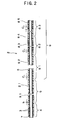
Fig. 1 is a plan view showing an entire catheter according to an embodiment of the present invention. -
Fig. 2 is a sectional view, showing the catheter shown inFig. 1 , in which a part of the catheter is unshown. -
Fig. 3 is an enlarged sectional view showing a front side of the catheter shown inFig. 1 . -
Fig. 4 is an enlarged sectional view showing a front side of a catheter according to another embodiment of the present invention. -
Fig. 5 is an enlarged sectional view showing a front side of a catheter according to still another embodiment of the present invention. - An embodiment of the catheter of the present invention will be described in detail below with reference to the accompanied drawings.
- The embodiment will be described below by setting the right end in
Figs. 1 through 3 to the "rear end" and the left end therein to the "front end". - A
catheter 1 of the embodiment has a tubularflexible body 2; and acoil 3 disposed in thebody 2 and having a reinforcing effect. Thecatheter 1 has afirst region 4 disposed at its front end and asecond region 5 disposed nearer to its rear end than thefirst region 4. Thecoil 3 extends from thefirst region 4 to thesecond region 5. In thesecond region 5, theentire coil 3 is wound at relatively long winding pitches. In thefirst region 4, the winding pitch of thecoil 3 is relatively short with the winding pitch becoming gradually or stepwise shorter toward the front end of thecatheter 1. Thereby the rigidity (flexural rigidity) of thecatheter 1 is lower in thefirst region 4 than in thesecond region 5. - The
catheter 1 of the present invention has the flexibletubular body 2 and the reinforcingcoil 3 embedded in a wall of thebody 2. Thecatheter 1 has an outer diameter not larger than 1.5mm at its front end. Thebody 2 has thefirst region 4 disposed within the range of 1 - 30mm from the front end of thecatheter 1 and thesecond region 5 nearer to the rear end of thecatheter 1 than thefirst region 4. Thecoil 3 extends from a position inside thefirst region 4 to thesecond region 5. A part of thecoil 3 disposed in thesecond region 5 is wound at long winding pitches. The winding pitch of a part of thecoil 3 disposed in thefirst region 4 is shorter than that of the part of thecoil 3 disposed in thesecond region 5. The winding pitch of the part of thecoil 3 disposed in thefirst region 4 becomes shorter gradually or stepwise toward the front end of thecatheter 1. Thereby the rigidity of thecatheter 1 is lower in thefirst region 4 than in thesecond region 5. - The
catheter 1 of a preferred embodiment of the present invention has the tubularflexible body 2 and the reinforcingcoil 3 embedded in the wall of thebody 2. Thecatheter 1 has an outer diameter not larger than 1.5mm at its front end. The front end of thecoil 3 is located within 1 - 30mm apart from the front end of thebody 2. The winding pitch of the part of thecoil 3 disposed within 1 - 30mm apart from the front end of thebody 2 becomes shorter gradually or stepwise toward the front end of thecatheter 1. - As shown in
Figs. 2 and3 , the winding pitch of thecoil 3 described in the specification means the distance between adjacent windings of thecoil 3 in the longitudinal direction of thecatheter 1. That is, the winding pitch of thecoil 3 means the length (interval) of the gap between adjacent windings of thecoil 3 in the longitudinal direction of thecatheter 1. - The
catheter 1 of the embodiment will be described below in detail with reference to the accompanied drawings. - The catheter shown in
Fig. 1 includes thebody 2 and a hub 11 mounted on the rear end of thebody 2. - The
body 2 is composed of a flexible tubular member. Alumen 21 is formed inside thebody 2 from its rear end to its front end. Thelumen 21 functions as an inner lumen for inserting a guide wire thereinto. As shown inFig. 1 , a guide wire 9 is inserted into thelumen 21 when thecatheter 1 is inserted into a blood vessel. Thelumen 21 may be used as a passage for a medicine, thrombus substance, a contrast medium. - The hub 11 functions as an insertion opening for inserting the guide wire 9 into the
lumen 21, an injection opening for injecting the medicine, thrombus substance, the contrast medium into thelumen 21, and a gripping portion of thecatheter 1 in operating it. - The
catheter 1 has thefirst region 4 and thesecond region 5 disposed nearer to the rear end of thecatheter 1 than thefirst region 4. Thefirst region 4 extends from the front end of thebody 2 to its rear end. Thesecond region 5 is adjacent to thefirst region 4 and extends from the front end of thebody 2 to its rear end. Thecatheter 1 has a third region disposed nearer to the rear end of thebody 2 than thesecond region 5. Thethird region 6 is adjacent to thesecond region 5 and extends to the rear end of thebody 2. - As shown in
Fig. 3 , thefirst region 4 of thecatheter 1 of the embodiment has a region 41 positioned at the front end of thebody 2, a region 42 positioned nearer to the rear end of thebody 2 than the region 41 and adjacent to the region 41, aregion 43 positioned nearer to the rear end of thebody 2 than the region 42 and adjacent to the region 42, aregion 44 positioned nearer to the rear end of thebody 2 than theregion 43 and adjacent to theregion 43, and a region 45 positioned nearer to the rear end of thebody 2 than theregion 44 and adjacent to theregion 44. - As shown in
Figs. 2 and3 , thecoil 3 having the reinforcing effect is embedded in thebody 2. Thecoil 3 extends from thefirst region 4 to thesecond region 5 and to thethird region 6 and reaches the rear end of thebody 2. - The
coil 3 is composed of a metal member and/or a non-metal member. For example, thecoil 3 can be composed of a spiral metal member, a spiral non-metal member or a combination of the spiral metal member and the spiral non-metal member laminated thereon. - As materials for composing the metal member, it is possible to singly use stainless steel, a nickel-titanium alloy, platinum, iridium, tungsten or a combination of two or more of these materials.
- As materials for composing the non-metal member, it is possible to singly use carbon, polyamide, polyethylene terephthalate, polybutylene terephthalate or combination containing two or more of these substances.
- It is preferable to compose the
coil 3 of a radiopaque material such as tungsten, platinum, iridium or an alloy containing these metals. As will be made later in detail in the description of the region 42, the front end of thecoil 3 can be functioned as a radiopaque marker by making the winding pitch of only the front end of thecoil 3 small in the neighborhood (region 42) of the front end of thebody 2. - The
coil 3 may be flat in its cross-sectional shape, namely, ribbon-shaped (belt-shaped) instead of the circular shape shown inFigs 2 through 5 . - In the case where the
coil 3 is circular in its cross-sectional shape, its diameter is favorably 10 - 100µm and more favorably 30 - 60µm. - In the case where the
coil 3 is ribbon-shaped in its cross-sectional shape, its width is favorably 0.1 - 1.0mm and its thickness is favorably 0.04 - 0.05mm. - The
coil 3 having the above-described shape and dimension has a sufficient reinforcing effect although it is comparatively thin. Therefore, thebody 2 can have a small diameter or can be thin by providing it with thecoil 3 having the above-described shape and dimension. - The front end of the
coil 3 is spaced rearward at a predetermined interval from the front end of thebody 2, namely, the front end of thefirst region 4. That is, at the front side of thefirst region 4, there is formed the region 41 in which thecoil 3 is not present. The front end of the region 41 is tapered. Therefore, it is possible to improve operability of inserting thecatheter 1 into the blood vessel and selectivity of a blood vessel from among branching blood vessels. - The length of the region 41 is favorably 0.5 - 5mm and more favorably 1 - 2mm.
- There is a variation in the winding pitch of a part of the
coil 3 disposed in thefirst region 4 which includes a part extending from the front end of thecatheter 1 to a position 5mm apart from the front end thereof. That is, the winding pitch of the coil in thefirst region 4 becomes gradually shorter forward from the region 45 toward the region 42 in the order of the region 45, theregion 44, theregion 43, and the region 42. The winding pitch of the part of thecoil 3 disposed in thefirst region 4 may become gradually smaller continuously or stepwise. The winding pitch of thecoil 3 in thefirst region 4 is preferably 30 - 300µm. It is preferable that the relationship between the winding pitch (S1) of thecoil 3 at the rear end of thefirst region 4 and the winding pitch (E) of thecoil 3 at its front end is E ≦ 3/4 x S1. It is also preferable that the winding pitch (M1) of thecoil 3 at the middle point between the rear end of thefirst region 4 and the front end of thecoil 3 is 0.7 x (S1+E)/2≦M1≦1.3 x (S1+E)/2. - The winding pitch of the
coil 3 disposed between the front end of thecatheter 1 and at a position within 5mm from the front end of thecatheter 1 is favorably 30 - 300µm, and more favorably 100 - 200µm. It is preferable that the relationship between the winding pitch (S2) of thecoil 3 at a position 5mm apart from the front end of thecatheter 1 and the winding pitch (E) of thecoil 3 at its front end is E≦3/4 x S2. It is also preferable that the winding pitch (M2) of thecoil 3 at the middle point between the position 5mm apart from the front end of thecatheter 1 and the front end of thecoil 3 is preferably 0.7 x (S2+E)/2≦M2≦1.3 x (S2+E)/2. - In the
catheter 1 of the embodiment, the following relationship is established among a winding pitch a1 of thecoil 3 in the region 42, a winding pitch a2 thereof in theregion 43, a winding pitch a3 thereof in theregion 44, and a winding pitch a4 thereof in the region 44: a4>a3>a2>a1. In each of theregions first region 4, thecoil 3 is wound with adjacent windings thereof not in close contact but with relatively short intervals provided between the adjacent windings thereof. In other words, even in the region 42 in which thecoil 3 is wound at the shorter pitch than any of theregions coil 3 are very close to each other but have the pitch a1 longer than zero therebetween. That is, adjacent windings of thecoil 3 are spaced at very short pitches but do not contact each other with the gap left therebetween. - On the other hand, the winding pitch of the
coil 3 in thesecond region 5 is longer than that of thecoil 3 in thefirst region 4. That is, the winding pitch b of thecoil 3 in thesecond region 5 is longer than any of the winding pitches a1, a2, a3, a4, and a5 in thefirst region 4. The winding pitch b of thecoil 3 in thesecond region 5 is almost uniform (same pitch or almost same pitch in the entire length of the second region 5). - In the
catheter 1, the winding pitch of thecoil 3 in thefirst region 4 changes toward the front end of thecatheter 1. Therefore, thefirst region 4 is more bendable (low in rigidity) and flexible than thefirst region 4 in which thecoil 3 is wound at almost regular pitches. It is conceivable that as the winding pitch of thecoil 3 becomes shorter, the rigidity of the catheter 1 (body 2) having thewound coil 3 becomes increasingly high. But by changing the winding pitch of thecoil 3 in thefirst region 4, a plurality of regions having different physical properties (rigidity, hardness) are formed in the coil-embeddedbody 2 along the longitudinal direction thereof. Thereby the rigidity of thefirst region 4 the winding pitch becomes shorter toward the front end of the catheter is lower than that of thefirst region 4 having thecoil 3 wound at regular pitches. Accordingly, although the winding pitch of thecoil 3 in thefirst region 4 is shorter than that of thecoil 3 in thesecond region 5, thecatheter 1 has a lower rigidity in thefirst region 4 than in thesecond region 5. - By disposing the
coil 3 wound at relatively shorter pitches in thefirst region 4, thecatheter 1 has a high kink resistance and a high pressure resistance in thefirst region 4. - Because the
coil 3 extends from thefirst region 4 to thesecond region 5, there is no sudden change in the rigidity (flexural rigidity) of thecatheter 1 at the boundary between thefirst region 4 and thesecond region 5. Thus, there is no fear that thecatheter 1 is kinked or bent at the boundary between thesecond region 5 having the higher rigidity and thefirst region 4 having the lower rigidity. - As apparent from the above description, the rigidity of the
catheter 1 is lower in thefirst region 4 than in thesecond region 5. That is, in thesecond region 5, thecatheter 1 has a sufficient rigidity and excellent pressing performance, whereas in thefirst region 4 which is located at the front end of thecatheter 1, thecatheter 1 is flexible and bendable, has excellent follow-up performance, and in addition a high kink resistance and pressure resistance. - The front end of the
coil 3 disposed in the region 42 of thefirst region 4 is wound at very short pitches a1. Therefore, the front end of thecoil 3 can be composed of the radiopaque marker to allow the front end thereof to be visible under the presence of an X-ray. Thereby it is possible to function the front end of thecoil 3 as the radiopaque marker for recognizing the position of thecatheter 1 under the presence of the X-ray. - In the
catheter 1 having the above-described construction, it is unnecessary to mount the radiopaque marker separate from thecoil 3 and having a high rigidity on thefirst region 4 low in rigidity (flexibility) and bendable to recognize thecatheter 1 under the presence of the X-ray. Accordingly, unlike the conventional catheter, the bendability (flexibility) of thecatheter 1 having the above-described construction does not deteriorate because it is unnecessary to mount the radiopaque marker having a high rigidity on thefirst region 4. Thus, thecatheter 1 has superior follow-up performance and visibility of thecatheter 1 under the presence of the X-ray. - The manner of winding the
coil 3 in thefirst region 4 is not limited to that of the embodiment, provided that its winding pitch decreases continuously or stepwise. For example, in each of theregions coil 3 uniformly, but it is possible to set the winding pitch thereof gradually shorter toward the front end of thecatheter 1. Otherwise, it is possible to set the winding pitch of thecoil 3 continuously (stepless) shorter from the rear end of thefirst region 4 toward its front end. In the embodiment, in thefirst region 4 having theregions coil 3 is varied at three or more steps, namely, at four steps, but may be varied at two steps, three steps or five or more steps. - The winding pitch of the
coil 3 in thesecond region 5 is not necessarily uniform in the entire range thereof, but may be almost uniform as compared with the change of the winding pitch in thefirst region 4. That is, the pitch in thesecond region 5 is uniform in the entire range thereof or slightly varied in the longitudinal direction of thecatheter 1. In other words, so long as thesecond region 5 has a higher rigidity than thefirst region 4, a slight change of the winding pitch of thecoil 3 is permitted in thesecond region 5 in the longitudinal direction of thecatheter 1. However, if there is a sudden change in the winding pitch of thecoil 3 in the longitudinal direction of thecatheter 1, a plurality of regions having different physical properties (rigidity) are formed in thesecond region 5. Consequently, there is a possibility that thesecond region 5 has a lower rigidity than thefirst region 4. In this case, it is difficult to transmit a pressing force applied to the rear end of thecatheter 1 to thefirst region 4. Accordingly, the degree of the change of the winding pitch of thecoil 3 in thesecond region 5 is required to be lower than the degree of the change of the winding pitch thereof in thefirst region 4. The part of thecoil 3 disposed in thefirst region 4 is integral with the part of thecoil 3 disposed in thesecond region 5. - As shown in
Fig. 2 , in thecatheter 1 of the embodiment, thethird region 6 has a part 61 positioned at the front end thereof, apart 62 positioned nearer to the rear end of thecatheter 1 than the part 61 and adjacent to the part 61, and a part 63 positioned nearer to the rear end of the catheter than thepart 62 and adjacent to thepart 62. - The winding pitch of the
coil 3 in thethird region 6 becomes gradually longer toward the rear end of thecatheter 1 in order of theparts 61, 62, and 63. That is, the following relationship is established among a winding pitch c1 of thecoil 3 in the part 61, a winding pitch c2 thereof in thepart 62, a winding pitch c3 thereof in the part 63: c1<c2<c3. - The winding pitch of the
coil 3 in thethird region 6 is longer than the winding pitch thereof in thesecond region 5. That is, any of the winding pitches c1, c2, and c3 of thecoil 3 in thethird region 6 are longer than the winding pitch b of thecoil 3 in thesecond region 5. - Thereby the winding direction of the
coil 3 in thethird region 6 is closer to the axial (longitudinal) direction of thecatheter 1 than that of thecoil 3 in thesecond region 5. Thus, thecoil 3 disposed in thethird region 6 allows thecatheter 1 to have a higher rigidity. Accordingly, the rigidity of thecatheter 1 becomes lower in order of thethird region 6, thesecond region 5, and thefirst region 4. - The rigidity of the
third region 6 is gradually increased by making the winding pitch of thecoil 3 in thethird region 6 gradually longer (continuously or stepwise) toward the rear end of thecatheter 1. In other words, the rigidity of thethird region 6 decreases gradually toward the front end of thecatheter 1. By varying the winding pitch of thecoil 3 in this manner, it is possible to decrease the rigidity of thecatheter 1 continuously toward its front end. - In the
catheter 1, thesecond region 5 and thethird region 6 have a sufficient degree of rigidity and high pressing performance. Further, thefirst region 4 has superior follow-up performance and safety and in addition high pressure resistance and kink resistance. Furthermore, because thecoil 3 extends in thefirst region 4, thesecond region 5, and thethird region 6, there is no sudden change in the rigidity of thecatheter 1 at the boundary between thefirst region 4 and thesecond region 5 and the boundary between thesecond region 5 and thethird region 6. Thus, there is no fear that the boundaries are kinked or bent. - The part of the
coil 3 disposed in thefirst region 4 is integral with the part of thecoil 3 disposed in thesecond region 5 andthird region 6. - As described above, it is possible to decrease the rigidity (mechanical property) of the
catheter 1 gradually toward the front end of thecatheter 1 by merely varying the winding pitch of thecoil 3 in the longitudinal direction of thecatheter 1. - The length of each of the
first region 4, thesecond region 5, and thethird region 6 is varied according to the use of thecatheter 1 and not limited to a specific length. The following ranges are favorable for a micro-catheter for administering or injecting various medicines, a thrombus substance or a contrast medium to a desired portion in the internal organs such as brain or belly(for example, liver). - That is, the length of the
first region 4 is favorably 1-30mm and more favorably 2-10mm. The length of thesecond region 5 is favorably 50-500mm and more favorably 100-300mm. The length of thethird region 6 is favorably 500-1500mm and more favorably 700-1000mm. In particular, in the case where thefirst region 4 is located in the length not less than 5mm from the front end of thebody 2, thecatheter 1 is sufficiently flexible (low in rigidity) in thefirst region 4. Thus, in advancing thecatheter 1 to a desired portion of a blood vessel (lumen), thefirst region 4 can flex sufficiently along the curvature of the guide wire 9 (seeFig. 1 ). That is, it is possible to improve the follow-up performance of thecatheter 1. - The winding pitch of the
coil 3 in thefirst region 4 is not limited to a specific dimension. The winding pitch a1 of thecoil 3 at its front end (in the embodiment, the winding pitch in the region 42) in thefirst region 4 is favorably 30-200µm and more favorably 50-100µm. The winding pitch a4 of thecoil 3 at its rear end (in the embodiment, the winding pitch in the region 45) in thefirst region 4 is favorably 50-300µm and more favorably 100-200µm. By varying the winding pitch of thecoil 3 within this range toward the front end of thefirst region 4, thecatheter 1 is sufficiently flexible (low in rigidity) in thefirst region 4. Thus, in advancing thecatheter 1 to a desired portion of a blood vessel (lumen), thefirst region 4 can flex sufficiently along the curvature of the guide wire 9 (seeFig. 1 ). That is, it is possible to improve the follow-up performance of thecatheter 1. - The winding pitch of the
coil 3 disposed in thesecond region 5 is favorably 100-500µm and more favorably 150-250µm. The winding pitch of thecoil 3 disposed in thethird region 6 is favorably 200-1000µm and more favorably 250-400µm. - In the case where the winding pitch of the
coil 3 in each of thefirst region 4, thesecond region 5, and thethird region 6 is in the above-described range, it is possible to impart a proper rigidity to thebody 2 and allow thecatheter 1 to have preferable flexibility (follow-up performance), kink resistance, and pressure resistance in thefirst region 4. - The position of the front end of the
coil 3 disposed in the region 42 can be easily recognized under the presence of the X-ray by setting the winding pitch of thecoil 3 to the above-described range in the region 42 and composing thecoil 3 of the radiopaque material. - As the material of the
body 2, the following flexible materials are used: polyolefins such as polypropylene, ethylene-vinyl acetate copolymer; polyamide, polyesters such as polyamide, polyethylene terephthalate (PET), polybutylene terephthalate (PBT); fluorocarbon resins such as polytetrafluoroethylene, ethylene-tetrafluoroethylene copolymer; polyurethane, polyvinyl chloride, polystyrene resin, flexible resins such as polyamide elastomer, polyurethane elastomer, polystyrene elastomer, polyester elastomer, fluoro-elastomer; rubber materials such as silicone rubber, latex rubber; and combinations of two or more of these substances. - The
body 2 has a rear section and a front section disposed forward from the rear section. It is preferable that the front section has a lower rigidity than the rear section. To do so, the rear section of thebody 2 is composed of a material having a comparatively high rigidity and the front section is composed of a material having a comparatively low rigidity by selecting them from among the above-described materials for thebody 2. It is particularly preferable that the front section having a low rigidity is formed throughout thefirst region 4. Thereby it is possible to compose thefirst region 4 more bendably and flexibly (low rigidity) and allow thecatheter 1 to have improved follow-up performance. - Owing to this construction and the change of the winding pitch of the
coil 3, it is possible to decrease the rigidity of thecatheter 1 continuously toward the front end thereof. In other words, even though thefirst region 4 is so constructed that it has a low rigidity in thefirst region 4, thecatheter 1 has high kink resistance and pressure resistance. This is because the winding pitch of thecoil 3 in thefirst region 4 is relatively low. Accordingly, thecatheter 1 thus constructed displays high pressing performance and torque transmission performance at the rear side of thecatheter 1 and has superior flexibility and follow-up performance and in addition high kink resistance and pressure resistance at the front side thereof. - In the embodiment, the
body 2 has an inner layer 7 and anouter layer 8. Thecoil 3 is interposed between the inner layer 7 and theouter layer 8. - The
outer layer 8 is provided on the outer side of thecoil 3 to cover thecoil 3. As shown inFigs. 2 and3 , a part of the outer layer 8 (inner peripheral part of the outer layer 8) in its thickness direction is in penetration between adjacent windings of thecoil 3 in thefirst region 4, thesecond region 5, and thethird region 6. Owing to the penetration of a part of thecoil 3 between the adjacent windings of thecoil 3 and the variation of the winding pitch of thecoil 3, in thefirst region 4, theouter layer 8 has a plurality of regions having different physical properties (rigidity, hardness) in its longitudinal direction. Thus, thefirst region 4 is bendable (low in rigidity) and flexible. Accordingly, although the winding pitch of thecoil 3 in thefirst region 4 is shorter than the winding pitch thereof in thesecond region 5, thecatheter 1 is so constructed that the rigidity thereof is lower in thefirst region 4 than in thesecond region 5. - As the material of the
outer layer 8, the following flexible materials are used: polyolefins such as polypropylene, ethylene-vinyl acetate copolymer; polyamide, polyesters such as polyethylene terephthalate (PET), polybutylene terephthalate (PBT); fluorocarbon resins such as polytetrafluoroethylene, ethylene-tetrafluoroethylene copolymer; polyurethane, polyvinyl chloride, polystyrene resin, flexible resins such as polyamide elastomer, polyurethane elastomer, polystyrene elastomer, polyester elastomer, fluoro-elastomer; rubber materials such as silicone rubber, latex rubber; and combinations of two or more of these substances. - In the embodiment, the
outer layer 8 has afirst part 81 disposed at the front end of thecatheter 1, asecond part 82 disposed nearer to the rear end of thecatheter 1 than thefirst part 81, a third part 83 disposed nearer to the rear end of thecatheter 1 than thesecond part 82, a fourth part 84 disposed nearer to the rear end of thecatheter 1 than the third part 83, afifth part 85 disposed nearer to the rear end of thecatheter 1 than the fourth part 84. Thereby theouter layer 8 is divided into a rear section consisting of the third part 83, the fourth part 84, and thefifth part 85; and a front section consisting of thefirst part 81 and thesecond part 82 and disposed nearer to the front end of thecatheter 1 than the rear section. - These parts are so arranged that the hardnesses (rigidity) of materials composing these parts decrease continuously or stepwise from the rear end of the
outer layer 8 to its front end, namely, in the order of thefifth part 85, the fourth part 84, the third part 83, thesecond part 82, and thefirst part 81. Thereby the front section (section consisting of thefirst part 81 and the second part 82) of theouter layer 8 has a lower rigidity than the rear section (section consisting of thefifth part 85, the fourth part 84, and the third part 83) of theouter layer 8. As shown inFigs. 2 and3 , the front section (section consisting of thefirst part 81 and the second part 82) of theouter layer 8 having the lower rigidity extends throughout thefirst region 4. Thereby it is possible to compose thefirst region 4 bendably and flexibly (low in rigidity) and allow thecatheter 1 to have improved follow-up performance. - Owing to the construction that the front section of the
outer layer 8 has a lower rigidity than the rear section thereof and the change of the winding pitch of thecoil 3, it is possible to decrease the rigidity of thecatheter 1 continuously toward the front end thereof. In other words, even though theouter layer 8 is so constructed that it has a low rigidity in thefirst region 4, thecatheter 1 has high kink resistance and pressure resistance. This is because the winding pitch of thecoil 3 in thefirst region 4 is relatively low. Accordingly, thecatheter 1 thus constructed displays high pressing performance and improved torque transmission performance at the rear side of thecatheter 1 and displays superior flexibility and follow-up performance and in addition high kink resistance and pressure resistance at the front side thereof. - As shown in
Fig. 2 and3 , the front end and rear end of each of thefirst part 81, thesecond part 82, the third part 83, the fourth part 84, and thefifth part 85 are not coincident with the front end and rear end of each of thefirst region 5, thesecond region 5, and thethird region 6 in the longitudinal direction of thecatheter 1. This construction allows the rigidity of thecatheter 1 to decrease continuously toward the front end of thecatheter 1. Accordingly, the bending rigidities of the respective regions of thebody 2 balance favorably with each other. In particular, the construction allows the rear side of thebody 2 to have a sufficient rigidity and thus allows it to display high pressing performance and torque transmission performance and also allows the front side of thebody 2, particularly thefirst region 4 to display high follow-up performance, kink resistance, and safety. - The hardness of the front section of the
outer layer 8, namely, the hardness of each of the first andsecond parts outer layer 8 is not limited to a specific value. However, the Shore D hardness thereof is favorably in the range of 10 to 60 and more favorably in the range of 20 - 50. - The hardness of the rear section of the
outer layer 8, namely, the hardness of each of the fifth, fourth, andthird parts 85, 84, and 83 of theouter layer 8 is not limited to a specific value. However, the Shore D hardness thereof is favorably in the range of 60 to 80 and more favorably in the range of 62 - 75. By setting the hardness thereof to the above-described range, thecatheter 1 has the pressing performance, the torque transmission performance, the follow-up performance, and the kink resistance balancing well with each other. - The thickness of the
outer layer 8 is not limited to a specific dimension. The thickness of theouter layer 8 is favorably in the range of 0.05 to 0.15mm and more favorably in the range of 0.06 to 0.12mm. If the thickness of theouter layer 8 is smaller than the lower limit value, there may be a case in which the pressing performance and the torque transmission performance are not displayed sufficiently. On the other hand, theouter layer 8 having a thickness larger than the upper limit value has a disadvantage in making the diameter of thebody 2 small. - As shown in
Fig. 2 , in the embodiment, theouter layer 8 is so constructed that its thickness is almost uniform from the rear end of thebody 2 to its front end, but may decrease gradually toward the front end of thebody 2. Thereby the rigidity (bending rigidity) of thecatheter 1 decrease continuously. Therefore, thebody 2 has improved follow-up performance and kink resistance. - The length of each of the
first part 81, thesecond part 82, the third part 83, the fourth part 84, and thefifth part 85 is varied according to the kind of the catheter and not limited to a specific length. The following ranges are favorable for a micro-catheter for administering or injecting various medicines, a thrombus substance or a contrast medium to a desired portion of the internal organs such as brain or belly (for example, liver). - The length of the
first part 81 of theouter layer 8 is favorably in the range of 5 to 100mm. The length of thesecond part 82 of theouter layer 8 is favorably in the range of 30 to 200mm. The length of the third part 83 of theouter layer 8 is favorably in the range of 30 to 100mm. The length of the fourth part 84 of theouter layer 8 is favorably in the range of 30 to 100mm. The length of thefifth part 85 of theouter layer 8 is favorably in the range of 300 to 1500mm. - The construction of the
outer layer 8 is not limited to that of the embodiment. For example, theouter layer 8 may be formed of the same material and may have the same rigidity (hardness) from the front end thereof 2 to its rear end. - It is preferable that the outer layer has the front section and the rear section, that the front section is composed of a polyester elastomer, and that the rear section is composed of a polyurethane elastomer having a higher rigidity than the polyester elastomer.
- By composing the outer layer thus, while the operability of the catheter such as the pressing performance, the torque transmission performance, the follow-up performance, and kink resistance is secured, a hydrophilic polymeric substance can be preferably imparted to the outer surface of the catheter. The front section of the outer layer is formed from the front end of the
body 2 to a position spaced at a certain interval from the front end of thebody 2. The rear section of the outer layer is formed continuously with the front section and terminates at arear end 21 of thebody 2. - It is preferable that the front section of the outer layer has a plurality of parts and that the hardness (rigidity) of a material composing each part of the front section of the outer layer decreases continuously or stepwise from the rear end of the front section toward its front end. It is also preferable that the hardness (rigidity) of the entirety of the
outer layer 8 decreases continuously or stepwise from the rear end thereof toward the front end thereof. - The
catheter 1 in which the outer layer is composed as described above allows the bending rigidities of the respective regions of thebody 2 to balance favorably with each other. In particular, it is possible to allow thesecond region 5 to have a sufficient rigidity and thus display high pressing performance and torque transmission performance and allow thefirst region 4 to have high follow-up performance, kink resistance, and safety. - It is preferable that the front section of the
outer layer 8 is composed of the polyester elastomer and that rear section of theouter layer 8 is composed of the polyurethane elastomer. - The hardness of the polyester elastomer is not limited to a specific value. However, the Shore D hardness thereof is favorably in the range of 25 to 60 and more favorably in the range of 28 - 55. The polyurethane elastomer for the rear section of the outer layer has a higher hardness than the polyester elastomer for the first region. The hardness of the polyurethane elastomer is not limited to a specific value. The Shore D hardness thereof is favorably in the range of 60 to 80 and more favorably in the range of 62 to 75.
- By setting the hardness of the polyester elastomer and the polyurethane elastomer to the above-described range, the
catheter 1 has pressing performance, torque transmission performance, follow-up performance, and kink resistance balancing well with each other. - As the polyester elastomer composing the front section of the outer layer, it is possible to use a copolymer (random copolymer, block copolymer and the like) containing a hard segment and a soft segment.
- As the hard segment, polybutylene terephthalate, polyethylene terephthalate, dihidroxyparaquarterphenyl can be used. The polybutylene terephthalate is more favorable than the other substances.
- As the soft segment, it is possible to use polytetramethylene terephthalate, polytetramethylene ether glycol, poly (1,2-propylene oxide) glycol, poly (ethylene oxide) glycol, and polycaprolactam. The polytetramethylene terephthalate and the polytetramethylene ether glycol are more favorable than the other substances.
- As the polyurethane elastomer composing the rear section of the outer layer, it is possible to use a copolymer (random copolymer, block copolymer and the like) containing a hard segment and a soft segment.
- As the hard segment, polymers containing diisocyanate and short-chain glycol can be used.
- As the diisocyanate, the following substances can be used: 4,4'-diphenylmethanediisocyanate, 2,4'-toluenediisocyanate, 2,6-toluenediisocyanate, 1,6-hexamethylenediisocyanate, 3,3'-dimethyldiphenyl-4,4'-diisocyanate, 1,5'-naphthalanediisocyanate. Of these substances, the 4,4'-diphenylmethanediisocyanate is more favorable than the other substances.
- As the short-chain glycol, it is possible to use 1,4-butanediol, ethylene glycol; 1,3-propylene glycol; 1,3-butylene glycol; 1,4-butylene glycol; 1,6-hexyl glycol; 1,4-dimethylol benzene; and bisphenol A. Of these short-chain glycols, the 1,4-butanediol is more favorable than the other short-chain glycols.
- As the soft segment, it is possible to use polymers containing diisocyanate and long-chain glycol or use only the long-chain glycol.
- As the diisocyanate, it is possible to use the same substances as those which can be used for the hard segment. Of those substances, the 4,4'-diphenylmethanediisocyanate is more favorable than the other substances.
- As the long-chain glycols, the following substances can be used: polytetramethylene ether glycol, poly (oxypropylene) glycol, poly (ethylene adipate) glycol, poly (butylene-1,4-adipate) glycol, poly (ethylene-1,4-adipate) glycol, poly (hexanediol-1,6-carbonate) glycol, polycaprolactam glycol, poly (diethylene glycol adipate) glycol, and (hexanediol-1,6-carbonate) glycol. Of these substances, the polytetramethylene ether glycol is more favorable than the other glycols.
- By composing the
outer layer 8 of the polyester elastomer and the polyurethane elastomer, it is easy to impart a hydrophilic polymeric substance which will be described later to the outer surface of theouter layer 8 and hold the hydrophilic polymeric substance thereon. - The thickness of the
outer layer 8 is not limited to a specific value. The thickness of theouter layer 8 is favorably in the range of 0.05 to 0.15mm and more favorably in the range of 0.06 to 0.12mm. If the thickness of theouter layer 8 is smaller than the lower limit value, there may be a case in which the pressing performance and the torque transmission performance are not displayed sufficiently. On the other hand, theouter layer 8 having a thickness larger than the upper limit value is at a disadvantage in making the diameter of thebody 2 small. - As shown in
Fig. 2 , in the embodiment, the thickness of theouter layer 8 is almost uniform from the rear end of thebody 2 to its front end, but may decrease gradually toward the front end of thebody 2. Thereby the rigidity (bending rigidity) of thebody 2 decrease continuously. Therefore, the body has improved follow-up performance and kink resistance. - The inner layer 7 covers the inner side of the
coil 3. The inner layer 7 serves as the core for disposing thecoil 3 in thebody 2 and forms alumen 21 therein. - As the material for the inner layer 7, it is possible to use a material similar to that for the
outer layer 8. It is preferable to compose the inner layer 7 of a material having a low friction coefficient to allow the inner surface of the inner layer 7 to have a low degree of friction. Thereby it is possible to reduce the sliding-contact resistance of the inner layer 7 to the guide wire 9 (seeFig. 1 ) inserted into thelumen 21. Thus, it is possible to easily and smoothly perform an operation of inserting thecatheter 1 into a blood vessel along the guide wire precedent to the front end of thecatheter 1 and an operation of pulling out the guide wire from thecatheter 1. - Any material having a low friction coefficient can be used for the inner layer 7, so long as it can reduce the friction of the inner surface of the inner layer 7. For example, it is possible to use fluorocarbon resin, nylon 66, polyether ether ketone, and high-density polyethylene. The fluorocarbon resin is more favorable than the other substances.
- As the fluorocarbon resin, the following substances can be used: polytetrafluoroethylene, polyvinylidene fluoride, ethylene tetrafluoroethylene, and perfluoroalcoxy resin. The polytetrafluoroethylene is more favorable than the other substances.
- The thickness of the inner layer 7 is not limited to a specific value, but is favorably less than 50µm and more favorably less than 40µm. The inner layer 7 having a thickness larger than the upper limit value is at a disadvantage in making the diameter of the
body 2 small. - As shown in
Figs. 2 and3 , a part of the inner layer 7 (outer peripheral part of the inner layer 7) in its thickness direction is in penetration between adjacent windings of thecoil 3 in thefirst region 4, thesecond region 5, and thethird region 6. Owing to the penetration of a part of thecoil 3 between the adjacent windings of thecoil 3 and the variation of the winding pitch of thecoil 3, in thefirst region 4, the inner layer 7 has a plurality of regions having different physical properties (rigidity, hardness) in its longitudinal direction. Thus, thefirst region 4 is bendable (low in rigidity) and flexible. Accordingly, although the winding pitch of thecoil 3 in thefirst region 4 is shorter than the winding pitch thereof in thesecond region 5, thecatheter 1 is so constructed that the rigidity thereof is lower in thefirst region 4 than in thesecond region 5. - In the case where the inner layer 7 has a higher rigidity than the
outer layer 8 in thefirst region 4, the rigidity of the inner layer 7 having the higher rigidity acts mainly in thefirst region 4 as the entire rigidity of thecatheter 1. But the inner layer 7 is in penetration between the windings of thecoil 3. Thus, with the change of the winding pitch of thecoil 3, the inner layer 7 is bendable and flexible (low in rigidity). Thereby the rigidity of the inner layer 7 in thefirst region 4 can be preferably reduced. Thus, thecatheter 1 has a reduced rigidity in thefirst region 4 and is thus bendable. - In the embodiment, the
coil 3 is wound on the periphery of the inner layer 7 by cutting thecoil 3 into the periphery of the inner layer 7. Accordingly, the periphery of the inner layer 7 is compressed by thewound coil 3. It is possible to preferably penetrate the inner layer 7 between the adjacent windings of thecoil 3 by winding thecoil 3 in this manner. - For example, the catheter
main body 2 that mentioned above can manufacture it by the method that expresses below. - Initially, the inner layer 7 is mounted on the periphery of a mandrel (core material). The inner layer 7 can be formed by hollow extrusion molding, wire-coating molding or applying (or immersing) a solution containing a material for the inner layer 7 to the periphery of the core material and drying the solution.
- Then, a wire, namely, the
coil 3 is wound spirally on the periphery of the inner layer 7 by varying the winding pitch of thecoil 3 in the longitudinal direction of the mandrel to mount thecoil 3 on the periphery of the inner layer 7. In the winding operation, the wire is wound onto the periphery of the inner layer 7, with a predetermined winding tensile force applied to the wire. Thereby the inner layer 7 is compressed by thewound coil 3 and penetrates between the adjacent windings of thecoil 3. - Then, the
first part 81, thesecond part 82, the third part 83, the fourth part 84, and thefifth part 85 of theouter layer 8 are prepared as hollow tubular bodies by hollow extrusion molding more favorable than the wire-coating molding or wire-coating molding. The hardness, thickness, and length of each of thefirst part 81, thesecond part 82, the third part 83, the fourth part 84, and thefifth part 85 of theouter layer 8 are set to a predetermined value, respectively. - Then, the
first part 81, thesecond part 82, the third part 83, the fourth part 84, and thefifth part 85 of theouter layer 8 are applied to the core material on which the inner layer 7 and thecoil 3 have been mounted in a predetermined order. - A heat-shrinkable tube is applied to the
first part 81, thesecond part 82, the third part 83, the fourth part 84, and thefifth part 85 of theouter layer 8. Then, the heat-shrinkable tube is heated to thermally shrink it. The heat-shrinkable tube preferable consists of fluorocarbon resin. - Thereby the material composing each of the
first part 81, thesecond part 82, the third part 83, the fourth part 84, and thefifth part 85 of theouter layer 8 melts at the boundary between thefirst part 81 and thesecond part 82, between thesecond part 82 and the third part 83, between the third part 83 and the fourth part 84, and between the fourth part 84 and thefifth part 85. Consequently, thefirst part 81, thesecond part 82, the third part 83, the fourth part 84, and thefifth part 85 of theouter layer 8 become integral with each other. At the same time, the melted first, second, third, fourth, andfifth parts outer layer 8 flow (penetrate) into the gap between the adjacent windings of thecoil 3 and adhere to the periphery of the inner layer 7. In this manner, the inner layer 7 and theouter layer 8 become integral with each other. - Then, the heat-shrinkable tube is removed from the first, second, third, fourth, and
fifth parts outer layer 8. Then, the end (unnecessary portion of the body 2) of the semi-finished product is cut off. Then, the mandrel is pulled out from the semi-finished product before or after the cut-off operation. - As other methods of forming the
outer layer 8, extrusion molding method or dipping method may be used to apply a material for theouter layer 8 to the outer side of thecoil 3 and the inner layer 7. - A hydrophilic polymeric substance which will be described later is imparted to a predetermined portion of the outer surface of the
catheter body 2 manufactured in this manner. - Thereafter, the front end of the
body 2 is tapered and the hub 11 is mounted on its rear end to complete the manufacture of thecatheter 1. - In this invention, the outside diameter of the front end of catheter 1 (catheter main body 2) is 1.5 mm or less, and are 1.0 mm or less desirably.
- The outer diameter of the
body 2 is not limited to a specific dimension. In the case where thecatheter 1 is used as a micro-catheter for administering or injecting various medicines, a thrombus substance or a contrast medium to a desired portion of the internal organs (for example, liver) such as brain or belly, it is preferable to set the outer diameter of thebody 2 to the range of 0.5 to 1.0mm. - The outer diameter of the
body 2 is not limited to the range of 0.5 to 1.0mm in the case where the catheter of the present invention is not used as the micro-catheter. - It is preferable to apply the hydrophilic polymeric substance to the outer surface of the front side of the
outer layer 8. Thereby the outer surface of thebody 2 displays lubricity when it contacts a aqueous liquid such as blood or physiologic saline. Thus the body has a decreased frictional and improved sliding performance. Consequently, thecatheter 1 can be inserted into a blood vessel with high operability, namely, with high pressing performance, follow-up performance, kink resistance, and safety. - In the operation of inserting the
catheter 1 into a blood vessel, it is necessary to hold the rear end of thebody 2 in hand. The operability of inserting thecatheter 1 into the blood vessel deteriorates if the rear end of thebody 2 is slippery. In consideration of this, it is preferable to apply the hydrophilic polymeric substance not to the entirety of thebody 2 in the longitudinal direction of thebody 2 but to the region thereof except a predetermined range (for example, 150 - 500mm) forward from the rear end of thebody 2. - As the hydrophilic polymeric substance, the following natural or synthetic polymeric substances or derivatives of the polymeric substances can be used: a cellulose type polymeric substance (for example, hidroxypropyl cellulose), a polyethylene oxide polymeric substance (polyethylene glycol), a maleic anhydride type polymeric substances (for example, maleic anhydride copolymer such as methylvinyl ether maleic anhydride copolymer, copolymer of methyl vinyl ether and maleic anhydride ethyl ester, half-ester methyl vinyl ether-maleic anhydride copolymer neutralized, an acrylamide type polymeric substance (for example, polyacrylamide, dimethyl acrylamid-glycidyl methacrylate copolymer), and water-soluble nylon (for example, AQ-nylon P-70 manufactured by Toray Corp.). These polymeric substances are favorable because the friction coefficients thereof are stable. The maleic anhydride polymeric substance can be used more favorably than the other substances.
- The derivatives of the polymeric substances are not limited to water-soluble ones but water-insoluble ones can be also used, provided that they contain the polymeric substances as their fundamental component and that they are able to contain water and the molecular chains thereof have degree of freedom.
- To fix the hydrophilic polymeric substance to the outer surface of the
body 2, it is preferable to covalently bond it to a reactive functional group present in theouter layer 8 or on the surface thereof or introduced thereinto. Thereby it is possible to allow the outer surface of thebody 2 to keep good lubricity. - Any reactive functional groups present in the
outer layer 8 or on the surface thereof or introduced thereinto can be used, provided that they react with the hydrophilic polymeric substance and combine with each other or cross-linked to each other and are then fixed to the outer surface of thebody 2. As the reactive functional groups, the following substances can be used: diazonium group, azide group, isocyanate group, acid chloride group, acid anhydride group, imino carbonate group, amino group, carboxylic group, epoxy group, hydroxyl group, and aldehyde group. Of these groups, the isocyanate group, the amino group, the aldehyde group, and the epoxy group are more favorable than the other groups. - The present invention is not limited to the embodiment described above with reference to
Figs. 1 through 3 . - For example, the tubular member (body 2) of the present invention is not limited to the construction, of the above-described embodiment, having the inner layer and the outer layer. As shown in
Fig. 4 , the body 2 (tubular member) may have asingle layer 301 in which thecoil 3 is embedded.Fig. 4 is an enlarged sectional view showing the front side of the catheter according to another embodiment of the present invention. Thecatheter 30 has an effect similar to that of thecatheter 1 shown inFigs. 1 through 3 . Thecatheter 30 is different from thatcatheter 1 in only the above-described construction. In other points, thecatheter 30 has the same construction as that of thecatheter 1 described with reference toFigs. 1 through 3 . - The construction of the tubular member (body 2) of the present invention is not limited to the construction having both the inner layer and the outer layer penetrating between adjacent windings of the
coil 3. For example, as shown inFig. 5 , in acatheter 40, only the inner layer 7 penetrates between the adjacent windings of thecoil 3, whereas theouter layer 8 provided on the outer side of thecoil 3 does not penetrate between the adjacent windings of thecoil 3.Fig. 5 is an enlarged sectional view showing the front side of the catheter according to another embodiment of the present invention. In thecatheter 40, theouter layer 8 is liquid-tightly fixed to the periphery of the inner layer 7 with an adhesive agent or fused thereto in the region 41 disposed forward from the front end of thecoil 3. Thecatheter 40 has also an effect similar to that of thecatheter 1 shown inFigs. 1 through 3 . Thecatheter 40 is different from thatcatheter 1 in the above-described construction. In other points, thecatheter 40 has the same construction as that of thecatheter 1 described with reference toFigs. 1 through 3 . In addition, although not shown, the catheter of the present invention can be so constructed that only theouter layer 8 penetrates between the adjacent windings of thecoil 3, whereas the inner layer 7 provided on the inner side of thecoil 3 does not penetrate between the adjacent windings of thecoil 3. Further, in addition to the inner layer 7 and theouter layer 8, the catheter may have one layer or two or more layers in addition to the inner layer 7 and theouter layer 8. - The catheter of the present invention is not limited to a specific application. It can be used as a guiding catheter; a contrast medium-introducing catheter; balloon catheters such as for PTCA, PTA, IABP; an ultrasonic wave catheter, an atherectomy catheter, a catheter for an endoscope, an indwelling catheter, a medicine-administering catheter, a micro-catheter (for embolization) for administering or injecting various medicines, a thrombus substance or a contrast medium to a desired portion of the internal organs (for example, liver) such as brain or belly. The catheter of the present invention is particularly advantageous because it can have a small diameter. The catheter having a small diameter can display the above-described effect efficiently.
- Therefore, it is preferable to use the catheter of the present invention as the micro-catheter.
- The examples of the present invention will be described below.
- Polytetrafluoroethylene was applied to a mandrel (core material) made of silver-plated soft copper wire having a diameter of 0.65mm by molding to form the inner layer 7 having a thickness of 35µm on the peripheral surface of the mandrel.
- The peripheral surface of the inner layer 7 was chemically treated with a solution consisting of a glicolic solvent and a solute of naphthalene complex of sodium salt.
- Then, the core material coated with the inner layer 7 was cut to a length of 1500mm.
- A metal wire material of tungsten having a diameter of 50µm was wound on the peripheral surface of the inner layer 7 by changing a winding pitch with a winding tensile force kept at 0.17kg to form the
coil 3. - The end of the metal wire material forming the
coil 3 was cut off. - The
outer layer 8 was formed on the peripheral surface of the inner layer 7 formed on the core material and on thecoil 3 formed on the peripheral surface of the inner layer 7 as follows: - Initially, the
first part 81, thesecond part 82, the third part 83, the fourth part 84, and thefifth part 85 of theouter layer 8 were formed as hollow tubular members by extrusion molding. - Then, the
first part 81, thesecond part 82, the third part 83, the fourth part 84, and thefifth part 85 of theouter layer 8 were placed in a predetermined order on the core material on which thefirst layer 4 and thesecond layer 5 were formed. - Then, a heat-shrinkable tube (FEP) made of fluorocarbon resin was applied to the peripheral surface of the
first part 81, thesecond part 82, the third part 83, the fourth part 84, and thefifth part 85 of theouter layer 8. Both ends of the heat-shrinkable tube was fixed with a stopper. - Then, the semi-finished product was passed into a heat tunnel for 10 minutes at 340°C to fuse and connect the
first part 81 and thesecond part 82 to each other, thesecond part 82 and the third part 83 to each other, the third part 83 and the fourth part 84 to each other, and the fourth part 84 and thefifth part 85 to each other. - Then, the heat-shrinkable tube was separated from the
outer layer 8. Then, the part of the semi-finished product on which theouter layer 8 was not present was cut in a length of 200 mm from the end thereof. The mandrel was pulled out from the semi-finished product. In this manner, thebody 2 having thefirst region 4 consisting of the region, 41, 42, 43, 44, and 45; thesecond region 5, and thethird region 6 consisting of theparts 61, 62, and 63 was prepared. - The detail of each of the first region 4 (region, 41, 42, 43, 44, and 45), the
second region 5, and the third region 6 (parts 61, 62, and 63), thefirst part 81, thesecond part 82, the third part 83, the fourth part 84, and thefifth part 85 of theouter layer 8 is as follows: - <
First Region 4>
The length of the region 41: 1.0mm
The length of the region 42: 0.9mm
The winding pitch a1 of thecoil 3 in the region 42: 95µm
The length of the region 43: 1.3mm
The winding pitch a2 of thecoil 3 in the region 43: 110µm
The length of the region 44: 1.5mm
The winding pitch a3 of thecoil 3 in the region 44: 140µm
The length of the region 45: 1.5mm
The winding pitch a4 of thecoil 3 in the region 45: 190µm - <
Second Region 5>
The length: 50mm
The winding pitch b of thecoil 3 in the region 45: 220µm - <
Third Region 6>
The length of the part 61: 60mm
The winding pitch c1 of thecoil 3 in the part 61: 240µm
The length of the part 62: 100mm
The winding pitch c2 of thecoil 3 in the part 62: 290µm
The length of the part 63: 900mm
The winding pitch c3 of thecoil 3 in the part 63: 350µm - <
First Part 81 of Outer Layer>
Composing material: polyester elastomer (PELPRENE™ manufactured by Toyo Boseki Corp., Shore D hardness: 29)
Thickness: 0.08mm
Length: 40mm - <
Second Part 82 of Outer layer>
Composing material: polyester elastomer (PELPRENE™ manufactured by Toyobo.co.,Ltd, Shore D hardness: 40)
Thickness: 0.08mm
Length: 130mm - <Third Part 83 of Outer layer>
Composing material: polyurethane elastomer (PELLETHANE™ manufactured by Dow Chemical Japan Corp., Shore D hardness: 65)
Thickness: 0.09mm
Length: 30mm - <Fourth Part 84 of Outer Layer>
Composing material: mixture of polyurethane elastomer (PELLETHANE™ manufactured by Dow Chemical Japan Corp., Shore D hardness: 65) and polyurethane (PELLETHANE™ manufactured by Dow Chemical Japan Corp., Shore D hardness: 75), with the polyurethane elastomer and the polyurethane mixed at the ratio of 2:1
Thickness: 0.09mm
Length: 30mm - <
Fifth Part 85 of Outer Layer>
Composing material: polyurethane (PELLETHANE™ manufactured by Dow Chemical Japan Corp., Shore D hardness: 75)
Thickness: 0.1mm
Length: 1000mm - An operation of imparting a hydrophilic polymeric substance to the peripheral surface of the
catheter body 2 prepared in the above-described manner was performed as follows: - As the pretreatment, a tetrahidrofuran (THF) solution of diphenylmethyl-diisocyanate adjusted to 5.3% was applied to the outer surface of the
body 2. Then, the solution was dried for 30 minutes at the room temperature. - Then, treatment conducted twice was to apply the THF solution of a half-ester methyl vinyl ether-maleic anhydride copolymer neutralized adjusted to 1.65% to the peripheral surface of the
body 2 and dry the solution for 30 minutes at the room temperature. Then, neutralization cleaning and pure water cleaning were performed, and the THF solution was dried. - The hub 11 was connected to the rear end of the
body 2 to which the hydrophilic polymeric substance was applied to manufacture the catheter of the present invention. - To check the rigidity of the catheter of the first example, the following experiments were conducted:
- A tubular member (first test example) was prepared by a method similar to that used to prepare the
body 2 of the first example, except that the region 41 (region in which thecoil 3 is not present) formed in the first example was not formed and that thecoil 3 was wound from the front end of the inner layer 7 to its rear end. - That is, in the first test example, the winding pitch of the
coil 3 was changed in the same manner as that of the first example. To compare the first test example with second through sixth test examples which will be described later, thecoil 3 was wound over the whole length of the tubular member similarly to the second through sixth test examples. - For comparison, the following five tubular members of the second through sixth test examples were prepared:
- The tubular member of the second test example was prepared in a manner similar to that used to prepare the
body 2 of the first example, except that thecoil 3 was wound over the whole length thereof at regular pitches of 95µm. - The tubular member of the third test example was prepared in a manner similar to that used to prepare the
body 2 of the first example, except that thecoil 3 was wound over the whole length thereof at regular pitches of 200µm. - The tubular member of the fourth test example was prepared in a manner similar to that used to prepare the
body 2 of the first example, except that thecoil 3 was wound over the whole length thereof at regular pitches of 290µm. - The tubular member of the fifth test example was prepared in a manner similar to that used to prepare the
body 2 of the first example, except that thecoil 3 was wound over the whole length thereof at regular pitches of 350µm. - The tubular member of the sixth test example was prepared in a manner similar to that used to prepare the
body 2 of the first example, except that thecoil 3 was wound over the whole length thereof at regular pitches of 400µm. - With each of the first through sixth test examples fixed to a jig at a position 5mm rearward from its front end, the maximum striking resistance value of each test example was measured by striking the front end of each test example against a plate made of silicone at a speed of 5mm/min. A micro-load measuring device (MODEL-1305N manufactured by AIKOH ENGINEERING CO,.LTD was used for the measurement. The maximum striking resistance value of each test example was also measured by fixing each of the first through sixth test examples to the jig at the position 10mm rearward from its front end. Table 1 shows the results.
Table 1 Maximum resistance value (gf, n=1)
5mmMaximum resistance value (gf, n=1)
10mmFirst test example 39 24 Second test example 61 30 Third test example 46 26 Fourth test example 60 35 Fifth test example 63 33 Sixth test example 65 35 - Table 1 indicates that when the winding pitch of the
coil 3 was uniform over the whole length of each test example, the striking resistance was lowest when the winding pitch was in the neighborhood of 200µm (third test example). Table 1 also indicates that as the winding pitch became shorter (second test example) than 200µm or longer (fourth through sixth test examples) than 200µm, the striking resistance became increasingly high. That is, it has been confirmed that when the winding pitch of thecoil 3 was uniform over the whole length of each test example, the tubular member became most flexible (lowest in rigidity) in the neighborhood of 200µm and that the tubular member became hard (high in rigidity) when the winding pitch was longer or shorter than 200µm. - The winding pitch of the
coil 3 of the first test example at its rear end was almost equal (220µm) to that of the third test example at its rear end and became gradually shorter and was equal (95µm) to that of the second test example at its front side. However, it has been confirmed that the maximum striking resistance of the first test example was lower than that of any of the second through sixth test examples. It has been also confirmed the maximum striking resistance of the first test example at the position of 5mm rearward from its front end was much lower than that of each of the second through sixth test examples. - In the first test example, it has been confirmed that the first test example was more flexible (lower in rigidity) than any of the second through sixth test examples because in the first test example, the winding pitch of the
coil 3 was changed from about 200µm to 95µm in the very short length (about 5mm), whereas in the second through sixth test examples, the winding pitch was uniformly about 200µm. - Accordingly, the
catheter 1 of the first example had a lower rigidity and was thus more flexible in thefirst region 4 in which the winding pitch of thecoil 3 was changed in the same manner as that of the first test example than in thesecond region 5 having the winding pitch similar to that of the third test example. That is, it has been confirmed the catheter could be formed flexibly by gradually reducing the winding pitch of the coil toward the front end of the catheter, although the coil was wound, with adjacent windings very close to each other in the predetermined length (for example, 5mm) rearward from the front end of the catheter. - Table 1 also indicates that the catheter (body) had a higher rigidity in the
third region 6 than in thesecond region 5 because the winding pitch (about 200µm) which makes the rigidity (flexural rigidity) of the catheter minimum was selected in thesecond region 5 of thecatheter 1 of the first example and the winding pitch of thecoil 3 in thethird region 6 was longer than that in thesecond region 5. - As apparent from the foregoing description, according to the present invention, by selecting and varying the winding pitch of the coil in each region of the catheter, the rigidity necessary for the catheter can be secured and high pressing performance is superior at its rear side, whereas flexibility (bendability) and follow-up performance are superior at its front side.
- The catheter body was prepared in accordance with the procedure of the first example, except that the following substances were used as the
first part 81 and thesecond part 82 of the outer layer of the body.
*First part 81 of outer layer: polyurethane elastomer (PELLETHANE™ manufactured by Dow Chemical Japan Corp., Shore D hardness: 30)
Thickness: 0.08mm, Length: 40mm
*Second part 82 of outer layer: polyurethane elastomer (PELLETHANE™ manufactured by Dow Chemical Japan Corp., Shore D hardness: 40)
Thickness: 0.08mm, Length: 130mm - The
catheter body 2 was prepared in accordance with the procedure of the first example, except that the following substances were used as the third part 83, the fourth part 84, and thefifth part 85 of the outer layer of the body.
*Third part 83 of outer layer: polyester elastomer (PELPRENE™ manufactured by Toyobo.co.,Ltd., Shore D hardness: 44)
Thickness: 0.09mm, Length: 30mm
*Fourth part 84 of outer layer: polyester elastomer (PELPRENE™ manufactured by Toyobo.co.,Ltd., Shore D hardness: 57)
Thickness: 0.09mm, Length: 30mm
*Fifth part 85 of outer layer: polyester elastomer (PELPRENE™ manufactured by Toyobo.co.,Ltd., Shore D hardness: 68)
Thickness: 0.10mm, Length: 1000mm - An operation of imparting a hydrophilic polymeric substance to the outer surface of the
body 2 of the catheter of each of the first example, the first comparison example, and the second comparison example was performed. - The
body 2 of each catheter was examined on the state of its outer surface and the lubricity-holding effect of the outer surface. - The operation of imparting the hydrophilic polymeric substance to the outer surface of the
body 2 of each catheter was performed as follows: - As the pretreatment, the tetrahidrofuran (THF) solution of diphenylmethyl-diisocyanate adjusted to 5.3% was applied to the outer surface of the
catheter body 2 of each of the first example, the first comparison example, and the second comparison example. Then, the solution was dried for 30 minutes at the room temperature. - Then, the treatment conducted twice was to apply the THF solution of the half-ester methyl vinyl ether-maleic anhydride copolymer neutralized (hydrophilic polymeric substance) adjusted to 1.65% to the peripheral surface of the
body 2 of the catheter of each of the first example, the first comparison example, the second comparison example and dry the solution for 30 minutes at the room temperature. Then, neutralization cleaning and pure water cleaning were performed and water content was dried. - Change was admitted on neither the outer surface of the
catheter body 2 of the first example nor the outer surface of thecatheter body 2 of the second comparison example. On the other hand, the outer surface of thecatheter body 2 of the first comparison example and in particular the outer surface of theparts outer layer 8 were dissolved in the THF solution used in the operation of applying the hydrophilic polymeric substance to the outer surface of eachcatheter body 2. Thus, thecatheter body 2 of the first comparison example cannot be used. - The lubricity-holding effect of the outer surface of
catheter body 2 of each of the first example and the second comparison example was examined by conducting the following experiment. - The
catheter body 2 of the first example and that of the second comparison example were repeatedly put into a commercially available angiography catheter manufactured by Terumo Kabushiki Kaisha and slid repeatedly longitudinally on the inner peripheral surface of the angiography catheter in which physiologic saline was filled, with the outer surface of bothcatheter bodies 2 wet with the physiologic saline. - The result was that the lubricity of the outer surface of the
catheter body 2 of the first example was maintained when it was slid 60 times. On the other hand, the hydrophilic polymeric substance applied to the outer surface of thecatheter body 2 of the second comparison example was separated therefrom in theregion 85 when it was slid several times, and lubricity was lost. - As apparent from the foregoing description, in the catheter of the present invention, the winding pitch of the coil in the second region located at the rear side of the catheter is set relatively long, whereas the winding pitch of the coil in the first region located at the front end of the catheter is relatively short, with the winding pitch becoming gradually shorter toward the front end of the catheter. Therefore, the catheter has high operability such as pressing performance, follow-up performance, and kink resistance and in addition pressure resistance.
- By composing the coil of the radiopaque material, it is possible to function the reinforcing coil as the radiopaque marker. Thus, it is possible to prevent the flexibility at the front end of the catheter from deteriorating because it is unnecessary to mount the radiopaque marker having a high rigidity on the front end of the catheter.
- Further, by making the rigidity of the region of the catheter body at its rear side higher than that of the region thereof at its front side, it is possible to improve the operability of the catheter such as pressing performance, torque transmission performance, follow-up performance, and kink resistance.
- The catheter of the present invention can display high kink resistance and pressure resistance without sacrificing the flexibility (low rigidity, bendability) at its front end and has an advantage in making the diameter of its body small. Thus, the catheter is suitably applied to the micro-catheter.
Claims (22)
- A catheter with an outer diameter not larger than 1.5mm at its front end, having a flexible tubular body (2) with a reinforcing coil(3) embedded in a wall of said body (2) characterized in that said tubular body has a first region (4) within 1-30mm from said front end of the catheter and a second region (5) nearer to a rear end of the catheter than said first region (4) said coil extending from a position inside said first region (4) to said second region, a part of said coil in said second region being wound at long winding pitches that is the length of the gap between adjacent windings of the coil in the longitudinal direction of the catheter, a part of said coil disposed in said first region, having a winding pitch, shorter than that of the part of the coil disposed in said second region and becoming gradually or stepwise shorter toward the front end of the catheter, said part of the coil disposed in the first region (4) being integral with said part of the coil disposed in the second region (5).
- A catheter according to claim 9 wherein said body (2) has a third region (6) nearer to the rear end of said catheter than said second regionsaid coil extends from said first region (4) to said third region (6);a winding pitch of a part of said coil disposed in said third region (6) is longer than that of the part of the coil disposed in said second region (5), whereby a rigidity of said catheter is higher in said third region than in said second region
- A catheter according to claim 1 or 2, wherein a relation ship between a winding pitch (S1) of said coil at a rear end of said first region (4) and a winding pitch (E) of said coil at a front end thereof is E ≦3/4 x S1.
- A catheter according to any one of claims 1 through 3, wherein a winding pitch of said coil in said first region (4) is in the range of 30µm to 300 µm.
- A catheter according to any one of claims 1 through 4, wherein said coil (3) is made of a radiopaque material.
- A catheter according to any one of claims 1 through 5, wherein a winding pitch of a part of said coil (3) disposed within 5mm apart from a front end of said catheter is in the range of 30µm to 300µm.
- A catheter according to any one of claims 1 through 6, wherein a relationship between a winding pitch (S2) of said coil (3) at a position 5mm apart from a front end of said catheter and a winding pitch (E) of said coil at said front end thereof is E ≦ 3/4 x S2.
- A catheter according to any one of claims 1 through 7, wherein an outer diameter of a part of said catheter disposed within 5mm apart from a front end of said catheter is less than 1mm.
- A catheter according to any one of claims 1 through 8, wherein said coil does not have a part in which a winding pitch thereof becomes longer toward a front end of said catheter.
- A catheter according to any one of claims 1, through 9, wherein a part in which said coil is not present is formed at a front end of said catheter
- A catheter according to any one of claims 1 through 10, wherein the body (2) of said catheter has a rear section and a front section disposed forward from said rear section; and said front section has a lower rigidity than said rear section.
- A catheter according to claim 11, wherein said front section includes at least an entire length of said first region.
- A catheter according to any one of claims 1 through 12, wherein the body (2) of said catheter has an inner layer (7) and an outer layer (8), and said coil (3) is embedded between said inner layer and said outer layer
- A catheter according to claim 13, wherein said outer layer has a rear section and a front section disposed forward from said rear section; and said front section has a lower rigidity than said rear section.
- A catheter according to claim 14, wherein said front section of said outer layer includes an entirety of said first region.
- A catheter according to claim 14 or 15, wherein said front section of said outer layer is composed of a polyester elastomer; and said rear section of said outer layer is composed of a polyurethane elastomer having a higher rigidity than said polyester elastomer
- A catheter according to any one of claims 13 through 16, wherein said inner layer is made of fluorocarbon resin.
- A catheter according to any one of claims 13 through 17, wherein a part of said inner layer in a thickness direction thereof is in penetration between adjacent windings of said coil.
- A catheter according to any one of claims 13 through 18, wherein said inner layer has a higher rigidity than said outer layer in said first region
- A catheter according to any one of claims 1 through 18, wherein a hydrophilic polymeric substance is imparted to a surface of at least a front side of said outer layer.
- A catheter, according to any one of claims 1 through 20, which accommodates a lumen for a guide wire and can be introduced into a desired portion of a human body along said guide wire which is inserted into said lumen.
- catheter, according to any one of claims 1 through 21, wherein said catheter is a micro-catheteradapted to be introduced within a peripheral blood vessel having a diameter less than 3 mm
Applications Claiming Priority (2)
| Application Number | Priority Date | Filing Date | Title |
|---|---|---|---|
| JP2000038023 | 2000-02-09 | ||
| JP2000038023A JP3915862B2 (en) | 2000-02-09 | 2000-02-09 | catheter |
Publications (2)
| Publication Number | Publication Date |
|---|---|
| EP1123714A1 EP1123714A1 (en) | 2001-08-16 |
| EP1123714B1 true EP1123714B1 (en) | 2009-08-26 |
Family
ID=18561829
Family Applications (1)
| Application Number | Title | Priority Date | Filing Date |
|---|---|---|---|
| EP01102729A Revoked EP1123714B1 (en) | 2000-02-09 | 2001-02-07 | Catheter |
Country Status (5)
| Country | Link |
|---|---|
| US (1) | US6451005B1 (en) |
| EP (1) | EP1123714B1 (en) |
| JP (1) | JP3915862B2 (en) |
| AT (1) | ATE440631T1 (en) |
| DE (1) | DE60139650D1 (en) |
Cited By (1)
| Publication number | Priority date | Publication date | Assignee | Title |
|---|---|---|---|---|
| US7896861B2 (en) | 2004-10-21 | 2011-03-01 | Boston Scientific Scimed, Inc. | Catheter with a pre-shaped distal tip |
Families Citing this family (121)
| Publication number | Priority date | Publication date | Assignee | Title |
|---|---|---|---|---|
| US6216045B1 (en) | 1999-04-26 | 2001-04-10 | Advanced Neuromodulation Systems, Inc. | Implantable lead and method of manufacture |
| US7316677B1 (en) * | 1999-04-30 | 2008-01-08 | Applied Medical Resources Corporation | Ureteral access sheath |
| EP1206296A4 (en) * | 1999-07-23 | 2007-01-03 | Tfx Medical Extrusion Products | Catheter device having multi-lumen reinforced shaft and method of manufacture for same |
| US7555349B2 (en) * | 2000-09-26 | 2009-06-30 | Advanced Neuromodulation Systems, Inc. | Lead body and method of lead body construction |
| US7149585B2 (en) * | 2001-03-30 | 2006-12-12 | Micronet Medical, Inc. | Lead body and method of lead body construction |
| US6939593B2 (en) * | 2001-08-27 | 2005-09-06 | Scimed Life Systems, Inc. | Medical devices utilizing melt-processible poly(tetrafluoroethylene) |
| US7927368B2 (en) * | 2002-03-25 | 2011-04-19 | Kieran Murphy Llc | Device viewable under an imaging beam |
| US20030181810A1 (en) | 2002-03-25 | 2003-09-25 | Murphy Kieran P. | Kit for image guided surgical procedures |
| US9375203B2 (en) | 2002-03-25 | 2016-06-28 | Kieran Murphy Llc | Biopsy needle |
| AU2003277361A1 (en) * | 2002-10-10 | 2004-05-04 | Micro Therapeutics, Inc. | Wire braid-reinforced microcatheter |
| US7005026B2 (en) * | 2002-11-15 | 2006-02-28 | Applied Medical Resources Corporation | Kink-resistant access sheath and method of making same |
| US8529719B2 (en) | 2002-11-15 | 2013-09-10 | Applied Medical Resources Corporation | Method of making medical tubing having variable characteristics using thermal winding |
| US20050165366A1 (en) | 2004-01-28 | 2005-07-28 | Brustad John R. | Medical tubing having variable characteristics and method of making same |
| US20050004515A1 (en) | 2002-11-15 | 2005-01-06 | Hart Charles C. | Steerable kink resistant sheath |
| US20050256452A1 (en) * | 2002-11-15 | 2005-11-17 | Demarchi Thomas | Steerable vascular sheath |
| CA2522175C (en) | 2003-04-14 | 2009-07-28 | Cook Incorporated | Large diameter delivery catheter/sheath |
| ATE378085T1 (en) | 2003-04-28 | 2007-11-15 | Cook Inc | FLEXIBLE INTRODUCER WITH DIFFERENT DUROMETER |
| US7597830B2 (en) * | 2003-07-09 | 2009-10-06 | Boston Scientific Scimed, Inc. | Method of forming catheter distal tip |
| JP4617070B2 (en) * | 2003-07-29 | 2011-01-19 | テルモ株式会社 | Catheter with expansion body |
| US20050027340A1 (en) * | 2003-07-29 | 2005-02-03 | Micronet Medical, Inc. | System and method for providing a medical lead body having dual conductor layers |
| US20050027339A1 (en) * | 2003-07-29 | 2005-02-03 | Micronet Medical, Inc. | System and method for providing a medical lead body |
| US20050027341A1 (en) * | 2003-07-29 | 2005-02-03 | Micronet Medical, Inc. | System and method for providing a medical lead body having conductors that are wound in opposite directions |
| US7641647B2 (en) * | 2003-12-29 | 2010-01-05 | Boston Scientific Scimed, Inc. | Medical device with modified marker band |
| US7207980B2 (en) * | 2004-01-23 | 2007-04-24 | Iscience Surgical Corporation | Composite ophthalmic microcannula |
| JP2005270250A (en) * | 2004-03-24 | 2005-10-06 | Kawasumi Lab Inc | Tube for medical use |
| JP2005334242A (en) * | 2004-05-26 | 2005-12-08 | Kaneka Corp | Medical catheter tube and method for manufacturing it |
| KR20070043791A (en) * | 2004-08-10 | 2007-04-25 | 가부시키가이샤 가네카 | Catheter tube for medical treatment and method of manufacturing the same |
| US7771411B2 (en) | 2004-09-24 | 2010-08-10 | Syntheon, Llc | Methods for operating a selective stiffening catheter |
| AU2005302021A1 (en) * | 2004-11-01 | 2006-05-11 | Applied Medical Resources Corporation | Longitudinal sheath enforcement |
| DE102004057481B4 (en) * | 2004-11-19 | 2008-08-07 | Karl Storz Gmbh & Co. Kg | Flexible shaft for an endoscope and endoscope |
| EP1825879A1 (en) * | 2004-12-09 | 2007-08-29 | Kaneka Corporation | Medical catheter tube and process for producing the same |
| JP4647299B2 (en) * | 2004-12-09 | 2011-03-09 | 株式会社カネカ | Medical catheter tube and manufacturing method thereof |
| US20080119825A1 (en) * | 2005-01-21 | 2008-05-22 | Terumo Kabushiki Kaisha | Catheter and Process for Producing the Catheter |
| JP4754843B2 (en) * | 2005-02-21 | 2011-08-24 | 株式会社パイオラックスメディカルデバイス | catheter |
| JP2006288943A (en) * | 2005-04-14 | 2006-10-26 | Kaneka Corp | Medical catheter tube, and its manufacturing method |
| JP2006288944A (en) * | 2005-04-14 | 2006-10-26 | Kaneka Corp | Catheter tube for medical use, and its manufacturing method |
| JP4771456B2 (en) | 2005-05-13 | 2011-09-14 | テルモ株式会社 | catheter |
| JP2006314714A (en) * | 2005-05-16 | 2006-11-24 | Olympus Medical Systems Corp | Lithomyl |
| JP2007000392A (en) * | 2005-06-24 | 2007-01-11 | Kaneka Corp | Catheter tube |
| JP2007029510A (en) * | 2005-07-28 | 2007-02-08 | Kaneka Corp | Medical catheter tube and its manufacturing method |
| US9814372B2 (en) | 2007-06-27 | 2017-11-14 | Syntheon, Llc | Torque-transmitting, variably-flexible, locking insertion device and method for operating the insertion device |
| US10123683B2 (en) | 2006-03-02 | 2018-11-13 | Syntheon, Llc | Variably flexible insertion device and method for variably flexing an insertion device |
| US20070233040A1 (en) * | 2006-03-31 | 2007-10-04 | Boston Scientific Scimed, Inc. | Flexible endoscope with variable stiffness shaft |
| EP2062609B1 (en) * | 2006-09-13 | 2011-06-29 | Kawasumi Laboratories, Inc. | Microcatheter |
| JP5030514B2 (en) | 2006-09-15 | 2012-09-19 | オリンパスメディカルシステムズ株式会社 | Endoscope and endoscope system |
| JP4929956B2 (en) * | 2006-09-29 | 2012-05-09 | 株式会社カネカ | Medical device passing tube and catheter equipped therewith |
| JP2008104579A (en) * | 2006-10-24 | 2008-05-08 | Kaneka Corp | Microcatheter |
| JP2008104657A (en) * | 2006-10-25 | 2008-05-08 | Kaneka Corp | Medical balloon catheter |
| JP5080094B2 (en) * | 2007-01-30 | 2012-11-21 | 平河ヒューテック株式会社 | Continuation of catheter tube and method for manufacturing catheter tube |
| US20080188830A1 (en) * | 2007-02-06 | 2008-08-07 | Arrow International, Inc. | Selectively reinforced medical devices |
| JP4796534B2 (en) * | 2007-04-18 | 2011-10-19 | 平河ヒューテック株式会社 | Method for manufacturing catheter tube |
| US8167809B2 (en) | 2007-12-20 | 2012-05-01 | Silicon Valley Medical Instruments, Inc. | Imaging probe housing with fluid flushing |
| US20090287189A1 (en) * | 2008-05-14 | 2009-11-19 | Becton, Dickinson And Company | Optimal radiopaque catheter |
| EP2135634B1 (en) * | 2008-06-16 | 2011-10-19 | Greatbatch Ltd. | Bi-Directional Asymmetric Steerable Sheath |
| AU2010225987B2 (en) * | 2009-03-19 | 2015-09-03 | Japan Lifeline Co., Ltd. | Medical guide wire |
| US9936892B1 (en) * | 2009-05-04 | 2018-04-10 | Cortex Manufacturing Inc. | Systems and methods for providing a fiducial marker |
| EP2433668B1 (en) | 2009-05-20 | 2014-01-22 | Japan Lifeline Co., Ltd. | Medical guide wire |
| JP5636656B2 (en) * | 2009-09-17 | 2014-12-10 | 住友ベークライト株式会社 | catheter |
| JP2011110138A (en) * | 2009-11-25 | 2011-06-09 | Sumitomo Bakelite Co Ltd | Catheter |
| US8034045B1 (en) | 2010-05-05 | 2011-10-11 | Cook Medical Technologies Llc | Flexible sheath |
| US10226167B2 (en) | 2010-05-13 | 2019-03-12 | Beaver-Visitec International, Inc. | Laser video endoscope |
| US20160095507A1 (en) | 2010-05-13 | 2016-04-07 | Beaver-Visitec International, Inc. | Laser video endoscope |
| US20120265010A1 (en) * | 2011-04-12 | 2012-10-18 | Endo Optiks, Inc. | Laser Video Endoscope |
| WO2012047803A2 (en) | 2010-10-04 | 2012-04-12 | Reverse Medical Corporation | Distal access aspiration guide catheder |
| JP5736735B2 (en) * | 2010-11-09 | 2015-06-17 | 住友ベークライト株式会社 | catheter |
| US9192754B2 (en) * | 2011-01-27 | 2015-11-24 | Carefusion 303, Inc. | Low permeability silicone rubber tubing |
| CN103648575B (en) | 2011-02-25 | 2016-10-26 | 微排放器公司 | The foley's tube strengthened |
| EP2688736B1 (en) | 2011-03-22 | 2017-11-29 | Applied Medical Resources Corporation | Method of making medical tubing having drainage holes |
| US9521990B2 (en) * | 2011-05-11 | 2016-12-20 | Acist Medical Systems, Inc. | Variable-stiffness imaging window and production method thereof |
| US10130789B2 (en) | 2011-06-30 | 2018-11-20 | Covidien Lp | Distal access aspiration guide catheter |
| EP4101399A1 (en) | 2011-08-05 | 2022-12-14 | Route 92 Medical, Inc. | System for treatment of acute ischemic stroke |
| JP5918853B2 (en) * | 2011-09-12 | 2016-05-18 | ストライカー・ユーロピアン・ホールディングス・I,リミテッド・ライアビリティ・カンパニー | Method for producing flexible polymer spiral medical tube, tube made by the production method and use of the tube |
| EP2572749B1 (en) | 2011-09-23 | 2022-04-27 | Covidien LP | Distal access balloon guide catheter |
| JP2013090717A (en) * | 2011-10-25 | 2013-05-16 | Goodtec Co Ltd | Catheter |
| CN103957983B (en) * | 2011-11-25 | 2016-10-26 | 泰尔茂株式会社 | Medical pipe and conduit |
| US10548706B2 (en) * | 2012-01-13 | 2020-02-04 | Volcano Corporation | Retrieval snare device and method |
| JP5994335B2 (en) * | 2012-03-30 | 2016-09-21 | 住友ベークライト株式会社 | catheter |
| EP2945683A4 (en) * | 2013-01-18 | 2017-03-15 | SRI International | Anchoring nerve block catheter |
| US10953193B2 (en) | 2013-07-16 | 2021-03-23 | Covidien Lp | Microcatheter with modified PTFE liner |
| EP3053624B1 (en) | 2013-09-30 | 2022-10-26 | Terumo Kabushiki Kaisha | Catheter |
| JP2017503540A (en) | 2013-12-19 | 2017-02-02 | アシスト・メディカル・システムズ,インコーポレイテッド | Catheter sheath system and method |
| US9265512B2 (en) | 2013-12-23 | 2016-02-23 | Silk Road Medical, Inc. | Transcarotid neurovascular catheter |
| JP5682719B1 (en) * | 2014-02-27 | 2015-03-11 | 住友ベークライト株式会社 | CATHETER AND METHOD FOR PRODUCING CATHETER |
| US10426497B2 (en) * | 2015-07-24 | 2019-10-01 | Route 92 Medical, Inc. | Anchoring delivery system and methods |
| US11065019B1 (en) | 2015-02-04 | 2021-07-20 | Route 92 Medical, Inc. | Aspiration catheter systems and methods of use |
| EP3253437B1 (en) | 2015-02-04 | 2019-12-04 | Route 92 Medical, Inc. | Rapid aspiration thrombectomy system |
| JP5967255B2 (en) * | 2015-04-15 | 2016-08-10 | 住友ベークライト株式会社 | Catheter and method for manufacturing catheter |
| JP6659726B2 (en) * | 2015-05-05 | 2020-03-04 | ダブリュ.エル.ゴア アンド アソシエイツ,インコーポレイティドW.L. Gore & Associates, Incorporated | Molded delivery sheath and method |
| WO2016189662A1 (en) | 2015-05-26 | 2016-12-01 | テルモ・クリニカルサプライ株式会社 | Catheter for insertion into branched blood vessel |
| CA2992293A1 (en) * | 2015-07-15 | 2017-01-19 | Teleflex Medical Incorporated | Conductive tip catheter |
| CN108348726A (en) * | 2015-09-11 | 2018-07-31 | 科思瑞公司 | Catheter shaft and associated devices, systems, and methods |
| US20170072165A1 (en) | 2015-09-11 | 2017-03-16 | Cathera, Inc. | Catheter shaft and associated devices, systems, and methods |
| CN113350659A (en) | 2016-02-24 | 2021-09-07 | 禾木(中国)生物工程有限公司 | Neurovascular catheter with enhanced flexibility |
| CN110381855B (en) | 2017-01-06 | 2023-07-04 | 因赛普特有限责任公司 | Antithrombotic coating for aneurysm treatment devices |
| CN110392591B (en) | 2017-01-10 | 2022-06-03 | 92号医疗公司 | Aspiration catheter system and method of use |
| US20180228502A1 (en) * | 2017-02-13 | 2018-08-16 | Penumbra, Inc. | Dual lumen hypotube catheter |
| JPWO2018163401A1 (en) * | 2017-03-10 | 2019-11-07 | 朝日インテック株式会社 | catheter |
| JP6897239B2 (en) * | 2017-03-31 | 2021-06-30 | 日本ゼオン株式会社 | catheter |
| KR20190131009A (en) | 2017-04-06 | 2019-11-25 | 아사히 인텍크 가부시키가이샤 | Catheter with tubular body and tubular body |
| US10751507B2 (en) * | 2017-04-10 | 2020-08-25 | Syn Variflex, Llc | Thermally controlled variable-flexibility catheters and methods of manufacturing same |
| CN110913943A (en) * | 2017-07-26 | 2020-03-24 | 朝日英达科株式会社 | Balloon catheter |
| WO2019030761A1 (en) | 2017-08-09 | 2019-02-14 | Accurate Medical Therapeutics Ltd. | Microcatheter |
| US11534531B2 (en) * | 2017-12-22 | 2022-12-27 | Kaneka Corporation | Catheter |
| US11395665B2 (en) | 2018-05-01 | 2022-07-26 | Incept, Llc | Devices and methods for removing obstructive material, from an intravascular site |
| CA3095844A1 (en) | 2018-05-01 | 2019-11-07 | Incept, Llc | Devices and methods for removing obstructive material from an intravascular site |
| AU2019269606A1 (en) | 2018-05-17 | 2020-12-03 | Route 92 Medical, Inc. | Aspiration catheter systems and methods of use |
| WO2019236735A1 (en) | 2018-06-05 | 2019-12-12 | Medtronic Vascular, Inc. | Medical catheter |
| JP2021526041A (en) * | 2018-06-05 | 2021-09-30 | メドトロニック・ヴァスキュラー・インコーポレーテッド | Medical catheter |
| US11471582B2 (en) | 2018-07-06 | 2022-10-18 | Incept, Llc | Vacuum transfer tool for extendable catheter |
| US11517335B2 (en) | 2018-07-06 | 2022-12-06 | Incept, Llc | Sealed neurovascular extendable catheter |
| CN112702963A (en) * | 2018-09-21 | 2021-04-23 | 朝日英达科株式会社 | Dilator |
| US10512753B1 (en) | 2018-12-07 | 2019-12-24 | John Nguyen | Composite catheter shafts and methods and apparatus for making the same |
| US11766539B2 (en) | 2019-03-29 | 2023-09-26 | Incept, Llc | Enhanced flexibility neurovascular catheter |
| AU2020366348A1 (en) | 2019-10-15 | 2022-05-12 | Imperative Care, Inc. | Systems and methods for multivariate stroke detection |
| US20210315598A1 (en) | 2019-12-18 | 2021-10-14 | Imperative Care, Inc. | Methods of placing large bore aspiration catheters |
| JP2023507553A (en) | 2019-12-18 | 2023-02-24 | インパラティブ、ケア、インク. | Methods and systems for treating venous thromboembolism |
| US11638637B2 (en) | 2019-12-18 | 2023-05-02 | Imperative Care, Inc. | Method of removing embolic material with thrombus engagement tool |
| AU2021235887A1 (en) | 2020-03-10 | 2022-09-08 | Imperative Care, Inc. | Enhanced flexibility neurovascular catheter |
| US11992625B2 (en) * | 2020-07-07 | 2024-05-28 | Covidien Lp | Catheter including variable density structural support member |
| US11207497B1 (en) | 2020-08-11 | 2021-12-28 | Imperative Care, Inc. | Catheter with enhanced tensile strength |
| US11986151B2 (en) * | 2021-06-29 | 2024-05-21 | Olympus Medical Systems Corp. | Endoscope and optical probe systems |
Family Cites Families (12)
| Publication number | Priority date | Publication date | Assignee | Title |
|---|---|---|---|---|
| US4981478A (en) | 1988-09-06 | 1991-01-01 | Advanced Cardiovascular Systems | Composite vascular catheter |
| JP3310031B2 (en) | 1992-10-23 | 2002-07-29 | テルモ株式会社 | Catheter tube |
| DE4314298A1 (en) | 1993-04-30 | 1994-11-03 | Hoechst Ag | polymer blends |
| NL9301642A (en) * | 1993-09-22 | 1995-04-18 | Cordis Europ | Microcatheter. |
| NL9400031A (en) * | 1994-01-07 | 1995-08-01 | Cordis Europ | Method for manufacturing a tubular extrusion profile and catheter made therefrom. |
| JP3970341B2 (en) | 1994-06-20 | 2007-09-05 | テルモ株式会社 | Vascular catheter |
| US5454795A (en) * | 1994-06-27 | 1995-10-03 | Target Therapeutics, Inc. | Kink-free spiral-wound catheter |
| US5662622A (en) | 1995-04-04 | 1997-09-02 | Cordis Corporation | Intravascular catheter |
| JP3297268B2 (en) | 1995-09-28 | 2002-07-02 | テルモ株式会社 | catheter |
| US5843050A (en) | 1995-11-13 | 1998-12-01 | Micro Therapeutics, Inc. | Microcatheter |
| US5827242A (en) | 1996-06-21 | 1998-10-27 | Medtronic, Inc. | Reinforced catheter body and method for its fabrication |
| US6258080B1 (en) * | 1997-07-01 | 2001-07-10 | Target Therapeutics, Inc. | Kink-free spiral-wound catheter |
-
2000
- 2000-02-09 JP JP2000038023A patent/JP3915862B2/en not_active Expired - Lifetime
-
2001
- 2001-02-07 DE DE60139650T patent/DE60139650D1/en not_active Expired - Lifetime
- 2001-02-07 AT AT01102729T patent/ATE440631T1/en not_active IP Right Cessation
- 2001-02-07 US US09/777,709 patent/US6451005B1/en not_active Expired - Lifetime
- 2001-02-07 EP EP01102729A patent/EP1123714B1/en not_active Revoked
Cited By (1)
| Publication number | Priority date | Publication date | Assignee | Title |
|---|---|---|---|---|
| US7896861B2 (en) | 2004-10-21 | 2011-03-01 | Boston Scientific Scimed, Inc. | Catheter with a pre-shaped distal tip |
Also Published As
| Publication number | Publication date |
|---|---|
| ATE440631T1 (en) | 2009-09-15 |
| US20020022825A1 (en) | 2002-02-21 |
| EP1123714A1 (en) | 2001-08-16 |
| US6451005B1 (en) | 2002-09-17 |
| JP3915862B2 (en) | 2007-05-16 |
| JP2001218851A (en) | 2001-08-14 |
| DE60139650D1 (en) | 2009-10-08 |
Similar Documents
| Publication | Publication Date | Title |
|---|---|---|
| EP1123714B1 (en) | Catheter | |
| US5951539A (en) | Optimized high performance multiple coil spiral-wound vascular catheter | |
| EP1374943B1 (en) | Catheter and medical tube | |
| EP1441793B1 (en) | Intravascular microcatheter having hypotube proximal shaft with transition | |
| JP3659664B2 (en) | Medical tube | |
| JP3970341B2 (en) | Vascular catheter | |
| US9023011B2 (en) | Medical device | |
| US8377035B2 (en) | Unbalanced reinforcement members for medical device | |
| US6524299B1 (en) | Flow-directed catheter | |
| JP4771456B2 (en) | catheter | |
| EP2213325B1 (en) | Catheter | |
| EP1068876A2 (en) | Catheter and method of manufacturing the same | |
| JP4544526B2 (en) | catheter | |
| EP0421650A1 (en) | Multilaminate coiled film catheter construction | |
| JP2008229160A (en) | Catheter | |
| JP4700173B2 (en) | Catheter manufacturing method and catheter | |
| JP2001190681A (en) | Catheter | |
| JPH07178176A (en) | Catheter | |
| WO2008056625A1 (en) | Catheter tube for medical use | |
| CN110430912B (en) | Hemostatic valve design for introducer sheath | |
| JPH0994296A (en) | Catheter | |
| JPH11276592A (en) | Catheter and medical tube | |
| JPH0759861A (en) | Catheter | |
| WO2022118845A1 (en) | Catheter | |
| JP4316252B2 (en) | catheter |
Legal Events
| Date | Code | Title | Description |
|---|---|---|---|
| PUAI | Public reference made under article 153(3) epc to a published international application that has entered the european phase |
Free format text: ORIGINAL CODE: 0009012 |
|
| AK | Designated contracting states |
Kind code of ref document: A1 Designated state(s): AT BE CH CY DE DK ES FI FR GB GR IE IT LI LU MC NL PT SE TR |
|
| AX | Request for extension of the european patent |
Free format text: AL;LT;LV;MK;RO;SI |
|
| 17P | Request for examination filed |
Effective date: 20020206 |
|
| AKX | Designation fees paid |
Free format text: AT BE CH CY DE DK ES FI FR GB GR IE IT LI LU MC NL PT SE TR |
|
| 17Q | First examination report despatched |
Effective date: 20040107 |
|
| 17Q | First examination report despatched |
Effective date: 20040107 |
|
| GRAP | Despatch of communication of intention to grant a patent |
Free format text: ORIGINAL CODE: EPIDOSNIGR1 |
|
| GRAS | Grant fee paid |
Free format text: ORIGINAL CODE: EPIDOSNIGR3 |
|
| GRAA | (expected) grant |
Free format text: ORIGINAL CODE: 0009210 |
|
| AK | Designated contracting states |
Kind code of ref document: B1 Designated state(s): AT BE CH CY DE DK ES FI FR GB GR IE IT LI LU MC NL PT SE TR |
|
| REG | Reference to a national code |
Ref country code: GB Ref legal event code: FG4D |
|
| REG | Reference to a national code |
Ref country code: CH Ref legal event code: EP |
|
| REG | Reference to a national code |
Ref country code: IE Ref legal event code: FG4D |
|
| REF | Corresponds to: |
Ref document number: 60139650 Country of ref document: DE Date of ref document: 20091008 Kind code of ref document: P |
|
| PG25 | Lapsed in a contracting state [announced via postgrant information from national office to epo] |
Ref country code: SE Free format text: LAPSE BECAUSE OF FAILURE TO SUBMIT A TRANSLATION OF THE DESCRIPTION OR TO PAY THE FEE WITHIN THE PRESCRIBED TIME-LIMIT Effective date: 20090826 Ref country code: FI Free format text: LAPSE BECAUSE OF FAILURE TO SUBMIT A TRANSLATION OF THE DESCRIPTION OR TO PAY THE FEE WITHIN THE PRESCRIBED TIME-LIMIT Effective date: 20090826 Ref country code: AT Free format text: LAPSE BECAUSE OF FAILURE TO SUBMIT A TRANSLATION OF THE DESCRIPTION OR TO PAY THE FEE WITHIN THE PRESCRIBED TIME-LIMIT Effective date: 20090826 |
|
| NLV1 | Nl: lapsed or annulled due to failure to fulfill the requirements of art. 29p and 29m of the patents act | ||
| PG25 | Lapsed in a contracting state [announced via postgrant information from national office to epo] |
Ref country code: NL Free format text: LAPSE BECAUSE OF FAILURE TO SUBMIT A TRANSLATION OF THE DESCRIPTION OR TO PAY THE FEE WITHIN THE PRESCRIBED TIME-LIMIT Effective date: 20090826 |
|
| PG25 | Lapsed in a contracting state [announced via postgrant information from national office to epo] |
Ref country code: CY Free format text: LAPSE BECAUSE OF FAILURE TO SUBMIT A TRANSLATION OF THE DESCRIPTION OR TO PAY THE FEE WITHIN THE PRESCRIBED TIME-LIMIT Effective date: 20090826 Ref country code: PT Free format text: LAPSE BECAUSE OF FAILURE TO SUBMIT A TRANSLATION OF THE DESCRIPTION OR TO PAY THE FEE WITHIN THE PRESCRIBED TIME-LIMIT Effective date: 20091228 |
|
| PG25 | Lapsed in a contracting state [announced via postgrant information from national office to epo] |
Ref country code: ES Free format text: LAPSE BECAUSE OF FAILURE TO SUBMIT A TRANSLATION OF THE DESCRIPTION OR TO PAY THE FEE WITHIN THE PRESCRIBED TIME-LIMIT Effective date: 20091207 Ref country code: DK Free format text: LAPSE BECAUSE OF FAILURE TO SUBMIT A TRANSLATION OF THE DESCRIPTION OR TO PAY THE FEE WITHIN THE PRESCRIBED TIME-LIMIT Effective date: 20090826 |
|
| PLBI | Opposition filed |
Free format text: ORIGINAL CODE: 0009260 |
|
| PLAX | Notice of opposition and request to file observation + time limit sent |
Free format text: ORIGINAL CODE: EPIDOSNOBS2 |
|
| 26 | Opposition filed |
Opponent name: BOSTON SCIENTIFIC CORPORATION Effective date: 20100521 |
|
| PG25 | Lapsed in a contracting state [announced via postgrant information from national office to epo] |
Ref country code: BE Free format text: LAPSE BECAUSE OF FAILURE TO SUBMIT A TRANSLATION OF THE DESCRIPTION OR TO PAY THE FEE WITHIN THE PRESCRIBED TIME-LIMIT Effective date: 20090826 |
|
| REG | Reference to a national code |
Ref country code: CH Ref legal event code: PL |
|
| PG25 | Lapsed in a contracting state [announced via postgrant information from national office to epo] |
Ref country code: LI Free format text: LAPSE BECAUSE OF NON-PAYMENT OF DUE FEES Effective date: 20100228 Ref country code: MC Free format text: LAPSE BECAUSE OF NON-PAYMENT OF DUE FEES Effective date: 20100301 Ref country code: CH Free format text: LAPSE BECAUSE OF NON-PAYMENT OF DUE FEES Effective date: 20100228 Ref country code: GR Free format text: LAPSE BECAUSE OF FAILURE TO SUBMIT A TRANSLATION OF THE DESCRIPTION OR TO PAY THE FEE WITHIN THE PRESCRIBED TIME-LIMIT Effective date: 20091127 |
|
| PLAF | Information modified related to communication of a notice of opposition and request to file observations + time limit |
Free format text: ORIGINAL CODE: EPIDOSCOBS2 |
|
| PLBB | Reply of patent proprietor to notice(s) of opposition received |
Free format text: ORIGINAL CODE: EPIDOSNOBS3 |
|
| PG25 | Lapsed in a contracting state [announced via postgrant information from national office to epo] |
Ref country code: IE Free format text: LAPSE BECAUSE OF NON-PAYMENT OF DUE FEES Effective date: 20100207 |
|
| PG25 | Lapsed in a contracting state [announced via postgrant information from national office to epo] |
Ref country code: IT Free format text: LAPSE BECAUSE OF FAILURE TO SUBMIT A TRANSLATION OF THE DESCRIPTION OR TO PAY THE FEE WITHIN THE PRESCRIBED TIME-LIMIT Effective date: 20090826 |
|
| REG | Reference to a national code |
Ref country code: DE Ref legal event code: R064 Ref document number: 60139650 Country of ref document: DE Ref country code: DE Ref legal event code: R103 Ref document number: 60139650 Country of ref document: DE |
|
| RDAF | Communication despatched that patent is revoked |
Free format text: ORIGINAL CODE: EPIDOSNREV1 |
|
| RDAG | Patent revoked |
Free format text: ORIGINAL CODE: 0009271 |
|
| STAA | Information on the status of an ep patent application or granted ep patent |
Free format text: STATUS: PATENT REVOKED |
|
| PGFP | Annual fee paid to national office [announced via postgrant information from national office to epo] |
Ref country code: FR Payment date: 20120221 Year of fee payment: 12 |
|
| 27W | Patent revoked |
Effective date: 20111026 |
|
| GBPR | Gb: patent revoked under art. 102 of the ep convention designating the uk as contracting state |
Effective date: 20111026 |
|
| PGFP | Annual fee paid to national office [announced via postgrant information from national office to epo] |
Ref country code: DE Payment date: 20120131 Year of fee payment: 12 |
|
| PGFP | Annual fee paid to national office [announced via postgrant information from national office to epo] |
Ref country code: GB Payment date: 20120201 Year of fee payment: 12 |
|
| REG | Reference to a national code |
Ref country code: DE Ref legal event code: R107 Ref document number: 60139650 Country of ref document: DE Effective date: 20120705 |
|
| PG25 | Lapsed in a contracting state [announced via postgrant information from national office to epo] |
Ref country code: LU Free format text: LAPSE BECAUSE OF REVOCATION BY EPO Effective date: 20100207 |