EP1117103A2 - Electrical cable having improved flame retardancy and reduced crosstalk and method for making - Google Patents
Electrical cable having improved flame retardancy and reduced crosstalk and method for making Download PDFInfo
- Publication number
- EP1117103A2 EP1117103A2 EP01300260A EP01300260A EP1117103A2 EP 1117103 A2 EP1117103 A2 EP 1117103A2 EP 01300260 A EP01300260 A EP 01300260A EP 01300260 A EP01300260 A EP 01300260A EP 1117103 A2 EP1117103 A2 EP 1117103A2
- Authority
- EP
- European Patent Office
- Prior art keywords
- flute
- approximately
- mils
- conductive elements
- resin
- Prior art date
- Legal status (The legal status is an assumption and is not a legal conclusion. Google has not performed a legal analysis and makes no representation as to the accuracy of the status listed.)
- Withdrawn
Links
Images

Classifications
-
- H—ELECTRICITY
- H01—ELECTRIC ELEMENTS
- H01B—CABLES; CONDUCTORS; INSULATORS; SELECTION OF MATERIALS FOR THEIR CONDUCTIVE, INSULATING OR DIELECTRIC PROPERTIES
- H01B11/00—Communication cables or conductors
- H01B11/02—Cables with twisted pairs or quads
- H01B11/04—Cables with twisted pairs or quads with pairs or quads mutually positioned to reduce cross-talk
Definitions
- the invention relates to electrical cabling. More particularly, the invention relates to electrical cabling having improved flame retardancy and reduced crosstalk.
- Improving the transmission characteristics of electrical communication cables including local area network (LAN) cables is an existing challenge among those in the communications industry.
- One aspect of improving transmission characteristics is reducing crosstalk.
- flutes or cross-webs or other suitable spacer elements have been included in the electrical cable to maintain sufficient spacing between the conducting pairs and thus reduce crosstalk therebetween. See, U.S. Patent Nos. 4,920,234 and 5,149,915. Because typical communications industry electrical cables include four twisted pair, many flutes are configured as centrally-located spacer elements with one or more cross-web sections around which the twisted pairs are arranged. See, for example, U.S. Patent Nos. 5,132,488; 5,519,173; 5,574,250; and 5,789,711.
- Embodiments of the invention include an electrical cable flute and fluted electrical cable.
- the electrical cable flute is made of a perfluoronated resin such as fluorinated ethylene-propylene (FEP) or perfluoroalkoxy polymers (PFA), and is configured to have a plurality of webs arranged in such a way that the webs separate various paired conductive elements within a fluted electrical cable.
- FEP fluorinated ethylene-propylene
- PFA perfluoroalkoxy polymers
- the thickness of the individual webs is, for example, approximately 10 mils (0.254 millimeters) to approximately 30 mils (0.762 millimeters), the overall width of the flute as measured from the tip of one web to the tip of an opposing web is, for example, approximately 120 mils (3.048 millimeters) to approximately 170 mils (4.318 millimeters), and the weight per unit length of the flute is, for example, less than approximately 6.0 grams per meter (g/m).
- the flute is a foamed flute.
- the flute is a melt fractured flute.
- Embodiments of the invention also include a fluted electrical cable having a plurality of paired conductors, a dielectric jacket formed around the paired conductors, and an inventive flute configured to separate the paired conductors within the dielectric jacket.
- the flute is made of a perfluoronated resin such as FEP and is configured with webs arranged to separate the conductive elements within the cable.
- the thickness of the individual webs is, for example, approximately 10 mils to approximately 30 mils
- the overall width of the flute from the tip of one web to the tip of an opposing web is, for example, approximately 120 mils to approximately 170 mils
- the weight per unit length of the flute is, for example, less than approximately 6.0 grams per meter (g/m).
- the flute is a foamed flute or, alternatively, a melt fractured flute.
- Embodiments of the invention also include a method for making a flute used, for example, in a fluted electrical cable.
- the method includes extruding a perfluoronated resin such as FEP from an extruder in such a way that the flute has webs, for example, approximately 10-30 mils thick, an overall width from the tip of one web to the tip of an opposing web of, for example, approximately 120 mils to approximately 170 mils, and a weight per unit length of less than, for example, approximately 6.0 grams per meter (g/m).
- the method also includes extruding the flute in such a way that the flute is configured to separate conductor elements within the electrical cable.
- the method includes forming a foamed flute.
- the method includes forming a melt fractured flute, for example, by extruding the perfluoronated resin at an extrusion rate that exceeds the critical shear rate for such material.
- Embodiments of the invention also include a method for making an electrical cable having a plurality of paired conductors separated by an inventive flute, and a dielectric jacket formed around the paired conductors and the inventive flute.
- the method includes providing the paired conductors, forming the inventive flute between the plurality of paired conductors, and forming a dielectric jacket around the paired conductors and the flute.
- the flute is a foamed flute made, for example, by extrusion molding a perfluoronated resin such as FEP.
- the method includes forming a melt fractured flute, for example, by extruding the perfluoronated resin at an extrusion rate that exceeds the critical shear rate for such material.
- Electrical communication cables typically comprise a plurality of paired conductive elements such as twisted pairs of copper wire having insulation for the individual wires forming the pairs, and a protective dielectric jacket surrounding the group of conductive pairs.
- Many electrical cables also use a flute or cross-web or other spacer element to provide spacing between the conductive element pairs within the jacket. In this manner, crosstalk is reduced by separating parallel and adjacent transmission lines in an electrical cable.
- Electrical cables for use, for example, as plenum cables, and for other indoor applications typically have flame retardancy and low smoke requirements, as set by an authority such as the Underwriters Laboratory Incorporated or Intertek Testing Services.
- cables passing the UL-910 test (the Steiner Tunnel test) are considered plenum rated.
- UL-910 bum test because of the UL-910 bum test requirements, many plenum cables use materials that are relatively flame retardant and that produce relatively low smoke. For example, such materials are used for individually insulating the copper wires or other conductive elements that form the twisted pairs. Also, such materials are used for spacer elements.
- Such materials include fluoropolymers such as fluorinated ethylene-propylene (FEP), ethylenechlorotrifluoroethylene (ECTFE), perfluoroalkoxy polymers (PFA), polytetrafluoroethylene (PTFE) and poly(vinyl chloride) (PVC).
- FEP fluorinated ethylene-propylene
- ECTFE ethylenechlorotrifluoroethylene
- PFA perfluoroalkoxy polymers
- PTFE polytetrafluoroethylene
- PVC poly(vinyl chloride)
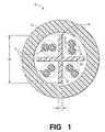
- the electrical cable 10 comprises a jacket 12, made of a suitable polymeric material, surrounding four pair of individually insulated conductors or conductive elements 14 separated by a flute or spacer element 16.
- the individually insulated conductor pairs typically comprise twisted pairs of copper wire 18 individually insulated with FEP or PFA insulation 22.
- the flute 16 is made of a suitable dielectric material such as FEP, ECTFE, PFA, PTFE or PVC.
- the dielectric jacket is made of, for example, low smoke polyvinyl chloride (LSPVC), ECTFE or other suitable material.
- the flute 16 has a plurality of webs or fins 24 arranged to maintain substantially constant spacing between the conductor pairs 14 along the length of the electrical cable 10.
- the flute 16 typically, when only two of four twisted pairs are active, alternating conductor pairs often are active to reduce crosstalk. In this manner, a certain degree of spacing for reducing crosstalk is inherent in the specific arrangement of the electrical cable.
- the flute 16 has an overall width, defined herein for purposes of discussion herein as the distance from the tip of one web to the tip of an opposing web.
- the overall width of the flute 16 is shown generally as W.
- the webs have a thickness, defined herein for purposes of discussion herein as the distance from the surface of one side of the web through the web to the surface of the opposing side of the web. The thickness of the web is shown generally as T.
- FEP flutes with an average web thickness greater than approximately 14 mils typically have a sufficient amount of FEP to cause a breach of the dielectric jacket during burn tests by pooling and combining with pooled FEP from the conductive element FEP insulation 22.
- breaching the dielectric jacket exposes a greater amount of PVC during the burn test, which exposure often causes smoke failures for the cable during UL910 or NFPA 90A burn tests.
- Embodiments of the invention are based on the realization that flutes and other spacer elements are effectively increased in size for improving crosstalk without correspondingly increasing the volume or amount of flute material in the electrical cabling, which additional volume often contributes adversely to failed burn test characteristics.
- embodiments of the invention are based on flutes that effectively are larger, wider and thicker, but generally are less dense (more porous) that conventional flutes.
- a foamed, perfluoronated resin flute or cross-web is used in electrical cables, for example, the cable 10 shown in Fig. 1.
- the foamed, perfluoronated resin flute which typically comprises gas-filled cells throughout its mass, has a density less than conventional, non-foamed flutes.
- the foamed flute is made, for example, by a conventional process such as continuous extrusion or other suitable process.
- foamed flutes are made by feeding a thermoplastic resin or other suitable material into an extruder and, through the shearing action of one or more extruder screws, melting the resin continuously in the barrel of the extruder.
- a chemical nucleating agent such as boron nitrate or other suitable material is dispersed throughout the particulate resin in powder form before the resin is fed to the extruder.
- the extruder screw then mixes and disperses the nucleating agent uniformly in the molten resin.
- a gas such as nitrogen or carbon dioxide is injected into the molten resin.
- the molten mixture is forced through a die, then undergoes decompression to atmospheric pressure so that the gas expands out from the nucleating agent within the body of material as bubbles (cells) and a foamed shape is produced.
- the size of the cells within the foamed flute varies, for example, from relatively large cells having diameters greater than approximately 10 microns ( ⁇ m) to microcells having diameters less than approximately 10 ⁇ m.
- a melt fractured, perfluoronated resin flute or cross-web is used in electrical cables, for example, the cable 10 shown in Fig. 1. More specifically, alternative embodiments of the invention include a flute or cross-web made of a perfluoronated resin such as FEP, and includes melt fracture characteristics on its surface.
- Flutes made of FEP and/or other polymer materials are manufactured, for example, by continuous extrusion processes, in which the polymer material is pumped, for example, with an extrusion screw, through an extrusion die that shapes the polymer as desired. As the polymer is pumped through the extrusion die, the polymer undergoes a wide range of shear rates. As long as the extrusion rate remains below a value known as the critical shear rate, the extruded material will not be subjected to shear rates that cause a phenomenon know as melt fracture.
- melt fracture is a general term used by the polymer processing industry to describe a variety of extrudate irregularities during extrusion of molten polymers through extrusion dies.
- melt fracture occurs when the extrusion rate exceeds the critical shear rate.
- the surface of the extruded material generally is relatively smooth and glossy.
- the extruded material begins to exhibit loss of surface gloss (known as surface melt fracture).
- the loss of gloss is due to fine scale roughness of the surface of the extruded material, which roughness is observable under a microscope at moderate magnification (20-40x).
- the roughness is the result of surface irregularities in the form of closely spaced circumferential ridges along the surface of the extruded material. In a more severe form, the roughness resembles'what is generally known as "sharkskin". Moreover, as the extrusion rate increases even further, the extruded material exhibits additional irregularities not limited to the surface (known as gross melt fracture).
- the extrusion rate is a function of several process parameters, including, for example, line speed, production output, extruder temperatures and tooling design such as the shape of the extrusion die. Accordingly, varying one or more of these parameters determines whether the extrusion rate approaches and/or exceeds the critical shear rate for the given extruded material. Thus, the extent of melt fracture on the extruded material is affected by the various processing parameters.
- melt fracture of extruded materials is undesirable, for example, for aesthetic purposes and other reasons.
- continuous extrusion processing parameters conventionally are set to increase or even maximize production (that is, extrusion rate) without sacrificing the smoothness of the extruded material (that is, reduce or minimize melt fracture).
- a number of U.S. Patents disclose methods for reducing and/or eliminating melt fracture within continuous extrusion processes. See, for example, U.S. Patent Nos. 4,522,776; 5,204,032 and 4,321,229.
- a flute or cross-web used in electrical cables for example, the cable 10 shown in Fig. 1, is made of a perfluoronated resin such as FEP or perfluoroalkoxy polymers (PFA), and includes melt fracture characteristics on its surface.
- a perfluoronated resin such as FEP or perfluoroalkoxy polymers (PFA)
- PFA perfluoroalkoxy polymers
- the roughened flute surface effectively increases the size of the flute webs (and thus works to increase the spacing between conductive elements in the electrical cable) without actually increasing the size and amount of flute material used in making the flute.
- crosstalk is reduced by the increased spacing between the conductor pairs.
- the method for making such an apparatus according to embodiments of the invention includes extruding the perfluoronated resin flute at an extrusion rate greater than the critical shear rate for the extruded material.
- Fig. 2 shown is a photograph of a cross-section of a conventional flute in a cross-section taken at approximately 38x magnification.
- the conventional flute is a relatively solid material with relatively smooth surfaces.
- the flute has a plurality of ribs or cross-webs used for maintaining separation of the conductive elements such as twisted pairs, as discussed hereinabove.
- the surface of the flute is relatively smooth and glossy. In this manner, the finish is aesthetically appealing.
- the overall width of the flute shown is approximately 150 mils ( ⁇ x, which extends almost to the tips of the webs, is 100.0 mils). Again, the width is defined herein as the distance from the tip of one web to the tip of an opposing web.
- the average thickness of the webs shown is approximately 13-14 mils ( ⁇ y is 13.3 mils).
- the thickness is defined as the distance from the surface of one side of the web through the web to the surface of the opposing side of the web. More specifically, for purposes of discussion herein, the measured thickness of the webs is taken at locations approximately 50 mils from the center of the flute. Such locations are marked in Fig. 2 by a vertical line. Accordingly, the distance ⁇ y at either of the vertical lines is approximately 13.3 mils.
- the weight per unit length of the conventional flute shown is approximately 5.07 grams per meter (g/m).
- a photograph of a foamed flute according to embodiments of the invention is shown.
- the photograph of the foamed flute, shown in cross-section, was taken at approximately 38x magnification.
- the foamed flute which has gas-filled cells throughout its mass, appears thicker yet less dense than the conventional flute shown in Fig. 2.
- the surface of the foamed flute does not look as smooth and glossy as that of the conventional flute of Fig. 2, although such surface roughness is not as significant as, for example, the surface roughness of a melt fracture flute (shown in Fig. 4 and discussed hereinbelow).
- Foamed flutes according to embodiments of the invention have a weight per unit length less than approximately 6.0 grams per meter (g/m).
- the foamed flute of Fig. 3 has a weight per unit length of approximately 3.6 grams per meter (g/m). This compares advantageously with the 5.07 grams per meter of the conventional flute shown in Fig. 2 and described hereinabove.
- foamed flutes made by continuous extrusion processes are made similar to conventionally continuous molded flutes except for the addition of the nucleating agent and its associated processing.
- foamed flutes according to embodiments of the invention have an average web thickness of approximately 10-30 mils.
- the overall width of foamed flutes according to embodiments of the invention is approximately 140-150 mils, which compares similarly with an overall width of approximately 150 mils for the conventional flute of Fig. 2.
- the foamed flute of Fig. 3 has larger (thicker) webs than a conventional flute and thus improves crosstalk of, for example, conductive elements positioned between adjacent webs, by increasing the spacing between twisted pairs.
- the foamed flute has a weight per unit length similar to or even less than that of the conventional flute.
- the foamed flute according to embodiments of the invention does not provide additional FEP to an electrical cable.
- Fig. 4 a photograph of a melt fractured flute according to alternative embodiments of the invention is shown.
- the melt fractured flute shown in Fig. 4 has a weight per unit length similar to or even less than that of the conventional flute shown in Fig. 2, since the process parameters used to produce the two flutes were similar except those process parameters used to increase the extrusion rate above the critical shear rate in producing melt fractured flute of Fig. 4.
- melt fractured flute is characterized by a relatively rough surface along the webs.
- the average thickness of the webs at least for purposes of separating conductor elements within an electrical cable, effectively has been increased.
- the effective thickness of the webs shown, on average is approximately 20 mils.
- its weight per unit length is approximately the same or even less than that of the conventional flute shown in Fig. 2.
- the overall width of the melt fractured flute shown in Fig. 4 is approximately 145 mils and the weight per unit volume of the melt fractured flute shown in Fig. 4 is approximately 4.918 grams per meter (g/m).
- Such properties compare with the conventional flute of Fig. 2, wherein the overall width of is approximately 150 mils and the weight per unit volume is approximately 5.07 grams per meter (g/m).
- the method 30 includes a first step 32 of providing the paired conductive elements 14, for example, four twisted pairs of copper wire individually insulated with FEP or other suitable polymer.
- the next step 34 is to form the flute 16.
- the flute 16 is made of FEP or other suitable perfluoronated resin such as PFA.
- the step 34 forms a foamed flute, thus effectively increasing the width of the flute 16 and the thickness of the webs of the flute 16 is without increasing the amount of FEP used in making the flute 16.
- the flute 16 is formed so that melt fracture of the flute 16 occurs, thus effectively increasing the thickness of the webs of the flute without increasing the amount of FEP in the flute 16.
- the next step 36 is to configure the flute 16 and the conductor pairs 14 such that the flute 16 provides spacing between the conductor pairs, for example, as shown in Fig. 1.
- the flute 16 and the conductor pairs 14 are payed out together, for example, in a conventional manner, such that the conductor pairs 14 generally occupy the regions of the flute 16 on either side of the individual webs 24.
- the next step 38 is to form the dielectric jacket 12 around the conductor pairs 14 and the flute 16, for example, as shown in Fig. 1.
- the dielectric jacket 12 is formed, for example, by extruding a suitable polymeric material around the conductor pairs 14 and the flute 16, for example, using a conventional continuous extrusion process.
Abstract
Description
- The invention relates to electrical cabling. More particularly, the invention relates to electrical cabling having improved flame retardancy and reduced crosstalk.
- Improving the transmission characteristics of electrical communication cables including local area network (LAN) cables is an existing challenge among those in the communications industry. One aspect of improving transmission characteristics is reducing crosstalk. Conventionally, within electrical cables that contain a plurality of twisted pairs of individually insulated conductors such as copper wires, many configurations and techniques have been implemented to reduce crosstalk between electrically conducting pairs by separating parallel and adjacent transmission lines.
- For example, flutes or cross-webs or other suitable spacer elements have been included in the electrical cable to maintain sufficient spacing between the conducting pairs and thus reduce crosstalk therebetween. See, U.S. Patent Nos. 4,920,234 and 5,149,915. Because typical communications industry electrical cables include four twisted pair, many flutes are configured as centrally-located spacer elements with one or more cross-web sections around which the twisted pairs are arranged. See, for example, U.S. Patent Nos. 5,132,488; 5,519,173; 5,574,250; and 5,789,711.
- Another concern for electrical cabling, particularly plenum rated cabling and other cabling used in various indoor applications, is maintaining sufficient flame retardancy and low smoke characteristics. Electrical communication cables having insulation materials formed from fluoropolymers typically must pass standardized fire tests, for example, the Underwriter's Laboratory Standard 910 test (the Steiner Tunnel test), which qualifies these cables for use in a plenum space inside buildings.
- Unfortunately, improving crosstalk within electrical cabling by increasing the spacing between the twisted pairs using larger and/or thicker flutes or cross-webs often reduces flame retardancy characteristics of the cable. For example, when spacer elements are made of, for example, fluorinated ethylene-propylene (FEP), and have an average web thickness greater than approximately 15 mils (0.381 millimeters), the FEP from the spacer element adds to the existing FEP insulation of the copper wires and, during burn tests, increases potential pooling of FEP within the cable's dielectric jacket surrounding the conductive elements. The dielectric jacket typically is made of poly(vinyl chloride) (PVC) or other suitable material. During burn tests, the increased FEP pooling caused by the FEP spacer element often is sufficient to cause the jacket to breach, which tends to expose more PVC and often causes the cable to fail the smoke portion of the burn test.
- Accordingly, what is needed is a spacer element for electrical cabling that improves crosstalk without reducing the overall flame and smoke retardancy characteristics of the cable needed for passing burn test requirements.
- The invention is as defined by the claims. Embodiments of the invention include an electrical cable flute and fluted electrical cable. The electrical cable flute is made of a perfluoronated resin such as fluorinated ethylene-propylene (FEP) or perfluoroalkoxy polymers (PFA), and is configured to have a plurality of webs arranged in such a way that the webs separate various paired conductive elements within a fluted electrical cable. The thickness of the individual webs is, for example, approximately 10 mils (0.254 millimeters) to approximately 30 mils (0.762 millimeters), the overall width of the flute as measured from the tip of one web to the tip of an opposing web is, for example, approximately 120 mils (3.048 millimeters) to approximately 170 mils (4.318 millimeters), and the weight per unit length of the flute is, for example, less than approximately 6.0 grams per meter (g/m). According to an embodiment of the invention, the flute is a foamed flute. According to alternative embodiments of the invention, the flute is a melt fractured flute.
- Embodiments of the invention also include a fluted electrical cable having a plurality of paired conductors, a dielectric jacket formed around the paired conductors, and an inventive flute configured to separate the paired conductors within the dielectric jacket. According to embodiments of the invention, the flute is made of a perfluoronated resin such as FEP and is configured with webs arranged to separate the conductive elements within the cable. The thickness of the individual webs is, for example, approximately 10 mils to approximately 30 mils, the overall width of the flute from the tip of one web to the tip of an opposing web is, for example, approximately 120 mils to approximately 170 mils, and the weight per unit length of the flute is, for example, less than approximately 6.0 grams per meter (g/m). The flute is a foamed flute or, alternatively, a melt fractured flute.
- Embodiments of the invention also include a method for making a flute used, for example, in a fluted electrical cable. The method includes extruding a perfluoronated resin such as FEP from an extruder in such a way that the flute has webs, for example, approximately 10-30 mils thick, an overall width from the tip of one web to the tip of an opposing web of, for example, approximately 120 mils to approximately 170 mils, and a weight per unit length of less than, for example, approximately 6.0 grams per meter (g/m). The method also includes extruding the flute in such a way that the flute is configured to separate conductor elements within the electrical cable. In one embodiment, the method includes forming a foamed flute. Alternatively, the method includes forming a melt fractured flute, for example, by extruding the perfluoronated resin at an extrusion rate that exceeds the critical shear rate for such material.
- Embodiments of the invention also include a method for making an electrical cable having a plurality of paired conductors separated by an inventive flute, and a dielectric jacket formed around the paired conductors and the inventive flute. The method includes providing the paired conductors, forming the inventive flute between the plurality of paired conductors, and forming a dielectric jacket around the paired conductors and the flute. The flute is a foamed flute made, for example, by extrusion molding a perfluoronated resin such as FEP. Alternatively, the method includes forming a melt fractured flute, for example, by extruding the perfluoronated resin at an extrusion rate that exceeds the critical shear rate for such material.
- In the drawings:
- Fig. 1 is a cross-sectional view of a conventional electrical cable capable of employing embodiments of the invention;
- Fig. 2 is a photograph of a conventional flute in a cross-section taken at approximately 38x magnification;
- Fig. 3 is a photograph of a flute according to embodiments of the invention in a cross-section taken at approximately 38x magnification;
- Fig. 4 is a photograph of a flute according to alternative embodiments of the invention in a cross-section taken at approximately 38x magnification; and
- Fig. 5 is a simplified block diagram of a method for making a flute and a fluted cable according to embodiments of the invention.
-
- In the following description, similar components are referred to by the same reference numeral to enhance the understanding of the invention through the description of the drawings.
- Although specific features, configurations and arrangements are discussed hereinbelow, it should be understood that such is done for illustrative purposes only. A person skilled in the relevant art will recognize that other steps, configurations and arrangements are useful without departing from the spirit and scope of the invention.
- Electrical communication cables typically comprise a plurality of paired conductive elements such as twisted pairs of copper wire having insulation for the individual wires forming the pairs, and a protective dielectric jacket surrounding the group of conductive pairs. Many electrical cables also use a flute or cross-web or other spacer element to provide spacing between the conductive element pairs within the jacket. In this manner, crosstalk is reduced by separating parallel and adjacent transmission lines in an electrical cable.
- Electrical cables for use, for example, as plenum cables, and for other indoor applications typically have flame retardancy and low smoke requirements, as set by an authority such as the Underwriters Laboratory Incorporated or Intertek Testing Services. For example, cables passing the UL-910 test (the Steiner Tunnel test) are considered plenum rated. Because of the UL-910 bum test requirements, many plenum cables use materials that are relatively flame retardant and that produce relatively low smoke. For example, such materials are used for individually insulating the copper wires or other conductive elements that form the twisted pairs. Also, such materials are used for spacer elements. Such materials include fluoropolymers such as fluorinated ethylene-propylene (FEP), ethylenechlorotrifluoroethylene (ECTFE), perfluoroalkoxy polymers (PFA), polytetrafluoroethylene (PTFE) and poly(vinyl chloride) (PVC).
- Referring now to Fig. 1, shown is an
electrical cable 10 having a conventional arrangement, as just discussed. Theelectrical cable 10 comprises ajacket 12, made of a suitable polymeric material, surrounding four pair of individually insulated conductors orconductive elements 14 separated by a flute orspacer element 16. The individually insulated conductor pairs typically comprise twisted pairs ofcopper wire 18 individually insulated with FEP orPFA insulation 22. Theflute 16 is made of a suitable dielectric material such as FEP, ECTFE, PFA, PTFE or PVC. The dielectric jacket is made of, for example, low smoke polyvinyl chloride (LSPVC), ECTFE or other suitable material. - To reduce crosstalk within the
cable 10, theflute 16 has a plurality of webs orfins 24 arranged to maintain substantially constant spacing between the conductor pairs 14 along the length of theelectrical cable 10. Typically, when only two of four twisted pairs are active, alternating conductor pairs often are active to reduce crosstalk. In this manner, a certain degree of spacing for reducing crosstalk is inherent in the specific arrangement of the electrical cable. - Conventionally, the
flute 16 has an overall width, defined herein for purposes of discussion herein as the distance from the tip of one web to the tip of an opposing web. The overall width of theflute 16 is shown generally as W. Also, the webs have a thickness, defined herein for purposes of discussion herein as the distance from the surface of one side of the web through the web to the surface of the opposing side of the web. The thickness of the web is shown generally as T. - Although FEP is advantageous for purposes of reducing crosstalk and for having advantageous bum test characteristics, having too much FEP within the
cable 10 is disadvantageous. For example, according to embodiments of the invention, FEP flutes with an average web thickness greater than approximately 14 mils (that is, 0.015 inches or 0.381 millimeters) typically have a sufficient amount of FEP to cause a breach of the dielectric jacket during burn tests by pooling and combining with pooled FEP from the conductiveelement FEP insulation 22. As discussed hereinabove, breaching the dielectric jacket exposes a greater amount of PVC during the burn test, which exposure often causes smoke failures for the cable during UL910 or NFPA 90A burn tests. - Embodiments of the invention are based on the realization that flutes and other spacer elements are effectively increased in size for improving crosstalk without correspondingly increasing the volume or amount of flute material in the electrical cabling, which additional volume often contributes adversely to failed burn test characteristics. Thus, embodiments of the invention are based on flutes that effectively are larger, wider and thicker, but generally are less dense (more porous) that conventional flutes.
- According to embodiments of the invention, a foamed, perfluoronated resin flute or cross-web is used in electrical cables, for example, the
cable 10 shown in Fig. 1. The foamed, perfluoronated resin flute, which typically comprises gas-filled cells throughout its mass, has a density less than conventional, non-foamed flutes. Thus, according to embodiments of the invention, it is possible for electrical cables to use thicker but less dense, foamed flutes, which do not disadvantageously increase the amount of FEP or other perfluoronated resin within the electrical cable. Accordingly, the increased size of the foamed flute improves crosstalk spacing without adding additional perfluoronated resin in the cable that might otherwise contribute to increased smoking during burn tests. - The foamed flute is made, for example, by a conventional process such as continuous extrusion or other suitable process. In conventional continuous extrusion processes, foamed flutes are made by feeding a thermoplastic resin or other suitable material into an extruder and, through the shearing action of one or more extruder screws, melting the resin continuously in the barrel of the extruder. A chemical nucleating agent such as boron nitrate or other suitable material is dispersed throughout the particulate resin in powder form before the resin is fed to the extruder. The extruder screw then mixes and disperses the nucleating agent uniformly in the molten resin. In an intermediate or mixing section of the extruder, a gas such as nitrogen or carbon dioxide is injected into the molten resin. The molten mixture is forced through a die, then undergoes decompression to atmospheric pressure so that the gas expands out from the nucleating agent within the body of material as bubbles (cells) and a foamed shape is produced. The size of the cells within the foamed flute varies, for example, from relatively large cells having diameters greater than approximately 10 microns (µm) to microcells having diameters less than approximately 10 µm.
- According to alternative embodiments of the invention, a melt fractured, perfluoronated resin flute or cross-web is used in electrical cables, for example, the
cable 10 shown in Fig. 1. More specifically, alternative embodiments of the invention include a flute or cross-web made of a perfluoronated resin such as FEP, and includes melt fracture characteristics on its surface. - Flutes made of FEP and/or other polymer materials are manufactured, for example, by continuous extrusion processes, in which the polymer material is pumped, for example, with an extrusion screw, through an extrusion die that shapes the polymer as desired. As the polymer is pumped through the extrusion die, the polymer undergoes a wide range of shear rates. As long as the extrusion rate remains below a value known as the critical shear rate, the extruded material will not be subjected to shear rates that cause a phenomenon know as melt fracture.
- Melt fracture is a general term used by the polymer processing industry to describe a variety of extrudate irregularities during extrusion of molten polymers through extrusion dies. As discussed, melt fracture occurs when the extrusion rate exceeds the critical shear rate. As long as the extrusion rate remains below the critical shear rate, the surface of the extruded material generally is relatively smooth and glossy. However, at extrusion rates above the critical shear rate, the extruded material begins to exhibit loss of surface gloss (known as surface melt fracture). The loss of gloss is due to fine scale roughness of the surface of the extruded material, which roughness is observable under a microscope at moderate magnification (20-40x). The roughness is the result of surface irregularities in the form of closely spaced circumferential ridges along the surface of the extruded material. In a more severe form, the roughness resembles'what is generally known as "sharkskin". Moreover, as the extrusion rate increases even further, the extruded material exhibits additional irregularities not limited to the surface (known as gross melt fracture).
- In extrusion processes, the extrusion rate is a function of several process parameters, including, for example, line speed, production output, extruder temperatures and tooling design such as the shape of the extrusion die. Accordingly, varying one or more of these parameters determines whether the extrusion rate approaches and/or exceeds the critical shear rate for the given extruded material. Thus, the extent of melt fracture on the extruded material is affected by the various processing parameters.
- In conventional continuous extrusion processes, melt fracture of extruded materials is undesirable, for example, for aesthetic purposes and other reasons. Thus, continuous extrusion processing parameters conventionally are set to increase or even maximize production (that is, extrusion rate) without sacrificing the smoothness of the extruded material (that is, reduce or minimize melt fracture). For example, a number of U.S. Patents disclose methods for reducing and/or eliminating melt fracture within continuous extrusion processes. See, for example, U.S. Patent Nos. 4,522,776; 5,204,032 and 4,321,229.
- However, according to alternative embodiments of the invention, a flute or cross-web used in electrical cables, for example, the
cable 10 shown in Fig. 1, is made of a perfluoronated resin such as FEP or perfluoroalkoxy polymers (PFA), and includes melt fracture characteristics on its surface. In this manner, the roughened flute surface effectively increases the size of the flute webs (and thus works to increase the spacing between conductive elements in the electrical cable) without actually increasing the size and amount of flute material used in making the flute. In this manner, crosstalk is reduced by the increased spacing between the conductor pairs. The method for making such an apparatus according to embodiments of the invention includes extruding the perfluoronated resin flute at an extrusion rate greater than the critical shear rate for the extruded material. - Referring now to Fig. 2, shown is a photograph of a cross-section of a conventional flute in a cross-section taken at approximately 38x magnification. As shown, the conventional flute is a relatively solid material with relatively smooth surfaces. The flute has a plurality of ribs or cross-webs used for maintaining separation of the conductive elements such as twisted pairs, as discussed hereinabove. As can be seen from the photograph, the surface of the flute is relatively smooth and glossy. In this manner, the finish is aesthetically appealing. The overall width of the flute shown is approximately 150 mils (Δx, which extends almost to the tips of the webs, is 100.0 mils). Again, the width is defined herein as the distance from the tip of one web to the tip of an opposing web.
- The average thickness of the webs shown is approximately 13-14 mils (▵y is 13.3 mils). As discussed previously herein, the thickness is defined as the distance from the surface of one side of the web through the web to the surface of the opposing side of the web. More specifically, for purposes of discussion herein, the measured thickness of the webs is taken at locations approximately 50 mils from the center of the flute. Such locations are marked in Fig. 2 by a vertical line. Accordingly, the distance Δy at either of the vertical lines is approximately 13.3 mils. The weight per unit length of the conventional flute shown is approximately 5.07 grams per meter (g/m).
- Referring now to Fig. 3, a photograph of a foamed flute according to embodiments of the invention is shown. The photograph of the foamed flute, shown in cross-section, was taken at approximately 38x magnification. As can be seen, the foamed flute, which has gas-filled cells throughout its mass, appears thicker yet less dense than the conventional flute shown in Fig. 2. Also, the surface of the foamed flute does not look as smooth and glossy as that of the conventional flute of Fig. 2, although such surface roughness is not as significant as, for example, the surface roughness of a melt fracture flute (shown in Fig. 4 and discussed hereinbelow).
- Foamed flutes according to embodiments of the invention have a weight per unit length less than approximately 6.0 grams per meter (g/m). For example, the foamed flute of Fig. 3 has a weight per unit length of approximately 3.6 grams per meter (g/m). This compares advantageously with the 5.07 grams per meter of the conventional flute shown in Fig. 2 and described hereinabove. As discussed hereinabove, foamed flutes made by continuous extrusion processes are made similar to conventionally continuous molded flutes except for the addition of the nucleating agent and its associated processing.
- Even thought the weight per unit length of the foamed flute shown in Fig 3 is less than that of the conventional flute shown in Fig. 2, the thickness of the webs of the foamed flute is approximately 20 mils (Δy is 19.9 mils), which is approximately 33% thicker than the web thickness of the conventional flute of Fig. 2. In general, foamed flutes according to embodiments of the invention have an average web thickness of approximately 10-30 mils. The overall width of foamed flutes according to embodiments of the invention is approximately 140-150 mils, which compares similarly with an overall width of approximately 150 mils for the conventional flute of Fig. 2.
- Accordingly, the foamed flute of Fig. 3 has larger (thicker) webs than a conventional flute and thus improves crosstalk of, for example, conductive elements positioned between adjacent webs, by increasing the spacing between twisted pairs. However, as discussed, even though the volume of the foamed flute is greater than that of the conventional flute of Fig. 2, the foamed flute has a weight per unit length similar to or even less than that of the conventional flute. Thus, the foamed flute according to embodiments of the invention does not provide additional FEP to an electrical cable.
- Referring now to Fig. 4, a photograph of a melt fractured flute according to alternative embodiments of the invention is shown. The photograph of the melt fractured flute, shown in cross-section, was taken at approximately 38x magnification. It should be noted that the melt fractured flute shown in Fig. 4 has a weight per unit length similar to or even less than that of the conventional flute shown in Fig. 2, since the process parameters used to produce the two flutes were similar except those process parameters used to increase the extrusion rate above the critical shear rate in producing melt fractured flute of Fig. 4.
- Unlike the relatively smooth and glossy surface of the conventional flute shown in Fig. 2, the melt fractured flute according to alternative embodiments of the invention is characterized by a relatively rough surface along the webs.
- Because of the roughened surface, the average thickness of the webs, at least for purposes of separating conductor elements within an electrical cable, effectively has been increased. For example, in Fig. 4, the effective thickness of the webs shown, on average, is approximately 20 mils. However, despite the increased spacing created by the melt fracture flute, its weight per unit length is approximately the same or even less than that of the conventional flute shown in Fig. 2. For example, the overall width of the melt fractured flute shown in Fig. 4 is approximately 145 mils and the weight per unit volume of the melt fractured flute shown in Fig. 4 is approximately 4.918 grams per meter (g/m). Such properties compare with the conventional flute of Fig. 2, wherein the overall width of is approximately 150 mils and the weight per unit volume is approximately 5.07 grams per meter (g/m).
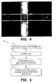
- Referring now to Fig. 5, shown is a simplified block diagram of a
method 30 for making a flute and a fluted cable according to embodiments of the invention. Themethod 30 includes afirst step 32 of providing the pairedconductive elements 14, for example, four twisted pairs of copper wire individually insulated with FEP or other suitable polymer. - The
next step 34 is to form theflute 16. According to embodiments of the invention, theflute 16 is made of FEP or other suitable perfluoronated resin such as PFA. As discussed hereinabove, according to embodiments of the invention, thestep 34 forms a foamed flute, thus effectively increasing the width of theflute 16 and the thickness of the webs of theflute 16 is without increasing the amount of FEP used in making theflute 16. Alternatively, theflute 16 is formed so that melt fracture of theflute 16 occurs, thus effectively increasing the thickness of the webs of the flute without increasing the amount of FEP in theflute 16. - The
next step 36 is to configure theflute 16 and the conductor pairs 14 such that theflute 16 provides spacing between the conductor pairs, for example, as shown in Fig. 1. For example, once theflute 16 has been formed, theflute 16 and the conductor pairs 14 are payed out together, for example, in a conventional manner, such that the conductor pairs 14 generally occupy the regions of theflute 16 on either side of theindividual webs 24. - The
next step 38 is to form thedielectric jacket 12 around the conductor pairs 14 and theflute 16, for example, as shown in Fig. 1. Thedielectric jacket 12 is formed, for example, by extruding a suitable polymeric material around the conductor pairs 14 and theflute 16, for example, using a conventional continuous extrusion process. - It will be apparent to those skilled in the art that many changes and substitutions can be made to the embodiments of the electrical cabling flutes and fluted electrical cabling apparatus and methods herein described without departing from the spirit and scope of the invention as defined by the appended claims and their full scope of equivalents.
Claims (9)
- An electrical cable (10), comprising:CHARACTERIZED IN THATa plurality of paired conductive elements (14);a dielectric jacket (12) formed around the plurality of paired conductive elements; anda flute (16) configured to separate at least one pair of the paired conductive elements from at least one other pair of the paired conductive elements within the dielectric jacket,wherein the flute is made of a perfluoronated resin,the flute has a plurality of webs (24) having a thickness (T) within the range from approximately 10 mils to approximately 30 mils,the width (W) of the flute from the tip of one web to the tip of an opposing web is within the range from approximately 120 mils to approximately 170 mils, andthe flute is less than approximately 6.0 grams per meter (g/m).
- The cable as recited in claim 1, wherein the flute further comprises a foamed perfluoronated resin or a melt fractured perfluoronated resin.
- The cable as recited in claim 1, wherein the flute further comprises a material including one or more materials selected from the group consisting of fluorinated ethylene-propylene (FEP), ethylenechlorotrifluoroethylene (ECTFE), perfluoroalkoxy polymers (PFA), polytetrafluoroethylene (PTFE) and poly(vinyl chloride) (PVC).
- The cable as recited in claim 1, wherein the at least one pair of conductive elements further comprises four pair of individually insulated conductive elements and wherein the flute separates the four pair of individually insulated conductive elements in such a way that the pairs of individually insulated conductive elements generally occupy a different quadrant within the electrical cable.
- A flute for use in a fluted electrical cable, the fluted electrical cable having a plurality of paired electrical conductive elements and a dielectric jacket formed therearound, said flute comprising:a plurality of webs arranged with respect to one another in such a way that the webs separate at least one pair of the paired conductive elements from at least one other pair of the paired conductive elements within the dielectric jacket,wherein the thickness of individual webs is within the range from approximately 10 mils to approximately 30 mils,wherein the width of the flute from the tip of one web to the tip of an opposing web is within the range from approximately 120 mils to approximately 170 mils,wherein the flute is less than approximately 6.0 grams per meter (g/m), andwherein the flute is made of a perfluoronated resin.
- The flute as recited in claim 5, wherein the flute further comprises a foamed perfluoronated resin or a melt fractured perfluoronated resin.
- The flute as recited in claim 5, wherein the flute further comprises a material including one or more materials selected from the group consisting of fluorinated ethylene-propylene (FEP), ethylenechlorotrifluoroethylene (ECTFE), perfluoroalkoxy polymers (PFA), polytetrafluoroethylene (PTFE) and poly(vinyl chloride) (PVC).
- A method for making a flute for use in a fluted electrical cable, said method comprising the steps of:extruding the flute from an extruder in such a way that the flute has a plurality of webs with a thickness within the range from approximately 10 mils to approximately 30 mils, the flute has a width from the tip of one web to the tip of an opposing web within the range from approximately 120 mils to approximately 170 mils, and the flute has a weight per unit length of less than approximately 6.0 grams per meter (g/m),wherein the flute is made of a perfluoronated resin, andwherein the flute is configured to separate paired conductive elements within the electrical cable.
- The method as recited in claim 8, wherein the extruding step is performed in such a way that the extrusion rate exceeds the critical shear rate for the flute.
Applications Claiming Priority (2)
| Application Number | Priority Date | Filing Date | Title |
|---|---|---|---|
| US49291400A | 2000-01-13 | 2000-01-13 | |
| US492914 | 2000-01-13 |
Publications (2)
| Publication Number | Publication Date |
|---|---|
| EP1117103A2 true EP1117103A2 (en) | 2001-07-18 |
| EP1117103A3 EP1117103A3 (en) | 2002-11-06 |
Family
ID=23958116
Family Applications (1)
| Application Number | Title | Priority Date | Filing Date |
|---|---|---|---|
| EP01300260A Withdrawn EP1117103A3 (en) | 2000-01-13 | 2001-01-12 | Electrical cable having improved flame retardancy and reduced crosstalk and method for making |
Country Status (2)
| Country | Link |
|---|---|
| EP (1) | EP1117103A3 (en) |
| JP (1) | JP2001273822A (en) |
Cited By (4)
| Publication number | Priority date | Publication date | Assignee | Title |
|---|---|---|---|---|
| EP2065156A1 (en) * | 2007-11-29 | 2009-06-03 | Nexans | Method for producing a moulded product from polytetrafluorothylene foam |
| EP1833061A3 (en) * | 2006-03-06 | 2011-07-20 | Belden Technologies, Inc. | Web for separating conductors in a communication cable |
| US8729394B2 (en) | 1997-04-22 | 2014-05-20 | Belden Inc. | Enhanced data cable with cross-twist cabled core profile |
| WO2015197033A1 (en) * | 2014-06-27 | 2015-12-30 | 罗广荣 | Method and device for avoiding harmonic waves |
Families Citing this family (4)
| Publication number | Priority date | Publication date | Assignee | Title |
|---|---|---|---|---|
| US7838773B2 (en) * | 2004-11-15 | 2010-11-23 | Belden Cdt (Canada) Inc. | High performance telecommunications cable |
| JP5068663B2 (en) * | 2004-12-16 | 2012-11-07 | ジェネラル・ケーブル・テクノロジーズ・コーポレーション | Electrical cable with filler elements with reduced crosstalk |
| KR100820496B1 (en) * | 2006-11-22 | 2008-04-08 | 엘에스전선 주식회사 | Communication cables for emi shielding |
| WO2017013765A1 (en) * | 2015-07-22 | 2017-01-26 | 日立金属株式会社 | Coaxial cable and medical cable |
Citations (2)
| Publication number | Priority date | Publication date | Assignee | Title |
|---|---|---|---|---|
| US5789711A (en) * | 1996-04-09 | 1998-08-04 | Belden Wire & Cable Company | High-performance data cable |
| US5952615A (en) * | 1995-09-15 | 1999-09-14 | Filotex | Multiple pair cable with individually shielded pairs that is easy to connect |
-
2001
- 2001-01-12 EP EP01300260A patent/EP1117103A3/en not_active Withdrawn
- 2001-01-15 JP JP2001006174A patent/JP2001273822A/en active Pending
Patent Citations (2)
| Publication number | Priority date | Publication date | Assignee | Title |
|---|---|---|---|---|
| US5952615A (en) * | 1995-09-15 | 1999-09-14 | Filotex | Multiple pair cable with individually shielded pairs that is easy to connect |
| US5789711A (en) * | 1996-04-09 | 1998-08-04 | Belden Wire & Cable Company | High-performance data cable |
Cited By (7)
| Publication number | Priority date | Publication date | Assignee | Title |
|---|---|---|---|---|
| US8729394B2 (en) | 1997-04-22 | 2014-05-20 | Belden Inc. | Enhanced data cable with cross-twist cabled core profile |
| EP1833061A3 (en) * | 2006-03-06 | 2011-07-20 | Belden Technologies, Inc. | Web for separating conductors in a communication cable |
| US8030571B2 (en) | 2006-03-06 | 2011-10-04 | Belden Inc. | Web for separating conductors in a communication cable |
| EP2065156A1 (en) * | 2007-11-29 | 2009-06-03 | Nexans | Method for producing a moulded product from polytetrafluorothylene foam |
| US7767725B2 (en) | 2007-11-29 | 2010-08-03 | Nexans | High processing temperature foaming polymer composition |
| US8013030B2 (en) | 2007-11-29 | 2011-09-06 | Nexans | Process for the production of a moulding composed of foamed polytetrafluoroethylene |
| WO2015197033A1 (en) * | 2014-06-27 | 2015-12-30 | 罗广荣 | Method and device for avoiding harmonic waves |
Also Published As
| Publication number | Publication date |
|---|---|
| JP2001273822A (en) | 2001-10-05 |
| EP1117103A3 (en) | 2002-11-06 |
Similar Documents
| Publication | Publication Date | Title |
|---|---|---|
| US5969295A (en) | Twisted pair communications cable | |
| US6770819B2 (en) | Communications cables with oppositely twinned and bunched insulated conductors | |
| US5814768A (en) | Twisted pairs communications cable | |
| JP5741457B2 (en) | Parallel foamed coaxial cable | |
| JP5975334B2 (en) | Foamed resin molded body, foamed insulated wire and cable, and method for producing foamed resin molded body | |
| US20040055777A1 (en) | Communication wire | |
| EP2065155B1 (en) | High processing temperature foaming polymer composition | |
| US6231919B1 (en) | Method of making conductor insulated with foamed fluoropolymer | |
| US6064008A (en) | Conductor insulated with foamed fluoropolymer using chemical blowing agent | |
| JP5187214B2 (en) | Foamed resin composition and electric wire / cable using the same | |
| JP3927243B2 (en) | Plenum cable | |
| US4716073A (en) | Thin wall high performance insulation on wire | |
| WO2006071905A1 (en) | Electrical power cable having expanded polymeric layers | |
| WO2008079264A2 (en) | Foamable fluoropolymer composition | |
| EP1117103A2 (en) | Electrical cable having improved flame retardancy and reduced crosstalk and method for making | |
| JP2001035270A (en) | Parallel coaxial cable with low skew and manufacture thereof | |
| KR20060094440A (en) | Insulating material composition for cable and a cable having insulating layer made therefrom | |
| JP2010215796A (en) | Foaming resin composition, method for producing the same and foam-insulated wire using the same | |
| JP2007188742A (en) | Foam insulated wire and its manufacturing method | |
| JP2001067944A (en) | Fluororesin-coated electric wire and manufacture of fluororesin-coated electric wire | |
| US20170011818A1 (en) | Foam insulated conductors | |
| JPWO2011004835A1 (en) | Foamed electric wire and transmission cable having the same | |
| CN1301842C (en) | Facility and method for manufacturing coaxial wire with foamed insulator | |
| JP2535898B2 (en) | Method for manufacturing foamed fluororesin insulated wire | |
| JP2861283B2 (en) | Foam plastic insulated wire |
Legal Events
| Date | Code | Title | Description |
|---|---|---|---|
| PUAI | Public reference made under article 153(3) epc to a published international application that has entered the european phase |
Free format text: ORIGINAL CODE: 0009012 |
|
| AK | Designated contracting states |
Kind code of ref document: A2 Designated state(s): AT BE CH CY DE DK ES FI FR GB GR IE IT LI LU MC NL PT SE TR |
|
| AX | Request for extension of the european patent |
Free format text: AL;LT;LV;MK;RO;SI |
|
| PUAL | Search report despatched |
Free format text: ORIGINAL CODE: 0009013 |
|
| AK | Designated contracting states |
Kind code of ref document: A3 Designated state(s): AT BE CH CY DE DK ES FI FR GB GR IE IT LI LU MC NL PT SE TR |
|
| AX | Request for extension of the european patent |
Free format text: AL;LT;LV;MK;RO;SI |
|
| AKX | Designation fees paid |
Designated state(s): DE FR GB |
|
| STAA | Information on the status of an ep patent application or granted ep patent |
Free format text: STATUS: THE APPLICATION IS DEEMED TO BE WITHDRAWN |
|
| 18D | Application deemed to be withdrawn |
Effective date: 20030507 |