EP1116169B1 - Improvements relating to pattern recognition - Google Patents
Improvements relating to pattern recognition Download PDFInfo
- Publication number
- EP1116169B1 EP1116169B1 EP98944093A EP98944093A EP1116169B1 EP 1116169 B1 EP1116169 B1 EP 1116169B1 EP 98944093 A EP98944093 A EP 98944093A EP 98944093 A EP98944093 A EP 98944093A EP 1116169 B1 EP1116169 B1 EP 1116169B1
- Authority
- EP
- European Patent Office
- Prior art keywords
- pattern
- scene
- light emitting
- detector
- array
- Prior art date
- Legal status (The legal status is an assumption and is not a legal conclusion. Google has not performed a legal analysis and makes no representation as to the accuracy of the status listed.)
- Expired - Lifetime
Links
Images


Classifications
-
- G—PHYSICS
- G02—OPTICS
- G02B—OPTICAL ELEMENTS, SYSTEMS OR APPARATUS
- G02B26/00—Optical devices or arrangements for the control of light using movable or deformable optical elements
- G02B26/08—Optical devices or arrangements for the control of light using movable or deformable optical elements for controlling the direction of light
- G02B26/0808—Optical devices or arrangements for the control of light using movable or deformable optical elements for controlling the direction of light by means of one or more diffracting elements
-
- G—PHYSICS
- G02—OPTICS
- G02B—OPTICAL ELEMENTS, SYSTEMS OR APPARATUS
- G02B26/00—Optical devices or arrangements for the control of light using movable or deformable optical elements
- G02B26/08—Optical devices or arrangements for the control of light using movable or deformable optical elements for controlling the direction of light
- G02B26/10—Scanning systems
- G02B26/106—Scanning systems having diffraction gratings as scanning elements, e.g. holographic scanners
-
- G—PHYSICS
- G06—COMPUTING; CALCULATING OR COUNTING
- G06V—IMAGE OR VIDEO RECOGNITION OR UNDERSTANDING
- G06V10/00—Arrangements for image or video recognition or understanding
- G06V10/88—Image or video recognition using optical means, e.g. reference filters, holographic masks, frequency domain filters or spatial domain filters
-
- G—PHYSICS
- G06—COMPUTING; CALCULATING OR COUNTING
- G06V—IMAGE OR VIDEO RECOGNITION OR UNDERSTANDING
- G06V2201/00—Indexing scheme relating to image or video recognition or understanding
- G06V2201/08—Detecting or categorising vehicles
Definitions
- This invention relates to improvements in methods and apparatus for pattern recognition, and in particular to an improved method and apparatus for detecting the presence of and/or location of a reference object in a scene. It also relates to other inventions.
- Pattern recognition has widely varying applications, for example in industry.
- An example of a situation where a pattern recognition scheme is required is the detection of the type and location of a car on a busy street.
- Other examples are industrial production lines, security systems, vehicle identification, finger print and face recognition, etc.
- Such a process is trivial for a human when provided with a chart identifying car types and a clear view of the street.
- automation of the process by providing a camera to view the scene and computer pattern recognition is a complex process, especially when the illumination is variable and/or the vehicle is partially obscured.
- One method for detecting the presence of a predetermined known object within an image of a scene is to look for the correlation between the object and scenery. This can be achieved using the object and image directly, but in many cases it is more efficient to process the data concerned in the Fourier Transform domain, i.e. by processing the spatial frequency components of object and image. Mathematically these processes are related through the "convolution theorem" [reference 1: J W Goodman].
- the reference object (we shall always refer to the reference as an object and the scenery as an image) may be that of a car set against a clear background, or a shape of a bottle on a filling line etc.
- the scenery might comprise a traffic queue or the filling line, respectively.
- FIG. 1 A typical optical Vander Lugt-type scheme is shown in Figure 1 of the accompanying drawings.
- the system comprises an optical camera 1 which capture an image of the input scene and drives a spatial light modulator (SLM) 2 to display a mask corresponding to the captured image.
- SLM spatial light modulator
- the word "mask” will be used to describe the pattern displayed on an SLM, which pattern may in general include amplitude and/or phase information.
- a coherent laser beam is passed through a suitable beam expander to produce a wide beam of coherent light which propagates through the SLM 2.
- the original Vander Lugt work employed fixed holograms rather than SLMs which were unavailable at that time.
- the output of the SLM 2 which is located in the front focal plane of lens propagates through lens and forms a Fourier Transform of the mask in the back focal plane of lens where it impinges on a second SLM 4.
- the mask formed by SLM 4 comprises the phase conjugate of the Fourier transform of the reference object.
- the light propagating through the second SLM, SLM 4 is Fourier Transformed by a second lens 5 in the back focal plane of lens 5 where it is captured by the output camera 6.
- SLM 4 Fourier Transformed by a second lens 5 in the back focal plane of lens 5 where it is captured by the output camera 6.
- lens 5 would ideally perform an inverse Fourier transform but this difference is of no practical importance
- a sharp bright peak is produced in the pattern in the back focal plane of lens 5.
- the position of this peak is determined by the position of the reference object in the scene image.
- a large peak at the origin in the focal plane is also usually observed due to the DC spatial frequency component of the combined Fourier transform patterns of the scene and reference (i.e. overall intensity) and/or leakage of unmodulated light through the interpixel gaps of the SLM's.
- An object of the present invention is to ameliorate some of the problems present in the prior art pattern recognition schemes.
- the invention is defined in appended apparatus claim 1 and method claim 27.
- Figure 15 (as well as the list of terms of Appendix 1) which sets out certain nomenclature which will be adopted.
- Images are real things, scene image and reference image (which may be not provided in the system).
- Patterns are the Fourier transform (or Fourier-like transform), e.g. scene pattern and reference pattern. The multiplication of the image pattern and a reference pattern is termed the "combined pattern”.
- the reference pattern may be a synthetic discriminant function.
- the optical output means may comprise a spatial light modulator adapted to produce a mask dependent upon the combined pattern and a light source which is adapted to produce a beam of light that is modulated by the spatial light modulator.
- the apparatus may also include a second optical to electronic conversion means which is adapted to produce an output signal dependent upon the spatial pattern of the light which has been modulated by the spatial light modulator. This modulated light may be subsequently Fourier transformed by a lens.
- the apparatus therefore comprises a digital input means which performs a first stage of Fourier transform that would be performed optically in a Vander Lugt scheme, and an optical output means which performs the second Fourier transform.
- the reference patterns are stored digitally either electronically, optically, magnetically or otherwise. They may, for example, be different "shape" patterns and different sizes as well as representing different data.
- the captured scene pattern may be combined with a set of reference patterns (or a subset of a set of reference patterns).
- a "set” may include all of the stored reference patterns which relate to a particular article (or thing) to be recognised.
- the scene image may comprise a visual image, or may comprise a two-dimensional array of data obtained from, another input, for example from an X-ray telescope, or signals detected by any sensor or sensor array (for example in the non-visible e.m. spectrum, or even sound or ultrasound).
- a "scene” may also comprise other more general data (not necessarily representing a picture), and may not be two-dimensional, and may for example be a data string such as that generated by a computer or communications system or from memory in certain cases. In each case, the meaning of the term "image” will vary accordingly.
- the apparatus may be adapted to detect the presence of a reference object in a scene in real time. For example, this may mean producing an output within a fraction of a second of capturing a scene image so that an operator does not notice a lag.
- It may perform 5000 correlations per second or more. It may perform 10,000 correlations per second, or 20,000, 40,000, 60,000, 80,000, 100,000, or more, and it may perform a number of correlations per second in a range of speeds delineated at the upper and/or lower end by any of the aforesaid figures.
- the hybrid combination of the two-dimensional digital and optical processing provides several advantages over the Vander Lugt correlator.
- the Vander Lugt scheme is, of course, a static scheme whereas it is envisaged that the new system will typically be dynamic - both the scene and the reference data being used will change very rapidly in time.
- the new system eliminates the optical alignment and stability difficulties present in the classical Vander Lugt scheme because the multiplication of Fourier Transform data is performed electrically rather than optically. This is therefore essentially perfect "alignment" between the input from the scene and the reference input.
- it allows for a great degree of flexibility in the processing of the image and reference patterns, for example the combination may be performed at arbitrary bit accuracy.
- the number of optical components is considerably reduced. This can reduce the length/size of the device, and improves ruggedness.
- the image and reference patterns can be generated to match perfectly, in terms of amplitude and/or phase.
- the captured scene image, scene patterns and the reference patterns may be digitised to, say, 8-bit accuracy. More or less accurate digitisation may be used, including binary phase-only data as described later in this patent.
- the capture means may comprise a charge coupled device (CCD) such as a CCD camera or a CMOS device.
- CCD charge coupled device
- This may comprise an array of 100,000 or more pixels, for example 512*512 or more pixels, and produces a captured image (frame) comprising a set of digital data which can be stored (at least temporarily).
- Means may be provided for selecting the whole or a chosen part of the frame (i.e. less than the whole, and possibly significantly less than the whole, e.g. 1 ⁇ 2,1 ⁇ 4, or less, of the frame) to form a captured scene image. It would typically be preferred to process 128*128, 256*256, 512*512 to facilitate FFT.
- the camera preferably produces images at a rate of 25-60Hz, i.e. at industry standard video capture rates. This produces cost savings as devices that operate at these frequencies are widely available and relatively low in price due to economies of scale. However, other frequencies may be used.
- the correlation pattern may be captured by a detector array comprising a plurality of discrete lines of detectors, with each line of detectors having means associated therewith for reading out the detected incident light pattern.
- the detector array may be part of an output camera. This read-out from a single line of detectors is quicker than a conventional camera-based read-out scheme which must perform a scan across a number of rows.
- the array may be adapted so that each line in the array is read out in alternate directions.
- the first and second processing means may comprise one or more digital signal processing boards, and may be combined into a single processing means, such as a digital circuit or computer program. They may comprise, in one arrangement, a transputer and a personal computer which contains the software required to perform the Fourier Transform of the captured scene image.
- the spatial light modulator may comprise a high speed light modulating array such as the Fast Bit Plane Spatial Light Modulator (FBPSLM) described in our earlier publication [see references 7 and 8]. It may comprise an array of a ferro-electric liquid crystal material which may be provided on a substrate.
- FBPSLM Fast Bit Plane Spatial Light Modulator
- the output pattern produced by the modulated beam will contain at least one peak in intensity for each reference object whose (x,y) position(s) in the two-dimensional output pattern is determined by the position of the object in the captured scene image.
- the SLM may comprise an array of pixels or elements which can be switched between at least a first state in which light passes through the element whilst being modulated in a first way, and a second state in which light passing through the element is modulated in a second, different way.
- the light may be either retarded or amplitude modulated, or both.
- each element comprises a liquid crystal pixel.
- the SLM may be either transmissive or reflective in operation. There may be substantially a 180° phase difference between light that has interacted with a pixel in the first state compared with light that interacts with a pixel in the second state.
- the SLM may be a transmission device, such as a liquid crystal, or a reflective device, such as a micromachined mechanical device (e.g. electronically-controlled movable members which reflect light). For some reflective devices the light does not "pass through” it (but for others it does - e.g. LC plus mirror), and perhaps a more general term would be that the light interacts in a plurality of ways with the device depending upon the condition of regions of the device.
- a transmission device such as a liquid crystal
- a reflective device such as a micromachined mechanical device (e.g. electronically-controlled movable members which reflect light).
- the light does not "pass through” it (but for others it does - e.g. LC plus mirror), and perhaps a more general term would be that the light interacts in a plurality of ways with the device depending upon the condition of regions of the device.
- the optical output stage may further comprise an optical lens which may be provided between the SLM and the second optical to electronic conversion means (e.g. output camera) or before the SLM but after the light source.
- optical lens may be provided between the SLM and the second optical to electronic conversion means (e.g. output camera) or before the SLM but after the light source.
- the lens may be integral with the SLM itself. This could be achieved by digitally processing the combined pattern used to drive the SLM to simulate a zone plate lens overlaid with the combined pattern. Thus there may be no physical glass or transparent medium optical lens separate from the SLM. Alternatively a combination of real and zone plate lenses may be used. In these circumstances the optimum location(s) of the output camera are determined by the focal lengths of the zone plate lens and/or real lens.
- a second optical to electronic conversion means may be provided which may comprise a charge coupled device similar to the capture camera where provided. Alternatively, it may comprise a photodetector or array of detectors. This may be located in the focal plane of a real optical lens. It may be adapted to produce an output signal comprising a two-dimensional dataset, or combined pattern, representative of the pattern formed by the modulated light in the back focal plane of the lens. This pattern is dependent upon the correlation between the reference object and input scene image.
- An optical spatial filter may be provided close to the SLM, for example, between the SLM and the second optical to digital converter.
- This may comprise a spatial filter which is adapted to modify the spatial frequency spectrum, for example by reducing the high, low, or any combination of spatial frequencies.
- a Difference of Gaussian (DOG) filter may be used, which reduces the very high and very low spatial frequency components.
- Other filters may be employed, e.g. Gaussian filters. The latter may also be introduced through the natural intensity profile of many laser output beams.
- a “smart" spatial light modulator may be provided. In a suitable arrangement, this may be after the "combining", for example between the "combining" SLM and the second optical to electronic conversion means, at the camera face or in an intermediate image plane.
- the smart SLM may comprise a modulator which has an amplitude threshold below which light is attenuated, allowing only the strong correlation peaks to be passed.
- the smart SLM may comprise a multiple quantum well (MQW) device. Devices having a saturation intensity of 1-3kW/cm 2 are known in the art [see reference 4], which could be used with a 100mW laser light source and an SLM having a pixel size of the order of 10 microns.
- the smart SLM is smart in the sense that it reacts to the intensity of light incident upon it. It conveniently has an electronically-controlled transmission or reflection response.
- the smart SLM may pass only light below a threshold intensity.
- Using a smart SLM as a limiter may be useful as an input camera, or possibly on an output camera of a correlator.
- the smart SLM may not have only two states of its pixels or regions ("clear” and “dark”), but may instead have a grey-scale number of settings to give a controllable variable response dependent upon the intensity of incident light.
- the apparatus may include means for periodically capturing a scene image, means for combining each captured scene pattern with more than one reference pattern in sequence to produce a set of combined patterns, and means for setting the SLM in response to each combined pattern between the capture of each image scene.
- This requires the scene pattern derived from the scene image to be compared with several reference patterns at a higher rate than the rate of capturing scene images (often a much higher rate, perhaps hundreds or thousands of times higher).
- the reference patterns comprising transforms which have been precalculated and the, typically many, optical transforms occurring almost instantaneously.
- LC SLMs For LC SLMs, after they have been set to display one or more combined patterns, they may be driven with an inverse of the combined pattern or patterns to ensure a substantially constant voltage bias level is applied on average to the modulator to avoid degradation of the liquid crystal material (and that long-term average voltage bias level is preferably substantially zero Volts).
- the apparatus may include a personal computer or dedicated signal processing board which is adapted to perform the Fourier transform steps.
- a dedicated memory for storing the one or more reference patterns may be provided, which can preferably hold in excess of 100 reference object transforms (patterns), and in one embodiment we envisage having 400 or 500 reference patterns for a set relating to an article of a known kind.
- the new correlation techniques can enable a combining scan to have a large number of pixels/a large size, and hence it is worth having cameras of a large size.
- An input frame from a camera may have, for example, of the order of 1,000 pixels, or 10,000 pixels or 100,000 pixels.
- the camera arrays could be 128x128 pixels, or 256x256, or 512x512.
- the camera array need not be square - e.g. 128x512. There need not be a binary number of pixels in an array direction.
- a correlator Having a correlator able to input 10,000, 20,000, 50,000, 100,000, 150,000, 200,000, 250,000, or more pixels (or input pixels in ranges defined at upper or lower ends of any of the points above) for a frame and able to operate at video frame rates (25-60Hz), and able to Fourier Transform each frame and correlate hundreds of reference patterns with the frame (scene) Transform is possible with the new hybrid correlation technique.
- the apparatus may be physically split into at least two portions, the first portion comprising an optical input device which is connected optically to the second portion comprising a base unit which is adapted to perform the Fourier Transforms, and which may include a spatial light modulator.
- the first portion can be located in a dangerous or hazardous area whilst the (relatively) expensive computer for the Fourier Transforms and the spatial light modulator can be located in another area. It is possible to have more than one first portion inputting to a common second portion.
- the first and second portions are preferably connected via one or more optical fibres or bundle of fibres.
- the captured image data obtained by the first portion can be transmitted along these optical fibres.
- the first portion comprises an optical input device connected to a computer or other electrical device via one or more optical fibres or electrical cables.
- the apparatus could be further divided into discrete sub-portions. By making smaller portions, it is easier to package and transport the apparatus if desired.
- the invention provides a method of detecting the presence of one or more reference images in a scene comprising the steps of:-
- the method may also include the steps of modulating a beam of coherent light by illuminating a spatial light modulator with the beam and allowing this modulated light to propagate to an output plane; and monitoring or displaying the pattern of light formed by the modulated beam.
- the method therefore comprises the steps of digitally processing the captured scene image to perform the initial Fourier transforms that would be performed optically in a Vander Lugt scheme, and optically processing the combined pattern of the scene pattern and reference pattern to form the second Fourier transform operation.
- the second Fourier Transform is preferably performed by passing the output of the SLM through a lens to form the optical field in the output plane.
- the Fourier Transform data is preferably reduced in complexity by generating a binary-related transform (with either real or imaginary - amplitude or phase), which speeds up the multiplication process necessary to form the combined pattern, making the correlator faster.
- a binary-related transform with either real or imaginary - amplitude or phase
- the data is reduced to 1-bit phase data (also known as binary-phase data)
- the multiplication of the scene pattern and reference pattern is reduced to a simple logic operation known as an XOR function.
- the combined pattern requires the multiplication of the Fourier Transform of the reference object (the reference pattern)with the complex conjugate of the Fourier Transform of the image (scene pattern) or vice versa. In the case of phase only data this simplifies the computation to become an addition of the phases of the reference and scene patterns.
- phase only data also simplifies the SLM requirement, and in the case of binary phase only data the SLM can conveniently be implemented in the form of a ferroelectric liquid crystal device which is fast in operation.
- the Fourier transformed information is processed to produce a scene pattern which comprises only binary information.
- the scene pattern comprises only binary data with say one logic value encoding phases over a range of 0 to 180° relative to (an arbitrary) reference phase, and a second logic value for phases 180-360 degrees.
- the reference pattern may likewise also comprise a binary phase only Fourier transform of a reference image.
- the reference and scene patterns are of identical formats.
- the method may comprise the steps of combining the scene pattern with the reference pattern using one or more logic elements.
- An exclusive-or gate XOR
- Each element of the scene pattern may be combined with its corresponding element in the reference pattern to produce a corresponding element in the second combined pattern.
- 512*512 XOR operations may be performed in producing a combined pattern.
- multi-bit scene patterns may be combined with multi-bit reference patterns and optionally binarised after combining. In all cases the computations are performed digitally and so retain perfect alignment of the two patterns, an advantage over the Vander Lugt scheme in which small mechanical movements can destroy the optical alignment.
- the method may further include a preliminary step of processing one or more reference images to produce the one or more (Transformed) reference patterns using FFT techniques.
- the Fourier Transform of the captured scene image may be generated using a fast Fourier Transform or FFT algorithm. Because only binarised phase-only information is required, it may conveniently be generated by monitoring the sign of the real component of a full FFT which provides an indication of the phase over a suitable 180° range. Alternatively, the sign of the imaginary part of the Fourier Transformed dataset could be used to determine the phase.
- the mask corresponding to the combined pattern may be produced using a binary spatial light modulator, i.e. a modulator comprising an array of pixels which can be switched between two states in response to signals from a multiplier which multiplies the scene pattern and the reference pattern to produce the combined pattern.
- the pixels may comprise liquid crystal pixels or may be a micromachined device such as an array of micro-mirrors formed using micromachining techniques.
- we may use an SLM with more than two states of its modulating medium.
- the spatial light modulator modulates the coherent optical light beam.
- the SLM may comprise an array of elements which can be switched between at least two states, e.g. with a 180 degree difference in phase.
- the SLM may modulate amplitude and/or phase, and may operate in either transmission or reflection.
- the light beam which is modulated by the SLM may be produced using a laser or laser diode. It may be passed through a beam expander before reaching the SLM.
- the light that has been modulated by the SLM may propagate to an optical to electronic conversion means such as a camera, possibly via a lens.
- the light may not necessarily have to be coherent to laser tolerances. It is believed that it may be important for the light to be spatially coherent, but perhaps not necessarily temporally coherent.
- the system may be able to operate with a non-laser light source, for example an LED. Whilst it is envisaged that a laser would typically be used because it is cheap, readily available, efficient and coherent, it is not intended to be restricted to this kind of light source if other light sources will work. Indeed, there may be advantages in using temporally incoherent sources, as in the case of incoherent imaging and it will be appreciated that the inventions discussed are not necessarily limited to coherent imaging.
- the modulated light beam may be focused by the steps of incorporating a lens into the SLM itself.
- the method could, it is envisaged, include the steps of pre-processing the combined pattern using digital signal processing to incorporate or overlay the diffraction pattern of a zone plate lens.
- the stored data corresponding to a predetermined known reference image may be modified not to be truly data solely of the reference image, but that data as modified by the overlaying of a zone plate lens, the modulated data being stored in the memory corresponding to the reference image or pattern.
- a filter may be provided in the optical system in close proximity to the SLM. It may be before the SLM or after. This modifies the relative importance of the different spatial frequency components.
- a Gaussian or a Difference-of-Gaussian (DOG) filter may be provided.
- This filter may be fixed, or programmable, e.g. in the form of an amplitude SLM. The programmability adds to the flexibility of the overall processor, e.g. by making it more or less discriminating at different times against images in the scenery which are similar to, but not identical to, the reference image.
- the pattern recognition correlator initially at a reduced discrimination mode, with the programmable spatial filter set to "coarse", and after establishing that at least an approximate match has been found to something in a scene run the correlator again with the correlator set at a "fine” mode to have enhanced discrimination.
- a Gaussian filter could, e.g. for example, be provided before the combining SLM.
- a DOG filter may be provided after the SLM close to the Fourier plane output camera.
- more than one combined pattern may be displayed on a single SLM at one time.
- four combined patterns may be "tiled" into a respective quadrant of the SLM. This enables four correlation patterns to be produced simultaneously in the output plane. These may relate to the combination of a scene patterns with more than one reference pattern, or the combination of a plurality of reference patterns with a scene pattern, or the combination of a plurality of scene patterns with a plurality of reference patterns.
- the pattern in the output plane which may be the focal plane of the lens or lenses, may be monitored by providing a camera.
- the method may include the step of controlling the intensity of light reaching the output camera (or other detector). This can be achieved by providing a smart spatial light modulator between the SLM and the camera.
- the light could be thresholded to allow substantially only light above or below a predetermined intensity to reach the camera, or even passing substantially only light between upper and lower thresholds.
- the SLM could operate as a light limiter, or as a thresholder. It may be possible to have an SLM, or a plurality of SLMs, providing both light limiting and light thresholding. It is preferred to have an SLM acting as a thresholder in a correlator.
- a problem with the use of binary phase only information is that two correlation peaks are produced in the pattern at the focal plane of the lens.
- the two peaks will be symmetric about the origin of the correlation pattern.
- a large DC peak at the origin is usually produced which can swamp the correlation peaks when the reference image is close to the centre of the captured scene image.
- the problem of the dual peaks is believed to be unique to the binary scheme.
- the presence of the two peaks produces an ambiguity in detecting the position of the recognised objects in the scene image.
- the presence of the dual peaks can be exploited to track a recognised object in the scene.
- the capture means i.e. a first optical to electronic converter such as a camera
- two peaks are produced.
- a single higher peak is produced.
- the most desired part of the reference object to be located e.g. a bolt hole in a component or a vehicle number plate
- the system is used to locate the component and its bolt hole (or to photograph a number plate)
- two peaks will be produced if a component is in the captured image.
- the camera is pointed exactly at the bolt hole, the two peaks overlap at the centre of the correlation pattern. It is therefore possible to aim the camera, and/or any other device (such as an arm carrying a bolt for insertion in a bolt hole) by moving the camera until the two correlation peaks overlap.
- the invention comprises an apparatus for detecting the presence and/or location of a reference image in a scene comprising a means adapted to capture a scene image and process the scene image to produce a scene pattern representative of a Fourier Transform of the scene image, and a memory adapted to store a plurality of reference patterns to be correlated with the scene image, the reference patterns being Fourier Transforms of references which have their reference objects centred in the reference images.
- the most significant part of the reference object is located at the centre of the reference image when generating each reference pattern in the set.
- reference patterns are stored instead of reference images, each reference pattern corresponding to the Fourier Transform of a reference image.
- the principle of arranging the most important feature of an object always to be centred in the reference image is of wider applicability than just this pattern recognition apparatus, and can also be used to advantage in systems in which a single correlation peak is generated in the output plane. This is useful because it allows the system to sum all outputs via the smart SLM, and a peak then identifies the location and presence of the reference point in the scene.
- the method may include the further step of applying a chirp encoded pattern to the spectrum of the combined pattern passed to the SLM to produce the mask.
- the chirp pattern may be adapted to focus parts of the pattern formed by the lens so that the DC component and each of the two correlation peaks are focused into different focal planes.
- the method may further comprise monitoring the pattern formed in a focal plane corresponding to just one of the correlation peaks.
- a camera, or other monitor may be provided at a focal plane where only one, or not all, correlation peaks are in focus. Since the DC component and other correlation peak are out of focus, they are blurred and do not appear to be as distinct. They will also be removed by the smart spatial light modulator, if present.
- the chirp pattern can be calculated and added to each reference pattern prior to binarisation.
- the chirped reference can then be combined with the captured scene pattern after binarising.
- the chirp could be combined with the captured image dataset.
- the chirp encoded pattern could be calculated as a binary pattern and combined with a binarised reference pattern or scene pattern. In this case, both correlation peaks are focused to the same plane, although the DC signal is defocused.
- More than one chirp encoded pattern may be used depending on the application.
- the method may comprise the further steps of periodically capturing scene images, combining each corresponding scene pattern sequentially with more than one reference pattern in between the capture of each scene image, and driving the SLM with each resulting combined pattern between the capture of scene images.
- This enables the scene image to be compared with several references (or a higher plurality of references) at the rate of capturing scene images. This is possible since only one digital Transform is needed for each captured image, the reference patterns being precalculated and the optical Transform occurring almost instantaneously. Pre-calculation of the reference patterns removes the need for time-consuming Fourier Transforms to be calculated in real-time.
- the output signal may comprise the output from a CCD camera. It may be processed using a threshold detector and thresholding SLM. If a spot having an intensity above a predetermined threshold is detected, the reference image can be assumed to be present in the captured scene, and an output signal passed. If the intensity is below the threshold no signal is passed. This removes background noise. This can be very useful if the inverse Fourier Transform of the combined patterns are integrated before reaching a detector. For example, if the signals passed are thresholded it is perhaps possible to run hundreds of thresholded correlations without worrying about what is happening to any correlation output detector system (which without the thresholding would need re-setting or would give false matches due to build-up of integrated background signals).
- a smart SLM is a preferred way of performing the above.
- the invention provides a smart spatial light modulator which comprises an array of light modulating devices, each device comprising a light detector, and at least one pixel of a modulating medium, in which the light detector is adapted to measure the intensity of light incident thereupon to produce an output signal, which is adapted to control the state of the modulating medium.
- pixel is referred to, and although it is primarily intended to have pixels (discrete controllable areas provided in an array), it is also intended that "pixel” be interpreted broadly enough to cover non-pixellated devices (not truly pixellated), such as optically addressed SLMs incorporating a photoconductor or other photosensor.
- the smart SLM may or may not include a processor means adapted to process the input signal to produce a control signal which is adapted to control the state of the modulating medium.
- Each pixel will typically have its own electrical addressing circuitry and possibly its own detector.
- the modulating medium may for example comprise a liquid crystal material, photosensitive material, or a movable portion of a micromachined device or other amplitude modulation means.
- the light detecting element associated with each pixel or group of pixels may produce an output signal which increases with the intensity of the incident light (or it may decrease).
- the processor means may comprise a comparator.
- One input of the comparator may be connected to a reference signal whilst the other is connected to the output of the light detecting element. This may be adapted to produce the control signal required to switch the liquid crystal to a transmission state when the input signal is above a predetermined threshold or below a predetermined threshold level.
- This arrangement may provide a form of SLM which is adapted to transmit only light below a predetermined threshold level.
- the threshold may itself be controlled externally, e.g. in response to changing light levels in the light beam. This may be done automatically.
- the SLM may be adapted to only transmit light if it exceeds a predetermined threshold intensity level. This could be useful, for example, in removing low level background light in an image.
- the processor means may be adapted to produce the control signal required to change the state of the liquid crystal (or other modulating medium) to a total or partial extinction state when the input exceeds the threshold value.
- the light detecting element may be provided behind a pixel or to one side. If to one side, the intensity of light upon the detector is independent of the state of the pixel. If the detector is behind the pixel, the light reaching the detector is first modulated by the operation of the pixel and a feedback loop is formed.
- the smart spatial light modulator may comprise a regular two-dimensional array of identical light modulating devices.
- Each light modulating device may be directly powered from a single voltage supply such as a battery through a conducting electrode structure. This may be formed on the substrate. It may be metallic or may be formed from an optically transparent material such as Indium Tin Oxide, ITO.
- ITO Indium Tin Oxide
- the modulator may be driven by the detector output directly.
- a pixel may be controlled by a signal generated by a photodetector and applied directly to it, possibly via a resistor.
- a plurality of pixels, such as a line of pixels or an array of pixels, may be driven by photosensitive signals.
- a common power source may supply power, typically at a common voltage, to each photosensor controlled input to the pixels
- the detector and processing means are confined to a relatively small area in comparison to the associated pixel or pixels. They may be formed integral with the modulation medium on a substrate.
- the smart spatial light modulator may be produced using a silicon-on-sapphire substrate or a silicon-on-spinel substrate.
- the invention provides a method of modulating a light beam comprising the steps of providing at least one detector in the path of the light beam, and providing at least one pixel of a modulating medium in the path of the light beam, and in the event that the output of the detector meets a predetermined condition altering the modulation state of the pixel to attenuate a portion of the light beam.
- the detector and pixel may be provided in a single device, which may further include a processor means adapted to process the output of the detector.
- the method comprises the further step of providing the detector behind the pixel so that the detector and pixel form a feedback loop. This alters the amount of light passed by the pixel to be controlled to a pixel stable level.
- the method may further comprise processing the signal produced by the detector prior to controlling the pixel. This may be performed using any known digital logic or analogue processing technique.
- the predetermined condition may be met when the light incident upon the detector is below a predetermined threshold, or when the intensity of light incident upon the detector exceeds a predetermined threshold.
- the method may comprise the step of processing the output of the detector using any known digital logic or analogue processing technique.
- the method may be refined by providing a CCD camera (or other pixelated detector) behind the one or more pixels.
- the pixels may be arranged in an array in front of the CCD camera.
- Each pixel of the camera may be aligned with a corresponding pixel of the SLM. This ensures that no light reaches the CCD camera when all the pixels are modulated to block light. For example, this may occur if all the light in the light beam exceeds (or does not exceed) the threshold value.
- the invention provides a method of optical pattern recognition and/or location comprising the steps of:-
- the method may comprise the further step of combining a scene pattern which comprises a binary-phase-only Fourier transform of one image with a binary-phase-only Fourier transform (pattern) of a reference image.
- a scene pattern which comprises a binary-phase-only Fourier transform of one image
- a binary-phase-only Fourier transform pattern of a reference image.
- the method may further comprise the step of providing an optical lens adjacent the SLM, for example between the SLM and a second optical to electronic conversion means.
- a zone plate lens can be added.
- the use of a chirp and/or zone plate lens may possibly make the correlator more compact, for example by removing the need for an optical lens.
- the scene image or pattern, reference image or pattern and chirped combined pattern may comprise digital data.
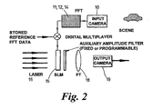
- FIG. 2 A schematic diagram of a pattern recognition apparatus in accordance with at least one aspect of the invention is shown in Figure 2 of the accompanying drawings.
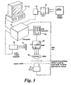
- FIG. 3 An alternative diagram, illustrating the key components parts used to construct a prototype apparatus in the laboratory, are shown in Figure 3.
- the apparatus is a hybrid system in which part of the processing is performed by digital electronics and part of the processing is performed optically. Information is converted from electrons to photons and vice-versa with the aid of two optical to electronic conversion means and one electronic to optical conversion means.
- An example application is the detection of the presence of a car in a street scene.
- the system can be used to identify whether a particular type (e.g. model) of car is present from information held in reference data. It can also be adapted, in at least one mode of operation, to identify the location of the car in the scene.
- an image of the scene is captured using a charge coupled device 10 such as a CCD camera.
- a charge coupled device 10 such as a CCD camera.
- a 718 x 512 pixel camera was used.
- the camera chosen was sensitive to visible light, although no assumptions should be made about the viable range of wavelengths recorded by the camera. Operation in the infrared is sometimes preferred as it operates day or night. Indeed, it is envisaged that the camera could be omitted and the system used to process other types of image or more abstract data which can be arranged in a two-dimensional array.
- Another example is the identification of a person's eye from a picture of a face, as shown in Figure 20.
- the camera produces one captive scene image of 512 x 512 pixels every twenty-fifth of a second.
- Each captured scene image (or selected ones) is downloaded into a temporary store in a digital memory 11.
- the digital memory 11 also stores a set of reference patterns.
- each pattern may correspond to the Fourier transform of an image of either a different type of car, or to a car viewed from a different angle, or to different cars viewed from a variety of different angles and/or from a number of different distances.
- the digital memory is provided as part of a personal computer (as shown in Figure 3). This captures scene images from the CCD camera at video rates using a dedicated image acquisition board 13.
- the captured scene image dataset stored in memory is passed to a dedicated transputer 14 (in the version as presently operating, but a transputer is not considered essential) which generates a scene pattern corresponding to a Fourier transform of the captured scene image.
- the Fourier transform is performed at the capture rate of the image acquisition board.
- the actual Fourier Transform data used to construct the scene pattern is calculated by initially calculating the complex two-dimensional Fourier Transform of the captured image dataset using an FFT routine. Next, the transputer disregards some of the information encoded in the complex data and forms a scene pattern which comprises binary phase only data. This is, of course, non-complex data.
- the reference patterns are also encoded as binary phase only data generated from the Fourier Transform of the reference images or objects. This saves memory compared to multi-bit data. In order to ensure the system operates as fast as possible, these reference Fourier Transforms are calculated prior to use of the system and are stored in memory. If only raw reference object data had been stored, each Fourier Transform of the reference would need to have been calculated in real time. This would have caused a system bottleneck.
- the reference memory may be programmable under the control of the user (possibly to change the reference patterns held in active, "live", memory).
- the reference pattern In order to recognise and/or locate a reference image in the captured scene image, the reference pattern must be compared with the captured scene pattern. For, say, four hundred reference patterns to be compared with each captured scene pattern, the process of combining these patterns must be performed at a rate of four hundred combinations within one twenty-fifth of a second if the system is to operate in real time at video capture rates.
- the captured scene image is processed to produce the binary phase only data in the scene pattern.
- the reference pattern is also in the form of a binary phase only data, the two patterns can be combined using fast simple logic circuitry, such as an exclusive-or gate.
- the combined image pattern and reference pattern forms a combined pattern which is displayed on a spatial light modulator (SLM) 15 driven by a controller 15a.
- SLM spatial light modulator
- the SLM 15 used in the laboratory prototype comprise a Fast Bit plane spatial light modulator (FBPSLM) which has been developed as part of a joint collaboration between the applicant and Cambridge University, England.
- FBPSLM Fast Bit plane spatial light modulator
- the device is provided with its own control board 15a which includes the memory for storage of the reference object datasets.
- Reference patterns can be stored as binary-phase-only information. These can be grouped together in lists.
- the reference patterns may correspond to different makes of cars. One list may comprise one reference pattern for each make. The others may comprise all the reference patterns for an individual make.
- the personal computer 12 controls (via a communication line) which list of reference patterns is to be accessed to form a particular combined pattern. It is preferred that a set of combined patterns are formed by sequentially shifting through all the relevant lists of patterns in turn. However prior information may be used to reduce the search or modify the order of search to specific lists, i.e. if it is only desired to identify one make of car. It will, of course, be appreciated that if the system searches list A and finds a match for pattern X control means may then use the fact that it was pattern X that matched to control the selection of the next list to be searched (e.g. list B instead of list C, which would have been searched if pattern Y has been matched).
- the multiplication of the scene pattern with a reference pattern is performed using an XOR gate, since only binary information is present. This is a very fast process and achieves perfect alignment of the patterns because of its digital nature.
- a currently available FBPSLM has a limited resolution and can only display 320x240 pixels which can be used.
- the FFT patterns are calculated as 512x512 pixel patterns and the data outside the central 320x240 pixels of the pattern is disregarded. This acts as a low pass spatial filtering operation. It is, however, envisaged that larger SLMs could be employed and one is currently under development. This principle of presenting to the SLM less data than is captured applies to other size ranges.
- the actual combined patterns (masks) displayed by the FBPSLM which correspond to at least part of the combined pattern, are used to modulate a light beam.
- the light beam is generated by a laser 16 prior to passing through a beam expander and a linear polariser 17.
- the expanded polarised coherent beam is shone onto the FBPSLM 15 which works in a reflection mode.
- the light reflected from the FBPSLM defines a modulated beam encoded by the pattern displayed by the FBPSLM.
- the FBPSLM is capable of displaying around ten thousand patterns (masks) per second.
- the FBPSLM modulates the phase of the light beam.
- Each pixel in the FBPSLM imparts either zero or half a wavelength of retardation onto the incident waveform (pixel by pixel). Only the relative phase is important. The state of each pixel depends on the binary value of the corresponding sample of the second intermediate dataset.
- the FBPSLM thus applies a binary phase modulation pattern to the beam.
- the reflected beam is Fourier transformed optically by a lens 18. Passage of the light through the lens transforms the modulated pattern, so as to produce in the back focal plane of the lens the required correlation pattern, which can be detected by a CCD array 19 located in the focal plane.
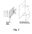
- the correlation pattern produced from the reference pattern and the scene pattern and the lens will consist of two sharply focused peaks displaced symmetrically about the origin. This is illustrated in Figure 5 for the especially simple case of a phase-reversal grating.
- a large peak is formed at the origin which is essentially due to interpixel regions of the SLM. The presence of the two peaks is a side effect of the binarisation of the phase of the Fourier transform data.
- a peak is present when a reference pattern is correlated with a scene pattern, it can be assumed that the reference is present in the scene. If no correlation peaks are formed, the reference image can be assumed not to be present. The decision can be made by means of a threshold circuit.
- the correlation pattern also enables the location of the reference image in the scene to be determined with some ambiguity.
- the location of the peaks in the (x,y) plane of the correlation pattern is related to the position of the reference image in the scene.
- a drill bit may be guided towards an identified area where a hole is required. It can be arranged that as the first optical to electronic means is steered towards the reference object in the scene the two peaks converge into one.
- the output camera placed in the focal plane of the lens produces an output signal which can, in turn, be analysed to detect the presence and/or location of a reference object in the scene.
- the output of the camera is integrated over time, e.g. so as to cover a number of reference object scales and/or orientations to reduce the required readout frame rate of the camera from the current ideal value of say 10kHz.
- a signal may be produced from the pattern recorded by the camera which could be digitally processed to identify correlation peaks.
- the captured scene image representing the scene could be displayed on a screen and a marker may be overlaid to indicate the location of a reference object in the scene.
- This marker could, for instance, be a cross-wire. This could, for example, be useful when using the invention in combination with a medical laser adapted to burn away certain tissue parts and not others if it is appropriately aligned and powered.
- the first optical to electronic conversion means (the input camera) could be capturing an image frame at the rate of twenty-five frames per second. With a set of four hundred reference patterns, ten thousand patterns will be displayed on the SLM each second. This, in turn, means that the output camera ideally needs to have an output rate of ten thousand frames per second, but this is not essential (for example the output signal could be integrated).
- the essence of the invention is the combination of digital and optical transforms in a pattern recognition scheme.
- the preferred transformation for use on the digital data is 1-bit binary-phase-only data derived from the Fourier transform.
- binary phase only data is eminently suited for use with fast binary modulators such as ferro-electric liquid crystal SLMs, including the FBPSLM.
- Multiple bit-level transform data could be used as an alternative, although for maximum benefit a spatial modulator based on several modulation levels would be needed. We are unaware of any suitable commercial devices of this type at the present time.
- phase-only Fourier transform information rejecting amplitude information
- the main reason for using binarised phase-only information for the first intermediate dataset and reference datasets is its inherent compatibility with liquid crystal SLMs with binary responses, and the faster speeds at which binary data can be multiplied using, say, an exclusive-or gate.
- binary phase information results in a degradation of performance due to the coarseness of the quantisation of the phase data.
- binary data results in two correlation peaks being formed in the output plane of the Fourier transforming lens as shown illustratively in Figure 5.
- the location of the correlation peaks in the output plane is a measure of the relative displacements of the reference object in the picture used to generate the reference dataset and the item to be identified in the captured scene. For example, if the object and reference are equally displaced from the origins of their respective scenes, there is no relative displacement, and a single output peak occurs at the origin.
- the reference can be located arbitrarily. In the case of object tracking this provides a valuable degree of freedom. Since it is often required to track a spot on a moving sought object present in the scene. It is convenient to make this spot the centre of the reference image (used to create the reference pattern) for each scale/orientation of the reference object sought. In this case when the spot on the reference object is in the centre of the input plane, the output correlation peak is at the centre of the output plane. Thus, in the tracking process the objective is to keep the correlation peak at the centre of the output plane when the desired region of the scene object is always centrally aligned with a tracking device (e.g. a camera or drill).
- a tracking device e.g. a camera or drill
- phase-only filters when the scene is dominated by the object and perfectly matches the reference object, so that there is a perfect phase-conjugate relationship between the (binarised phase-only) Fourier Transforms of the object and reference: - in these circumstances the field exiting the SLM is a plane wave of uniform amplitude (assuming the input illumination is uniform) so that the output is theoretically an Airy function, independently of the object/reference. This may be useful, as it has very low sidelobe levels, in contrast to the ACF of a general object/reference and a fixed intensity. If the illuminating laser has a Gaussian intensity profile, the output is further smoothed. This Gaussian profile could reduce the sensitivity of the system to a precise match between object and reference, since it is equivalent to the use of a filter which reduces the high-spatial-frequency content of the output.
- the chirp phase pattern is in one embodiment calculated and added to the reference phase pattern before the resultant reference pattern is binarised.
- the resultant combined spectrum from the reference and input patterns is then displayed on the FBPSLM and Fourier transformed optically by a lens. It can be shown that due to the chirp the two correlation peaks produced are focused to planes either side of the focal plane of the lens in the z-direction at distances z' and z". It can also be shown that the positions of the correlation peaks in the x-y plane are scaled depending on the size of the chirp employed.
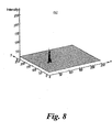
- Figures 7 and 8 show experimentally recorded results of the correlation signals produced by reference patterns with and without a chirp respectively.
- Figure 7 was recorded with the camera placed at the focal plane of the lens when no chirp was applied.
- Figure 8 was recorded when a chirp was applied: the camera was displaced in the z-direction until one correlation peak was in focus at plane z'.
- Figure 8 successfully demonstrates that the second correlation peak and the DC component are de-focused.
- the chirp as an external structure to the SLM, which is either fixed or variable.
- the chirp should, ideally, be added before the pattern is binarised and can be added to both patterns or to only one of the patterns. It is probably more convenient to pre-calculate the pattern and add it to the reference pattern. It is therefore possible to compose a set of patterns with different chirps so that the chirp can be chosen randomly from a list in real-time or sequentially to produce a scanning focus in the z-direction. Combination with a linear chirp allows the focus to be varied in three dimensions in real-time. For example, the current design of the FBPSLM allows the chirp pattern to be changed approximately ten thousand times per second. Applications could include the memory access of optical discs and holographic memory without the requirement for mechanically moving parts.
- variable chirp may be required, for example, time/frequency analysis in Wigner transform or Ambiguity function, where an unknown chirp may be present in the input signal.
- the purpose of applying additional chirps is to find the one which negates the unknown chirp in order to retrieve a desired signal.
- the chirp could also be used by an SLM with more than two modulation levels (i.e. not binary). This would have the advantage that multiple modulation levels produce only one correlation peak and the optical throughput is therefore more efficient. Although the ambiguity of sought-object location is removed by having only one correlation peak there is still a problem caused by the presence of a DC peak. Therefore, it is still beneficial to use the chirp to defocus the DC peak. This property has not been discussed in the literature to our knowledge.
- the chirp has a similar mathematical description to a lens and it has been shown experimentally that it is not necessary to use a lens in conjunction with the chirp. This simplifies the optical system design.
- a chirp function may be simply multiplied with an FFT pattern. It can be pre-calculated or even accessed from a "look-up" table. Alternatively, the chirp could be applied to the signal by convolution.
- the spatial light modulator The spatial light modulator
- FBPSLM Fast Bit Phase Spatial Light Modulator
- Other SLMs including other silicon backplane devices
- the FBPSLM comprises a 320x240 pixel array with a fill factor of 65%. This allows a maximum frame rate of 22.7KHz, which is sufficient for the display of in excess of ten thousand patterns per second.
- the pixels are of the DRAM type.
- each pixel will have two modulation states. For phase modulation, these will correspond to different retardations.
- the voltages applied should, ideally, be varied (e.g. alternated) in polarity so that the net voltages seen by the pixel material over time is substantially zero of DC-balanced.
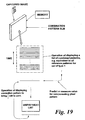
- the SLM In order to reduce the amount of redundant time in the SLM (both in the pattern recognition scheme shown in Figures 2 and 3 and in any other system incorporating an SLM) it is proposed to generate a list of patterns to be displayed on the SLM.
- the voltages applied across each pixel over time when displaying the list can then be summed.
- a single pattern can then be calculated from the sum value and a single pattern required to produce a DC-balance can be displayed on the SLM.
- the patterns in the list may be displayed so that some have a negative voltage and some have a positive voltage to approximate to a zero net voltage. They may be displayed as alternate positive or a negative voltage patterns.
- the voltage applied to a pixel for, say, two, three or four or more patterns can be summed. It is envisaged that a list of patterns would have perhaps hundreds of combined patterns (combined scene pattern and reference pattern). It is envisaged that a list will comprise all of the combined patterns generated by a reference pattern set for a particular article to be identified - that is to say the list could be displayed on the SLM and then after displaying all correlation combined patterns for a particular predetermined article the SLM pixels/material is biased by a biasing voltage to compensate for the net effect of the voltages applied by the list. A balance voltage can then be calculated and used to control the pixel.
- the balance pattern needs only to be applied once for each summation, but may be of long duration and different for each pixel - some may need to flip i.e. to negative or positive, in this period.
- Figure 19 of the accompanying drawings incorporated in an optical pattern recognition system where a combined pattern is to be displayed on the SLM.
- the smart SLM can have upper and/or lower thresholds for light intensity and alter its interaction with incident light dependent upon the intensity of the incident light.
- the value of these thresholds can preferably be changed by a user independently e.g. by using a programmable smart SLM.
- the thresholding function of a smart SLM could be performed digitally, and only signals from a pixel that were above a predetermined (possibly variably controlled) value would be passed on by the pixel.
- the correlation pattern is focused onto a CCD camera.
- large numbers of reference/image correlations are made for each capture image, considerable strain is placed on the speed of the output camera. For instance, if four hundred references are correlated per capture image, and the capture camera is operated at a video rate of, say, twenty-five frames per second, then the output camera must process ten thousand patterns per second. It is envisaged that the output camera may therefore place limits on the maximum number of reference correlations that can be made.
- an output camera of modest size (e.g. 48 x 48 pixels) and high frame rate, several kHz, can be used.
- the laser light source has been replaced by a VCSEL array 100.
- the CCD camera has been replaced by a linear output detector array 101.
- the VCSEL array comprises a linear array of laser diodes, the centre of the array coinciding with an axis passing through the centre of the SLM 102 and focusing lens 104 and 105 (where provided).
- the linear detector array is also centred about this axis, but is orthogonal to the VCSEL array, as shown in Figure 16.
- each row of pixels can be read out in parallel, all 512 rows being read in one hundredth of a second. This could in itself be a useful modification to a CCD camera, as all 512 rows could be read in parallel.
- Each output can be passed through a threshold circuit to detect correlation peak(s) corresponding to the presence of the reference object in the scene.
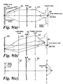
- the system shown in Figure 9 solves the problem in a different manner by "moving" the light source so that the two-dimensional output pattern is stepped across a linear array.
- the VCSEL could comprise 512 laser diodes, and the linear array could comprise 512 detectors. By switching one laser diode on at a time, and cycling through all 512 diodes within the time that a single pattern is displayed on the SLM, the whole two-dimensional pattern can be scanned across the linear array.
- a number of rows of detectors are provided. Each row is read out in alternate directions, i.e. first row to the left, second to the right, third to the left, etc.
- a "Smart" spatial light modulator which can be adapted to act as a non-linear filter, which can in one mode be arranged to pass only strong optical peaks which, for example, correspond to a correlation peak. Since this would remove low level background clutter, interrogation of the integrated output signal from a CCD becomes an attractive proposition. This is especially true if all references are centred to a common point, since the output peak will then correspond to that point regardless of scale or orientation of the reference.
- FIG. 10 A different problem which could also be solved by a "smart" SLM is shown in Figure 10.
- a distant scene 200 is observed by the viewer through a lens L 201, which forms an intermediate image in the plane P1 of Figure 1.
- a bright spot B1 causes a bright spot B2, in this intermediate image plane, and causes a bright spot B3 on the retina 103 of the viewer.
- the bright spot B3 may dazzle the viewer or damage the retina or cause blooming in a camera (or over-exposure in a conventional camera with a film).
- the proposed "smart" SLM would limit the intensity of the bright spot B3.
- a simple "smart" SLM is shown in Figure 11. It comprises a rectangular two-dimensional substrate 300 carrying an array of identical elements, all powered by a common source (i.e. battery) through a conducting electrode structure provided on the substrate.
- the electrode structure could be metallic or formed from an optically-transparent conductor such as Indium Tin Oxide (ITO).
- ITO Indium Tin Oxide
- the detector 301, an associated amplifier (not shown), a comparator (not shown) and a transistor (also not shown - and in some embodiments not present) occupy a small area separated from a larger transmissive area of liquid crystal pixel 302.
- the SLM is configured as an amplitude device, not a phase device, and need not be liquid crystal.
- the SLM of Figure 11 functions as follows. Light incident upon the detector 301 generates a small photo-current. This is amplified by the amplifier and fed to one input of a comparator. The other input of the comparator is connected to a reference voltage. When sufficient light is incident upon the detector to produce an input to the comparator greater than the reference, the comparator output will trip, in turn operating the transistor to switch the associated liquid crystal pixel 302. Thus, it will be readily appreciated, that by choosing an appropriate reference voltage dependent upon the detector sensitivity and amplifier gain, the pixel can be made to switch at a predetermined incident light intensity.
- the simple SLM shown in Figure 11 will block off all light above a certain threshold intensity (in fact it is difficult to block the light completely and it will be severely attenuated to a set degree - i.e. the pixel is either "clear” or "dark”).
- the alternate modulator shown in Figure 12 has been devised.
- the detecting element is located behind its associated pixel rather than to one side. In this case, a bright spot will not be completely extinguished, but will be limited to a threshold level which is self-consistent. This arrangement would be preferred for eye protection for example, or for use with a camera.
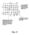
- FIG. 21 An alternate smart SLM is shown in Figure 21.
- one detector 301 controls a set of four adjacent pixels of modulating medium 302.
- the connections to the comparator could be reversed (or the operation of the transistor could be reversed), or some other modification made, so that the pixel blocks out light until the light on the detector exceeds the threshold level. This can allow integration of the thresholded signals to be feasible, since only the strong correlation peaks are passed to the output camera.
- the output of the detector could be connected to any logic circuit to control the operation of each pixel.
- One detector and associated circuit could be associated with more than one pixel.
- the detection could be provided at the centre of a 2x2 array of pixels in the SLM.
- a "smart" spatial light modulator can be incorporated into a correlation system in a number of ways.
- a smart SLM adapted to attenuate high intensity portions of the image scene could be provided in front of (or in an intermediate image plane in front of) an input camera adapted to capture the scene image. This could, for example, prevent a bright sun or light from causing the camera to bloom, or film to be over-exposed. The sunlight could be completely blocked, or just more preferably attenuated to a lower intensity.
- the smart SLM filter could be built into the camera, or built into a lens unit, or be an add-on filter unit which is attached to the camera, or associated in some other way.
- a similar "smart" SLM could also be incorporated into the optical correlator after the SLM used to display the combined patterns or chirped combined patterns but before an output camera.
- the combined signal includes a chirp to defocus one of the correlation peaks in a binary system a camera could be located in the plane furthest from the SLM which contains a correlation peak.
- a smart SLM could then be located in an intermediate plane which will contain the other correlation peak.
- the smart SLM could attenuate the unwanted peaks in that plane to improve discrimination.
- a similar arrangement could be used to remove the DC peak by placing a smart SLM in the plane which contain the DC peak.
- An alternative smart SLM which removes (or at least attenuates) light below a threshold intensity whilst passing (or reflecting if a reflection device) light with intensity above the threshold could be placed in front of the output camera. It could form part of the output camera itself. This would be adapted to remove background clutter. In such a case, the output of the output camera could be integrated over a number of combined patterns. If an output voltage over a predetermined level is produced, it can be assumed that reference from the reference pattern set used to generate the combined patterns was present.
- the reference patterns are divided into lists of patterns.
- the lists may consist of a master list and sublists.
- the master list may contain at least one representative reference from each sublist.
- each sublist may comprise different views of a particular car, with the master list comprising a view of each type of car.
- the reference patterns could be synthetic discriminant functions, both in this last idea, and in earlier discussions.
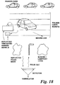
- a light source is provided which is adapted to illuminate the scene with a series of short duration bursts of light.
- wavelengths other than optical could be used provided the capture camera is compatible (or indeed other signal transfer propagating mechanisms other than e.m.). This method is shown in Figure 18 for a typical scene.
- a short pulse of radiation is emitted.
- the pulse may be of the order of 1 nano-second, giving a spatial extent of, say, 30 cms for a visible wavelength pulse.
- the optical field reflected is then passed through a pulsed image intensifier and recorded on a camera.
- the captured image recorded by the camera is then processed to form a first scene pattern as shown in the embodiment of Figures 2 and 3 and compared with one or more references. This is then repeated for a second pulse which can be detected allowing for elapsed time which is greater than that at which the first captured image is logged.
- An alternative version is to send out a first pulse and measure return time to get the range - it then acts in a rangefinder mode. It is then possible to perform a series of ranges around this average.
- a form of three-dimensional image of the scenery can be constructed.
- Each "layer" of the image may be correlated with one or more reference images. This also enables an object in a scene that would otherwise be obscured by background clutter to be identified.
- the spatial resolution is dominated, in practice, by the length of the emitted pulse, as the length of time for which the intensifier operates. As shown in Figure 18, unwanted reflections from parked cars and bushes can be eliminated. This is a different advantage, in addition to the possibility of three-dimensional imaging.
- Another advantageous feature of the new hybrid digital/optical pattern recognition apparatus is that it is possible to "tile" more than one mask pattern onto the SLM to produce several corresponding correlation patterns in the output plane of the focusing lens. This is possible because it is not necessary to have the DC frequency of the pattern on the optical axis (as in a classical Vander Lugt correlation).
- a defined optical axis is present.
- the spatial frequencies are all centred on axis.
- the reference pattern which must be placed on the Fourier transform plane must be similarly aligned on this axis.
- the spatial frequencies have no defined order. This allows the SLM to display, say, four or more patterns simultaneously. For example, these may be tiled in four quadrants as shown in Figures 13(a) to (c). This has a number of distinct advantages.
- the spatial frequencies displayed on the SLM could be arranged in any order (as distinct from having a requirement that spatial frequencies be carefully ordered away from the optical axis - we can map the same combined pattern to different regions of the SLM and still operate properly).
- the rate of correlation can be increased as the number of tiled patterns increases. Each tile will produce its own correlation pattern when Fourier transformed, and one or more detectors (such as CCDs) could work in parallel on the patterns.
- tiled patterns would also allow a number of different chirp patterns to be applied to a single combined pattern in parallel. This may be desirable to separate the correlation regions and avoid cross-talk.
- a multi-spectral image could be captured (say, red, green, blue colours) which can be processed in parallel, each tile corresponding to one colour for example.
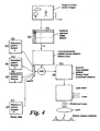
- FIG. 14 A yet further modification is shown in Figure 14.
- the pattern recognition apparatus 500 is split into two sections.
- One section 501 comprises an optical input device 502 which is connected via an optical cable 503 to a computer 504 or other electronic device.
- the optical input device receives the input capture data which it transmits over the optical cable.
- the computer which in this example is battery-powered and is provided in a self-contained unit, generates the scene images and scene patterns and transmits them over a second optical fibre 505 to a base unit 506.
- optical input devices can be located remotely from the electronics by up to tens of kilometres.
- the optical fibre is immune to electro-magnetic interference and so can enable input capture data to be obtained in electromagnetically noisy environments.
- the present invention comprises, when looked at one way, a hybrid digital/optical correlator.
- Many advantageous features have been disclosed, many of which have applications far wider than the field of pattern recognition. For instance, many of the disclosed apparatus and methods, whilst developed primarily as part of a complete pattern recognition system, will find wider applications in other fields. Protection may be sought for any novel individual feature in its own right.
- Frier transform is intended to include different types of transform including Sine, Cosine, Hartley, Wavelet transforms, etc. Whilst each transform has slightly different properties, they can all be implemented digitally in order to define the same patterns, reference patterns, and combined patterns used in the disclosed pattern recognition apparatus.
- the invention can, of course, be performed with optical light or electromagnetic radiation of any wavelength, and nmr (mri) imagery.
- medical imaging/medical applications is a field of great potential for the inventions - controlling the alignment and/or movement of a medical laser relative to known body structures, possibly automatically or remotely and, for example, only allowing the medical laser to operate when a correct pattern match has been found (it is correctly aligned) may be an application.
- pattern recognition is a term used to describe the process of identifying the presence of a reference object in a scene.
- the scene image and reference object may be real things such as cars (objects) in a queue (scene), or may be more abstract quantities such as arrays of data or even a string of data. For simplicity they are always referred to as the scene image and reference object.
- Synthetic discriminant functions are effectively combinations of reference data, for example a combination of a car sideways on and head on. They are used to reduce the number of references necessary to identify the presence of an object in a scene.
- optical-to-electronic converters these are typically cameras or detector arrays.
- SLMs Spatial Light Modulators.
- the SLMs described as examples in the text are invariably pixellated devices, i.e. comprise arrays of individual modulating elements. Many types of SLM exist. The most common devices employ Liquid Crystals or micromachined elements as light modulating means.
- SLMs can operate in many ways, for example in transmission or in reflection.
- SLMs that work in transmission. It is to be understood that SLMs working in reflection can also be used in slightly modified configurations, and that protection for those is intended.
- the patterns displayed on SLMs are referred to as masks.
- a lens In the systems described a lens often forms the Fourier transform of the mask pattern, the output being monitored in the back focal plane of the lens. This forms the output (pattern) of the correlator. Nevertheless we often refer to this as focusing , since in the correlation process when the sought reference object is present in the scene, light is focused to form a correlation peak in the output focal plane.
- Fourier Transforms there is a distinction between Fourier Transforms and Inverse Fourier Transforms , but the difference is of no practical importance, and all such transforms are described as Fourier Transforms here. Similarly the term Fourier Transform is used to cover closely related transforms such as cosine transforms.
- the process of correlation between reference objects and the scene can be performed in the spatial frequency domain.
- the first step in this process is to multiply the Fourier Transform of one with the complex conjugate of the Fourier Transform of the other.
- the second step is to take an inverse Fourier Transform of the product.
- phase-only data in the first step it is only necessary to calculate the difference of the phases. In the case of binarised phase-only data this is most easily accomplished through an XOR logic operation. In the text "combined" should be understood in this sense.
- the patterns described in the text are generated from the Fourier Transforms of the object or scene.
- the location of an object in a scene is defined by co-ordinates (x,y).
- a chirp waveform is an analogue waveform of constant amplitude and linearly varying frequency.
- a two-dimensional binary optical approximation to this is a phase-reversal zone plate lens. For simplicity in the text we refer to this as a zone plate lens.
- zone plate lens is included, often in conjunction with a conventional glass lens. Unless specifically mentioned it can be assumed that this zone plate lens is absent in the descriptions of operation. In this case the correlator output is invariably taken in the back focal plane of the real glass lens.
- SLM Segment SLM
Landscapes
- Physics & Mathematics (AREA)
- General Physics & Mathematics (AREA)
- Engineering & Computer Science (AREA)
- Optics & Photonics (AREA)
- Multimedia (AREA)
- Theoretical Computer Science (AREA)
- Image Analysis (AREA)
- Length Measuring Devices By Optical Means (AREA)
- Photometry And Measurement Of Optical Pulse Characteristics (AREA)
- Image Processing (AREA)
- Holo Graphy (AREA)
- Wire Bonding (AREA)
- Microscoopes, Condenser (AREA)
- Character Discrimination (AREA)
- Lenses (AREA)
- Optical Couplings Of Light Guides (AREA)
- Optical Modulation, Optical Deflection, Nonlinear Optics, Optical Demodulation, Optical Logic Elements (AREA)
- Prostheses (AREA)
- Eyeglasses (AREA)
- Studio Devices (AREA)
Abstract
Description
Claims (31)
- An apparatus for detecting the presence of one or more images of a known predetermined kind in a scene, comprising:- means adapted to produce a scene image corresponding to a scene; a digital input means comprising: first electronic processing means adapted to process at least a part of the scene image to produce a scene pattern corresponding to the Fourier Transform of at least part of the scene image, storage means adapted to store one or more reference patterns, each reference pattern comprising the Fourier Transform of a respective reference image, second processing means adapted to electronically combine the scene pattern with a reference pattern to produce a combined pattern; and an optical output means adapted to produce an optical output that is derived from the combined pattern, characterised in that the apparatus comprises at least two light emitting devices, each light emitting device being spaced at a different position relative to an optical axis of the apparatus; a controller adapted to control the illumination of each device sequentially; and a spatial light modulator comprising said optical output means and being adapted to display said combined pattern and being provided between the light emitting devices and an output detector adapted to receive light which has been modulated by the spatial light modulator.
- Apparatus according to claim 1 in which an optical element with focusing power is provided between the light emitting devices and the detector.
- Apparatus according to claim 2 in which the optical element is a lens or mirror.
- Apparatus according to claim 2 or claim 3 in which the optical element is provided between the spatial light modulator and the detector.
- Apparatus according to any one of claims 2 to 4 in which a further optical element is provided, one of the optical elements being provided between the light emitting devices and the spatial light modulator and the other of the optical elements between the spatial light modulator and the detector.
- Apparatus according to any preceding claim in which the detector array comprises at least one line of detectors.
- Apparatus according to any preceding claim in which there is a detector array having a longitudinal direction and in which the light emitting devices are arranged in a line extending substantially orthogonally to the longitudinal direction of the detector array.
- Apparatus according to any preceding claim in which an array of light emitting devices is aligned substantially orthogonally to the optical axis passing through the centre of the spatial light modulator.
- Apparatus according to any preceding claim in which a collimating lens is provided between the light emitting devices and the spatial light modulator.
- Apparatus according to any preceding claim in which a polariser is provided between the light emitting devices and the spatial light modulator.
- Apparatus according to any preceding claim in which the polariser forms part of the spatial light modulator.
- Apparatus according to any preceding claim in which the light emitting devices comprise a device from the list: lasers, laser diodes.
- Apparatus according to any preceding claim which is adapted such that in use only one light emitting device emits a light beam at any instant.
- Apparatus according to any preceding claim in which the array of devices comprises a VCSEL array.
- Apparatus according to any preceding claim in which the detector comprises an array of detector elements.
- Apparatus according to any preceding claim in which the detector comprises a linear array of one or more lines of detector elements.
- Apparatus according to any preceding claim in which there is a linear array of light emitting devices and a linear output detector array, and in which the arrays are crossed so that in use light from the light emitting devices of the light emitting device array can scan over the spatial light modular and create an equivalent series of optical outputs stepping over the output detector.
- Apparatus according to any preceding claim in which the spatial light modulator is selected from the list: transmissive device, reflective device.
- Apparatus according to any preceding claim in which the spatial light modulator is a binary device.
- Apparatus according to any preceding claim in which a thresholding device is provided prior to the detector array, the thresholding device allowing light to reach the detector or detector array if the intensity of the light is above a predetermined threshold.
- Apparatus according to any preceding claim in which there is a lens or other focusing optical element having an optical axis, and there is a linear array of light emitting devices which is substantially orthogonal to the optical axis, and in which there is a detector array which is substantially orthogonal to both the optical axis and the line of the linear array of light emitting devices.
- Apparatus according to any preceding claim in which there is a detector array having at least one line of detectors, and in which read out circuitry is provided for successive detectors in the lines of detectors of the array disposed alternately to opposite sides of their line.
- Apparatus according to claim 22 in which there is a single line of detectors in the detector array.
- Apparatus according to claim 23 in which there are at least three light emitting devices in a line.
- Apparatus according to claim 24 in which the controller is adapted to illuminate next adjacent light emitting devices in order in turn in the line.
- Apparatus according to any preceding claim in which the light emitting devices are provided in an array.
- A method of detecting the presence of one or more reference images in a scene comprising the steps of producing an image scene corresponding to at least part of a scene; processing at least a part of the captured image scene to produce a scene pattern corresponding to the Fourier Transform of a captured scene image; electronically combining the scene pattern with at least one reference pattern corresponding to the Fourier Transform of a reference object to produce a combined pattern and producing an optical output derived by the combined pattern; the method further comprising providing at least two light emitting devices in an optical system, the at least two devices being at different positions relative to an optical axis of the system, and the method further comprising the steps of controlling the devices so that each device is illuminated sequentially effectively to move the source of light beam, and providing at least one detector means in a plane which contains the optical pattern which is to be monitored, whereby controlling the illumination of the devices scans the two-dimensional pattern across the detector means.
- A method according to claim 27 in which a lens, mirror, or other focusing optical element is provided in the system and the light emitting devices are at different positions relative to the optical axis of that optical element.
- A method according to claim 27 or claim 28 in which a spatial light modulator is provided and it is driven to display a pattern corresponding to at least a combination of the Fourier Transform of a scene pattern and of a reference pattern.
- A method according to any one of claims 27 to 29 in which there is a line of more than two light emitting devices and next adjacent light emitting devices are illuminated in turn along the line.
- A method of pattern recognition correlation which uses the method of any one of claims 27 or claim 30.
Priority Applications (3)
| Application Number | Priority Date | Filing Date | Title |
|---|---|---|---|
| EP05025420A EP1632883A3 (en) | 1998-09-24 | 1998-09-24 | Optical pattern recognition with a binary phase-only filter for image tracking |
| AT03017175T ATE310992T1 (en) | 1998-09-24 | 1998-09-24 | IMPROVEMENTS TO PATTERN RECOGNITION |
| EP03017175A EP1400917B1 (en) | 1998-09-24 | 1998-09-24 | Improvements relating to pattern recognition |
Applications Claiming Priority (1)
| Application Number | Priority Date | Filing Date | Title |
|---|---|---|---|
| PCT/GB1998/002876 WO2000017809A1 (en) | 1998-09-24 | 1998-09-24 | Improvements relating to pattern recognition |
Related Child Applications (1)
| Application Number | Title | Priority Date | Filing Date |
|---|---|---|---|
| EP03017175A Division EP1400917B1 (en) | 1998-09-24 | 1998-09-24 | Improvements relating to pattern recognition |
Publications (2)
| Publication Number | Publication Date |
|---|---|
| EP1116169A1 EP1116169A1 (en) | 2001-07-18 |
| EP1116169B1 true EP1116169B1 (en) | 2003-07-30 |
Family
ID=10826798
Family Applications (2)
| Application Number | Title | Priority Date | Filing Date |
|---|---|---|---|
| EP98944093A Expired - Lifetime EP1116169B1 (en) | 1998-09-24 | 1998-09-24 | Improvements relating to pattern recognition |
| EP99949099A Expired - Lifetime EP1116170B1 (en) | 1998-09-24 | 1999-09-24 | Programmable lens assemblies and optical systems incorporating them |
Family Applications After (1)
| Application Number | Title | Priority Date | Filing Date |
|---|---|---|---|
| EP99949099A Expired - Lifetime EP1116170B1 (en) | 1998-09-24 | 1999-09-24 | Programmable lens assemblies and optical systems incorporating them |
Country Status (11)
| Country | Link |
|---|---|
| US (1) | US7067784B1 (en) |
| EP (2) | EP1116169B1 (en) |
| JP (2) | JP4197844B2 (en) |
| CN (1) | CN1133952C (en) |
| AT (2) | ATE246380T1 (en) |
| AU (2) | AU9176398A (en) |
| CA (2) | CA2345262A1 (en) |
| DE (2) | DE69816876T2 (en) |
| MX (1) | MXPA01003035A (en) |
| NO (1) | NO20011519L (en) |
| WO (2) | WO2000017809A1 (en) |
Families Citing this family (33)
| Publication number | Priority date | Publication date | Assignee | Title |
|---|---|---|---|---|
| US20020122595A1 (en) * | 1999-06-04 | 2002-09-05 | Rikk Crill | Apparatus and method for radial and angular or rotational analysis of images for shape content and matching |
| US7103223B2 (en) | 2000-03-27 | 2006-09-05 | Look Dynamics, Inc. | Apparatus and method for radial and angular or rotational analysis or images for shape content and matching |
| CA2349828A1 (en) * | 2001-06-06 | 2002-12-06 | Andrew M. Zador | Method, apparatus, and system for extracting denoised, high-resolution images, texture, and velocity from a lower-resolution, noisy detector |
| IL174590A (en) * | 2005-03-29 | 2015-03-31 | Yoel Arieli | Method and imaging system for analyzing optical properties of an object illuminated by a light source |
| US7634771B2 (en) * | 2005-04-29 | 2009-12-15 | Sap (Ag) | Object generation in packages |
| GB0510470D0 (en) | 2005-05-23 | 2005-06-29 | Qinetiq Ltd | Coded aperture imaging system |
| GB2434934A (en) | 2006-02-06 | 2007-08-08 | Qinetiq Ltd | Processing coded aperture image data by applying weightings to aperture functions and data frames |
| GB2434937A (en) | 2006-02-06 | 2007-08-08 | Qinetiq Ltd | Coded aperture imaging apparatus performing image enhancement |
| GB0602380D0 (en) | 2006-02-06 | 2006-03-15 | Qinetiq Ltd | Imaging system |
| GB2434935A (en) | 2006-02-06 | 2007-08-08 | Qinetiq Ltd | Coded aperture imager using reference object to form decoding pattern |
| GB2434936A (en) | 2006-02-06 | 2007-08-08 | Qinetiq Ltd | Imaging system having plural distinct coded aperture arrays at different mask locations |
| GB2434877A (en) | 2006-02-06 | 2007-08-08 | Qinetiq Ltd | MOEMS optical modulator |
| GB0615040D0 (en) | 2006-07-28 | 2006-09-06 | Qinetiq Ltd | Processing method for coded apperture sensor |
| US8692974B2 (en) * | 2007-06-14 | 2014-04-08 | Asml Netherlands B.V. | Lithographic apparatus and device manufacturing method using pupil filling by telecentricity control |
| US8189172B2 (en) * | 2007-06-14 | 2012-05-29 | Asml Netherlands B.V. | Lithographic apparatus and method |
| US7988297B2 (en) | 2007-10-19 | 2011-08-02 | Look Dynamics, Inc. | Non-rigidly coupled, overlapping, non-feedback, optical systems for spatial filtering of fourier transform optical patterns and image shape content characterization |
| EP2321819A4 (en) * | 2008-09-08 | 2014-03-12 | Ned M Ahdoot | Digital video filter and image processing |
| JP5423222B2 (en) * | 2009-08-07 | 2014-02-19 | ソニー株式会社 | Position detection apparatus and position detection method |
| JP5515848B2 (en) * | 2010-02-24 | 2014-06-11 | 大日本印刷株式会社 | Optical element and manufacturing method thereof |
| CN110749951B (en) * | 2012-10-24 | 2022-12-30 | 视瑞尔技术公司 | Lighting device |
| US9110240B2 (en) * | 2013-03-05 | 2015-08-18 | Rambus Inc. | Phase gratings with odd symmetry for high-resolution lensed and lensless optical sensing |
| US20140267617A1 (en) * | 2013-03-15 | 2014-09-18 | Scott A. Krig | Adaptive depth sensing |
| US10591870B2 (en) | 2014-05-01 | 2020-03-17 | Celloptic, Inc. | Birefringent lens interferometer for use in microscopy and other applications |
| CN104091977B (en) * | 2014-05-06 | 2016-06-15 | 无锡日联科技股份有限公司 | The detection method of wound lithium-ion battery |
| US10284825B2 (en) | 2015-09-08 | 2019-05-07 | Rambus Inc. | Systems with integrated refractive and diffractive optics |
| JP6814983B2 (en) * | 2016-03-31 | 2021-01-20 | パナソニックIpマネジメント株式会社 | Imaging device |
| JP2019515354A (en) * | 2016-05-06 | 2019-06-06 | セルオプティック、インコーポレイテッドCelloptic, Inc. | Birefringent lens interferometer for use in microscopy and other applications |
| US10649118B2 (en) * | 2016-09-26 | 2020-05-12 | Hitachi, Ltd. | Imaging device |
| US10620447B2 (en) | 2017-01-19 | 2020-04-14 | Cognex Corporation | System and method for reduced-speckle laser line generation |
| CN117252247A (en) | 2017-09-20 | 2023-12-19 | 视觉动力公司 | Sensor display device |
| US11665324B2 (en) * | 2018-08-06 | 2023-05-30 | University Of Maryland, College Park | High fidelity configuration for two-photon SLM microscopy |
| WO2023139922A1 (en) * | 2022-01-20 | 2023-07-27 | 株式会社フジクラ | Optical computation device and optical computation method |
| CN116538949B (en) * | 2023-07-03 | 2023-09-15 | 湖南大学 | High-speed dynamic process DIC measurement device and method based on time domain super resolution |
Family Cites Families (1)
| Publication number | Priority date | Publication date | Assignee | Title |
|---|---|---|---|---|
| GB2282505A (en) * | 1993-09-23 | 1995-04-05 | Sharp Kk | Three dimensional imaging apparatus |
-
1998
- 1998-09-24 JP JP2000571399A patent/JP4197844B2/en not_active Expired - Fee Related
- 1998-09-24 WO PCT/GB1998/002876 patent/WO2000017809A1/en active IP Right Grant
- 1998-09-24 MX MXPA01003035A patent/MXPA01003035A/en unknown
- 1998-09-24 AU AU91763/98A patent/AU9176398A/en not_active Abandoned
- 1998-09-24 EP EP98944093A patent/EP1116169B1/en not_active Expired - Lifetime
- 1998-09-24 AT AT98944093T patent/ATE246380T1/en not_active IP Right Cessation
- 1998-09-24 CN CNB988143313A patent/CN1133952C/en not_active Expired - Fee Related
- 1998-09-24 DE DE69816876T patent/DE69816876T2/en not_active Expired - Lifetime
- 1998-09-24 CA CA002345262A patent/CA2345262A1/en not_active Abandoned
-
1999
- 1999-09-24 AU AU62098/99A patent/AU6209899A/en not_active Abandoned
- 1999-09-24 AT AT99949099T patent/ATE261602T1/en not_active IP Right Cessation
- 1999-09-24 US US09/787,767 patent/US7067784B1/en not_active Expired - Fee Related
- 1999-09-24 JP JP2000571400A patent/JP2002525685A/en active Pending
- 1999-09-24 EP EP99949099A patent/EP1116170B1/en not_active Expired - Lifetime
- 1999-09-24 WO PCT/GB1999/003000 patent/WO2000017810A1/en active IP Right Grant
- 1999-09-24 DE DE69915499T patent/DE69915499T2/en not_active Expired - Fee Related
- 1999-09-24 CA CA002345261A patent/CA2345261A1/en not_active Abandoned
-
2001
- 2001-03-23 NO NO20011519A patent/NO20011519L/en not_active Application Discontinuation
Also Published As
| Publication number | Publication date |
|---|---|
| WO2000017810A1 (en) | 2000-03-30 |
| CN1133952C (en) | 2004-01-07 |
| NO20011519D0 (en) | 2001-03-23 |
| DE69816876D1 (en) | 2003-09-04 |
| MXPA01003035A (en) | 2002-04-09 |
| CA2345261A1 (en) | 2000-03-30 |
| JP4197844B2 (en) | 2008-12-17 |
| JP2002525762A (en) | 2002-08-13 |
| NO20011519L (en) | 2001-05-25 |
| US7067784B1 (en) | 2006-06-27 |
| JP2002525685A (en) | 2002-08-13 |
| EP1116170B1 (en) | 2004-03-10 |
| AU6209899A (en) | 2000-04-10 |
| CA2345262A1 (en) | 2000-03-30 |
| ATE261602T1 (en) | 2004-03-15 |
| WO2000017809A1 (en) | 2000-03-30 |
| CN1322328A (en) | 2001-11-14 |
| EP1116169A1 (en) | 2001-07-18 |
| ATE246380T1 (en) | 2003-08-15 |
| EP1116170A1 (en) | 2001-07-18 |
| AU9176398A (en) | 2000-04-10 |
| DE69915499T2 (en) | 2005-02-03 |
| DE69915499D1 (en) | 2004-04-15 |
| DE69816876T2 (en) | 2004-04-22 |
Similar Documents
| Publication | Publication Date | Title |
|---|---|---|
| EP1116169B1 (en) | Improvements relating to pattern recognition | |
| US7298908B2 (en) | Method and apparatus for detecting the presence of one or more images of a known predetermined kind of scene | |
| US4832447A (en) | Joint transform image correlation using a nonlinear spatial light modulator at the fourier plane | |
| US5040140A (en) | Single SLM joint transform correaltors | |
| EP1038209B1 (en) | Optical correlator | |
| EP0587020A2 (en) | Real time optical correlation system | |
| US5214534A (en) | Coding intensity images as phase-only images for use in an optical correlator | |
| EP1099144B1 (en) | High output reflective optical correlator having a folded optical axis using ferro-electric liquid crystal spatial light modulators | |
| EP1400917B1 (en) | Improvements relating to pattern recognition | |
| US5987188A (en) | Space integrating sliding image optical correlator | |
| EP1632883A2 (en) | Optical pattern recognition with a binary phase-only filter for image tracking | |
| Chao et al. | Automatic target recognition field demonstration using a grayscale optical correlator | |
| Karins et al. | Performance of a second-generation miniature ruggedized optical correlator module | |
| DE69832540T2 (en) | Improvements in pattern recognition | |
| Javidi et al. | Comparison of bipolar joint transform image correlators and phase-only matched filter correlators | |
| Su et al. | Active pattern projection for increasing range of pulsed range sensors | |
| McDonald et al. | A high-speed readout scheme for fast optical correlation-based pattern recognition | |
| Dobson et al. | Tracking and pattern recognition performance of a breadboard system using a nonlinear joint-transform correlator | |
| Taniguchi et al. | Detection of road signs by using a multiple correlator and partial invariant filters | |
| Lowans et al. | High-speed correlation employing chirp-encoded binary phase-only patterns | |
| Paek et al. | Acoustooptic Image Correlators | |
| Javidi et al. | Single spatial light modulator binary nonlinear optical correlator | |
| Abushagur et al. | Optical correlators for minelike target detection | |
| Jones et al. | Evaluation of the real-time optical filter generation correlator | |
| Javidi | Multiple Image Recognition By Nonlinear Optical Correlation |
Legal Events
| Date | Code | Title | Description |
|---|---|---|---|
| PUAI | Public reference made under article 153(3) epc to a published international application that has entered the european phase |
Free format text: ORIGINAL CODE: 0009012 |
|
| 17P | Request for examination filed |
Effective date: 20010328 |
|
| AK | Designated contracting states |
Kind code of ref document: A1 Designated state(s): AT BE CH CY DE DK ES FI FR GB GR IE IT LI LU MC NL PT SE |
|
| RAP1 | Party data changed (applicant data changed or rights of an application transferred) |
Owner name: QINETIQ LIMITED |
|
| GRAH | Despatch of communication of intention to grant a patent |
Free format text: ORIGINAL CODE: EPIDOS IGRA |
|
| GRAH | Despatch of communication of intention to grant a patent |
Free format text: ORIGINAL CODE: EPIDOS IGRA |
|
| GRAA | (expected) grant |
Free format text: ORIGINAL CODE: 0009210 |
|
| AK | Designated contracting states |
Designated state(s): AT BE CH CY DE DK ES FI FR GB GR IE IT LI LU MC NL PT SE |
|
| PG25 | Lapsed in a contracting state [announced via postgrant information from national office to epo] |
Ref country code: NL Free format text: LAPSE BECAUSE OF FAILURE TO SUBMIT A TRANSLATION OF THE DESCRIPTION OR TO PAY THE FEE WITHIN THE PRESCRIBED TIME-LIMIT Effective date: 20030730 Ref country code: LI Free format text: LAPSE BECAUSE OF FAILURE TO SUBMIT A TRANSLATION OF THE DESCRIPTION OR TO PAY THE FEE WITHIN THE PRESCRIBED TIME-LIMIT Effective date: 20030730 Ref country code: IT Free format text: LAPSE BECAUSE OF FAILURE TO SUBMIT A TRANSLATION OF THE DESCRIPTION OR TO PAY THE FEE WITHIN THE PRE;WARNING: LAPSES OF ITALIAN PATENTS WITH EFFECTIVE DATE BEFORE 2007 MAY HAVE OCCURRED AT ANY TIME BEFORE 2007. THE CORRECT EFFECTIVE DATE MAY BE DIFFERENT FROM THE ONE RECORDED.SCRIBED TIME-LIMIT Effective date: 20030730 Ref country code: FI Free format text: LAPSE BECAUSE OF FAILURE TO SUBMIT A TRANSLATION OF THE DESCRIPTION OR TO PAY THE FEE WITHIN THE PRESCRIBED TIME-LIMIT Effective date: 20030730 Ref country code: CH Free format text: LAPSE BECAUSE OF FAILURE TO SUBMIT A TRANSLATION OF THE DESCRIPTION OR TO PAY THE FEE WITHIN THE PRESCRIBED TIME-LIMIT Effective date: 20030730 Ref country code: BE Free format text: LAPSE BECAUSE OF FAILURE TO SUBMIT A TRANSLATION OF THE DESCRIPTION OR TO PAY THE FEE WITHIN THE PRESCRIBED TIME-LIMIT Effective date: 20030730 Ref country code: AT Free format text: LAPSE BECAUSE OF FAILURE TO SUBMIT A TRANSLATION OF THE DESCRIPTION OR TO PAY THE FEE WITHIN THE PRESCRIBED TIME-LIMIT Effective date: 20030730 |
|
| REG | Reference to a national code |
Ref country code: GB Ref legal event code: FG4D |
|
| REG | Reference to a national code |
Ref country code: CH Ref legal event code: EP |
|
| REG | Reference to a national code |
Ref country code: IE Ref legal event code: FG4D |
|
| REF | Corresponds to: |
Ref document number: 69816876 Country of ref document: DE Date of ref document: 20030904 Kind code of ref document: P |
|
| PG25 | Lapsed in a contracting state [announced via postgrant information from national office to epo] |
Ref country code: LU Free format text: LAPSE BECAUSE OF NON-PAYMENT OF DUE FEES Effective date: 20030924 Ref country code: IE Free format text: LAPSE BECAUSE OF NON-PAYMENT OF DUE FEES Effective date: 20030924 Ref country code: CY Free format text: LAPSE BECAUSE OF FAILURE TO SUBMIT A TRANSLATION OF THE DESCRIPTION OR TO PAY THE FEE WITHIN THE PRESCRIBED TIME-LIMIT Effective date: 20030924 |
|
| PG25 | Lapsed in a contracting state [announced via postgrant information from national office to epo] |
Ref country code: MC Free format text: LAPSE BECAUSE OF NON-PAYMENT OF DUE FEES Effective date: 20030930 |
|
| PG25 | Lapsed in a contracting state [announced via postgrant information from national office to epo] |
Ref country code: SE Free format text: LAPSE BECAUSE OF FAILURE TO SUBMIT A TRANSLATION OF THE DESCRIPTION OR TO PAY THE FEE WITHIN THE PRESCRIBED TIME-LIMIT Effective date: 20031030 Ref country code: GR Free format text: LAPSE BECAUSE OF FAILURE TO SUBMIT A TRANSLATION OF THE DESCRIPTION OR TO PAY THE FEE WITHIN THE PRESCRIBED TIME-LIMIT Effective date: 20031030 Ref country code: DK Free format text: LAPSE BECAUSE OF FAILURE TO SUBMIT A TRANSLATION OF THE DESCRIPTION OR TO PAY THE FEE WITHIN THE PRESCRIBED TIME-LIMIT Effective date: 20031030 |
|
| PG25 | Lapsed in a contracting state [announced via postgrant information from national office to epo] |
Ref country code: ES Free format text: LAPSE BECAUSE OF FAILURE TO SUBMIT A TRANSLATION OF THE DESCRIPTION OR TO PAY THE FEE WITHIN THE PRESCRIBED TIME-LIMIT Effective date: 20031110 |
|
| NLV1 | Nl: lapsed or annulled due to failure to fulfill the requirements of art. 29p and 29m of the patents act | ||
| PG25 | Lapsed in a contracting state [announced via postgrant information from national office to epo] |
Ref country code: PT Free format text: LAPSE BECAUSE OF FAILURE TO SUBMIT A TRANSLATION OF THE DESCRIPTION OR TO PAY THE FEE WITHIN THE PRESCRIBED TIME-LIMIT Effective date: 20031230 |
|
| REG | Reference to a national code |
Ref country code: CH Ref legal event code: PL |
|
| ET | Fr: translation filed | ||
| PLBE | No opposition filed within time limit |
Free format text: ORIGINAL CODE: 0009261 |
|
| STAA | Information on the status of an ep patent application or granted ep patent |
Free format text: STATUS: NO OPPOSITION FILED WITHIN TIME LIMIT |
|
| REG | Reference to a national code |
Ref country code: IE Ref legal event code: MM4A |
|
| 26N | No opposition filed |
Effective date: 20040504 |
|
| PGFP | Annual fee paid to national office [announced via postgrant information from national office to epo] |
Ref country code: GB Payment date: 20090922 Year of fee payment: 12 |
|
| PGFP | Annual fee paid to national office [announced via postgrant information from national office to epo] |
Ref country code: DE Payment date: 20090922 Year of fee payment: 12 |
|
| GBPC | Gb: european patent ceased through non-payment of renewal fee |
Effective date: 20100924 |
|
| REG | Reference to a national code |
Ref country code: FR Ref legal event code: ST Effective date: 20110531 |
|
| REG | Reference to a national code |
Ref country code: DE Ref legal event code: R119 Ref document number: 69816876 Country of ref document: DE Effective date: 20110401 |
|
| PG25 | Lapsed in a contracting state [announced via postgrant information from national office to epo] |
Ref country code: FR Free format text: LAPSE BECAUSE OF NON-PAYMENT OF DUE FEES Effective date: 20100930 Ref country code: DE Free format text: LAPSE BECAUSE OF NON-PAYMENT OF DUE FEES Effective date: 20110401 |
|
| PG25 | Lapsed in a contracting state [announced via postgrant information from national office to epo] |
Ref country code: GB Free format text: LAPSE BECAUSE OF NON-PAYMENT OF DUE FEES Effective date: 20100924 |
|
| PGFP | Annual fee paid to national office [announced via postgrant information from national office to epo] |
Ref country code: FR Payment date: 20091001 Year of fee payment: 12 |