EP1114362B1 - Digital electronic control unit - Google Patents
Digital electronic control unit Download PDFInfo
- Publication number
- EP1114362B1 EP1114362B1 EP99935043A EP99935043A EP1114362B1 EP 1114362 B1 EP1114362 B1 EP 1114362B1 EP 99935043 A EP99935043 A EP 99935043A EP 99935043 A EP99935043 A EP 99935043A EP 1114362 B1 EP1114362 B1 EP 1114362B1
- Authority
- EP
- European Patent Office
- Prior art keywords
- control unit
- digital
- electronic control
- digital electronic
- output
- Prior art date
- Legal status (The legal status is an assumption and is not a legal conclusion. Google has not performed a legal analysis and makes no representation as to the accuracy of the status listed.)
- Expired - Lifetime
Links
Images


Classifications
-
- G—PHYSICS
- G05—CONTROLLING; REGULATING
- G05B—CONTROL OR REGULATING SYSTEMS IN GENERAL; FUNCTIONAL ELEMENTS OF SUCH SYSTEMS; MONITORING OR TESTING ARRANGEMENTS FOR SUCH SYSTEMS OR ELEMENTS
- G05B15/00—Systems controlled by a computer
- G05B15/02—Systems controlled by a computer electric
-
- H—ELECTRICITY
- H04—ELECTRIC COMMUNICATION TECHNIQUE
- H04L—TRANSMISSION OF DIGITAL INFORMATION, e.g. TELEGRAPHIC COMMUNICATION
- H04L12/00—Data switching networks
- H04L12/28—Data switching networks characterised by path configuration, e.g. LAN [Local Area Networks] or WAN [Wide Area Networks]
- H04L12/2803—Home automation networks
-
- G—PHYSICS
- G05—CONTROLLING; REGULATING
- G05B—CONTROL OR REGULATING SYSTEMS IN GENERAL; FUNCTIONAL ELEMENTS OF SUCH SYSTEMS; MONITORING OR TESTING ARRANGEMENTS FOR SUCH SYSTEMS OR ELEMENTS
- G05B2219/00—Program-control systems
- G05B2219/20—Pc systems
- G05B2219/26—Pc applications
- G05B2219/2613—Household appliance in general
Definitions
- This invention relates to a digital electronic control unit with real-time-clock based control, remote control and networking capabilities for controlling the functions of domestic and commercial appliances such as washing machines, refrigerators, dishwashers, electric ovens, and the like.
- EP 0927919 and EP 0924588 disclose an electronic thermostat control unit and its use in multipoint temperature controllers for refrigeration and heating systems.
- the most desireable solution is one in which a specially-designed hardware suitable for the entire range of appliances, is configured for use in each specific product. Such a design would provide the flexibility of microprocessor-based designs at significasntly lower cost and size.
- the object of this invention is to provide a flexible, digital electronic control unit for use in domestic and commercial appliances, that provides the capabilities of real-time based control, remote control and networking.
- this invention provides a digital electronic control unit comprising:
- the said remote control interface unit is an infra-red or ultrasonic or radio frequency remote interface units
- the said network interface unit is for a Transport Control Protocol / Internet Protocol (TCP/IP) based network such as for Internet connectivity.
- TCP/IP Transport Control Protocol / Internet Protocol
- the said network interface unit is for a Controller Area Network (CAN) Bus based network.
- CAN Controller Area Network
- the said sensing element are linear or non-linear transducers.
- the said central control unit and the said linearity offset and sensitivity correction circuit are digital logical circuits.
- each of the said control latches is connected to an output drive and protection circiut to drive a switching device to actuate the necessary part of the appliance in order to correct the sensed parameter
- a plurality of user input means are connected to the said central control unit through said analog multiplexer, analog-to-digital converter, and linearity offset and sensitivity correction circuit.
- the user variable means are potentiometers or switches.
- a display drive unit is connected to the output of the said central control unit for the selective display of either the sensed parameter or the user-specified value from the user input means on an external display device.
- An audio drive unit is connected to the output of the said central control unit for generating audio signals for user's attention using an external audio transducer.
- Power supply for powering the digital electronic control unit consists of a low loss capacitive voltage dropping network followed by a voltage clamping device, a rectifier and a filter network to provide a DC voltage.
- ASIC Application Specific Integrated Circuit
- the ASIC also excludes non-volatile memory in order to provide larger capacities for storage of data, but includes a memory interface block for connecting to the external non-volatile memory.
- the output drive and protection circuit includes a thermal protection circuit, an over-current protection circuit, over-voltage protection circuit and a soft start circuit for providing an effective reduced voltage start up to the load during the initial period of turn-on.
- the frequency of the clock oscillator ranges from 32 KHz - 25 MHz, preferably 4 MHz.
- the network inteface unit in one embodiment is for connecting to a TCP/IP protocol based network, such as for connecting to the Internet.
- the network interface unit is designed for connecting to a Controller Area Network (CAN) system.
- CAN Controller Area Network
- the network interface unit is designed for connecting to a cable network.
- a digital electronic control unit has been described in our co-pending PCT application No. PCT/IN 99/00029.
- the instant application includes the facilities for networking, remote control and time-of-day based control using a real-time clock. These facilities have not been claimed or described in the said co-pending application.
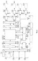
- items [1a - 1d] show the external sensing elements.
- Sensor drive circuits [2a - 2d] provide the bias signals for the sensors.
- Analog multiplexer [3] selects the signal from one of the sensing elements based on the selection data from the Central Control Unit [6] which is then converted to digital form by analog-to-digital converter [4].
- This digital output is adjusted for sensor linearity, offset and sensitivity by linearity, sensitivity and offset correction circuit [5] that receives the correction factor data in digital form from non-volatile memory [17].
- This corrected digital output is supplied to central control unit [6] which stores the data.
- Control input is received by means of external potentiometers [12a - 12c] and is used by the central control unit [6] alongwith the stored digital data received from the linearity, sensitivity and offset correction circuit [5] to generate the control signal for correcting the sensed parameter.
- This control signal is passed through digital filter [7] to remove noise and then applied to the input of digital demultiplexer [8] which routes it to one of the control latches [9a - 9f] under the control of the central control unit [6].
- the output of each control latch is connected to an output drive and protection circuit [10a - 10f].
- Each output drive and protection circuit drives an external switching device [11a - 11f] to actuate the relevant part of the appliance to correct the sensed parameter.
- the central control unit [6] drives a display drive unit [13] for displaying user input or sensed parameter value on an external display unit [14], and also an audio drive unit [15] for providing audio output through an external audio transducer [16].
- the central control unit [6] receives time-of-day data from real-time-clock unit [C] which enables it to perform control actions based on time-of-day requirements.
- a remote-control interface unit [R] connected to the said central control unit [6] provides the ability to receive user input data remotely form a hand-held remote control unit.
- a network interface unit [N] connects the said central control unit [6] to external devices, which may be other similar digital control units or other devices such as computers, and enables the exchange of data between the various devices in the network.
- a Clock Circuit [18] and non-volatile-memory [17] are connected to various points in the circuit as indicated.
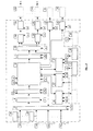
- Fig-2 the user variable inputs originate from external switches [20a - 20c], instead of potentiometers.
- Fig.-3 shows an implementation of the electronic control unit including the real-time clock, remote control interface unit and netwok interface unit and excluding the external blocks [1a-1d], [11a-11f], [12a-12c], [14], [16], [19], and [20a-20c] in the form of an Application Specific Integrated Circuit (ASIC) [21] to provide a solution that is both very miniature and cost-effective.
- ASIC Application Specific Integrated Circuit
- Fig-4 shows another embodiment using an ASIC [22] in which the non-volatile memory is external to the ASIC inorder to provide for larger storage capacity.
- a non-volatile memory interface block [23] is provided in the ASIC for connecting to the external non-volatile memory [24].
- Fig-5 shows the internal structure of each output drive and protection circuit.
- Overcurrent protection [25], over-heat protection [26] and over-voltage protection [27] circuits inside each output drive and protection circuit monitor the electrical conditions at the output of each external switching device [11a-11f] and limit or cut-off the drive to it in case of overload conditions.
- a soft-start drive circuit [28] provides a gradual start-up drive signal inorder to minimise stress on the external switching device [11a-11f] as well as the load (appliance).
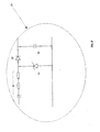
- Fig.-6 shows the transformerless power-supply [29] of 2 to 8 volts, used to provide power to the digital electronic control unit.
- a capacitive voltage dropping network [30], with a voltage clamping zener diode [31] reduces the input high-voltage A.C. voltage to a low value.
- This low value a.c. voltage is then rectified and filtered by a diode [32] and then filtered by a capacitor [33] to produce a low voltage d.c. supply that feeds power to the circuit.
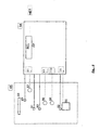
- Fig-7 shows an application of the electronic contol unit in a washing machine [34].
- a water level sensing element [35] placed inside the wash tank senses the water level in the tank
- a warmth sensing element [36] inside the wash tank senses the temperature of the water
- a detergent level sensing element [37] placed inside the detergent supply tank senses the detergent level.
- the water-fill valve [38], heating coil [39], detergent-fill valve [40], agitator motor [41], motor-reversing switch [42] and water-drain valve [43] are controlled by the electronic control unit [45] based on the signals received from the various sensing elements and from the user setting switches [44].
- a handheld remote-control unit [RC] is also used to control the user settings and receive status information, remotely.
- a real-time-clock [CL] on the front panel of the washing-machine displays time-of-day information and can be used to set control actions, e.g. turning-on or turning-off the washing-machine at programmed times during the day.
- a network [NW] connects the washing machine to other appliances in the home and to home computer (not shown), to provide computer controlled operation from within the home.
- Fig-8 shows an application of the electronic contol unit in a refrigerator [48].
- a temperature sensing element [49] placed inside the freezer compartment senses the temperature near the cooling coils [50]
- another temperature sensing element [51] placed inside the main compartment senses the temperature inside that compartment while a third temperature sensing element [52] senses the temperature of the compressor housing.
- a door switch [53] located on the door frame senses the open-close condition of the referigerator's door.
- the digital electronic control unit [54] receives the signals from each of these sensing elements and operates the compressor unit [55], circulating fan [56], refrigerator light [57] and door-open alarm [58] based on the signals received from each of the sensing elements and switches.
- the refrigerator has a real-time-clock [RCL] display on the front-panel [FP] that is used to display the time-of-day as well as to define control actions at programmed times of day.
- the network interface inside the digital electronic control unit is also used to connect the refrigerator to a network [NET] in the home that connects the various appliances to a central home computer (not shown) for monitoring and control.
- Sensing elements [1a - 1d] (which may be linear or non-linear transducers) are driven by sensor drive circuits [2a - 2d] and produce analog voltage signals in response to sensed parameters. These analog voltage signals are applied to the inputs of analog multiplexer [3].
- Analog multiplexer [3] outputs the signal from one of the sensing elements to analog-to-digital converter [4] under control of channel-select signals received from the central control unit [6].
- Analog-to-digital converter [4] produces a digital output that is the equivalent of the analog voltage supplied at its input.
- This digital output corresponding to the signal received from the selected sensing element is received by linearity and sensitivity and offset correction circuit [5] and modified by it, using data stored in non-volatile memory [17] at the time of manufacture of the digital electronic control unit, to correct for nonlinearities, offsets and sensitivity deviations in the sensing element's output. This produces a corrected, digital sensed parameter value.
- the central control unit and the linearity and sensitivity and offset correction circuit are digital logic circuits.
- the corrected sensed parameter value is stored by the central control unit [6] which receives these values for each of the sensing elements.
- the central control unit [6] also receives user-supplied inputs from potentiometers [12a - 12c] or switches [20a - 20c].
- the values of these inputs and the stored parameter values are evaluated by the central control unit [6] in accordance with control data that is supplied by the non-volatile memory [17].
- the result of the evaluation is in the form of a digital value that is output from the central control unit [6] to the input of the demultiplexer [7] alongwith selection signals that determine the output to which the result is routed.
- the sequence of evaluation is repeated for each output of the demultiplexer in a repetitive manner.
- central control unit [6] also outputs digital signals for driving the display drive unit [13] and audio drive unit [15] in accordance with control data supplied by non-volatile memory [17].
- the output from the demultiplexer is stored in one of the control latches [9a - 9f] based on the selection control signals generated by the central control unit [6], and is used to enable / disable the corresponding output drive and protection circuit [10a - 10f].
- Each output drive and protection circuit [10a - 10f] when enabled by its corresponding control latch [9a - 9f] generates the signals necessary to drive the external switching device [11a - 11f] inorder to actuate the relevant part of the appliance to correct the sensed parameter.
- the output drive and protection circuit [10a - 10f] also monitors the load conditions continuously and deactivates the drive to the external switching device [11a - 11f] if overload conditions are encountered.
- a real time clock unit [C] provides time-of-day input to the central control unit [6] for enabling control actions based on time-of-day values.
- a remote control interface unit [R] connected to the said central contrl unit [6] makes it possible for the user to input data remotely, instead of from the front panel of the digital control unit, with the help of a hand-held remote control device, which may be an infrared, ultrasonic or radio-frequency remote control transceiver.
- a network interface unit [N] connected to the said central control unit [6] provides the facility to connect the digital control unit to other devices, such as other similar digital control units or computers, inorder to exchange information.
- Clock Circuit [18] based on a quartz Crystal oscillator in the 32 KHz - 25 Mhz freaquency range generates all the timing signals necessary to operate each circuit block. while a Power Supply [19] supplies the necessary voltage and current to each circuit block of the electronic control unit.
- the present application includes the facilities for networking, remote control and time-of-day based control using a real-time clock.
Landscapes
- Engineering & Computer Science (AREA)
- Automation & Control Theory (AREA)
- General Engineering & Computer Science (AREA)
- Physics & Mathematics (AREA)
- General Physics & Mathematics (AREA)
- Computer Networks & Wireless Communication (AREA)
- Signal Processing (AREA)
- Selective Calling Equipment (AREA)
- Electrophonic Musical Instruments (AREA)
- Feedback Control In General (AREA)
- Polymers With Sulfur, Phosphorus Or Metals In The Main Chain (AREA)
- Control By Computers (AREA)
Abstract
Description
- a plurality of sensor drive circuits each of which drives an external sensing element, the said sensing elements converts the sensed parameter to an electrical signal,
- an analog multiplexer that receives the signal from each of the external sensing elements, and selectively routes one of the signal to its output,
- an analog-to-digital converter connected to the output of the said analog multiplexer, that converts the multiplexer output to digital form,
- a linearity, sensitivity and offset correction circuit connected to the output of the said analogue-to-digital converter for correcting the digital values received from it, using sensor calibration data stored in non-volatile memory,
- a central control unit that receives the corrected output from the said sensitivity offset and linearity correction circuit, and generates the control signals necessary for operation of the appliance, as well as the selection signals for controlling the said analog multiplexer, using control data supplied by the non-volatile memory,
- a digital noise filter connected to the output of the said central control unit, to eliminate spurious outputs,
- a digital de-multiplexer connected to the output of the said digital noise filter and controlled by the said central control unit for selecting the output to which the input from the said digital noise filter is to be connected,
- a plurality of control latches, each being connected at one output of the said digital de-multiplexer, for storing the digital data received from it and actuating the necessary part of the appliance in order to correct the sensed parameter,
- a non-volatile memory that stores the data and control parameters required for the operation of the said central control unit, linearity sensitivity and offset correction circuits, output drive and protection circuits.
- a clock oscillator that provides the timing signals necessary for
the operation of required circuits of the digital electronic control unit,
characterised in that the said central control unit is further connected to at least one of
the following at its input:
- a real-time clock that provides time-of-day data,
- a remote control interface unit, that provides the ability to receive user input and provide responses to the user from/to a remote control device,
- a network interface unit, that provides the capability for bidirectional transfer of data between the digital control unit and other devices.
Claims (20)
- A digital electronic control unit for controlling the functions of domestic and commercial appliances comprising:characterised in that,a plurality of sensor drive circuits (2a-2d) each of which drives an external sensing element (1a-1d), the said sensing elements (1a-1d) converts the sensed parameter to an electrical signal,an analog multiplexer (3) that receives the signal from each of the external sensing elements (1a-1d), and selectively routes one of the signal to its output,an analog-to-digital converter (4) connected to the output of the said analog multiplexer (3), that converts the multiplexer output to digital form,a linearity, sensitivity and offset correction circuit (5) connected to the output of the said analogue-to-digital converter (4) for correcting the digital values received from it, using sensor calibration data stored in a non-volatile memory (17),a central control unit (6) that receives the corrected output from the said linearity, sensitivity and offset correction circuit (5), and generates the control signals necessary for operation of an appliance, as well as the selection signals for controlling the said analog multiplexer (3), using control data supplied by the non-volatile memory (17),a digital noise filter (7) connected to the output of the said central control unit (6) to eliminate spurious outputs,a digital de-multiplexer (8) connected to the output of the said digital noise filter (7) and controlled by the said central control unit (6) for selecting the output to which the input from the said digital noise filter is to be connected,a plurality of control latches (9a-9f), each being connected at one output of the said digital de-multiplexer (8), for storing the digital data received from it and actuating the necessary part of the appliance in order to correct the sensed parameter,a non-volatile memory (17) that stores the data and control parameters required for the operation of the said central control unit (6), linearity sensitivity and offset correction circuits (5), output drive and protection circuits (10a-10f),a clock oscillator (18) that provides the timing signals necessary for the operation of required circuits of the digital electronic control unit,the said central control unit (6) is further connected to at least one of the following at its input:a real-time clock (C) that provides time-of-day data,a remote control interface unit (R), that provides the ability to receive user input and provide responses to the user from/to a remote control device,a network interface unit (N), that provides the capability for bidirectional transfer of data between the digital control unit and other devices.
- A digital electronic control unit as claimed in claim 1 characterised in that said remote control interface unit (R) is an infra-red or ultrasonic or radio frequency remote interface units.
- A digital electronic control unit as claimed in claim 1 characterised in that said remote control interface unit (R) is a radio-frequency remote interface unit.
- A digital electronic control unit as claimed in claim 1 characterised in that said remote control interface unit (R) is an ultrasonic remote interface unit.
- A digital electronic control unit as claimed in claim 1 characterised in that said network interface unit (N) is for a Transport Control Protocol/Internet Protocol (TCP/IP) based network such as for Internet connectivity.
- A digital electronic control unit as claimed in claim 1 characterised in that said network interface unit (N) is for a Controller Area Network (CAN) Bus based network.
- A digital electronic control unit as claimed in claim 1 characterised in that said network interface unit (N) is for a cable network.
- A digital electronic control unit as claimed in claim 1 characterised in that said sensing element (1a-1d) are linear or non-linear transducers.
- A digital electronic control unit as claimed in claim 1 characterised in that said central control unit (6) and the said linearity, sensitivity and offset correction circuit 5 are digital logical circuits.
- A digital electronic control unit as claimed in claim 1 characterised in that the output of each of the said control latches (9a-9f) is connected to the output drive and protection circuit (10a-10f) to drive an external switching device (11a-11f) to actuate the necessary part of the appliance in order to correct the sensed parameter.
- A digital electronic control unit as claimed in claim 1 characterised in that to provide user-defined inputs and selections for defining the desired values of the control parameters, a plurality of user input means are connected to the said central control unit (6) through said analog multiplexer (3), analog-to-digital converter (4), and linearity, sensitivity and offset correction unit (5).
- A digital electronic control unit as claimed in claim 11 characterised in that the user variable means are potentiometers or switches (12a-12c, 20a-20c).
- A digital electronic control unit as claimed in claim 11 characterised in that a display drive unit (13) is connected to the output of the said central control unit (6) for the selective display of either the sensed parameter or the user-specified value from the user input means on an external display device (14).
- A digital electronic control unit as claimed in claim 1 characterised in that an audio drive unit (15) is connected to the output of the said central control unit (6) for generating audio signals for user's attention using an external audio transducer (16).
- A digital electronic control unit as claimed in claim 1 characterised in that power supply (29) for powering the digital electronic control unit consists of a low loss capacitive voltage dropping network (30) followed by a voltage clamping device (31), a rectifier and a fitter network (32, 33) to provide a DC voltage.
- A digital electronic control unit as claimed in any of the preceding claims characterised in that entire digital electronic control unit including the real-time clock (R), remote control interface unit (R) and network interface unit (N) except power supply, sensing elements, user variable means and external switching devices, is implemented as a custom Application Specific Integrated Circuit (ASIC) (22), to provide a miniature and cost effective control element.
- A digital electronic control unit as claimed in claim 16 characterised in that the ASIC also excludes non-volatile memory in order to provide larger capacities for storage of data, but includes a memory interface block (23) for connecting to an external non-volatile memory (24).
- A digital electronic control unit as claimed in claim 10 characterised in that output drive and protection circuit (10a-10f) includes a thermal protection circuit (26), an over-current protection circuit (25), over-voltage (27) protection circuit and a soft start circuit (28) for providing an effective reduced voltage start up to the load during the initial period of turn-on.
- A digital electronic control unit as claimed in claim 1 characterised in that frequency of the clock oscillator (18) ranges from 32 KHz - 25 MHz.
- A digital electronic control unit as claimed in claim 19 characterised in that frequency of the clock oscillator (18) is preferably 4 MHz.
Applications Claiming Priority (1)
| Application Number | Priority Date | Filing Date | Title |
|---|---|---|---|
| PCT/IN1999/000031 WO2001006335A1 (en) | 1999-07-16 | 1999-07-16 | Digital electronic control unit |
Publications (2)
| Publication Number | Publication Date |
|---|---|
| EP1114362A1 EP1114362A1 (en) | 2001-07-11 |
| EP1114362B1 true EP1114362B1 (en) | 2005-03-23 |
Family
ID=11076664
Family Applications (1)
| Application Number | Title | Priority Date | Filing Date |
|---|---|---|---|
| EP99935043A Expired - Lifetime EP1114362B1 (en) | 1999-07-16 | 1999-07-16 | Digital electronic control unit |
Country Status (11)
| Country | Link |
|---|---|
| EP (1) | EP1114362B1 (en) |
| JP (1) | JP2003501772A (en) |
| KR (1) | KR20010106106A (en) |
| CN (1) | CN1318162A (en) |
| AT (1) | ATE291753T1 (en) |
| AU (1) | AU5064099A (en) |
| BR (1) | BR9909082A (en) |
| CA (1) | CA2323065A1 (en) |
| DE (1) | DE69924393T2 (en) |
| GB (1) | GB2358486A (en) |
| WO (1) | WO2001006335A1 (en) |
Families Citing this family (6)
| Publication number | Priority date | Publication date | Assignee | Title |
|---|---|---|---|---|
| DE69923335T2 (en) | 1999-07-05 | 2006-01-12 | Vasu Tech Ltd. | Digital electrical control unit for household and commercial applications |
| US7464426B2 (en) | 2001-07-04 | 2008-12-16 | Lg Electronics Inc. | Internet-washer and operating method thereof |
| CN100464501C (en) * | 2006-09-12 | 2009-02-25 | 北京中星微电子有限公司 | Method and device for removing burrs in signal |
| RU2010147670A (en) | 2008-04-23 | 2012-05-27 | Конинклейке Филипс Электроникс Н.В. (Nl) | LIGHTED DEVICE WITH IMPROVED REMOTE CONTROL |
| US7816907B2 (en) * | 2008-04-23 | 2010-10-19 | Lantiq Deutschland Gmbh | Integrated circuit with a measuring circuit and method of configuring an integrated circuit with a measuring circuit |
| CN109140703A (en) * | 2018-08-18 | 2019-01-04 | 北京米微环保科技有限公司 | A kind of fresh air system |
Citations (2)
| Publication number | Priority date | Publication date | Assignee | Title |
|---|---|---|---|---|
| WO1998020615A2 (en) * | 1996-10-21 | 1998-05-14 | Electronics Development Corporation | Smart sensor module |
| EP0924588A1 (en) * | 1997-10-16 | 1999-06-23 | Varma, Dhruv | Electronic thermostat control unit and its use in multipoint temperature controller for refrigeration and heating systems |
Family Cites Families (7)
| Publication number | Priority date | Publication date | Assignee | Title |
|---|---|---|---|---|
| US4298946A (en) * | 1978-12-18 | 1981-11-03 | Texas Instruments Incorporated | Electronically controlled programmable digital thermostat |
| US4836442A (en) * | 1988-12-14 | 1989-06-06 | Honeywell Inc. | Compensation circuit for sensor lag to reduce undershoot and overshoot |
| US5423192A (en) * | 1993-08-18 | 1995-06-13 | General Electric Company | Electronically commutated motor for driving a compressor |
| CA2069273A1 (en) * | 1992-05-22 | 1993-11-23 | Edward L. Ratcliffe | Energy management systems |
| US5412782A (en) * | 1992-07-02 | 1995-05-02 | 3Com Corporation | Programmed I/O ethernet adapter with early interrupts for accelerating data transfer |
| US5889949A (en) * | 1996-10-11 | 1999-03-30 | C-Cube Microsystems | Processing system with memory arbitrating between memory access requests in a set top box |
| US5920699A (en) * | 1996-11-07 | 1999-07-06 | Hewlett-Packard Company | Broadcast isolation and level 3 network switch |
-
1999
- 1999-07-16 CA CA002323065A patent/CA2323065A1/en not_active Abandoned
- 1999-07-16 AT AT99935043T patent/ATE291753T1/en not_active IP Right Cessation
- 1999-07-16 KR KR1020007011863A patent/KR20010106106A/en not_active Application Discontinuation
- 1999-07-16 WO PCT/IN1999/000031 patent/WO2001006335A1/en active IP Right Grant
- 1999-07-16 BR BR9909082-1A patent/BR9909082A/en not_active IP Right Cessation
- 1999-07-16 AU AU50640/99A patent/AU5064099A/en not_active Abandoned
- 1999-07-16 CN CN99811001A patent/CN1318162A/en active Pending
- 1999-07-16 DE DE69924393T patent/DE69924393T2/en not_active Expired - Fee Related
- 1999-07-16 JP JP2001502645A patent/JP2003501772A/en active Pending
- 1999-07-16 GB GB0022076A patent/GB2358486A/en not_active Withdrawn
- 1999-07-16 EP EP99935043A patent/EP1114362B1/en not_active Expired - Lifetime
Patent Citations (3)
| Publication number | Priority date | Publication date | Assignee | Title |
|---|---|---|---|---|
| WO1998020615A2 (en) * | 1996-10-21 | 1998-05-14 | Electronics Development Corporation | Smart sensor module |
| EP0924588A1 (en) * | 1997-10-16 | 1999-06-23 | Varma, Dhruv | Electronic thermostat control unit and its use in multipoint temperature controller for refrigeration and heating systems |
| EP0927919A1 (en) * | 1997-10-16 | 1999-07-07 | Varma Trafag Limited | Electronic thermostat control unit and its use in multipoint temperature controller for refrigeration and heating systems |
Also Published As
| Publication number | Publication date |
|---|---|
| DE69924393D1 (en) | 2005-04-28 |
| KR20010106106A (en) | 2001-11-29 |
| EP1114362A1 (en) | 2001-07-11 |
| CN1318162A (en) | 2001-10-17 |
| AU5064099A (en) | 2001-02-05 |
| CA2323065A1 (en) | 2001-01-16 |
| BR9909082A (en) | 2001-11-06 |
| WO2001006335A1 (en) | 2001-01-25 |
| GB0022076D0 (en) | 2000-10-25 |
| GB2358486A (en) | 2001-07-25 |
| DE69924393T2 (en) | 2006-03-09 |
| ATE291753T1 (en) | 2005-04-15 |
| JP2003501772A (en) | 2003-01-14 |
Similar Documents
| Publication | Publication Date | Title |
|---|---|---|
| US6549866B1 (en) | Digital electronic control unit | |
| TW508589B (en) | Configurable electronic controller for appliances | |
| KR100695773B1 (en) | Electronic controller for appliances | |
| EP1095440B1 (en) | System and method for monitoring a plurality of electric users, particularly household appliances | |
| AU778335B2 (en) | Multipoint digital temperature controller | |
| US20100152904A1 (en) | Refrigerator having user-controlled functions | |
| KR100496917B1 (en) | Combined appliance | |
| EP1114362B1 (en) | Digital electronic control unit | |
| EP2302605A1 (en) | Assembly and method for monitoring a set of household appliances | |
| KR100385185B1 (en) | Home netwok system and controlling method using a refrigerator | |
| MXPA00008637A (en) | Digital electronic control unit | |
| KR100405278B1 (en) | The Recessed Type Concent for reclamation timer and that control means | |
| KR100604988B1 (en) | A switching device for remote control | |
| GB2339500A (en) | Control of domestic appliances | |
| KR100215033B1 (en) | Air conditioner | |
| JP2002218562A (en) | Power supply control system | |
| WO2000036480A1 (en) | Improved control and monitoring apparatus for refrigerating appliances | |
| WO1997000508A1 (en) | Control for power supply | |
| ZA200502064B (en) | Electrical circuit device |
Legal Events
| Date | Code | Title | Description |
|---|---|---|---|
| PUAI | Public reference made under article 153(3) epc to a published international application that has entered the european phase |
Free format text: ORIGINAL CODE: 0009012 |
|
| 17P | Request for examination filed |
Effective date: 20010417 |
|
| AK | Designated contracting states |
Kind code of ref document: A1 Designated state(s): AT BE CH CY DE DK ES FI FR GB GR IE IT LI LU MC NL PT SE |
|
| 17Q | First examination report despatched |
Effective date: 20030819 |
|
| GRAP | Despatch of communication of intention to grant a patent |
Free format text: ORIGINAL CODE: EPIDOSNIGR1 |
|
| GRAS | Grant fee paid |
Free format text: ORIGINAL CODE: EPIDOSNIGR3 |
|
| GRAA | (expected) grant |
Free format text: ORIGINAL CODE: 0009210 |
|
| AK | Designated contracting states |
Kind code of ref document: B1 Designated state(s): AT BE CH CY DE DK ES FI FR GB GR IE IT LI LU MC NL PT SE |
|
| PG25 | Lapsed in a contracting state [announced via postgrant information from national office to epo] |
Ref country code: NL Free format text: LAPSE BECAUSE OF FAILURE TO SUBMIT A TRANSLATION OF THE DESCRIPTION OR TO PAY THE FEE WITHIN THE PRESCRIBED TIME-LIMIT Effective date: 20050323 Ref country code: FI Free format text: LAPSE BECAUSE OF FAILURE TO SUBMIT A TRANSLATION OF THE DESCRIPTION OR TO PAY THE FEE WITHIN THE PRESCRIBED TIME-LIMIT Effective date: 20050323 Ref country code: BE Free format text: LAPSE BECAUSE OF FAILURE TO SUBMIT A TRANSLATION OF THE DESCRIPTION OR TO PAY THE FEE WITHIN THE PRESCRIBED TIME-LIMIT Effective date: 20050323 Ref country code: AT Free format text: LAPSE BECAUSE OF FAILURE TO SUBMIT A TRANSLATION OF THE DESCRIPTION OR TO PAY THE FEE WITHIN THE PRESCRIBED TIME-LIMIT Effective date: 20050323 |
|
| REG | Reference to a national code |
Ref country code: GB Ref legal event code: FG4D |
|
| REG | Reference to a national code |
Ref country code: CH Ref legal event code: EP |
|
| REG | Reference to a national code |
Ref country code: IE Ref legal event code: FG4D |
|
| REF | Corresponds to: |
Ref document number: 69924393 Country of ref document: DE Date of ref document: 20050428 Kind code of ref document: P |
|
| PG25 | Lapsed in a contracting state [announced via postgrant information from national office to epo] |
Ref country code: GR Free format text: LAPSE BECAUSE OF FAILURE TO SUBMIT A TRANSLATION OF THE DESCRIPTION OR TO PAY THE FEE WITHIN THE PRESCRIBED TIME-LIMIT Effective date: 20050623 Ref country code: DK Free format text: LAPSE BECAUSE OF FAILURE TO SUBMIT A TRANSLATION OF THE DESCRIPTION OR TO PAY THE FEE WITHIN THE PRESCRIBED TIME-LIMIT Effective date: 20050623 |
|
| PG25 | Lapsed in a contracting state [announced via postgrant information from national office to epo] |
Ref country code: ES Free format text: LAPSE BECAUSE OF FAILURE TO SUBMIT A TRANSLATION OF THE DESCRIPTION OR TO PAY THE FEE WITHIN THE PRESCRIBED TIME-LIMIT Effective date: 20050704 |
|
| PG25 | Lapsed in a contracting state [announced via postgrant information from national office to epo] |
Ref country code: LU Free format text: LAPSE BECAUSE OF NON-PAYMENT OF DUE FEES Effective date: 20050716 Ref country code: CY Free format text: LAPSE BECAUSE OF FAILURE TO SUBMIT A TRANSLATION OF THE DESCRIPTION OR TO PAY THE FEE WITHIN THE PRESCRIBED TIME-LIMIT Effective date: 20050716 |
|
| PG25 | Lapsed in a contracting state [announced via postgrant information from national office to epo] |
Ref country code: IE Free format text: LAPSE BECAUSE OF NON-PAYMENT OF DUE FEES Effective date: 20050718 |
|
| PG25 | Lapsed in a contracting state [announced via postgrant information from national office to epo] |
Ref country code: MC Free format text: LAPSE BECAUSE OF NON-PAYMENT OF DUE FEES Effective date: 20050731 |
|
| PGFP | Annual fee paid to national office [announced via postgrant information from national office to epo] |
Ref country code: GB Payment date: 20050830 Year of fee payment: 7 |
|
| REG | Reference to a national code |
Ref country code: CH Ref legal event code: NV Representative=s name: KIRKER & CIE SA |
|
| NLV1 | Nl: lapsed or annulled due to failure to fulfill the requirements of art. 29p and 29m of the patents act | ||
| PG25 | Lapsed in a contracting state [announced via postgrant information from national office to epo] |
Ref country code: PT Free format text: LAPSE BECAUSE OF FAILURE TO SUBMIT A TRANSLATION OF THE DESCRIPTION OR TO PAY THE FEE WITHIN THE PRESCRIBED TIME-LIMIT Effective date: 20050907 |
|
| PGFP | Annual fee paid to national office [announced via postgrant information from national office to epo] |
Ref country code: CH Payment date: 20051229 Year of fee payment: 7 |
|
| PLBE | No opposition filed within time limit |
Free format text: ORIGINAL CODE: 0009261 |
|
| STAA | Information on the status of an ep patent application or granted ep patent |
Free format text: STATUS: NO OPPOSITION FILED WITHIN TIME LIMIT |
|
| 26N | No opposition filed |
Effective date: 20051227 |
|
| REG | Reference to a national code |
Ref country code: IE Ref legal event code: MM4A |
|
| EN | Fr: translation not filed | ||
| PG25 | Lapsed in a contracting state [announced via postgrant information from national office to epo] |
Ref country code: GB Free format text: LAPSE BECAUSE OF NON-PAYMENT OF DUE FEES Effective date: 20060716 |
|
| PG25 | Lapsed in a contracting state [announced via postgrant information from national office to epo] |
Ref country code: LI Free format text: LAPSE BECAUSE OF NON-PAYMENT OF DUE FEES Effective date: 20060731 Ref country code: CH Free format text: LAPSE BECAUSE OF NON-PAYMENT OF DUE FEES Effective date: 20060731 |
|
| PGFP | Annual fee paid to national office [announced via postgrant information from national office to epo] |
Ref country code: IT Payment date: 20060731 Year of fee payment: 8 |
|
| PGFP | Annual fee paid to national office [announced via postgrant information from national office to epo] |
Ref country code: DE Payment date: 20070131 Year of fee payment: 8 |
|
| REG | Reference to a national code |
Ref country code: CH Ref legal event code: PL |
|
| GBPC | Gb: european patent ceased through non-payment of renewal fee |
Effective date: 20060716 |
|
| PG25 | Lapsed in a contracting state [announced via postgrant information from national office to epo] |
Ref country code: SE Free format text: LAPSE BECAUSE OF FAILURE TO SUBMIT A TRANSLATION OF THE DESCRIPTION OR TO PAY THE FEE WITHIN THE PRESCRIBED TIME-LIMIT Effective date: 20050623 |
|
| PG25 | Lapsed in a contracting state [announced via postgrant information from national office to epo] |
Ref country code: DE Free format text: LAPSE BECAUSE OF NON-PAYMENT OF DUE FEES Effective date: 20080201 |
|
| PGFP | Annual fee paid to national office [announced via postgrant information from national office to epo] |
Ref country code: FR Payment date: 20070731 Year of fee payment: 9 |
|
| PG25 | Lapsed in a contracting state [announced via postgrant information from national office to epo] |
Ref country code: IT Free format text: LAPSE BECAUSE OF NON-PAYMENT OF DUE FEES Effective date: 20070716 |
|
| PG25 | Lapsed in a contracting state [announced via postgrant information from national office to epo] |
Ref country code: FR Free format text: LAPSE BECAUSE OF NON-PAYMENT OF DUE FEES Effective date: 20080730 |