BACKGROUND OF THE INVENTION
This invention relates to a component for a rotating electrical machine and more
particularly to an improved arrangement for forming the windings and electrical connections
for a component that cooperates with relatively rotatable permanent magnets for machine
operation.
In most rotating electrical equipment, there is either a rotating or fixed element that
comprises a core having a plurality of teeth around which individual windings are wound.
Frequently, these windings are positioned on bobbins that surround the core teeth and which
are electrically non-conductive.
In order to provide electrical connections for either delivery of electrical power to these
windings, if the machine is a motor, or transmission of electrical power from the windings, if it
is a generator, it is necessary to provide connections between respective winding coils and
terminals of outside conductors. Normally these connections are made by soldered
connections between the terminal ends and the core winding ends.
These connections are frequently bunched between the adjacent coils and thus, limit the
available space and tend to make the machine larger than necessary. In addition, the formation
of these soldered joints requires considerable labor and time and adds significantly to the
expense of the machine. In addition, the use of the separate soldered connections also raises
the possibility of poor connections or connections that can become easily broken. Furthermore,
it is necessary to provide the external connection wires to be fastened to the core by some
external fastening means such as screws or the like.
It is, therefore, a principal object to this invention to provide an improved component
for an electrical machine having wound coils that eliminate the necessity for soldered
connections.
It is a further object to this invention to provide an improved component of this type for
a rotating electrical machine wherein the size can be kept more compact and the efficiency of
the machine significantly improved.
It is a further object to this invention to provide an improved coil winding arrangement
for a rotating machine wherein the electrical connections are simplified and can be made
without necessitating considerable hand labor.
SUMMARY OF THE INVENTION
This invention is adapted to be embodied in a component of a rotating electrical
machine that is comprised of a plurality of coil windings each wound on the pole teeth of a core
through a bobbin. The bobbin has portions that surround the pole teeth of the core and around
which the conductors of the coils are wound. The bobbin carries a plurality of wiring
conductors and each has one end connected to at least one of the coil ends and the other end
connected to one external connection terminal.
BRIEF DESCRIPTION OF THE DRAWINGS
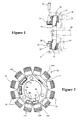
Figure 1 is a cross sectional view taken through a rotating electrical machine
constructed in accordance with an embodiment of the invention and showing, in this
embodiment, the stator in cross-section and solid lines with the remaining components of the
machine being shown in phantom. This view is taken generally along the line 1-0-5 of Fig. 4.
Fig. 2 is a front view of the stator.
Fig. 3 is a perspective view of the stator core.
Fig. 4 is a front view of the stator coils showing the winding direction
thereof.
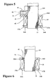
Fig. 5 is an enlarged cross sectional view taken along the line O-5 of Fig. 4.
Fig. 6 is an enlarged cross section along line O-6 of Fig. 4.
Fig. 7 is a front view of one of the bobbin halves.
Fig. 8 is a view looking in the same direction as Fig. 7 showing the
arrangement of the inserted wiring conductors in solid lines with the body of the
bobbin half shown in phantom.
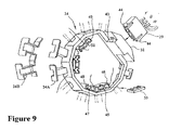
Fig. 9 is an exploded perspective view of the bobbin half shown in Figs. 7
and 8 and showing the relation to the associated electrical connectors or terminals
and the other bobbin half that is shown broken away.
Fig. 10 is an exploded front view of one of the external conncctions and
associated electrical connector shown in Fig. 9.
Fig. I 1 is a perspective view of the components shown in Fig. 10 in the coupled
state.
Fig. 12. is a cross sectional view showing the first step coupling movement of
the external connection terminal and its associated electrical connector shown in
Figs. 10 and 11.
Fig. 13. is a cross sectional view, in part similar to Figure 12, showing the
completion of the electrical connection
DETAILED DESCRIPTION OF THE PREFERRED EMBODIMENT
Referring first to Fig. 1, a rotating electrical machine constructed in accordance with an
embodiment of the invention is identified generally by the reference numeral 21. This
invention deals primarily with the coil windings and terminal connections of this machine 21,
which, in this embodiment, is embodied in a stator 22 having a plurality, namely 12, of pole
pieces or cores 23 and associated bobbins of a bobbin assembly 24 on which coil windings 25
are wound, in a manner to be described.
In this particular embodiment of the machine, the stator 22 is fixed against rotation in
any suitable manner. The stator 22 cooperates with a rotating cup-shape member 26 that carries
a plurality of circumferentially spaced permanent magnets 27. This cup-shape member 26 is
affixed for rotation with a shaft 28.
By way of example, the rotating machine 21 may comprise an electrical generator
wherein a voltage is induced in the coil windings 25 upon rotation of the magnets 27 to provide
electrical current output. Alternatively, the mechanism may comprise an electric motor as will
become apparent to those skilled in the art. Also, although the invention is described in
conjunction with a stator, certain facets of the invention may also be employed where the rotor
carries the coil windings.
From the description of the problem of the prior art contained in the "Background Of
The Invention" section of the specification, it should be apparent that the invention deals
primarily with the manner in which the windings 25 are associated with the cores 23 and the
electrical connections thereto. One of the male electrical connectors for the external electrical
connection appears in Fig. 1 and is identified generally by the reference numeral 29. This male
electrical connector 29 cooperates with a female external terminal or connector 31 formed on
the stator 22 around an annular opening 32 formed therein, which a portion of the shaft 28
passes.
Referring now primarily to Fig. 3, the core 23 is formed of a laminated construction
consisting of silicon or carbon steel plates laminated with insulating layers. This forms the
plurality of cores or pole pieces 23, certain of which are numbered alphabetically, that extend
outwardly from a hub portion 34. Each of the pole pieces 23 has an enlarged headed portion.
As may be best seen in the cross-sectional views of Figs. 5 and 6, the bobbin assembly,
indicated generally by the reference numeral 24 is associated with the cores 23 and is formed
from a pair of mating pieces or halves 24A and 24B. The bobbin halves 24A and 24B are
snugly received around the pole pieces 23 and each has a pair of flanges 36 and 37 around
which the individual coil windings 25 are wound in a manner which will be described. The
bobbin halves 24A and 24B are made from a suitable insulating resin by injection molding.
During this molding process, a number of conductors, which may be formed from
stamped metallic pieces, are embedded in one or both of the bobbin halves 24A and 24B. In
the illustrated embodiment, all of these conductors are mounted in a side enlargement of the
bobbin half 24A and these conductors appear best in Fig. 8.
The conductors, indicated generally by the reference numerals 39, 41 and 42, have
common output terminals that lie in side by side relationship as best seen in Figure 3 and which
form terminal ends Y, B and W, designated as color coding of the individual conductors 39, 41
and 42, respectively. The conductors 39, 41 and 42 are formed preferably as stamped blanks of
a highly conductive material such as copper. Opposite ends of these conductors 39, 41 and 42
are associated with certain of the coil windings 25 in a manner to be described so as to simplify
the connections thereto and the entire electrical structure and to avoid the necessity of having
soldered connections.
The external female communication terminal 31 encircles the terminal ends Y, B and
W of the individual conductors 39, 41 and 42 so as to receive the connector 29 when pressed
together in a radial direction and form the desired electrical connections. This construction
appears best in Figs. 1, 2 and 9 through 13.
As may be seen, particularly from these latter four figures, the bobbin half 24A is
formed with a pair of openings 43 that receive tabs 44 formed on the external female connector
29. This provides a snap together connection being made as seen in these three figures. Wires
Y, B and W are carried by the connector 29 and cooperate with the terminal ends of the
corresponding designation. Thus, electrically power can be extracted through these conductors.
This external female terminal 31 is formed adjacent a pole piece indicated at 23A.
The conductor 41 extends from its terminal end B in a clockwise direction around the
bobbin half 24A and terminates adjacent the fifth pole (23B) counting in a clockwise direction
from the pole 23A at a terminal 45. This terminal 45 extends up to the base of the magnetic
pole 23B and terminates in a further female electrical connector 46 formed in the bobbin half
24A and integrally with it. In a similar manner, the conductor 42 extends circumferentially
around from the first pole 23A past the fifth pole 23B to the sixth pole 23C where it forms a
terminal end 47. This terminal end 47 terminates in a further female electrical connector 48
formed integrally with the bobbin half 24A.
Finally, the conductor 39 extends in a counter clockwise direction from the terminal
end Y to a terminal end formed adjacent the tenth pole 23D at a terminal end 49. This terminal
end 49 extends to the base of the core 23D and terminates in a female external electrical
connector 51.
Between the terminal female connectors 48 and 51 there is formed a further housing
portion 52. In the illustrated embodiment, this housing portion 52 serves no purpose. However,
it can be utilized in other embodiments as an electrical connector where other winding
arrangements in addition to those, which will be described shortly, are employed.
Referring now primarily to Fig. 4, in the illustrated embodiment the twelve poles 23
and their associated windings 25 are formed in two groups, the first consisting of a winding N1
which begins at the terminal end 47 where it is connected by means of inserting it into an
opening formed in a tip of the terminal end 47 thus avoiding the necessity for soldering. This
winding is then wound around the sixth pole 23C and specifically the portion of the bobbin 24
that is associated with it and then without interruption wound around the next three poles 23
and terminates at a conductor terminal found at the base of the eleventh pole 23D in the
electrical connector 49. These ends are seen in Fig. 4.
In a similar manner, a second winding N2 begins at a terminal formed in the electrical
connector 51 and is wound around the eleventh pole 23D and more specifically its bobbin and
the succeeding eight poles traveling in the clockwise direction to terminate at the pole 23B
where it terminates in the electrical connector 46.
Thus, it should be readily seen that there are no soldered connections and the windings
can extend continuously around the stator and have their connections to the terminals formed in
the housings 51, 48 and 45. It will be seen that the housing pieces 46 and 48 have two
conductor receiving openings while the housing portion 51 has three openings. These
openings bridge the respective conductors to which the coil ends are affixed and receive
coupling devices 53, in the case of the two- terminal openings 46 and 48, and 54, in the case of
the three-opening housing 51. These connectors 53 and 54 have internal wiring that form the
completion of the circuits between the coil ends so as to further simplify the overall wiring and
again avoid soldered terminals.
Therefore, it should be readily apparent that the described construction provides a very
compact coil winding arrangement for a rotating machine and one in which no soldered
connections are required. Also, because of the good electrical connections the power loses are
minimized and the efficiency of the device significantly improves. In addition, because there
are no soldered connections, the likelihood of failure of the connections is substantially
reduced and hence, the life of the associated machine can be prolonged while continuing to
maintain a good power output or efficiency depending upon whether the device operates as a
generator or a motor.
Of course, the foregoing description is that of a preferred embodiment of the invention
and various changes and modifications may be made without departing from the spirit and
scope of the invention, as defined by the appended claims.
An electrical machine having a plurality of pole pieces surrounded by bobbins and
upon which individual coil windings are formed. The bobbins are formed by a insulating
material in which are embedded electrical connectors that have terminal ends that afford
connection to the coil windings and to an external connection for either deriving electrical
power in the case the machine operates as a generator or receiving power in the event the
device operates as a motor. Thus, cost is reduced and at the same time the device is more
compact and more efficiency.