EP1103102B1 - Improved interleavers for turbo code - Google Patents
Improved interleavers for turbo code Download PDFInfo
- Publication number
- EP1103102B1 EP1103102B1 EP99931422A EP99931422A EP1103102B1 EP 1103102 B1 EP1103102 B1 EP 1103102B1 EP 99931422 A EP99931422 A EP 99931422A EP 99931422 A EP99931422 A EP 99931422A EP 1103102 B1 EP1103102 B1 EP 1103102B1
- Authority
- EP
- European Patent Office
- Prior art keywords
- size
- predetermined
- portions
- data frame
- permuting
- Prior art date
- Legal status (The legal status is an assumption and is not a legal conclusion. Google has not performed a legal analysis and makes no representation as to the accuracy of the status listed.)
- Expired - Lifetime
Links
Images

Classifications
-
- H—ELECTRICITY
- H03—ELECTRONIC CIRCUITRY
- H03M—CODING; DECODING; CODE CONVERSION IN GENERAL
- H03M13/00—Coding, decoding or code conversion, for error detection or error correction; Coding theory basic assumptions; Coding bounds; Error probability evaluation methods; Channel models; Simulation or testing of codes
- H03M13/27—Coding, decoding or code conversion, for error detection or error correction; Coding theory basic assumptions; Coding bounds; Error probability evaluation methods; Channel models; Simulation or testing of codes using interleaving techniques
- H03M13/2771—Internal interleaver for turbo codes
-
- H—ELECTRICITY
- H03—ELECTRONIC CIRCUITRY
- H03M—CODING; DECODING; CODE CONVERSION IN GENERAL
- H03M13/00—Coding, decoding or code conversion, for error detection or error correction; Coding theory basic assumptions; Coding bounds; Error probability evaluation methods; Channel models; Simulation or testing of codes
- H03M13/27—Coding, decoding or code conversion, for error detection or error correction; Coding theory basic assumptions; Coding bounds; Error probability evaluation methods; Channel models; Simulation or testing of codes using interleaving techniques
- H03M13/2735—Interleaver using powers of a primitive element, e.g. Galois field [GF] interleaver
Definitions
- This invention relates to the field of electronic communications systems and, more particularly, to interleavers for performing code modulation.
- Turbo coded modulation has proven to be a practical, power-efficient, and bandwidth-efficient modulation method for "random-error" channels characterized by additive white Gaussian noise (AWGN) or fading. These random-error channels can be found, for example, in the code division multiple access (CDMA) environment.
- AWGN additive white Gaussian noise
- CDMA code division multiple access
- turbo codes The key innovation of turbo codes is an interleaver which permutes the original received or transmitted data frame before input to a second encoder. Performing is accomplished by a processor performing a randomizing algorithm, the construction of which is well known. Combining the permuted data frames with the original data frames has shown to achieve low bit-error rates in AWGN and fading channels.
- the interleaving process increases the diversity in the data in such a way that if the modulated symbol is distorted in transmission the error may be recoverable with the use of error correcting algorithms in the decoder.
- a conventional interleaver collects, or frames, the signal points to be transmitted into a matrix, where the matrix is sequentially filled up a row at a time. After a predefined number of signal points have been framed, the interleaver is emptied by sequentially reading out the columns of the matrix for transmission. As a result, signal points in the same row of the matrix that were near each other in the original signal point flow are separated by a number of signal points equal to the number of rows in the matrix. Ideally, the number of columns and rows would be pricked such that interdependent signal points, after transmission, would be separated by more than the expected length of an error burst for the channel. However, this may not be practicable.
- uniform interleaving i.e. a regular interleaving pattern
- non-uniform interleaving i.e. a pseudo-irregular interleaving pattern.
- FC finite code words
- non-uniform interleaving i.e. a pseudo-irregular interleaving pattern.
- uniform interleaving finite code words (FC) of higher weight can be constructed from FCs of lower weight. Therefore a certain "repetitive pattern" of low-weight FC output sequences can occur in the output stream of a uniform-interleaving turbo coder.
- uniform interleaving does not sufficiently de-correlate the output of the two encoders, hence the minimum distance of the resulting turbo code does not increase as one might expect.
- non-uniform interleaving achieves better "maximum scattering" of data and "maximum disorder” of the output sequence, which means that the redundancy introduced by the two convolutional codes is more equally spread in the output sequence of the turbo encoder.
- the minimum distance is increased to much higher values than for uniform interleaving.
- a persistent problem for non-uniform interleaving is how to achieve sufficient "'non-uniformity", since the interleaving algorithms can only be based on pseudo-irregular patterns. Besides this, the effort for implementing the scheme should be reasonable for practical applications.
- conventional interleavers require a significant amount of memory in the encoder.
- Conventional interleaving matrices also require delay compensations, which limit their use for applications with real-time requirements.
- the present invention interleaves a data frame, where the data frame has a predetermined size and is made up of portions.
- An embodiment of the invention includes a memory configured to receive and store the data frame. Once received, the data frame is indexed by a plurality of rows having a predetermined row size and a plurality of columns having a predetermined column size. The product of the predetermined row size and the predetermined column size equals the predetermined size of the data frame.
- a processor is coupled to the memory and used for separating the data frame into a plurality of portions.
- This algorithm enables i 1 (n 1 ) to be a unique number between 1 and the predetermined row size.
- Ths algorithm enables i 2 (n 2 ) to be a unique number between 1 and the predetermined column size. The result is interleaved portions of the dataframe.
- the present invention is an apparatus and method for interleaving codes.
- the interleaver takes each incoming data frame of N data bits and rearranges them in a pseudorandom fashion prior to encoding by a second encoder.
- This invention can be used in satellite communication systems, wireless telephone systems, modems, computers, and the like.
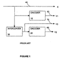
- FIG. 1 depicts a standard turbo encoder. It consists of two encoders 10 and 20 and an interleaver 30. The encoders 10 and 20 are arranged in a parallel concatenation with the interleaver 30 before the second encoder 20. The output of the first encoder 10 is a low-weight code 50 and the output of the second encoder 20 is a high-weight code 60.
- outputs may go to a device such as a code puncturing mechanism (not shown) to periodically delete selected bits to reduce coding overhead.
- a device such as a code puncturing mechanism (not shown) to periodically delete selected bits to reduce coding overhead.
- the output of the interleaver 70 may also be transmitted directly to the puncturing mechanism, but it is not necessary.
- the present invention may also be used with other non turbo code systems that require code interleaving.
- the present invention discloses two embodiments of an interleaver which can improve the performance of conventional turbo codes.
- the first embodiment will be referred to as a Galya interleaver and the second embodiment will be referred to as a frequency hopping (FH) interleaver.
- FH frequency hopping
- Both of these embodiments are based on number theory and both of these embodiments may be realized in software or hardware (i.e. application specific integrated circuits (ASIC), programmable logic arrays (PLA), or any other suitable logic devices, the construction of which is well knows).
- ASIC application specific integrated circuits
- PDA programmable logic arrays
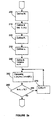
- FIGS. 2a and 2bh show the implementation of the above embodiment in either software or hardware.
- the above equations may be performed in a parallel or serial manner.
- step 200 defines a parameter representing block length N 1 .
- An array i 1 (n 1 ) for storing the bit sequence is defined (step 210) to size N 1 and initialized.
- a prime member P 1 is defined (step 220) which is greater than N 1 .
- Step 230 defines the initial root of N 1 called ⁇ 1 .
- a counter n1 is defined and initialized to one (step 240) and incremented (step 270) for each pass of the loop.
- the counter determines when to break out of a loop which calculates (step 250) the bit sequence, i 1 (n 1 ), for each symbol in the data frame.
- the loop is conditioned to break when the entire data frame has been permuted.
- the loop can also be adjusted to interleave a portion of the received or transmitted data frames.
- step 400 defines a parameter representing block length N 2 .
- An array for storing the bit sequence is defined (step 410) to size N 2 and initialized.
- a prime number P 2 is defined (step 420) which is greater than N 2 .
- Step 430 defines the initial root of N 2 called ⁇ 2 .
- a counter n 2 is defined and initialized to one (step 440) and incremented (step 470) for each pass of the loop.
- the counter determines when to break out of a loop which calculates (step 450) the bit sequence, i 2 (n 2 ), for each symbol in the data frame.
- the loop is conditioned to break when the entire data frame has been permuted.
- the loop can also be adjusted to interleave a portion of the received or transmitted data frames.
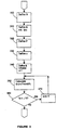
- FIG. 3 is an implementation of the above embodiment in either software or hardware.
- Step 300 defines a parameter representing block length N.
- An array for storing the bit sequence is defined (step 310) to size N and initialized.
- a prime number P is defined (step 320) which is greater than N.
- Step 330 defines the initial root of N called ⁇ .
- a counter n is defined and initialized to one (step 340) and incremented (step 370) for each pass of the loop.
- the counter determines when to break out of a loop which calculates (step 350) the bit sequence, i(n), for each symbol in the data frame.
- the loop is conditioned to break when the entire data frame has been permuted.
- the loop can be adjusted to interleave a portion of the received or transmitted data frames.
- any initialization value for the array i(n), i 1 (n 1 ), i 2 (n 2 ) can be used and still be within the scope of the invention.
- the initialization data can consist of zeros, ones, twos, etc., or a template may be created with different starting values.
- n, n 1 , and n 2 can be any integer and the loop break conditions n ⁇ N,n 1 ⁇ N 1 , and n 2 ⁇ N 2 can be adjusted accordingly and still be within the scope of this invention.
- the disclosed interleavers are compatible with existing turbo codes structure and are compatible with the current decoding algorithm. These interleavers offer superior performance without increasing system complexity.
- de-interleavers can be used to decode the interleaved data frames.
- de-interleavers used in decoding turbo codes is also well known in the art. As such they are not further discussed herein.
- the invention efficiently attains the objects set forth above, among those made apparent from the preceding description.
- the invention provides systems and methods of interleaving codes.
Landscapes
- Physics & Mathematics (AREA)
- Probability & Statistics with Applications (AREA)
- Engineering & Computer Science (AREA)
- Theoretical Computer Science (AREA)
- Error Detection And Correction (AREA)
- Detection And Prevention Of Errors In Transmission (AREA)
- Detection And Correction Of Errors (AREA)
Description
- This invention relates to the field of electronic communications systems and, more particularly, to interleavers for performing code modulation.
- Techniques for encoding communication channels, known as coded modulation, have been found to improve the bit error rate (BER) of electronic communication systems such as modem and wireless communication systems. One example of transmitting coded information, is shown in EP 0 235 477 A1 which reveals a method and apparatus for the transmission of coded information resistant to mixing such that Bn symbols and B words coded with n symbols are interlaced according to an order given by the following law: xk=xo + kp modulo B.n, xo being the starting point in the sequence Bn symbols and p being a first number with Bn, k taking a value between 0 and Bn-1. Successive sequences of B.n symbols can be linked in different orders generated by the same law but with different starting points x0 and different steps p.
- Turbo coded modulation has proven to be a practical, power-efficient, and bandwidth-efficient modulation method for "random-error" channels characterized by additive white Gaussian noise (AWGN) or fading. These random-error channels can be found, for example, in the code division multiple access (CDMA) environment.
- The key innovation of turbo codes is an interleaver which permutes the original received or transmitted data frame before input to a second encoder. Performing is accomplished by a processor performing a randomizing algorithm, the construction of which is well known. Combining the permuted data frames with the original data frames has shown to achieve low bit-error rates in AWGN and fading channels. The interleaving process increases the diversity in the data in such a way that if the modulated symbol is distorted in transmission the error may be recoverable with the use of error correcting algorithms in the decoder.
- A conventional interleaver collects, or frames, the signal points to be transmitted into a matrix, where the matrix is sequentially filled up a row at a time. After a predefined number of signal points have been framed, the interleaver is emptied by sequentially reading out the columns of the matrix for transmission. As a result, signal points in the same row of the matrix that were near each other in the original signal point flow are separated by a number of signal points equal to the number of rows in the matrix. Ideally, the number of columns and rows would be pricked such that interdependent signal points, after transmission, would be separated by more than the expected length of an error burst for the channel. However, this may not be practicable. As the number of rows is increased, so is the signal delay due to the framing of the signal points. As a result, there is a system constraint on the size of the interleaver in order to keep the signal delay within acceptable limits. On the other hand, constraining the size of the interleaver limits the separation of the time-diverse interdependent signal points and thus limits the improvement in error performance achieved by the interleaver.
- There are two conventional interleaving methods; uniform interleaving (i.e. a regular interleaving pattern); and non-uniform interleaving (i.e. a pseudo-irregular interleaving pattern). In the case of uniform interleaving, finite code words (FC) of higher weight can be constructed from FCs of lower weight. Therefore a certain "repetitive pattern" of low-weight FC output sequences can occur in the output stream of a uniform-interleaving turbo coder. However, uniform interleaving does not sufficiently de-correlate the output of the two encoders, hence the minimum distance of the resulting turbo code does not increase as one might expect.
- On the other hand, non-uniform interleaving achieves better "maximum scattering" of data and "maximum disorder" of the output sequence, which means that the redundancy introduced by the two convolutional codes is more equally spread in the output sequence of the turbo encoder. The minimum distance is increased to much higher values than for uniform interleaving. A persistent problem for non-uniform interleaving is how to achieve sufficient "'non-uniformity", since the interleaving algorithms can only be based on pseudo-irregular patterns. Besides this, the effort for implementing the scheme should be reasonable for practical applications. Furthermore, conventional interleavers require a significant amount of memory in the encoder. Conventional interleaving matrices also require delay compensations, which limit their use for applications with real-time requirements.
- Accordingly, there exists a need for systems and methods of interleaving codes that require minimal delay compensations.
- It is thus an object of the present invention to provide systems and methods of interleaving codes that improve non-uniformity.
- It is also an object of the present invention to provide systems and methods of interleaving codes that require minimal delay compensations.
- In accordance with the teachings of the present invention, these and other objects may be accomplished by the present invention, which interleaves a data frame, where the data frame has a predetermined size and is made up of portions. An embodiment of the invention includes a memory configured to receive and store the data frame. Once received, the data frame is indexed by a plurality of rows having a predetermined row size and a plurality of columns having a predetermined column size. The product of the predetermined row size and the predetermined column size equals the predetermined size of the data frame.
- A processor is coupled to the memory and used for separating the data frame into a plurality of portions. The processor also is used for generating a permuted sequence of the plurality of portions which are indexed by the plurality of rows in accordance with i1(n1) =α1^(n1)mod(P1), where P1 is a prime number greater than the predetermined row size, where n1 is an integer in the range of 1 through and including P1-1, and where α1 is the root of P1. This algorithm enables i1(n1) to be a unique number between 1 and the predetermined row size.
- The generation of a congruential sequence of the form i1(n1)=α1^(n1)mod(P1) is described in George E Andrews "Number Theory", Dover Publications Inc. New York 1971 and D:Kunth "The Art of Programming Vol. II" Addison Wesley, 1998. However, these sequences have not been used for permuting frame portions in order to interleave dataframes.
- The processor is also configured to generate a permuted sequence of the plurality of portions indexed by the plurality of columns in accordance with i2(n2)=α2^(n2)mod(P2), where P2 is a prime number greater than the predetermined column size, where n2 is an integer in the range of 1 through and including P2-1, and where α2 is a root of P2. Ths algorithm enables i2(n2) to be a unique number between 1 and the predetermined column size. The result is interleaved portions of the dataframe.
- The invention will be more clearly understood by reference to the following detailed description of an exemplary embodiment in conjunction with the accompanying drawings, in which:
- FIG. 1 is a diagram of a typical turbo encoder.
- FIGS. 2a and 2b are flowchart diagrams illustrating the operation of the improved interleaver for turbo codes in accordance with the present invention.
- FIG. 3 is a flow chart diagram illustrating another embodiment of the improved interleaver for turbo codes in accordance with the present invention.
-
- The present invention is an apparatus and method for interleaving codes. The interleaver takes each incoming data frame of N data bits and rearranges them in a pseudorandom fashion prior to encoding by a second encoder. This invention can be used in satellite communication systems, wireless telephone systems, modems, computers, and the like.
- The interleaver sorts the bits in a manner that lacks that any apparent order. The present invention will perform better than conventional interleavers even if the data frame is small (i.e., N on the order of a few thousand). Ths is accomplished by obtaining more diverse "scattering" than conventional interleavers. FIG. 1 depicts a standard turbo encoder. It consists of two encoders 10 and 20 and an interleaver 30. The encoders 10 and 20 are arranged in a parallel concatenation with the interleaver 30 before the second encoder 20. The output of the first encoder 10 is a low-weight code 50 and the output of the second encoder 20 is a high-weight code 60. These outputs may go to a device such as a code puncturing mechanism (not shown) to periodically delete selected bits to reduce coding overhead. In addition, the output of the interleaver 70 may also be transmitted directly to the puncturing mechanism, but it is not necessary. In addition the present invention may also be used with other non turbo code systems that require code interleaving.
- The present invention discloses two embodiments of an interleaver which can improve the performance of conventional turbo codes. The first embodiment will be referred to as a Galya interleaver and the second embodiment will be referred to as a frequency hopping (FH) interleaver. Both of these embodiments are based on number theory and both of these embodiments may be realized in software or hardware (i.e. application specific integrated circuits (ASIC), programmable logic arrays (PLA), or any other suitable logic devices, the construction of which is well knows).
- In the first embodiment, the Galya interleaver, the information bit matrix has N1 rows and N2 columns such that N1*N2 =N. Further, there exist prime number P1 and P2 which are respectively greater thanN1 and N2 (i.e. P1>N1 and P2>N2). It is preferred that these prime numbers should be the lowest prime numbers greater than N1 and N2, respectively, but it is not required. Initial roots α1 and α2 may be determined for these prime numbers using conventional methods. Employing the above noted parameters, the bit sequence generation for the Galya interleaver is defined by the following equations:
- For N-256, we have N1=N2=16, P1=P2=17, α1=α1=3.
- FIGS. 2a and 2bh show the implementation of the above embodiment in either software or hardware. The above equations may be performed in a parallel or serial manner. In FIG. 2a, step 200 defines a parameter representing block length N1. An array i1(n1) for storing the bit sequence is defined (step 210) to size N1 and initialized. Next, a prime member P1 is defined (step 220) which is greater than N1. Step 230 defines the initial root of N1 called α1. A counter n1 is defined and initialized to one (step 240) and incremented (step 270) for each pass of the loop. As step 260 shows, the counter determines when to break out of a loop which calculates (step 250) the bit sequence, i1(n1), for each symbol in the data frame. The loop is conditioned to break when the entire data frame has been permuted. The loop can also be adjusted to interleave a portion of the received or transmitted data frames.
- In FIG. 2b, step 400 defines a parameter representing block length N2. An array for storing the bit sequence is defined (step 410) to size N2 and initialized. Next, a prime number P2 is defined (step 420) which is greater than N2. Step 430 defines the initial root of N2 called α2. A counter n2 is defined and initialized to one (step 440) and incremented (step 470) for each pass of the loop. As step 460 shows, the counter determines when to break out of a loop which calculates (step 450) the bit sequence, i2(n2), for each symbol in the data frame. The loop is conditioned to break when the entire data frame has been permuted. The loop can also be adjusted to interleave a portion of the received or transmitted data frames.
- In the second embodiment, the FH interleaver, assume that the block length (or data frame size) is length N. Further, there exists a prime number P which is greater than N. It is preferred that the prime number should be the lowest prime number greater than N, but it is not required, For a given prime number it is possible to find an initial root α using conventional methods. Thus, for example, if N=256, then P=257 and α=3. Employing the above noted parameters, the bit sequence generation for the FH interleaver is defined by the following equation:
- FIG. 3 is an implementation of the above embodiment in either software or hardware. Step 300 defines a parameter representing block length N. An array for storing the bit sequence is defined (step 310) to size N and initialized. Next, a prime number P is defined (step 320) which is greater than N. Step 330 defines the initial root of N called α. A counter n is defined and initialized to one (step 340) and incremented (step 370) for each pass of the loop. As step 360 shows, the counter determines when to break out of a loop which calculates (step 350) the bit sequence, i(n), for each symbol in the data frame. The loop is conditioned to break when the entire data frame has been permuted. The loop can be adjusted to interleave a portion of the received or transmitted data frames.
- Those skilled in the art will realize that any initialization value for the array i(n), i1(n1), i2(n2) can be used and still be within the scope of the invention. For example the initialization data can consist of zeros, ones, twos, etc., or a template may be created with different starting values. Thus, n, n1, and n2 can be any integer and the loop break conditions n≤N,n1≤N1, and n2≤N2 can be adjusted accordingly and still be within the scope of this invention.
- The disclosed interleavers are compatible with existing turbo codes structure and are compatible with the current decoding algorithm. These interleavers offer superior performance without increasing system complexity.
- In addition, those skilled in the art will realize that de-interleavers can be used to decode the interleaved data frames. The construction of de-interleavers used in decoding turbo codes is also well known in the art. As such they are not further discussed herein. Accordingly, a de-interleaver corresponding to the first embodiment can be constructed using the permuted sequences:
- It will thus be seen that the invention efficiently attains the objects set forth above, among those made apparent from the preceding description. In particular, the invention provides systems and methods of interleaving codes.
- It will be understood that changes may be made in the above construction and in the foregoing sequences of operation without departing from the scope of the invention. It is accordingly intended that all matter contained in the above description or shown in the accompanying drawings be interpreted al illustrative rather than in a limiting sense.
- It is also to be understood that the following claims are intended to cover all of the generic and specific features of the invention as described herein. Having described the invention, what is claimed as new and secured by Letters Patent is:
Claims (34)
- An apparatus for interleaving a plurality of portions of a data frame having a predetermined size characterised by:means for receiving and storing said data frame;means for separating said data frame into said plurality portions; andmeans for permuting said plurality of portions in accordance with i(n)=αnmod(P), wherein P is a prime number greater than said predetermined size of said data frame, wherein n is an integer in the range of 1 through and including P-1, and wherein α is a root of P, the algorithm enabling i(n) to be a unique number between 1 and said predetermined size.
- The apparatus according to claim 1, characterised in that said plurality of portions have a predetermined size, wherein said predetermined size is at least one bit.
- The apparatus according to claim 1, characterised in that said means for permuting is accomplished using an application specific integrated circuit (ASIC).
- The apparatus according to claim 1, characterised in that said means for permuting is accomplished using a microprocessor.
- The apparatus according to claim 1, characterised in that wherein said permuting is accomplished using software.
- The apparatus according to claim 1, further characterised by means for deinterleaving said plurality of portions in accordance with a permuted sequence.
- The apparatus according to claim 1, characterised in that:said means for receiving and storing said data frame includes a memory configured to receive and store said data frame indexed by a plurality of rows having a predetermined row size and plurality of columns having a predetermined column size, wherein the product of said predetermined row size and said predetermined column size equals said predetemied size of said data frame;said means for separating said data frame includes a processor coupled to said memory for separating said plurality of portions and for generating a permuted sequence of said plurality of portions indexed by said plurality of rows in accordance with i1(n1)=α1^(n1)mod(P1), where P1 is a prime number greater than the predetermined row size, where n1 is an integer in the range of 1 through and including P1-1, and where α1 is a root of P1 which enables i1(n1)to be unique number between 1 and said predetermined row size; and
said processor being configured to generate a permuted sequence of said plurality of portions indexed by said plurality of columns in accordance with i2(n2)= α2^(n2)mod(P2), wherein P2 is a prime number greater than said predetermined column size, wherein n2 is an integer in the range of 1 through and including P2-1, and wherein α2 is a root of P2 which enables i2(n2)to be a unique number between 1 and said predetermined column size, whereby portions of said data frame are interleaved. - The apparatus according to claim 7, characterised in that said plurality of portions have a predetermined size, wherein said predetermined size is at least one bit.
- The apparatus according to claim 7, characterised in that said processor is an application specific integrated circuit (ASIC).
- The apparatus according to claim 7, further characterised by said de-interleaver, wherein said de-interleaver deinterleaves said plurality of portions indexed by said plurality of rows in accordance with said permuted sequence i1(n1)=α1^(n1)mod(P1).
- The apparatus according to claim 7, further characterised by a de-interleaver, wherein said de-interleaver deinterleaves said plurality of portions indexed by said plurality of columns in accordance with said permuted sequence i2(n2)=α2^(n2)mod(P2).
- The apparatus according to claim 1, characterised in that said means for receiving and storing said data frame includes a memory configured to receive and store said data frame; and
said means for separating said data frame includes a processor coupled to said memory for separating said data frame into said plurality of portions and for generating a permuted sequence of said plurality of portions in accordance with i(n)=αR mod(P), wherein P is a prime number greater than said predetermined size of said data frame, wherein n is an integer in the range of 1 through and including P-1, and where α is a root of P which enable i(n) to be a unique number between 1 and said predetermined size of said data frame, whereby portions of said data frame are interleaved. - The apparatus according to claim 12, characterised in that said plurality of portions have a predetermined size, wherein said predetermined size is at least one bit.
- The apparatus according to claim 12, characterised in that said processor is an application specific integrated circuit (ASIC).
- The apparatus according to claim 12, further characterised by a de-interleaver, wherein said de-interleaver deinterleaves said plurality of portions in accordance with said permuted sequence.
- The apparatus according to claim 1, further characterised by:means for indexing said data frame by a plurality of rows having a predetermined row size and a plurality of columns having a predetermined column size, wherein the product of said predetermined row size and said predetermined column size equals said predetermined size and said data frame;means for permuting said plurality of portions indexed by said plurality of rows in accordance with i1(n1)=α1^(n1)mod(P1), wherein P1 is a prime number greater than said predetermined low size, wherein n1 is an integer in the range of 1 through and including P1-1, and wherein α1 is a root of P1 which enables i1(n1) to be a unique number between 1 and said predetermined row size; andmeans for permuting said plurality of portions indexed by said plurality of columns in accordance with i2(n2)=α2^(n2)mod(P2), wherein P2 is a prime number greater than said predetermined column size, wherein n2 is an integer in the range of 1 through and including P2-1, and wherein α2 is a root of P2 which enables i2(n2) to be a unique number between 1 and said predetermined column size.
- The apparatus according to claim 16, characterised in that said plurality of portions have a predetermined size, wherein said predetermined size is at least one bit.
- The apparatus according to claim 16, characterised in that said means for permuting is accomplished by using an application specific integrated circuit (ASIC).
- The apparatus according to claim 16, characterised in that said means for permuting is accomplished by using a microprocessor.
- The apparatus according to claim 16, characterised in that said means for another permuting is accomplished by using software.
- The apparatus according to claim 16, further characterised by de-interleaver means for deinterleaving said plurality of portions indexed by said plurality of rows in accordance with said another permuted sequence i1(n1)=α1^(n1)mod(P1).
- The apparatus according to claim 16, further characterised by de-interleaver means for deinterleaving said plurality of portions indexed by said plurality of columns in accordance with said permuted sequence i2(n2)=α2^(n2)mod(P2).
- A method for interleaving a plurality of portions of a data frame having a predetermined size characterised by:receiving and storing said data frame;separating said data frame into said plurality portion; andpermuting said plurality of portions in accordance with i(n)=αnmod(P), wherein P is a prime number greater than said predetermined size of said data frame, wherein n is an integer in the range of 1 through and including P-1, and wherein α is a root of P, the algorithm enabling i(n) to be a unique number between 1 and said predetermined size of said data frame.
- The method according to claim 23, characterised in that said plurality of portions have predetermined size, wherein said predetermined size is at least one bit
- The method according to claim 23, characterised in that said permuting is accomplished by using an application specific integrated circuit (ASIC).
- The method according to claim 23, characterised in that said permuting is accomplished by using a microprocessor.
- The method according to claim 23, characterised in that said permuting is accomplished by using software.
- The method according to claim 23, further characterised by:indexing said data frame by a plurality of rows having a predetermined row size and a plurality of columns having a predetermined column size, wherein the product of said predetermined row size and said predetermined column size equals said predetermined size of data frame;permuting said plurality of portions indexed by said plurality of rows in accordance with i1(n1)= α1^(n1)mod(P1), wherein P1 is a prime number greater than said predetermined row size, wherein n1 is an integer in the range of 1 through and including P1-1, and wherein α1 is a root of P1 which enables i1(n1) to be a unique number between 1 and said predetermined row size; andpermuting said plurality of portions indexed by said plurality of columns in accordance with i2(n2)=α2^(n2)mod(P2), wherein P2 is a prime number greater than said predetermined column size, wherein n2 is an integer in the range of 1 through and including P2-1, and wherein α2 is a root of P2 which enables i2(n2) to be a unique number between 1 and said predetermined column size, whereby portions of said data frame are interleaved.
- The method according to claim 28, characterised in that said plurality of portions have a predetermined size, wherein said predetermine size is at least one bit.
- The method according to claim 28, characterised in that said permuting is accomplished by using an application specific integrated circuit (ASIC).
- The method according to claim 28, characterised in that said permuting is accomplished by using a microprocessor.
- The method according to claim 28, characterised in that said permuting is accomplished by using software.
- The method according to claim 28, further characterised by deinterleaving said plurality of portions indexed by said plurality of rows in accordance with said permuted sequence i1(n1)= α1^(n1)mod(P1).
- The method according to claim 28, further characterised by deinterleaving said plurality of portions indexed by said plurality of columns in accordance with said permuted sequence i2(n2)= α2^(n2)mod(P2).
Applications Claiming Priority (5)
| Application Number | Priority Date | Filing Date | Title |
|---|---|---|---|
| US9508598P | 1998-08-03 | 1998-08-03 | |
| US95085P | 1998-08-03 | ||
| US196461 | 1998-11-19 | ||
| US09/196,461 US6347385B1 (en) | 1998-08-03 | 1998-11-19 | Interleavers for turbo code |
| PCT/IB1999/001369 WO2000008770A1 (en) | 1998-08-03 | 1999-08-02 | Improved interleavers for turbo code |
Publications (2)
| Publication Number | Publication Date |
|---|---|
| EP1103102A1 EP1103102A1 (en) | 2001-05-30 |
| EP1103102B1 true EP1103102B1 (en) | 2003-02-05 |
Family
ID=26789705
Family Applications (1)
| Application Number | Title | Priority Date | Filing Date |
|---|---|---|---|
| EP99931422A Expired - Lifetime EP1103102B1 (en) | 1998-08-03 | 1999-08-02 | Improved interleavers for turbo code |
Country Status (10)
| Country | Link |
|---|---|
| US (1) | US6347385B1 (en) |
| EP (1) | EP1103102B1 (en) |
| JP (1) | JP4309586B2 (en) |
| CN (1) | CN1140060C (en) |
| BR (1) | BR9912670B1 (en) |
| CA (1) | CA2337916C (en) |
| DE (1) | DE69905255T2 (en) |
| HK (1) | HK1038448A1 (en) |
| MX (1) | MXPA01000897A (en) |
| WO (1) | WO2000008770A1 (en) |
Families Citing this family (23)
| Publication number | Priority date | Publication date | Assignee | Title |
|---|---|---|---|---|
| US7536624B2 (en) * | 2002-01-03 | 2009-05-19 | The Directv Group, Inc. | Sets of rate-compatible universal turbo codes nearly optimized over various rates and interleaver sizes |
| US6430722B1 (en) * | 1998-01-23 | 2002-08-06 | Hughes Electronics Corporation | Forward error correction scheme for data channels using universal turbo codes |
| EP1046236B1 (en) * | 1998-08-17 | 2016-02-24 | Dtvg Licensing, Inc | Turbo code interleaver with near optimal performance |
| KR100333469B1 (en) | 1998-08-27 | 2002-04-25 | 마이클 더블유.세일즈 | Method for a general turbo code trellis termination |
| CA2298919C (en) | 1999-02-19 | 2006-04-18 | Ntt Mobile Communications Network Inc. | Interleaving and turbo encoding using prime number permutations |
| US6543013B1 (en) * | 1999-04-14 | 2003-04-01 | Nortel Networks Limited | Intra-row permutation for turbo code |
| FI106758B (en) * | 1999-04-16 | 2001-03-30 | Nokia Networks Oy | Segmentation mechanism for block encoder |
| IL141800A0 (en) * | 1999-07-06 | 2002-03-10 | Samsung Electronics Co Ltd | Rate matching device and method for a data communication system |
| CA2550761C (en) * | 1999-07-08 | 2009-05-26 | Nortel Networks Limited | Puncturing of convolutional codes |
| US6625763B1 (en) * | 2000-07-05 | 2003-09-23 | 3G.Com, Inc. | Block interleaver and de-interleaver with buffer to reduce power consumption |
| KR100361033B1 (en) * | 2001-01-16 | 2003-01-24 | 한국과학기술원 | Multicarrier DS/CDMA system using a turbo code with nonuniform repetition coding |
| US7068701B2 (en) * | 2001-04-16 | 2006-06-27 | Motorola, Inc. | Data transmission and reception within a spread-spectrum communication system |
| JP3624874B2 (en) * | 2001-11-19 | 2005-03-02 | 日本電気株式会社 | Interleaving sequence generator, interleaver, turbo encoder, and turbo decoder |
| US7091889B2 (en) | 2002-09-09 | 2006-08-15 | Telefonaktiebolaget Lm Ericsson (Publ) | Speed and memory optimized interleaving |
| US7068703B2 (en) * | 2003-02-18 | 2006-06-27 | Qualcomm, Incorporated | Frequency hop sequences for multi-band communication systems |
| US7600164B2 (en) * | 2004-12-17 | 2009-10-06 | Telefonaktiebolaget Lm Ericsson (Publ) | Interleaving/de-interleaving using compressed bit-mapping sequences |
| US8082479B2 (en) * | 2006-02-02 | 2011-12-20 | Qualcomm Incorporated | Methods and apparatus for generating permutations |
| US7925956B2 (en) * | 2006-10-03 | 2011-04-12 | Motorola Mobility, Inc. | Method and apparatus for encoding and decoding data |
| US8356232B2 (en) * | 2006-10-06 | 2013-01-15 | Motorola Mobility Llc | Method and apparatus for encoding and decoding data |
| US7949926B2 (en) * | 2006-11-30 | 2011-05-24 | Motorola Mobility, Inc. | Method and apparatus for encoding and decoding data |
| US7853858B2 (en) * | 2006-12-28 | 2010-12-14 | Intel Corporation | Efficient CTC encoders and methods |
| US8693570B2 (en) * | 2008-10-31 | 2014-04-08 | Industrial Technology Research Institute | Communication methods and systems having data permutation |
| WO2018187902A1 (en) | 2017-04-10 | 2018-10-18 | Qualcomm Incorporated | An efficient interleaver design for polar codes |
Family Cites Families (12)
| Publication number | Priority date | Publication date | Assignee | Title |
|---|---|---|---|---|
| US4394642A (en) | 1981-09-21 | 1983-07-19 | Sperry Corporation | Apparatus for interleaving and de-interleaving data |
| JPH0697542B2 (en) * | 1985-05-14 | 1994-11-30 | 松下電器産業株式会社 | Interleave circuit |
| FR2592258B1 (en) | 1985-12-23 | 1991-05-03 | Thomson Csf | METHOD AND DEVICE FOR RADIOELECTRIC TRANSMISSION OF ENCODED INFORMATION, RESISTANT TO INTERFERENCE |
| JPS6437125A (en) | 1987-07-31 | 1989-02-07 | Csk Corp | Cross coding method and device therefor |
| FR2675971B1 (en) | 1991-04-23 | 1993-08-06 | France Telecom | CORRECTIVE ERROR CODING METHOD WITH AT LEAST TWO SYSTEMIC CONVOLUTIVE CODES IN PARALLEL, ITERATIVE DECODING METHOD, CORRESPONDING DECODING MODULE AND DECODER. |
| FR2706054B1 (en) | 1993-06-02 | 1995-07-13 | Alcatel Mobile Comm France | Method for interleaving a sequence of data elements, and corresponding interleaving device. |
| US5483541A (en) | 1993-09-13 | 1996-01-09 | Trw Inc. | Permuted interleaver |
| FR2737363B1 (en) | 1995-07-27 | 1997-09-05 | France Telecom | INTERLEAVING / DE-INTERLACING DATA ELEMENTS |
| US5764649A (en) * | 1996-03-29 | 1998-06-09 | Amati Communications Corporation | Efficient address generation for convolutional interleaving using a minimal amount of memory |
| KR100192797B1 (en) * | 1996-07-01 | 1999-06-15 | 전주범 | An architecture of convolutional interleaver using sram |
| US5754565A (en) | 1996-10-15 | 1998-05-19 | Quantum Corporation | Reconstruction of syndromes for bi-level on-the-fly error correction in disk drive systems |
| ATE292336T1 (en) * | 1997-01-31 | 2005-04-15 | Cit Alcatel | METHOD AND DEVICES FOR NESTING/DENESTHING DIGITAL DATA AND COMMUNICATIONS SYSTEM |
-
1998
- 1998-11-19 US US09/196,461 patent/US6347385B1/en not_active Expired - Lifetime
-
1999
- 1999-08-02 WO PCT/IB1999/001369 patent/WO2000008770A1/en active IP Right Grant
- 1999-08-02 JP JP2000564307A patent/JP4309586B2/en not_active Expired - Lifetime
- 1999-08-02 BR BRPI9912670-2A patent/BR9912670B1/en not_active IP Right Cessation
- 1999-08-02 DE DE69905255T patent/DE69905255T2/en not_active Expired - Lifetime
- 1999-08-02 EP EP99931422A patent/EP1103102B1/en not_active Expired - Lifetime
- 1999-08-02 CA CA002337916A patent/CA2337916C/en not_active Expired - Lifetime
- 1999-08-02 MX MXPA01000897A patent/MXPA01000897A/en active IP Right Grant
- 1999-08-02 CN CNB998093084A patent/CN1140060C/en not_active Expired - Lifetime
-
2001
- 2001-12-31 HK HK01109223A patent/HK1038448A1/en not_active IP Right Cessation
Also Published As
| Publication number | Publication date |
|---|---|
| US6347385B1 (en) | 2002-02-12 |
| DE69905255D1 (en) | 2003-03-13 |
| BR9912670B1 (en) | 2012-09-04 |
| WO2000008770A1 (en) | 2000-02-17 |
| CA2337916A1 (en) | 2000-02-17 |
| DE69905255T2 (en) | 2003-09-11 |
| BR9912670A (en) | 2001-05-02 |
| HK1038448A1 (en) | 2002-03-15 |
| EP1103102A1 (en) | 2001-05-30 |
| CN1140060C (en) | 2004-02-25 |
| JP4309586B2 (en) | 2009-08-05 |
| MXPA01000897A (en) | 2004-07-30 |
| CN1311922A (en) | 2001-09-05 |
| JP2002522945A (en) | 2002-07-23 |
| CA2337916C (en) | 2006-05-09 |
Similar Documents
| Publication | Publication Date | Title |
|---|---|---|
| EP1103102B1 (en) | Improved interleavers for turbo code | |
| EP1046236B1 (en) | Turbo code interleaver with near optimal performance | |
| EP2262144B1 (en) | Apparatus and method for generating codes in communication system | |
| EP1601109B1 (en) | Adaptive channel encoding method and device | |
| US6289486B1 (en) | Adaptive channel encoding method and device | |
| US7069492B2 (en) | Method of interleaving a binary sequence | |
| US6785859B2 (en) | Interleaver for variable block size | |
| KR20020067382A (en) | Code generating and decoding apparatus and method in communication system | |
| EP1169777B1 (en) | Intra-row permutation for turbocode | |
| US6625762B1 (en) | Interleaving device and method for turbocoding and turbodecoding | |
| US20010034868A1 (en) | Interleaver design for parsed parallel concatenated codes | |
| EP1145444B1 (en) | Block interleaving for turbo coding | |
| EP1303051B1 (en) | Interference decorrelation of multiple strem interpolated data | |
| KR100530400B1 (en) | Interleaver pattern modification | |
| US7873897B2 (en) | Devices and methods for bit-level coding and decoding of turbo codes | |
| US7886203B2 (en) | Method and apparatus for bit interleaving and deinterleaving in wireless communication systems | |
| US7248620B2 (en) | System for treatment data by the frequency hopping method | |
| EP1926215B1 (en) | Parallel concatenated zigzag codes with UMTS turbo interleavers | |
| KR100454952B1 (en) | Adaptive Channel Coding Method and Apparatus | |
| Raje et al. | Review paper on study of various Interleavers and their significance | |
| US20050289431A1 (en) | Efficient address generation for Forney's modular periodic interleavers | |
| GB2332836A (en) | Adaptive convolutional interleaver and deinterleaver | |
| KR20040037624A (en) | Method and apparatus for deinterleaving an interleaved data stream in communication system |
Legal Events
| Date | Code | Title | Description |
|---|---|---|---|
| PUAI | Public reference made under article 153(3) epc to a published international application that has entered the european phase |
Free format text: ORIGINAL CODE: 0009012 |
|
| 17P | Request for examination filed |
Effective date: 20010306 |
|
| AK | Designated contracting states |
Kind code of ref document: A1 Designated state(s): DE FR GB |
|
| 17Q | First examination report despatched |
Effective date: 20010620 |
|
| GRAG | Despatch of communication of intention to grant |
Free format text: ORIGINAL CODE: EPIDOS AGRA |
|
| GRAG | Despatch of communication of intention to grant |
Free format text: ORIGINAL CODE: EPIDOS AGRA |
|
| GRAH | Despatch of communication of intention to grant a patent |
Free format text: ORIGINAL CODE: EPIDOS IGRA |
|
| GRAH | Despatch of communication of intention to grant a patent |
Free format text: ORIGINAL CODE: EPIDOS IGRA |
|
| GRAA | (expected) grant |
Free format text: ORIGINAL CODE: 0009210 |
|
| AK | Designated contracting states |
Designated state(s): DE FR GB |
|
| REG | Reference to a national code |
Ref country code: GB Ref legal event code: FG4D |
|
| REF | Corresponds to: |
Ref document number: 69905255 Country of ref document: DE Date of ref document: 20030313 Kind code of ref document: P |
|
| ET | Fr: translation filed | ||
| RAP2 | Party data changed (patent owner data changed or rights of a patent transferred) |
Owner name: NORTEL NETWORKS LIMITED |
|
| PLBE | No opposition filed within time limit |
Free format text: ORIGINAL CODE: 0009261 |
|
| STAA | Information on the status of an ep patent application or granted ep patent |
Free format text: STATUS: NO OPPOSITION FILED WITHIN TIME LIMIT |
|
| 26N | No opposition filed |
Effective date: 20031106 |
|
| REG | Reference to a national code |
Ref country code: FR Ref legal event code: TP Owner name: ROCKSTAR BIDCO, LP, US Effective date: 20121206 |
|
| REG | Reference to a national code |
Ref country code: DE Ref legal event code: R082 Ref document number: 69905255 Country of ref document: DE Representative=s name: HERNANDEZ, YORCK, DIPL.-ING., DE Effective date: 20121206 Ref country code: DE Ref legal event code: R082 Ref document number: 69905255 Country of ref document: DE Representative=s name: WITTMANN HERNANDEZ PATENTANWAELTE PARTNERSCHAF, DE Effective date: 20121206 Ref country code: DE Ref legal event code: R082 Ref document number: 69905255 Country of ref document: DE Representative=s name: WITTMANN HERNANDEZ PATENTANWAELTE, DE Effective date: 20121206 Ref country code: DE Ref legal event code: R081 Ref document number: 69905255 Country of ref document: DE Owner name: BLACKBERRY LIMITED, WATERLOO, CA Free format text: FORMER OWNER: NORTEL NETWORKS LTD., MONTREAL, QUEBEC, CA Effective date: 20121206 Ref country code: DE Ref legal event code: R081 Ref document number: 69905255 Country of ref document: DE Owner name: RESEARCH IN MOTION LIMITED, WATERLOO, CA Free format text: FORMER OWNER: NORTEL NETWORKS LTD., MONTREAL, QUEBEC, CA Effective date: 20121206 Ref country code: DE Ref legal event code: R081 Ref document number: 69905255 Country of ref document: DE Owner name: RESEARCH IN MOTION LIMITED, CA Free format text: FORMER OWNER: NORTEL NETWORKS LTD., MONTREAL, CA Effective date: 20121206 |
|
| REG | Reference to a national code |
Ref country code: FR Ref legal event code: TP Owner name: RESEARCH IN MOTION LIMITED, CA Effective date: 20130226 |
|
| REG | Reference to a national code |
Ref country code: DE Ref legal event code: R082 Ref document number: 69905255 Country of ref document: DE Representative=s name: WITTMANN HERNANDEZ PATENTANWAELTE PARTNERSCHAF, DE |
|
| REG | Reference to a national code |
Ref country code: DE Ref legal event code: R082 Ref document number: 69905255 Country of ref document: DE Representative=s name: HERNANDEZ, YORCK, DIPL.-ING., DE Effective date: 20140925 Ref country code: DE Ref legal event code: R082 Ref document number: 69905255 Country of ref document: DE Representative=s name: WITTMANN HERNANDEZ PATENTANWAELTE PARTNERSCHAF, DE Effective date: 20140925 Ref country code: DE Ref legal event code: R081 Ref document number: 69905255 Country of ref document: DE Owner name: BLACKBERRY LIMITED, WATERLOO, CA Free format text: FORMER OWNER: RESEARCH IN MOTION LIMITED, WATERLOO, ONTARIO, CA Effective date: 20140925 |
|
| REG | Reference to a national code |
Ref country code: FR Ref legal event code: PLFP Year of fee payment: 17 |
|
| REG | Reference to a national code |
Ref country code: FR Ref legal event code: PLFP Year of fee payment: 18 |
|
| REG | Reference to a national code |
Ref country code: DE Ref legal event code: R082 Ref document number: 69905255 Country of ref document: DE Representative=s name: HERNANDEZ, YORCK, DIPL.-ING., DE |
|
| REG | Reference to a national code |
Ref country code: FR Ref legal event code: PLFP Year of fee payment: 19 |
|
| REG | Reference to a national code |
Ref country code: FR Ref legal event code: PLFP Year of fee payment: 20 |
|
| PGFP | Annual fee paid to national office [announced via postgrant information from national office to epo] |
Ref country code: DE Payment date: 20180829 Year of fee payment: 20 Ref country code: FR Payment date: 20180827 Year of fee payment: 20 |
|
| PGFP | Annual fee paid to national office [announced via postgrant information from national office to epo] |
Ref country code: GB Payment date: 20180828 Year of fee payment: 20 |
|
| REG | Reference to a national code |
Ref country code: DE Ref legal event code: R071 Ref document number: 69905255 Country of ref document: DE |
|
| REG | Reference to a national code |
Ref country code: GB Ref legal event code: PE20 Expiry date: 20190801 |
|
| PG25 | Lapsed in a contracting state [announced via postgrant information from national office to epo] |
Ref country code: GB Free format text: LAPSE BECAUSE OF EXPIRATION OF PROTECTION Effective date: 20190801 |