EP1100721B9 - Device for dispensing liquid from side by side arranged containers - Google Patents
Device for dispensing liquid from side by side arranged containers Download PDFInfo
- Publication number
- EP1100721B9 EP1100721B9 EP99937509A EP99937509A EP1100721B9 EP 1100721 B9 EP1100721 B9 EP 1100721B9 EP 99937509 A EP99937509 A EP 99937509A EP 99937509 A EP99937509 A EP 99937509A EP 1100721 B9 EP1100721 B9 EP 1100721B9
- Authority
- EP
- European Patent Office
- Prior art keywords
- reservoir
- containers
- liquid
- openings
- conduits
- Prior art date
- Legal status (The legal status is an assumption and is not a legal conclusion. Google has not performed a legal analysis and makes no representation as to the accuracy of the status listed.)
- Expired - Lifetime
Links
- 239000007788 liquid Substances 0.000 title claims abstract description 59
- XLYOFNOQVPJJNP-UHFFFAOYSA-N water Substances O XLYOFNOQVPJJNP-UHFFFAOYSA-N 0.000 claims description 76
- 230000005484 gravity Effects 0.000 claims description 3
- 235000012206 bottled water Nutrition 0.000 abstract description 7
- 239000000523 sample Substances 0.000 description 14
- 235000016213 coffee Nutrition 0.000 description 5
- 235000013353 coffee beverage Nutrition 0.000 description 5
- 235000013361 beverage Nutrition 0.000 description 4
- 210000003739 neck Anatomy 0.000 description 3
- 241001122767 Theaceae Species 0.000 description 2
- 238000013459 approach Methods 0.000 description 2
- 235000011389 fruit/vegetable juice Nutrition 0.000 description 2
- 235000013336 milk Nutrition 0.000 description 2
- 239000008267 milk Substances 0.000 description 2
- 210000004080 milk Anatomy 0.000 description 2
- 235000014214 soft drink Nutrition 0.000 description 2
- 235000013616 tea Nutrition 0.000 description 2
- 230000007423 decrease Effects 0.000 description 1
- 238000007599 discharging Methods 0.000 description 1
- 230000000694 effects Effects 0.000 description 1
- 238000010438 heat treatment Methods 0.000 description 1
- 238000012986 modification Methods 0.000 description 1
- 230000004048 modification Effects 0.000 description 1
- 230000037452 priming Effects 0.000 description 1
- 238000005086 pumping Methods 0.000 description 1
- 238000007789 sealing Methods 0.000 description 1
Images


Classifications
-
- B—PERFORMING OPERATIONS; TRANSPORTING
- B65—CONVEYING; PACKING; STORING; HANDLING THIN OR FILAMENTARY MATERIAL
- B65B—MACHINES, APPARATUS OR DEVICES FOR, OR METHODS OF, PACKAGING ARTICLES OR MATERIALS; UNPACKING
- B65B3/00—Packaging plastic material, semiliquids, liquids or mixed solids and liquids, in individual containers or receptacles, e.g. bags, sacks, boxes, cartons, cans, or jars
- B65B3/04—Methods of, or means for, filling the material into the containers or receptacles
-
- B—PERFORMING OPERATIONS; TRANSPORTING
- B67—OPENING, CLOSING OR CLEANING BOTTLES, JARS OR SIMILAR CONTAINERS; LIQUID HANDLING
- B67D—DISPENSING, DELIVERING OR TRANSFERRING LIQUIDS, NOT OTHERWISE PROVIDED FOR
- B67D1/00—Apparatus or devices for dispensing beverages on draught
- B67D1/0003—Apparatus or devices for dispensing beverages on draught the beverage being a single liquid
- B67D1/0009—Apparatus or devices for dispensing beverages on draught the beverage being a single liquid the beverage being stored in an intermediate container connected to a supply
-
- B—PERFORMING OPERATIONS; TRANSPORTING
- B65—CONVEYING; PACKING; STORING; HANDLING THIN OR FILAMENTARY MATERIAL
- B65B—MACHINES, APPARATUS OR DEVICES FOR, OR METHODS OF, PACKAGING ARTICLES OR MATERIALS; UNPACKING
- B65B39/00—Nozzles, funnels or guides for introducing articles or materials into containers or wrappers
- B65B2039/009—Multiple outlets
-
- B—PERFORMING OPERATIONS; TRANSPORTING
- B67—OPENING, CLOSING OR CLEANING BOTTLES, JARS OR SIMILAR CONTAINERS; LIQUID HANDLING
- B67D—DISPENSING, DELIVERING OR TRANSFERRING LIQUIDS, NOT OTHERWISE PROVIDED FOR
- B67D1/00—Apparatus or devices for dispensing beverages on draught
- B67D1/08—Details
- B67D1/0801—Details of beverage containers, e.g. casks, kegs
- B67D2001/0812—Bottles, cartridges or similar containers
- B67D2001/0818—Bottles, cartridges or similar containers arranged in series
Definitions
- the present invention generally relates to a liquid delivery system, and is more particularly directed to a water delivery system that automatically delivers water from a plurality of bottles to one or more outlets.
- Water dispensing units such as water coolers and the like, conventionally, dispense water from a single container, such as a five gallon bottle which sits atop of the water cooler. In an office or commercial environment, or in a home where a great deal of water is consumed, the bottle must be frequently changed to replenish the water supply.
- US 3927804 discloses apparatus for dispensing liquids from multiple bottles maintained in an inverted position.
- the bottles are held so that their contents are received into corresponding wells, which in turn are interconnected by a common channel structure.
- bottle neck extensions are used, which have the effect of increasing the height of the held bottles.
- US 3896972 discloses a remote liquor dispensing system including a rack for supporting bottles of liquor in an inverted position, and a series of flexible tubes connecting the bottles to a gravity feed manifold.
- US 4274557 discloses a beverage dispenser pumping system in which each bottle feeds into a corresponding container. The containers then share a common pumped output. However, no intercommunication of beverages among the bottles is possible.
- the present invention overcomes the described drawbacks and provides a new and unique system, as defined in the appended claims, which has the capacity to provide comparatively substantial quantities of liquids (e.g., water) by using a plurality of relatively large containers, which has the capability of providing liquid to one or more outlets, which can be maintained at different locations near or remote from the one or more liquid outlets, which can be replenished easily and on a less frequent basis, and which can operate automatically and continuously.
- the system includes a dispenser for holding a plurality of containers (e.g., five gallon bottles of water) at a desired location relative to the one or more outlets, and a unit for automatically and sequentially dispensing the liquid from one or more (but not all) of the containers.
- the containers are held by the dispenser generally along side one another, and the dispensing unit is connected to each container and dispenses the liquid from the containers in a sequential manner. For example, when a container becomes depleted the next container is ready and can supply liquid without interruption.
- the unit dispenses the liquid into a reservoir which holds the liquid provided by the containers.
- the system holds the containers above the reservoir in an inverted manner such that their openings are facing downward toward the reservoir.
- the system also can include a pump for conveying liquid from the reservoir to at least one other outlet, such as a faucet.
- the dispensing unit includes conduits, which are connected to the openings of the inverted containers and which extend into the reservoir and have openings therein at different depths in the reservoir.
- the conduits for example, can have different lengths with opening at their ends, the conduits can be of the same length while the containers are held at different heights relative to the reservoir, or the conduits can have openings therein at different positions along their lengths.
- the bottled liquid initially flows from the containers, through the conduits into the reservoir until openings therein are below the liquid level. At this point, the pressure of the liquid in the reservoir restricts the flow of liquid from the submerged conduit openings.
- the system includes a tray positioned above the reservoir.
- the tray includes receptacles for receiving and holding the containers.
- the receptacles preferably are contoured to the configurations of the containers, and the receptacles have openings positioned above the reservoir for allowing the contained liquids to flow from the conduits and into the reservoir.
- the conduits of the dispensing unit are of differing lengths and the reservoir openings are in the ends thereof, the receptacles are of the same height, and where such conduits have such openings but are of equal lengths, the receptacles are at different heights.
- the system can include one or more devices to indicate when the containers should be replaced.
- the device can be connected to the reservoir and the pump, and the device will shut off the pump when the liquid in the reservoir drops below a predetermined level, thereby indicating that the reservoir needs to be replenished.
- the device may float on the water in the reservoir and provide a signal when the level of the liquid in the reservoir approaches the predetermined level, thereby allowing time to replace the empty containers with full ones before the system is shut off.
- each outlet can be separately actuatable to dispense liquid from the reservoir.
- a chilling device and/or a heating device also can be provided in a supply line to provide the chilled or heated liquid at the outlet.
- liquids can be used with the system of the present invention, including beverages, such as soft drinks, juices, milk, tea, coffee and the like.
- beverages such as soft drinks, juices, milk, tea, coffee and the like.
- the liquids can be held in containers or bottles which contain more or less than five gallons. For example, they can hold 3 or 10 gallons.
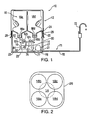
- a water delivery system 10 of the present invention which automatically and sequentially delivers water.
- the system 10 includes a dispenser 12 within which is a reservoir 14 for holding water 16, a plurality of containers, such as five gallon bottles, generally designated by the reference numeral 18, which are held in position above reservoir 14, and a pump 17 for delivering the water from the reservoir 14 to one or more sources or outlets, as will be explained later, in greater detail.
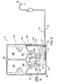
- the dispenser 12 includes a housing 20 having a bin 21, a separate base 22 upon which the reservoir 14 and the pump 17 are removably mounted, a tray 24 suspended above the reservoir 14 which holds the bottles 18, and a removable cover 26 which encloses the bottles 18.
- the base 22 and the tray 26 are held in spaced relationship by posts 28 which are positioned within the bin 21 and which are removably bolted to the components 22 and 26.
- the bin 21 has a bottom wall 25 upon which the base 22 normally rests, and four equal side walls 30 which extend upwardly and about the reservoir 14.
- the system 10 holds four bottles 18a, b, c and d, wherein each bottle has a body 32 for holding the water and a neck 34 with a capped opening 36 from which the bottled water is delivered (Fig. 4).
- the illustrated bottles 18 also have ergonomic features as disclosed in United States Design Patent Application, Serial No. 83,183, filed January 23, 1998, now U.S. Design Patent 404, 649, issued January 26, 1999.
- the tray 24 includes receptacles 38 for the bottles 18a-d (Fig. 4).
- the receptacles 38 have inwardly inclined surfaces 39 with downwardly extending spouts 40 contoured to support and receive the similarly contoured portions and tapered necks of the bottles 18 (Fig. 3).
- the spouts 40 are positioned above the reservoir 14.
- the tray 24 also has an outer depending wall 46 with a lower outwardly extending flange 48 that can rest on an outwardly extending flange 50 extending from the walls 30 at the top of the bin 21.
- the cover 26 has a lower outwardly extending flange 52 which can rest on the flange 48 of the tray 24, and the described three flanges can be releasably secured together.
- the described assembly has a nesting or sealing relationship for hygienic purposes while, at the same time, its components readily can be separated or disassembled.
- the reservoir 14 as shown in Figs. 3 and 4 is circular and is hygienically sealed by a removable lid 56 (Figs. 1, 3 and 4) which has four spaced apart ports 58 a, b, c and d extending therethrough (Fig. 3).
- the reservoir has a capacity of about 7.57l (2 gallons).
- the dispenser 12 has a unit 60 for automatically and sequentially dispensing water, preferably from one of the illustrated bottles 18a-d at a time.
- the dispensing unit includes conduits 62a, b, c and d of different lengths connected at one end into the inverted capped bottles and extending, at the other end, into the reservoir 14 to different depths.
- Each conduit 62a-d comprises an upper flexible tube 64a-d and a lower rigid tube 65a-d.
- Each flexible tube 64a-d has an upper end connected to an inverted bottle 18a-d via a probe 66 through which water can flow.
- each probe 66 includes a flow through opening 69 with an outer contoured guide 70, which slidably fits in a spout 40.
- the probe 66 engages and unseats the plug 68, to thereby allow the flow of water from the bottle 18, through the opening 69 and the probe 66 into the flexible tube 64 of the conduit 62.
- the lower ends of the flexible tubes 64a-d are connected to the upper ends of the rigid tubes 68a-d. As particularly shown in Fig. 3, the rigid tubes 68a-d slidably fit in and extend through the ports 58a-d of the reservoir lid 56.
- the upper ends of the rigid tubes 65a-d are of the same height relative to one another and they are directed to their respective bottles 18a-d.
- the lower ends of the rigid tubes 65a-d having openings 63a-d and extend into the reservoir 14 to different depths relative to their differing lengths.
- the water initially can flow from the bottles 18 until the reservoir 14 is filled up to, and including, the lower openings 63a-d of the conduits 62a and b.
- the water pressure prevents the flow of water 16 from the bottles 18c and d via conduits 62c and d.
- there is no such restricting pressure that is, water pressure
- the contents of the bottles 18a and b are free to flow into the reservoir 14 until the bottom openings 63a and b of the conduits 62a and b are below the water level in the reservoir 14.
- the surface or water level again can drop below the lower opening 63a of the conduit 62a until the bottle 18a is emptied and next below the lower opening 63b of the conduit 62b until the bottle 18b is emptied.
- the water will drop below the lower openings 63c and 63d of the conduits 62c and d (that is after the bottles 18a and b have been emptied).
- the restrictive water pressure has been removed and water will flow first from the bottle 18c through the conduit 62c and then when the restrictive water pressure has been removed from the conduit 62d, the water from bottle 18d will flow through the conduit 62d into the reservoir 14.
- the number of bottles 18 used can differ (e.g., 2, 3, 5 or 6) and the respective number and lengths of the conduits 62 will respectively differ.
- the dispensing unit 60 will continue to provide a controlled, automatic and sequential emptying of the bottles 18 into the reservoir 14.
- a delivery unit 71 For delivering water received by the reservoir 14, a delivery unit 71 is provided (Fig. 1).
- the unit 71 provides the water 16 from the reservoir to one or more outlets 72.
- the delivery unit 71 includes a supply line or conduit 77 connected at one end to an outlet opening 74 in the lower portion of the reservoir 14 and connected at its other end to the pump 17.
- the pump 17 has a pressure switch 76.
- the pump 17 is designed to pump the desired amount of water to one or more outlets 72 via a supply line or conduit 78.
- a pump which provides 3.78 to 11.35 l/mn (1.0 to 3.0 gallons per minute) of water through the supply line 78 to an outlet 72 (e.g., a faucet) has been found to be satisfactory.
- Suitable pumps are marketed by Aquatech Water Systems of Irvine, California such as models from its CDP series.
- the pump 17 is connected to the supply line or conduit 78 which is connected to one or more outlets 72, such as water faucets, refrigerator ice makers and water dispensers, coffee makers or other means for dispensing or using liquids, such as bottled water.
- outlets 72 such as water faucets, refrigerator ice makers and water dispensers, coffee makers or other means for dispensing or using liquids, such as bottled water.
- the pressure switch 76 senses a change in pressure within the appropriate supply line 78, that is, that the pressure within such supply line 78 decreases. This normally causes actuation of the pump 17 to pump water from the reservoir 14 to the outlet 72.
- the pump 17 Once the outlet 72 is closed, such that the flow of water is terminated, the pump 17 normally will continue to remove water from reservoir 14 until the pressure within the supply line 78 is increased to a predetermined level.
- the pressure switch 76 senses the same and automatically deactivates the pump 17.
- the system 10 can continue to operate in this manner until the water in reservoir 14 reaches a predetermined level. At this point, the system 10 will halt operation regardless of the demand until a full bottle or bottles 18 replace the empty ones. At that point, normal operation can resume.
- one or more of the supply lines 78 are pressurized only as long as the water from the reservoir 14 is above or at a predetermined level, such as at about 1.5 quarts. When the water in the reservoir 14 drops below that level the water flow stops.
- the "shut-off" reservoir level is maintained by the device 80 shown in Figures 3 and 7.
- the device 80 includes a pair of probes 82 and 84 extending into the reservoir 14 at the desired shut off or predetermined level, and an electrical source 86 is connected to the probes 82 and 84 and to the pump 17.
- the current flows from the source 86 to the lower probe 82 and to the upper probe 84 via the water therebetween, and then from the upper probe 84 to the pump 74 and to the electrical source 86.
- the circuit is broken because the current cannot flow between the probes 82 and 84 and the operation of the pump 17 is halted.
- an indicating device 88 can be used which includes a float switch 90 in the reservoir 14.
- the float switch 90 is connected to a LED 92.
- the float switch 90 closes a circuit and illuminates the LED 92 to advise that the water supply should be replenished before the water drops to the shut off level.
- control or indicating devices of the present invention such as devices 80 and 88 can be used separately or together.
- an indicator e.g., the LED 92
- the cover 26 can be removed, the empty bottles, e.g., 18a, b and c, should be removed and replaced by filled bottles. All this can be alone while the bottle 18d is still providing water to the reservoir 14.
- the system 10 can continue to provide water without interruption.
- the partially emptied bottle 18d also can be used in place of an empty bottle, e.g., 18a, as long as sufficient water is in the reservoir 14 during the change over.
- maintaining the water in the reservoir at least at a predetermined level prevents emptying of the reservoir and having the pump 17 run dry which would then require at least priming of the pump before resuming normal operation.
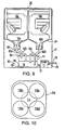
- FIG. 9 and 10 there is shown another embodiment of the dispenser 10.
- the dispenser 12 of Figures 9 and 10 is similar to the embodiment shown in Figures 1-4. In this instance, however, the bin 21 and tray 24 are integral.
- FIG. 11-13 there is shown another embodiment of the present invention which sequentially dispenses water from the containers 18a-d.
- the conduits 93a-d have open ends and are of the same length, and the containers 18a-d are positioned at different heights.
- the containers 18a-d generally can maintain their side by side relationship, but they are coextensive only along portions of their heights or lengths.
- the system 10 with conduits 93a-d of equal lengths effectively operates the same way as the system 10 of Fig. 1 (in which the containers 18a-d are at the same height and the lengths of the conduits 62a-d differ).
- the containers 18a-d are maintained at different heights by the tray 94 which, in this case, has receptacles 95a-d of different heights for the bottles 18a-d (Fig. 13).
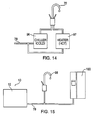
- FIG. 14 there is shown a system 10 which includes a supply conduit 78 connected to a chiller 96 and a heater 97 to deliver water to the faucet 72 at a desired temperature.
- FIG. 15 these figures illustrate systems 10 for delivering water to multiple outlets 72.
- the water from the system 10 is supplied to a faucet 98 and a refrigerator 100 (ice maker and water dispenser); in Figure 16, the system 10 is maintained at one level (e.g., the basement) and delivers the water to another level (kitchen) which multiple outlets are located (faucet 98 and refrigerator 100); and in Fig. 17, the system 10 is maintained at a remote location (e.g., a storeroom) and provides water to a coffee maker 102 and a water fountain 104 in another room, such as may be found in homes, commercial and industrial buildings, restaurants and other establishments.
- a remote location e.g., a storeroom
Landscapes
- Engineering & Computer Science (AREA)
- Mechanical Engineering (AREA)
- Devices For Dispensing Beverages (AREA)
- Filling Of Jars Or Cans And Processes For Cleaning And Sealing Jars (AREA)
- Quick-Acting Or Multi-Walled Pipe Joints (AREA)
- Pipeline Systems (AREA)
- Infusion, Injection, And Reservoir Apparatuses (AREA)
- External Artificial Organs (AREA)
- Feeding, Discharge, Calcimining, Fusing, And Gas-Generation Devices (AREA)
Abstract
Description
which has the capacity to provide comparatively substantial quantities of liquids (e.g., water) by using a plurality of relatively large containers, which has the capability of providing liquid to one or more outlets, which can be maintained at different locations near or remote from the one or more liquid outlets, which can be replenished easily and on a less frequent basis, and which can operate automatically and continuously. In accordance with the present invention, the system includes a dispenser for holding a plurality of containers (e.g., five gallon bottles of water) at a desired location relative to the one or more outlets, and a unit for automatically and sequentially dispensing the liquid from one or more (but not all) of the containers. The containers are held by the dispenser generally along side one another, and the dispensing unit is connected to each container and dispenses the liquid from the containers in a sequential manner. For example, when a container becomes depleted the next container is ready and can supply liquid without interruption. The unit dispenses the liquid into a reservoir which holds the liquid provided by the containers. Preferably, the system holds the containers above the reservoir in an inverted manner such that their openings are facing downward toward the reservoir. The system also can include a pump for conveying liquid from the reservoir to at least one other outlet, such as a faucet.
Claims (13)
- A system (10) for delivering liquid held in containers, comprising:a dispenser (12) for holding a plurality of containers (18a, 18b) in a generally side by side and adjacent relationship, and for releasing the containers when the containers generally are empty and are ready to be replaced by new containers;a dispensing unit (60) connected to each of the containers for sequentially dispensing the liquid from the containers held by said dispenser, said dispensing unit including a plurality of conduits (62a, 62b), each conduit being coupled to an opening of one of the plurality of containers; anda reservoir (14) connected to the containers by said dispensing unit such that each of the plurality of conduits extends within said reservoir, the reservoir including a chamber, the reservoir receiving the liquid sequentially dispensed by said unit and holding the liquid ready for use, each conduit emptying directly into the chamber.
- The system of claim 1, wherein the containers have openings (36) therein for the flow of liquid therethrough, and wherein said dispenser includes receptacles (38) positioned above said reservoir for releasably holding the containers with their openings positioned in the direction of said reservoir.
- The system of claim 2, wherein said conduits have openings (63a, 63b) for the sequential dispensing of the liquid from the containers into said reservoir and wherein at least one of said conduits has an opening which is located at a different depth from the openings of the other containers.
- The system of claim 3, wherein said receptacles hold the containers at the same height above said reservoir, and wherein said conduits are of different lengths and said openings therein are at the ends of said conduits.
- The system of claim 3, wherein said receptacles hold the containers at different heights above said reservoir, and wherein said conduits are of the same length and said openings therein are at the ends of said conduits.
- The system of any preceding claim, wherein said system further comprises a unit (71) connected to said reservoir and at least one outlet (72) for delivering liquid from said reservoir upon demand by and to said outlet.
- The system of claim 6, wherein said delivery unit is connected to a plurality of outlets for delivering liquid upon demand by any or all of said outlets.
- The system of any preceding claim, wherein said system includes a device (88) operatively connected to said reservoir which indicates when the level of the liquid in said reservoir reaches a predetermined level.
- The system of claim 8, wherein said system includes a device (80) operatively connected to said reservoir which halts the further flow of liquid from said reservoir when the level of the liquid in said reservoir drops below a predetermined level.
- A system (10) for delivering liquids held in containers having openings for the flow of liquid therefrom, comprising:a dispenser (12) for releasably holding the containers (18a, 18b) in a generally side by side and adjacent relationship with the containers' openings (36) positioned to discharge liquids therefrom;a reservoir (14) spaced from the containers' openings, the reservoir including a chamber, the reservoir receiving and holding the contents of the containers;a unit (60) having conduits (62a, 62b) which are connected at one end to the openings in the containers and which extend directly into said chamber and wherein said other ends have openings (63a, 63b) therein at different depths for sequentially dispensing the liquids from the containers directly into said chamber as said openings of said conduits in said chamber become uncovered as the liquid level therein sequentially drops below said conduit openings;a unit (71) operatively connected to said reservoir and an outlet (72) for delivering liquid from said reservoir upon demand to said outlet; anda device (88) operatively connected to said reservoir which indicates when the level of the liquid in said reservoir drops to a predetermined level, to thereby allow for the removal of generally emptied containers releasably held by said dispenser and for replacement of the generally emptied containers with filled ones.
- The system of any one of claims 6, 7 and 10, wherein the liquid flows from the reservoir to the at least one outlet via gravity.
- The system of any one of claims 6, 7 and 10, wherein the liquid flows from the reservoir to the at least one outlet via a pump (17).
- The system of any preceding claim, wherein the liquid is water.
Priority Applications (1)
| Application Number | Priority Date | Filing Date | Title |
|---|---|---|---|
| DK99937509T DK1100721T5 (en) | 1998-07-29 | 1999-07-27 | Liquid dispensing system from parallel containers |
Applications Claiming Priority (3)
| Application Number | Priority Date | Filing Date | Title |
|---|---|---|---|
| US124433 | 1998-07-29 | ||
| US09/124,433 US6059146A (en) | 1998-07-29 | 1998-07-29 | Liquid delivery system that automatically delivers liquid from a plurality of containers |
| PCT/US1999/016946 WO2000006451A1 (en) | 1998-07-29 | 1999-07-27 | Plural liquid delivery system |
Publications (4)
| Publication Number | Publication Date |
|---|---|
| EP1100721A1 EP1100721A1 (en) | 2001-05-23 |
| EP1100721A4 EP1100721A4 (en) | 2001-10-17 |
| EP1100721B1 EP1100721B1 (en) | 2003-05-21 |
| EP1100721B9 true EP1100721B9 (en) | 2004-01-21 |
Family
ID=22414855
Family Applications (1)
| Application Number | Title | Priority Date | Filing Date |
|---|---|---|---|
| EP99937509A Expired - Lifetime EP1100721B9 (en) | 1998-07-29 | 1999-07-27 | Device for dispensing liquid from side by side arranged containers |
Country Status (11)
| Country | Link |
|---|---|
| US (1) | US6059146A (en) |
| EP (1) | EP1100721B9 (en) |
| AT (1) | ATE240868T1 (en) |
| CA (1) | CA2338726A1 (en) |
| DE (1) | DE69908137T2 (en) |
| ES (1) | ES2199585T3 (en) |
| MX (1) | MXPA01001154A (en) |
| PL (1) | PL347035A1 (en) |
| PT (1) | PT1100721E (en) |
| SE (1) | SE1100721T5 (en) |
| WO (1) | WO2000006451A1 (en) |
Families Citing this family (10)
| Publication number | Priority date | Publication date | Assignee | Title |
|---|---|---|---|---|
| US6269980B1 (en) * | 1999-11-08 | 2001-08-07 | David M Randall | Portable beverage dispenser |
| WO2003016198A1 (en) * | 2001-08-15 | 2003-02-27 | Big Bottle I.P. Pty Ltd | Liquid dispensing system and apparatus |
| US6715514B2 (en) | 2002-09-07 | 2004-04-06 | Worldwide Liquids | Method and apparatus for fluid transport, storage and dispensing |
| DE202004001038U1 (en) * | 2004-01-24 | 2004-04-08 | Delle Vedove Maschinenbau Gmbh | Tandem piston Schmelzer |
| GB2422366A (en) * | 2005-01-22 | 2006-07-26 | Rls Concepts Ltd | Beverage dispensing system |
| US20060226170A1 (en) * | 2005-04-08 | 2006-10-12 | Larsen Gregory K | Method and apparatus for delivering bottled water to an automatic ice maker and water chiller |
| US7793795B2 (en) * | 2006-03-20 | 2010-09-14 | The United States Of America As Represented By The Secretary Of The Army | Liquid storage and delivery assembly |
| JP2009012821A (en) * | 2007-07-05 | 2009-01-22 | Unitech Medical Co Ltd | Water supply appliance for water server |
| WO2012129686A1 (en) * | 2011-03-25 | 2012-10-04 | Vandersteen Colleen Beth | Sustainable bulk liquid dispensing device |
| KR20140075291A (en) * | 2012-12-11 | 2014-06-19 | 동부대우전자 주식회사 | Refrigerator |
Family Cites Families (11)
| Publication number | Priority date | Publication date | Assignee | Title |
|---|---|---|---|---|
| US1078214A (en) * | 1912-04-08 | 1913-11-11 | William C Coleston | Water-cooler. |
| US3927804A (en) * | 1973-04-30 | 1975-12-23 | Heiko T Deman | Liquid dispenser with multi-container reserves |
| US3896972A (en) * | 1973-07-09 | 1975-07-29 | Samuel W Neidore | Remote liquid distribution system |
| US3930598A (en) * | 1974-03-28 | 1976-01-06 | Bildon Company | Liquid dispensing apparatus |
| US4274557A (en) * | 1976-11-17 | 1981-06-23 | American Beverage Control | Beverage dispenser pumping system |
| US4406247A (en) * | 1982-07-30 | 1983-09-27 | Eastman Kodak Company | Adhesive dispensing system |
| US4601409A (en) * | 1984-11-19 | 1986-07-22 | Tritec Industries, Inc. | Liquid chemical dispensing system |
| US4699188A (en) * | 1986-01-17 | 1987-10-13 | Baker Henry E | Hygienic liquid dispensing system |
| US4903862A (en) * | 1987-10-13 | 1990-02-27 | Abc/Sebrn Tech. Corp., Inc. | Soft drink dispenser |
| CA1338210C (en) * | 1988-10-14 | 1996-04-02 | Henry E. Baker | Liquid container support and hygienic liquid dispensing system |
| US5105858A (en) * | 1990-11-19 | 1992-04-21 | Levinson Lionel R | Water dispenser bottle |
-
1998
- 1998-07-29 US US09/124,433 patent/US6059146A/en not_active Expired - Fee Related
-
1999
- 1999-07-27 DE DE69908137T patent/DE69908137T2/en not_active Expired - Fee Related
- 1999-07-27 EP EP99937509A patent/EP1100721B9/en not_active Expired - Lifetime
- 1999-07-27 ES ES99937509T patent/ES2199585T3/en not_active Expired - Lifetime
- 1999-07-27 SE SE99937509T patent/SE1100721T5/xx unknown
- 1999-07-27 PL PL99347035A patent/PL347035A1/en not_active Application Discontinuation
- 1999-07-27 AT AT99937509T patent/ATE240868T1/en not_active IP Right Cessation
- 1999-07-27 WO PCT/US1999/016946 patent/WO2000006451A1/en active IP Right Grant
- 1999-07-27 CA CA002338726A patent/CA2338726A1/en not_active Abandoned
- 1999-07-27 PT PT99937509T patent/PT1100721E/en unknown
- 1999-07-27 MX MXPA01001154A patent/MXPA01001154A/en not_active IP Right Cessation
Also Published As
| Publication number | Publication date |
|---|---|
| EP1100721A1 (en) | 2001-05-23 |
| DE69908137D1 (en) | 2003-06-26 |
| PT1100721E (en) | 2003-10-31 |
| SE1100721T5 (en) | 2004-01-20 |
| CA2338726A1 (en) | 2000-02-10 |
| ES2199585T3 (en) | 2004-02-16 |
| EP1100721A4 (en) | 2001-10-17 |
| WO2000006451A1 (en) | 2000-02-10 |
| US6059146A (en) | 2000-05-09 |
| EP1100721B1 (en) | 2003-05-21 |
| SE1100721T3 (en) | 2003-09-02 |
| DE69908137T2 (en) | 2004-03-25 |
| PL347035A1 (en) | 2002-03-11 |
| MXPA01001154A (en) | 2002-08-20 |
| ATE240868T1 (en) | 2003-06-15 |
Similar Documents
| Publication | Publication Date | Title |
|---|---|---|
| US6926170B2 (en) | Drink dispensing cart and water packaging and supply system | |
| US7083071B1 (en) | Drink supply canister for beverage dispensing apparatus | |
| US6766656B1 (en) | Beverage dispensing apparatus | |
| US6896159B2 (en) | Beverage dispensing apparatus having fluid director | |
| US7004355B1 (en) | Beverage dispensing apparatus having drink supply canister holder | |
| US4898303A (en) | Cup-type drink merchandiser with bag-in-box product supply system | |
| US6827243B1 (en) | Portable liquid dispensing kit | |
| EP1100721B9 (en) | Device for dispensing liquid from side by side arranged containers | |
| US6434966B1 (en) | Self-contained liquid storage, delivery, and automatic fill apparatus and method | |
| GB2160847A (en) | Tapping device for postmixed drinks | |
| US4955509A (en) | Dispensing of liquids | |
| US4892125A (en) | System for serving a pre-mix beverage or making and serving a post-mix beverage in the zero gravity conditions of outer space | |
| US4238053A (en) | Device for dispensing chilled liquid | |
| KR20200136413A (en) | Remotely controlled beverage dispensing system | |
| CN112789236A (en) | Liquid dispenser for dispensing water and flavored beverages | |
| GB2268925A (en) | Beverage dispenser. | |
| US11952259B2 (en) | Beverage dispensing system | |
| US20050150824A1 (en) | Water filtration tank dispensing system | |
| CN111067362B (en) | Liquid milk supply device and self-service coffee machine | |
| WO2023023117A2 (en) | System for dispensing liquid from inverted container | |
| KR20040066965A (en) | Beverage SuppIy Device |
Legal Events
| Date | Code | Title | Description |
|---|---|---|---|
| PUAI | Public reference made under article 153(3) epc to a published international application that has entered the european phase |
Free format text: ORIGINAL CODE: 0009012 |
|
| 17P | Request for examination filed |
Effective date: 20010220 |
|
| AK | Designated contracting states |
Kind code of ref document: A1 Designated state(s): AT BE CH CY DE DK ES FI FR GB GR IE IT LI LU MC NL PT SE |
|
| A4 | Supplementary search report drawn up and despatched |
Effective date: 20010904 |
|
| AK | Designated contracting states |
Kind code of ref document: A4 Designated state(s): AT BE CH CY DE DK ES FI FR GB GR IE IT LI LU MC NL PT SE |
|
| RIC1 | Information provided on ipc code assigned before grant |
Free format text: 7B 65B 1/04 A, 7B 67D 3/00 B, 7B 67D 1/00 B |
|
| 17Q | First examination report despatched |
Effective date: 20020215 |
|
| GRAH | Despatch of communication of intention to grant a patent |
Free format text: ORIGINAL CODE: EPIDOS IGRA |
|
| RTI1 | Title (correction) |
Free format text: DEVICE FOR DISPENSING LIQUID FROM SIDE BY SIDE ARRANGED CONTAINERS |
|
| GRAH | Despatch of communication of intention to grant a patent |
Free format text: ORIGINAL CODE: EPIDOS IGRA |
|
| GRAA | (expected) grant |
Free format text: ORIGINAL CODE: 0009210 |
|
| AK | Designated contracting states |
Designated state(s): AT BE CH CY DE DK ES FI FR GB GR IE IT LI LU MC NL PT SE |
|
| REG | Reference to a national code |
Ref country code: GB Ref legal event code: FG4D |
|
| REG | Reference to a national code |
Ref country code: CH Ref legal event code: EP |
|
| REG | Reference to a national code |
Ref country code: IE Ref legal event code: FG4D |
|
| REF | Corresponds to: |
Ref document number: 69908137 Country of ref document: DE Date of ref document: 20030626 Kind code of ref document: P |
|
| RAP2 | Party data changed (patent owner data changed or rights of a patent transferred) |
Owner name: NESTLE WATERS NORTH AMERICA HOLDINGS INC. |
|
| REG | Reference to a national code |
Ref country code: CH Ref legal event code: NV Representative=s name: MICHELI & CIE INGENIEURS-CONSEILS |
|
| NLT2 | Nl: modifications (of names), taken from the european patent patent bulletin |
Owner name: NESTLE WATERS NORTH AMERICA HOLDINGS INC. |
|
| REG | Reference to a national code |
Ref country code: SE Ref legal event code: TRGR |
|
| REG | Reference to a national code |
Ref country code: DK Ref legal event code: T3 |
|
| REG | Reference to a national code |
Ref country code: GR Ref legal event code: EP Ref document number: 20030403221 Country of ref document: GR |
|
| REG | Reference to a national code |
Ref country code: SE Ref legal event code: RPOT |
|
| REG | Reference to a national code |
Ref country code: ES Ref legal event code: FG2A Ref document number: 2199585 Country of ref document: ES Kind code of ref document: T3 |
|
| ET | Fr: translation filed | ||
| PLBE | No opposition filed within time limit |
Free format text: ORIGINAL CODE: 0009261 |
|
| STAA | Information on the status of an ep patent application or granted ep patent |
Free format text: STATUS: NO OPPOSITION FILED WITHIN TIME LIMIT |
|
| NLR4 | Nl: receipt of corrected translation in the netherlands language at the initiative of the proprietor of the patent | ||
| 26N | No opposition filed |
Effective date: 20040224 |
|
| ET1 | Fr: translation filed ** revision of the translation of the patent or the claims | ||
| PGFP | Annual fee paid to national office [announced via postgrant information from national office to epo] |
Ref country code: GB Payment date: 20040719 Year of fee payment: 6 Ref country code: FI Payment date: 20040719 Year of fee payment: 6 |
|
| PGFP | Annual fee paid to national office [announced via postgrant information from national office to epo] |
Ref country code: MC Payment date: 20040720 Year of fee payment: 6 Ref country code: IE Payment date: 20040720 Year of fee payment: 6 |
|
| PGFP | Annual fee paid to national office [announced via postgrant information from national office to epo] |
Ref country code: PT Payment date: 20040721 Year of fee payment: 6 Ref country code: GR Payment date: 20040721 Year of fee payment: 6 |
|
| PGFP | Annual fee paid to national office [announced via postgrant information from national office to epo] |
Ref country code: BE Payment date: 20040722 Year of fee payment: 6 |
|
| PGFP | Annual fee paid to national office [announced via postgrant information from national office to epo] |
Ref country code: SE Payment date: 20040723 Year of fee payment: 6 |
|
| PGFP | Annual fee paid to national office [announced via postgrant information from national office to epo] |
Ref country code: ES Payment date: 20040726 Year of fee payment: 6 |
|
| PGFP | Annual fee paid to national office [announced via postgrant information from national office to epo] |
Ref country code: FR Payment date: 20040729 Year of fee payment: 6 |
|
| PGFP | Annual fee paid to national office [announced via postgrant information from national office to epo] |
Ref country code: DK Payment date: 20040730 Year of fee payment: 6 Ref country code: AT Payment date: 20040730 Year of fee payment: 6 |
|
| PGFP | Annual fee paid to national office [announced via postgrant information from national office to epo] |
Ref country code: CH Payment date: 20040804 Year of fee payment: 6 |
|
| PGFP | Annual fee paid to national office [announced via postgrant information from national office to epo] |
Ref country code: CY Payment date: 20040806 Year of fee payment: 6 |
|
| PGFP | Annual fee paid to national office [announced via postgrant information from national office to epo] |
Ref country code: NL Payment date: 20040823 Year of fee payment: 6 |
|
| PGFP | Annual fee paid to national office [announced via postgrant information from national office to epo] |
Ref country code: DE Payment date: 20040902 Year of fee payment: 6 |
|
| REG | Reference to a national code |
Ref country code: DK Ref legal event code: T5 |
|
| PGFP | Annual fee paid to national office [announced via postgrant information from national office to epo] |
Ref country code: LU Payment date: 20041209 Year of fee payment: 6 |
|
| PG25 | Lapsed in a contracting state [announced via postgrant information from national office to epo] |
Ref country code: FI Free format text: LAPSE BECAUSE OF NON-PAYMENT OF DUE FEES Effective date: 20050710 |
|
| PG25 | Lapsed in a contracting state [announced via postgrant information from national office to epo] |
Ref country code: LU Free format text: LAPSE BECAUSE OF NON-PAYMENT OF DUE FEES Effective date: 20050727 Ref country code: IT Free format text: LAPSE BECAUSE OF NON-PAYMENT OF DUE FEES Effective date: 20050727 Ref country code: IE Free format text: LAPSE BECAUSE OF NON-PAYMENT OF DUE FEES Effective date: 20050727 Ref country code: GB Free format text: LAPSE BECAUSE OF NON-PAYMENT OF DUE FEES Effective date: 20050727 Ref country code: AT Free format text: LAPSE BECAUSE OF NON-PAYMENT OF DUE FEES Effective date: 20050727 |
|
| PG25 | Lapsed in a contracting state [announced via postgrant information from national office to epo] |
Ref country code: SE Free format text: LAPSE BECAUSE OF NON-PAYMENT OF DUE FEES Effective date: 20050728 Ref country code: ES Free format text: LAPSE BECAUSE OF NON-PAYMENT OF DUE FEES Effective date: 20050728 |
|
| PG25 | Lapsed in a contracting state [announced via postgrant information from national office to epo] |
Ref country code: MC Free format text: LAPSE BECAUSE OF NON-PAYMENT OF DUE FEES Effective date: 20050731 Ref country code: LI Free format text: LAPSE BECAUSE OF NON-PAYMENT OF DUE FEES Effective date: 20050731 Ref country code: CH Free format text: LAPSE BECAUSE OF NON-PAYMENT OF DUE FEES Effective date: 20050731 Ref country code: BE Free format text: LAPSE BECAUSE OF NON-PAYMENT OF DUE FEES Effective date: 20050731 |
|
| PG25 | Lapsed in a contracting state [announced via postgrant information from national office to epo] |
Ref country code: DK Free format text: LAPSE BECAUSE OF NON-PAYMENT OF DUE FEES Effective date: 20050801 |
|
| PG25 | Lapsed in a contracting state [announced via postgrant information from national office to epo] |
Ref country code: PT Free format text: LAPSE BECAUSE OF NON-PAYMENT OF DUE FEES Effective date: 20060127 |
|
| PG25 | Lapsed in a contracting state [announced via postgrant information from national office to epo] |
Ref country code: NL Free format text: LAPSE BECAUSE OF NON-PAYMENT OF DUE FEES Effective date: 20060201 Ref country code: DE Free format text: LAPSE BECAUSE OF NON-PAYMENT OF DUE FEES Effective date: 20060201 |
|
| PG25 | Lapsed in a contracting state [announced via postgrant information from national office to epo] |
Ref country code: GR Free format text: LAPSE BECAUSE OF NON-PAYMENT OF DUE FEES Effective date: 20060202 |
|
| REG | Reference to a national code |
Ref country code: CH Ref legal event code: PL |
|
| EUG | Se: european patent has lapsed | ||
| GBPC | Gb: european patent ceased through non-payment of renewal fee |
Effective date: 20050727 |
|
| PG25 | Lapsed in a contracting state [announced via postgrant information from national office to epo] |
Ref country code: FR Free format text: LAPSE BECAUSE OF NON-PAYMENT OF DUE FEES Effective date: 20060331 |
|
| NLV4 | Nl: lapsed or anulled due to non-payment of the annual fee |
Effective date: 20060201 |
|
| REG | Reference to a national code |
Ref country code: DK Ref legal event code: EBP |
|
| REG | Reference to a national code |
Ref country code: IE Ref legal event code: MM4A |
|
| REG | Reference to a national code |
Ref country code: FR Ref legal event code: ST Effective date: 20060331 |
|
| REG | Reference to a national code |
Ref country code: ES Ref legal event code: FD2A Effective date: 20050728 |
|
| BERE | Be: lapsed |
Owner name: *NESTLE WATERS NORTH AMERICA HOLDINGS INC. Effective date: 20050731 |