EP1093254A2 - Virtual private network management system - Google Patents

Virtual private network management system Download PDF

Info

Publication number
EP1093254A2
EP1093254A2 EP00308989A EP00308989A EP1093254A2 EP 1093254 A2 EP1093254 A2 EP 1093254A2 EP 00308989 A EP00308989 A EP 00308989A EP 00308989 A EP00308989 A EP 00308989A EP 1093254 A2 EP1093254 A2 EP 1093254A2
Authority
EP
European Patent Office
Prior art keywords
network device
network
given
message
network devices
Prior art date
Legal status (The legal status is an assumption and is not a legal conclusion. Google has not performed a legal analysis and makes no representation as to the accuracy of the status listed.)
Withdrawn
Application number
EP00308989A
Other languages
German (de)
French (fr)
Other versions
EP1093254A3 (en
Inventor
Loa Andersson
Tove Madsen
Marcel Wiget
Current Assignee (The listed assignees may be inaccurate. Google has not performed a legal analysis and makes no representation or warranty as to the accuracy of the list.)
Nortel Networks Ltd
Original Assignee
Nortel Networks Ltd
Priority date (The priority date is an assumption and is not a legal conclusion. Google has not performed a legal analysis and makes no representation as to the accuracy of the date listed.)
Filing date
Publication date
Application filed by Nortel Networks Ltd filed Critical Nortel Networks Ltd
Publication of EP1093254A2 publication Critical patent/EP1093254A2/en
Publication of EP1093254A3 publication Critical patent/EP1093254A3/en
Withdrawn legal-status Critical Current

Links

Images

Classifications

    • HELECTRICITY
    • H04ELECTRIC COMMUNICATION TECHNIQUE
    • H04LTRANSMISSION OF DIGITAL INFORMATION, e.g. TELEGRAPHIC COMMUNICATION
    • H04L41/00Arrangements for maintenance, administration or management of data switching networks, e.g. of packet switching networks
    • H04L41/28Restricting access to network management systems or functions, e.g. using authorisation function to access network configuration
    • HELECTRICITY
    • H04ELECTRIC COMMUNICATION TECHNIQUE
    • H04LTRANSMISSION OF DIGITAL INFORMATION, e.g. TELEGRAPHIC COMMUNICATION
    • H04L12/00Data switching networks
    • H04L12/28Data switching networks characterised by path configuration, e.g. LAN [Local Area Networks] or WAN [Wide Area Networks]
    • H04L12/46Interconnection of networks
    • H04L12/4641Virtual LANs, VLANs, e.g. virtual private networks [VPN]
    • H04L12/4675Dynamic sharing of VLAN information amongst network nodes
    • H04L12/4679Arrangements for the registration or de-registration of VLAN attribute values, e.g. VLAN identifiers, port VLAN membership
    • HELECTRICITY
    • H04ELECTRIC COMMUNICATION TECHNIQUE
    • H04LTRANSMISSION OF DIGITAL INFORMATION, e.g. TELEGRAPHIC COMMUNICATION
    • H04L63/00Network architectures or network communication protocols for network security
    • H04L63/02Network architectures or network communication protocols for network security for separating internal from external traffic, e.g. firewalls
    • H04L63/0272Virtual private networks
    • HELECTRICITY
    • H04ELECTRIC COMMUNICATION TECHNIQUE
    • H04LTRANSMISSION OF DIGITAL INFORMATION, e.g. TELEGRAPHIC COMMUNICATION
    • H04L41/00Arrangements for maintenance, administration or management of data switching networks, e.g. of packet switching networks
    • H04L41/40Arrangements for maintenance, administration or management of data switching networks, e.g. of packet switching networks using virtualisation of network functions or resources, e.g. SDN or NFV entities

Abstract

An apparatus and method of managing a virtual private network having a set of network devices maintains a network device memory set for storing a set of network device identifiers that identifies each of the set of network devices. More particularly, a request to join the virtual private network is received from a given network device having a given network device identifier that identifies the given network device. The set of network device identifiers then is retrieved from the network device memory set to identify all network devices in the set of network devices. A notify message then is forwarded to each of the set of network devices, and a join message is forwarded to the given network device. The notify message includes the given network device identifier, while the join message includes the set of network device identifiers. The given network device identifier then is stored in the network device memory set.

Description

    FIELD OF THE INVENTION
  • The invention generally relates networks and, more particularly, the invention relates to managing a virtual private network.
  • BACKGROUND OF THE INVENTION
  • Although deployed across third party networks, virtual private networks have the look and feel of a private network, such as an intranet utilized by a private company. In fact, many currently utilized virtual private networks are deployed across the Internet to provide a private network solution at a relatively low cost.
  • A virtual private network ("VPN") often includes two or more preconfigured network devices that each act as VPN nodes in their VPN. To that end, each such network device typically is preconfigured with the address of all other network devices to be in their VPN, and preselected network routes (hereinafter "tunnels") between each of the other network devices in their VPN. By way of example, a given VPN that utilizes the Internet may include a first router with its associated local area network, and a second router with its associated local area network. The first router is preconfigured to have the Internet Protocol address of the second router, and a set of preselected network tunnels to the second router. In a similar manner, the second router is preconfigured to have the Internet Protocol address of the first router, and a set of preselected network tunnels to the first router. Accordingly, the two routers and the members of their respective local area networks communicate in their VPN across the Internet via the preselected network tunnels.
  • Problems arise, however, when network devices (e.g., routers) that are not preconfigured are to be added to a VPN that operates in the above described manner. Specifically, such network devices cannot be added to a VPN unless they are configured with the above noted preconfiguration data.
  • SUMMARY OF THE INVENTION
  • In accordance with one aspect of the invention, an apparatus and method of managing a virtual private network having a set of network devices maintains a network device memory set for storing a set of network device identifiers that identifies each of the set of network devices. More particularly, a request to join the virtual private network is received from a given network device having a given network device identifier that identifies the given network device. The set of network device identifiers then is retrieved from the network device memory set to identify all network devices in the set of network devices. A notify message then is forwarded to each of the set of network devices, and a join message is forwarded to the given network device. The notify message includes the given network device identifier, while the join message includes the set of network device identifiers. The given network device identifier then is stored in the network device memory set.
  • In response to receipt of the notify message, at least one of the set of network devices preferably communicates with the given network device to establish a communication tunnel with the given network device. In a similar manner, in response to receipt of the join message, the given network device preferably communicates with at least one of the network devices in the set of network devices to establish a communication tunnel with the at least one of the set of network devices. Among other data, the request may include a network identifier identifying the given virtual private network. In alternative embodiments, the total number of network devices in the set of network devices may equal zero. In such case, the network device memory set may be a database that is established for the given virtual private network in response to receipt of the request.
  • In some embodiments, the apparatus and method authenticate the request to confirm the identity of the given network device. The request may be received from a packet based network, and the network identifier may be an Internet Protocol address. Moreover, among other data, the join message and notify message may include data identifying the given virtual private network. In some embodiments, the apparatus and method generate the notify and join messages.
  • A remove message may be received from a remove network device. Once received, all network device identifiers again may be retrieved from the network device memory set, and a first message may be forwarded to all network devices identified by the retrieved network device identifiers. Each first message may include a remove identifier identifying the remove network device. In addition, in response to receipt of the first message, at least one of the network devices in the set of network devices disconnects a communication tunnel between the at least one network device and the remove network device. A second message that includes the retrieved network device identifiers may be forwarded to the remove network device.
  • In accordance with another aspect of the invention, a method of managing a virtual private network (having a set of member network devices each identified by a device identifier) maintains a storage device with the device identifier of each member. The storage device is updated as network devices are added to and removed from the virtual private network. Accordingly, in response to receipt of a request to join the virtual private network (from a given network device having a given network device identifier and data identifying the virtual private network), a notify message and join message are generated. The notify message has the given network device identifier, while the join message has the device identifiers in the storage device. The notify message then is forwarded to each of the set of network devices, and the join message is forwarded to the given network device.
  • BRIEF DESCRIPTION OF THE DRAWINGS
  • The foregoing and advantages of the invention will be appreciated more fully from the following further description thereof with reference to the accompanying drawings wherein:
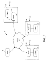
  • Figure 1 schematically shows an exemplary network arrangement in which illustrative embodiments of the invention may be implemented.
  • Figure 2 schematically shows a manager server that manages virtual private networks in accordance with illustrative embodiments of the invention.
  • Figure 3 schematically shows an illustrative database that may be in data storage for storing data relating to various VPNs.
  • Figure 4 shows an illustrative process of establishing and maintaining a VPN in accordance with illustrative embodiments of the invention.
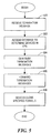
  • Figure 5 shows an illustrative process utilized by the manager server in figure 2 for removing a router from a VPN.
  • DESCRIPTION OF ILLUSTRATIVE EMBODIMENTS
  • Figure 1 schematically shows an exemplary network arrangement that may be utilized to implement a virtual private network ("VPN") configured in accordance with illustrative embodiments of the invention. Specifically, the network 10 includes a plurality of local area networks 12 that each communicate with a VPN manager server ("manager server 14") via the Internet 16. The manager server 14 may be a single server, or a cluster of cooperating servers. In fact, the manager server 14 need not be a part of any VPN. For example, the manager server 14 may be utilized as a third party service that establishes, maintains, and terminates VPNs for any set of network devices (e.g., routers).
  • Each local area network 12 includes one or more conventional routers 18 and a plurality of coupled clients 20. The clients 20 each may be any type of well known network device, such as a personal computer or server. Of course, each router 18 includes the logic for cooperating with the other network devices (i.e., the other routers 18 and the manager server 14) to establish VPNs in accordance with illustrative embodiments of the invention.
  • In some embodiments, the routers 18 and manager server 14 cooperate to establish, maintain, and terminate VPNs in a manner that permits routers 18 and other network devices to join VPNs without having, in advance, special preconfigured tunnels and special preconfigured VPN membership lists. More particularly, as discussed in greater detail below, network devices joining a specified VPN are given a current list of members of the specified VPN upon joining. Accordingly, joining network devices are not required to have the identity of all such members preconfigured in their memory prior to joining. This permits membership in VPNs to be dynamically changed with relative ease. Moreover, the various tunnels utilized for transmitting data between the member network devices can be dynamically established by the existing member network devices and joining devices at the time that the joining network devices join the VPN. This enables the member network devices to establish optimal tunnels based upon current network conditions and thus, not based upon preconfigured tunnels that may be less efficient.
  • As shown in figure 2, the manager server 14 includes various modules for managing the membership of any VPN that may be established across the network in accord with illustrative embodiments of the invention. The manager server 14 may simultaneously manage any number of VPNs, such as one VPN, or hundreds of VPNs. To that end, the manager server 14 includes data storage 22 (e.g., a database) for storing information relating to one or more VPNs, a parser 23 for parsing data from received messages, a message generator 24 for generating messages identifying members of the various VPNs managed by the manager server 14, and VPN logic 26 for managing the various VPNs and retrieving data from the database. The manager server 14 also includes an input port 28 for receiving data from the Internet 16, and an output port 30 for forwarding data to the various routers 18 across the Internet 16. Details of the interaction of these manager server modules are discussed below with reference to figures 4 and 5.
  • Figure 3 schematically shows a preferred VPN database ("database 22a") in the data storage 22. In particular, the database 22a includes a plurality of lists of data that each relate to one VPN. For example, the database 22a shown includes data relating to a total of Z VPNs that each are managed by the manager server 14. Each VPN has an associated VPN identification code, security data relating to the VPN, and a list of network devices (i.e., routers 18) that are members of the specified VPN. Among other things, the security data may include authentication data for authenticating routers 18 attempting to access the VPN, such as encryption keys an/or passwords.
  • Figure 4 shows an illustrative process utilized by the manager server 14 for establishing and maintaining a VPN in accordance with illustrative embodiments of the invention. The process begins at step 400 in which a request message from a router 18 attempting to join a given VPN is received at the input port 28 of the manager server 14. The request includes the VPN identifier identifying the VPN the router 18 is attempting to join, and the Internet Protocol address of the router 18. In addition, the request also may include topology data, or authentication data (e.g., a password or an encryption key).
  • Upon receipt of the request, the VPN logic 26 parses the request to determine the VPN identifier, IP address, and the security data (step 402). The VPN logic 26 then determines, at step 404, if the router 18 is permitted to join the VPN to which membership is requested. To that end, the VPN logic 26 may access the database 22a to determine if the security data in the request matches the security data in the database 22a. For example, a password may be compared to determine if access to the VPN is permitted. As a further example, symmetrical and asymmetrical keys may be utilized with conventional encryption methods for authentication purposes. The process ends if the router 18 is not authenticated. In such case, the message generator 24 may generate and forward a denial message to the requesting router 18 indicating that such router 18 cannot join the requested VPN.
  • If the VPN logic 26 determines at step 404 that the router 18 is permitted to join a VPN, then the process continues to step 406 in which the VPN logic 26 determines if the VPN to which access is requested is currently executing (i.e., it is determined if such VPN exists). To that end, the VPN identifier in the request is compared to the VPN identifiers in the database 22a. If no such VPN is found in the database 22a, then the process continues to step 408 in which a new database 22a for the requested VPN is initialized. The new database 22a preferably is added to the existing database 22a as another VPN entry (i.e., another list in the database 22a). Alternatively, the new database 22a is separate from the existing database 22a. The new database 22a may be initialized to include the VPN identifier and Internet Protocol address (of the requesting router) parsed from the request. In addition, the new database 22a also may include security data parsed from the request. Accordingly, the security data parsed from the request is utilized to authenticate subsequent network devices attempting to access the noted VPN.
  • In alternative embodiments, the manager server 14 cannot initialize VPNs that do not have an existing entry in the database 22a. In such case, if there is no match, the manager server 14 may generate and forward a rejection message to the requesting router 18. The rejection message acknowledges receipt of the join request, but indicates that the request to join the VPN was rejected.
  • Returning to step 406, if it is determined that the request VPN does in fact exist and has at least one member router 18, then the process continues to step 410 in which various messages are generated for the member routers 18 and the joining router 18. More particularly, the VPN logic 26 provides the message generator 24 with the Internet Protocol address of the joining router 18, the Internet Protocol address of the member routers 18 already in the VPN, and the VPN identifier. The message generator 24 responsively generates a notify message for the member routers 18, and a join message for the joining router 18. The notify message includes the Internet Protocol address of the joining router 18, the VPN identifier, and a command requesting that the router 18 receiving the message form a tunnel between it and the joining router 18. In a similar manner, the join message includes the Internet Protocol address of all member routers 18 (i.e., at least one), the VPN identifier, and a command requesting that the joining router 18 form a tunnel between it and all other member routers 18 identified in the message.
  • Once the messages are generated, they are forwarded to the output port 30 and consequently, transmitted to the appropriate devices via the Internet 16 (step 412), thus ending the process. Accordingly, a copy of the notify message is transmitted to all routers 18 that are existing members of the VPN, while the join message is transmitted to the joining router 18.
  • Upon receipt, a receiving router 18 parses the notify message to ascertain the VPN identifier and Internet Protocol address of the joining router 18. In response, the receiving router 18 contacts the joining router 18 via a conventional router protocol to form a communication tunnel. Among others, such protocols may include the Routing Information Protocol ("RIP"), the Border Gateway Protocol ("BGP"), and the Open Shortest Path First ("OSPF"). In a similar manner, the joining router 18 parses the received join message to ascertain the VPN identifier and the Internet Protocol address of each router 18 in the VPN. The joining router 18 then also contacts the other routers 18 via a conventional router protocol to form the communication tunnel in accord with conventional processes. In illustrative embodiments, these tunnels do not necessarily include the manager server 14 and thus, are relatively direct tunnels between routers 18. In illustrative embodiments, a tunnel includes the manager server 14 only if it is the most efficient tunnel.
  • While forming the tunnels in a VPN, cooperating routers 18 may utilize various security protocols to ensure that data in the VPN is not compromised during data transmission. One such protocol is the Internet Protocol security protocol ("IPsec"), which is a well known IETF (Internet Engineering Task Force) standard defining certain requirements for establishing a secure electronic channel with a session key. One known security method that is used by the IPsec protocol that may be utilized in illustrative embodiments is known as the "Rivest, Shamir, and Adleman cryptography method" (RSA cryptography method).
  • VPNs may be formed in any desired topology. To that end, the initial router 18 that forms a VPN may include data relating to topology in the initial request to the manager server 14. The manager server 14 consequently may store such information in the database 22a, and include such information to subsequent notify and join messages. In illustrative embodiments, any well known topology may be used, such as full mesh topology, ring topology, star topology, or any combination thereof. For example, an initial router 18 of a given VPN may designate itself as a central router 18 in a star topology. Accordingly, the database 22a in such example includes topology data indicating that the given VPN utilizes a star topology, and that the initial router 18 is the central router 18. Such data therefore is included in all subsequent join and notify messages.
  • Figure 5 shows an illustrative process utilized by the manager server 14 for removing a router 18 from a given VPN. The process begins at step 500 in which a termination message is received at the input port 28. The termination message is generated and forwarded to the manager server 14 from a router 18 requesting that it be removed from the given VPN. In illustrative embodiments, the termination message includes the Internet Protocol address of the router 18 requesting to be terminated (terminated router 18T), the VPN identifier of the given VPN, and data indicating that the terminated router 18T is to be terminated.
  • Upon receipt of the termination message, the VPN logic 26 accesses the database 22a to determine which routers 18 (if any) are members of the VPN at that time (step 502). The process continues to step 504 in which the Internet Protocol addresses of all members of the given VPN are retrieved from the database 22a, and then added to a newly generated first termination message. In addition to the Internet Protocol addresses, the first termination message also includes the VPN identifier of the given VPN. The message generator 24 also responsively generates a second termination message that includes the Internet Protocol address of the terminated router 18T, and the VPN identifier of the given VPN.
  • Once the first and second termination messages are generated, they are forwarded to the output port 30 for transmission to the respective routers 18 (step 506). In particular, the first termination message is transmitted to the terminated router 18T, and the second termination message is forwarded to each of the routers 18 that are members of the given VPN at that time. After the messages are transmitted, the Internet Protocol address of the terminated router 18T is removed from the database 22a for the given VPN.
  • Upon receipt of the first termination message, the terminated router 18T communicates with each router 18 identified in the message to disconnect any communication tunnels established for the given VPN between it and such other router(s) 18 (step 508). In a similar manner, upon receipt of the second termination message, a receiving router 18 communicates with the terminated router 18T to disconnect any communication tunnels established for the given VPN between it and the terminated router 18T. Conventional tunnel termination methods may be utilized to terminate inter-router tunnels.
  • As known in the art, routers 18 in a VPN can malfunction and thus, lose all communication tunnels with other routers 18 in its VPN. Moreover, a router 18 can be removed from its VPN without the interaction described above with reference to figure 5 and similarly stop communicating with other routers 18 in the VPN. When a router 18 is no longer communicating in one of these manners, however, the manager server 14 is not notified and thus, maintains such router's Internet Protocol address in its database 22a. This can cause problems when subsequent routers 18 attempt to contact the router 18 that is causing the problem.
  • This problem may be solved, however, by including a polling mechanism on each router 18 and/or the manager server 14. Specifically, the polling mechanism on each router 18 may transmit a status message to the manager server 14 once during each preselected time interval. This interval may be configured to be any time frame, such as every tenth of a second, every several hours, or any other periodic interval. Upon receipt of a status message from a given router 18, the manager server 14 may generate and transmit an acknowledgment of receipt of the status message. Accordingly, the manager server 14 has a poll timer that is set to count down during each given time interval. If a status message is not received from any of the routers 18 (i.e., a "non-responsive router 18") in the given VPN during one given time interval, then the Internet Protocol address of the non-responsive router 18 is deleted from the database 22a in the manager server 14. The manager server 14 then generates and transmits a second message (described above with reference to figure 5) to each of the routers 18 in the VPN, causing them to terminate communication with the non-responsive router 18.
  • Alternatively, instead of a polling mechanism between the manager server 14 and the routers 18, each router 18 merely can forward a message to the manager server 14 each time such router 18 detects that one of the routers 18 in its VPN is not responsive. The message includes the VPN identifier and the Internet Protocol address of the non-responsive router 18. Upon receipt of the message, the manager server 14 then can attempt to contact the non-responsive router 18 to confirm that it, in fact, is not responding. If confirmed, then its Internet Protocol address is deleted from the database 22a. The manager server 14 then generates and transmits a second message (described above) to each of the routers 18 in the VPN, causing them to terminate communication with the non-responsive router 18.
  • Illustrative embodiments of the invention may be implemented in any conventional computer programming language. For example, illustrative embodiments may be implemented in a procedural programming language (e.g., "C") or an object oriented programming language (e.g., "C++" or "JAVA"). Alternative embodiments of the invention may be implemented as preprogrammed hardware elements (e.g., application specific integrated circuits or digital signal processors), or other related components.
  • Alternative embodiments of the invention also may be implemented as a computer program product for use with a computer system. Such implementation may include a series of computer instructions fixed either on a tangible medium, such as a computer readable media (e.g., a diskette, CD-ROM, ROM, or fixed disk), or transmittable to a computer system via a modem or other interface device, such as a communications adapter connected to a network over a medium. The medium may be either a tangible medium (e.g., optical or analog communications lines) or a medium implemented with wireless techniques (e.g., microwave, infrared or other transmission techniques). The series of computer instructions preferably embodies all or part of the functionality previously described herein with respect to the system. Those skilled in the art should appreciate that such computer instructions can be written in a number of programming languages for use with many computer architectures or operating systems. Furthermore, such instructions may be stored in any memory device, such as semiconductor, magnetic, optical or other memory devices, and may be transmitted using any communications technology, such as optical, infrared, microwave, or other transmission technologies. It is expected that such a computer program product may be distributed as a removable medium with accompanying printed or electronic documentation (e.g., shrink wrapped software), preloaded with a computer system (e.g., on system ROM or fixed disk), or distributed from a server or electronic bulletin board over the network (e.g., the Internet 16 or World Wide Web).
  • Although various exemplary embodiments of the invention have been disclosed, it should be apparent to those skilled in the art that various changes and modifications can be made that will achieve some of the advantages of the invention without departing from the true scope of the invention. These and other obvious modifications are intended to be covered by the appended claims.

Claims (30)

  1. A method of managing a virtual private network, the method comprising:
    receiving a request to join a given virtual private network having a set of network devices, the request being received from a given network device having a given network device identifier that identifies the given network device;
    retrieving, from a network device memory set, a set of network device identifiers that identify all network devices in the set of network devices;
    forwarding a notify message to each network device in the set of network devices, the notify message including the given network device identifier;
    forwarding a join message to the given network device, the join message including the set of network device identifiers; and
    storing, in the network device memory set, the given network device identifier.
  2. A method of managing a virtual private network having a set of member network devices, each member network device being identified by a device identifier, the method comprising:
    maintaining a storage device having the device identifier of each member of the set of network devices, the storage device being updated as network devices are added to and removed from the virtual private network;
    receiving a request to join the virtual private network, the request being received from a given network device having a given network device identifier and data identifying the virtual private network;
    generating a notify message having the given network device identifier;
    generating a join message having the device identifiers in the storage device;
    forwarding the notify message to each of the set of network devices; and
    forwarding the join message to the given network device.
  3. The method as defined by claim 1 or 2 wherein in response to receipt of the notify message, at least one of the set of network devices communicates with the given network device to establish a communication tunnel with the given network device.
  4. The method as defined by any preceding claim wherein in response to receipt of the join message, the given network device communicates with at least one of the network devices in the set of network devices to establish a communication tunnel with the at least one of the set of network devices.
  5. The method as defined by any preceding claim wherein the request includes a network identifier identifying the given virtual private network.
  6. The method as defined by any preceding claim wherein the total number of network devices in the set of network devices equals zero, the network device memory set being a database that is established for the given virtual private network in response to receipt of the request.
  7. The method as defined by any preceding claim wherein the request is received from a packet based network.
  8. The method as defined by any preceding claim further comprising:
       authenticating the request to confirm the identity of the given network device.
  9. The method as defined by any precdeding claim wherein each network identifier is an Internet Protocol address.
  10. The method as defined by any preceding claim further comprising:
    receiving a remove message from a remove network device;
    retrieving all network device identifiers from the network device memory set; and
    forwarding a first message to all network devices identified by retrieved network device identifiers, each first message including a remove identifier identifying the remove network device.
  11. The method as defined by claim 10 wherein in response to receipt of the first message, at least one of the network devices in the set of network devices disconnects a communication tunnel between the at least one network device and the remove network device.
  12. The method as defined by claim 10 or 11 further comprising:
       forwarding a second message to the remove network device, the second message including the retrieved network device identifiers.
  13. The method as defined by any preceding claim wherein the join message and notify message include data identifying the given virtual private network.
  14. The method as defined by any preceding claim further comprising:
       generating the notify message and the join message.
  15. A computer program comprising computer program code means for performing all the steps of any preceding claim when said computer is run on a computer.
  16. A computer program as claimed in claim 15 embodied on a computer readable medium.
  17. An apparatus for managing a virtual private network, the apparatus comprising:
    an input that receives a request to join a given virtual private network having a set of network devices, the request being received from a given network device having a given network device identifier that identifies the given network device;
    data storage for storing a set of network device identifiers that identify all network devices in the set of network devices;
    a message generator that generates a notify message and a join message, the notify message including the given network device identifier, the join message including the set of network device identifiers;
    a request parser that parses the request to determine the given network device identifier for storage in the data storage; and
    an output that forwards one copy of the notify message to each network device in the set of network devices, the output also forwarding the join message to the given network device.
  18. The apparatus as defined by claim 17 wherein in response to receipt of the notify message, at least one of the set of network devices communicates with the given network device to establish a communication tunnel with the given network device.
  19. The apparatus as defined by claim 17 or 18 wherein in response to receipt of the join message, the given network device communicates with at least one of the network devices in the set of network devices to establish a communication tunnel with the at least one of the set of network devices.
  20. The apparatus as defined by any one of claims 17 to 19 wherein the request includes a network identifier identifying the given virtual private network.
  21. The apparatus as defined by any one of claims 17 to 20 wherein the total number of network devices in the set of network devices equals zero, the data storage including a database that is generated for the given virtual private network in response to receipt of the request.
  22. The apparatus as defined by any one of claims 17 to 21 wherein the request is received from a packet based network.
  23. The apparatus as defined by any one of claims 17 to 22 further comprising:
       an authentication module operatively coupled with the input, the authentication module authenticating the request to confirm the identity of the given network device.
  24. The apparatus as defined by any one of claims 17 to 23 wherein each network identifier is an Internet Protocol address.
  25. The apparatus as defined by any one of claims 17 to 23 wherein the input receives a remove message from a remove network device, the remove network device being one of the set of network devices, the apparatus further comprising:
    retrieval logic that retrieves all network device identifiers from the network device memory set; and
    a remove message generator operatively coupled with the retrieval logic, the removal message generator generating a first message having a remove identifier identifying the remove network device, the output forwarding the first message to all network devices identified by retrieved network device identifiers.
  26. The apparatus as defined by claim 25 wherein in response to receipt of the first message, at least one of the network devices in the set of network devices disconnects a communication tunnel between the at least one network device and the remove network device.
  27. The apparatus as defined by claim 25 or 26 wherein the remove message generator generates a second remove message that is forwarded to the remove network device, the second remove message including the retrieved network device identifiers.
  28. The apparatus as defined by any one of claims 17 to 27 wherein the join message and notify message include data identifying the given virtual private network.
  29. A method of managing a virtual private network, the method comprising:
    a given network device transmitting a request to join the virtual private network having a set of network devices, the given network device having a given network device identifier that identifies the given network device;
    retrieving, from a network device memory set, a set of network device identifiers that identify all network devices in the set of network devices;
    forwarding a notify message to each network device in the set of network devices, the notify message including the given network device identifier;
    forwarding a join message to the given network device, the join message including the set of network device identifiers; and
    storing, in the network device memory set, the given network device identifier.
  30. The method as defined by claim 29 further comprising:
    receiving the notify message;
    retrieving the given network device identifier from the received notify message; and
    establishing a communication tunnel to the given network device after the given network device identifier is retrieved.
EP00308989A 1999-10-13 2000-10-12 Virtual private network management system Withdrawn EP1093254A3 (en)

Applications Claiming Priority (2)

Application Number Priority Date Filing Date Title
US09/417,864 US6931016B1 (en) 1999-10-13 1999-10-13 Virtual private network management system
US417864 1999-10-13

Publications (2)

Publication Number Publication Date
EP1093254A2 true EP1093254A2 (en) 2001-04-18
EP1093254A3 EP1093254A3 (en) 2003-01-29

Family

ID=23655674

Family Applications (1)

Application Number Title Priority Date Filing Date
EP00308989A Withdrawn EP1093254A3 (en) 1999-10-13 2000-10-12 Virtual private network management system

Country Status (3)

Country Link
US (1) US6931016B1 (en)
EP (1) EP1093254A3 (en)
CA (1) CA2311843A1 (en)

Cited By (5)

* Cited by examiner, † Cited by third party
Publication number Priority date Publication date Assignee Title
WO2003003666A1 (en) * 2001-06-27 2003-01-09 Hyglo Ab System and method for providing services in virtual private networks
GB2398704A (en) * 2003-02-21 2004-08-25 Toshiba Res Europ Ltd Address autoconfiguration in ad hoc networks
EP1703673A1 (en) * 2004-01-07 2006-09-20 Huawei Technologies Co., Ltd. A method for tearing-down tunnel in wireless local area network
EP2134055A1 (en) * 2008-06-10 2009-12-16 secunet Security Networks Aktiengesellschaft Method for configuring the secure transmission of data between secure networks
US20230006998A1 (en) * 2021-07-02 2023-01-05 Tailscale Inc. Management of private networks over multiple local networks

Families Citing this family (24)

* Cited by examiner, † Cited by third party
Publication number Priority date Publication date Assignee Title
US6169789B1 (en) * 1996-12-16 2001-01-02 Sanjay K. Rao Intelligent keyboard system
US6693878B1 (en) * 1999-10-15 2004-02-17 Cisco Technology, Inc. Technique and apparatus for using node ID as virtual private network (VPN) identifiers
US7486628B1 (en) * 1999-12-21 2009-02-03 Nortel Networks Limited Wireless network communications
US6978364B1 (en) * 2000-04-12 2005-12-20 Microsoft Corporation VPN enrollment protocol gateway
US7054946B2 (en) * 2000-12-06 2006-05-30 Intelliden Dynamic configuration of network devices to enable data transfers
KR100565157B1 (en) * 2000-12-06 2006-03-30 닛본 덴끼 가부시끼가이샤 Virtual private network
US8219662B2 (en) 2000-12-06 2012-07-10 International Business Machines Corporation Redirecting data generated by network devices
US6978301B2 (en) * 2000-12-06 2005-12-20 Intelliden System and method for configuring a network device
US7150037B2 (en) * 2001-03-21 2006-12-12 Intelliden, Inc. Network configuration manager
US8296400B2 (en) 2001-08-29 2012-10-23 International Business Machines Corporation System and method for generating a configuration schema
US7065562B2 (en) * 2001-11-26 2006-06-20 Intelliden, Inc. System and method for generating a representation of a configuration schema
US20040030771A1 (en) * 2002-08-07 2004-02-12 John Strassner System and method for enabling directory-enabled networking
US20040028069A1 (en) * 2002-08-07 2004-02-12 Tindal Glen D. Event bus with passive queuing and active routing
US7366893B2 (en) * 2002-08-07 2008-04-29 Intelliden, Inc. Method and apparatus for protecting a network from attack
US20040078457A1 (en) * 2002-10-21 2004-04-22 Tindal Glen D. System and method for managing network-device configurations
US20040230681A1 (en) * 2002-12-06 2004-11-18 John Strassner Apparatus and method for implementing network resources to provision a service using an information model
US7715326B2 (en) * 2003-08-22 2010-05-11 Eutech Cybernetics Pte. Ltd. Webserver alternative for increased security
KR100803590B1 (en) * 2003-10-31 2008-02-19 삼성전자주식회사 System for providing tunnel service capable of data communication between different type of networks
KR20050050954A (en) * 2003-11-26 2005-06-01 삼성전자주식회사 Device for controlling network device on private network and method thereof
US8375421B1 (en) * 2006-03-02 2013-02-12 F5 Networks, Inc. Enabling a virtual meeting room through a firewall on a network
US8458647B2 (en) * 2006-03-07 2013-06-04 Sap Portals Israel Ltd. Method and apparatus for graphically constructing applications utilizing information from multiple sources
GB0718248D0 (en) * 2007-09-19 2014-04-30 Ibm An apparatus for enabling connections
GB2510429A (en) 2013-02-05 2014-08-06 Ibm Assessing response routes in a network
JP5858205B1 (en) * 2014-03-07 2016-02-10 日本電気株式会社 Network system and inter-base network cooperation control apparatus, network control method and program

Citations (2)

* Cited by examiner, † Cited by third party
Publication number Priority date Publication date Assignee Title
EP0750256A2 (en) * 1995-06-23 1996-12-27 Data General Corporation Framework for managing cluster membership in a multiprocessor system
WO1998058356A2 (en) * 1997-06-16 1998-12-23 Keilani Badieh Z Ii System and method for processing multiple financial applications using a three-tier value network

Family Cites Families (7)

* Cited by examiner, † Cited by third party
Publication number Priority date Publication date Assignee Title
US5768271A (en) * 1996-04-12 1998-06-16 Alcatel Data Networks Inc. Virtual private network
FR2761843B1 (en) * 1997-03-12 2002-05-03 Mannesmann Ag METHOD FOR OPERATING PRIVATE VIRTUAL NETWORKS IN A COMMON NETWORK FOR SWITCHING DATA PACKETS AND DEVICE FOR CARRYING OUT SAID METHOD
US6061796A (en) * 1997-08-26 2000-05-09 V-One Corporation Multi-access virtual private network
US6484196B1 (en) * 1998-03-20 2002-11-19 Advanced Web Solutions Internet messaging system and method for use in computer networks
US6226751B1 (en) * 1998-04-17 2001-05-01 Vpnet Technologies, Inc. Method and apparatus for configuring a virtual private network
US6212548B1 (en) * 1998-07-30 2001-04-03 At & T Corp System and method for multiple asynchronous text chat conversations
US6442590B1 (en) * 1999-05-27 2002-08-27 Yodlee.Com, Inc. Method and apparatus for a site-sensitive interactive chat network

Patent Citations (2)

* Cited by examiner, † Cited by third party
Publication number Priority date Publication date Assignee Title
EP0750256A2 (en) * 1995-06-23 1996-12-27 Data General Corporation Framework for managing cluster membership in a multiprocessor system
WO1998058356A2 (en) * 1997-06-16 1998-12-23 Keilani Badieh Z Ii System and method for processing multiple financial applications using a three-tier value network

Cited By (9)

* Cited by examiner, † Cited by third party
Publication number Priority date Publication date Assignee Title
WO2003003666A1 (en) * 2001-06-27 2003-01-09 Hyglo Ab System and method for providing services in virtual private networks
GB2398704A (en) * 2003-02-21 2004-08-25 Toshiba Res Europ Ltd Address autoconfiguration in ad hoc networks
GB2398704B (en) * 2003-02-21 2005-07-06 Toshiba Res Europ Ltd Address autoconfiguration in ad hoc networks
US7414996B2 (en) 2003-02-21 2008-08-19 Kabushiki Kaisha Toshiba Address autoconfiguration in ad hoc networks
EP1703673A1 (en) * 2004-01-07 2006-09-20 Huawei Technologies Co., Ltd. A method for tearing-down tunnel in wireless local area network
EP1703673A4 (en) * 2004-01-07 2007-03-21 Huawei Tech Co Ltd A method for tearing-down tunnel in wireless local area network
US7633918B2 (en) 2004-01-07 2009-12-15 Huawei Technologies Co., Ltd. Method for releasing a service tunnel in a wireless local area network
EP2134055A1 (en) * 2008-06-10 2009-12-16 secunet Security Networks Aktiengesellschaft Method for configuring the secure transmission of data between secure networks
US20230006998A1 (en) * 2021-07-02 2023-01-05 Tailscale Inc. Management of private networks over multiple local networks

Also Published As

Publication number Publication date
CA2311843A1 (en) 2001-04-13
US6931016B1 (en) 2005-08-16
EP1093254A3 (en) 2003-01-29

Similar Documents

Publication Publication Date Title
US6931016B1 (en) Virtual private network management system
FI118619B (en) Method and system for encrypting and storing information
EP3432523B1 (en) Method and system for connecting a terminal to a virtual private network
Bush et al. The resource public key infrastructure (RPKI) to router protocol
US7086086B2 (en) System and method for maintaining N number of simultaneous cryptographic sessions using a distributed computing environment
US7373660B1 (en) Methods and apparatus to distribute policy information
RU2269873C2 (en) Wireless initialization device
EP2716003B1 (en) System and method for authenticating components in a network
US11115391B2 (en) Securing end-to-end virtual machine traffic
US6484257B1 (en) System and method for maintaining N number of simultaneous cryptographic sessions using a distributed computing environment
US7421578B1 (en) Method and apparatus for electing a leader node in a computer network
JP5062967B2 (en) Network access control method and system
EP1304830B1 (en) Virtual private network management
US7716724B2 (en) Extensible authentication protocol (EAP) state server
US20030041170A1 (en) System providing a virtual private network service
US7120792B1 (en) System and method for secure communication of routing messages
JP2018521534A (en) Network device and method for processing a session using a packet signature
US8713649B2 (en) System and method for providing restrictions on the location of peer subnet manager (SM) instances in an infiniband (IB) network
US20070016663A1 (en) Approach for managing state information by a group of servers that services a group of clients
US6725276B1 (en) Apparatus and method for authenticating messages transmitted across different multicast domains
US20100122084A1 (en) Method, apparatus and system for registering new member in group key management
CN112751767B (en) Routing information transmission method and device and data center internet
Bush et al. The resource public key infrastructure (RPKI) to router protocol, version 1
CN108810008B (en) Transmission control protocol flow filtering method, device, server and storage medium
US20060143701A1 (en) Techniques for authenticating network protocol control messages while changing authentication secrets

Legal Events

Date Code Title Description
PUAI Public reference made under article 153(3) epc to a published international application that has entered the european phase

Free format text: ORIGINAL CODE: 0009012

AK Designated contracting states

Kind code of ref document: A2

Designated state(s): AT BE CH CY DE DK ES FI FR GB GR IE IT LI LU MC NL PT SE

AX Request for extension of the european patent

Free format text: AL;LT;LV;MK;RO;SI

PUAL Search report despatched

Free format text: ORIGINAL CODE: 0009013

AK Designated contracting states

Designated state(s): AT BE CH CY DE DK ES FI FR GB GR IE IT LI LU MC NL PT SE

AX Request for extension of the european patent

Extension state: AL LT LV MK RO SI

17P Request for examination filed

Effective date: 20030709

RAP1 Party data changed (applicant data changed or rights of an application transferred)

Owner name: NORTEL NETWORKS LIMITED

AKX Designation fees paid

Designated state(s): DE FR GB

STAA Information on the status of an ep patent application or granted ep patent

Free format text: STATUS: THE APPLICATION IS DEEMED TO BE WITHDRAWN

18D Application deemed to be withdrawn

Effective date: 20060503