EP1089166A2 - An integer instruction set architecture and implementation - Google Patents
An integer instruction set architecture and implementation Download PDFInfo
- Publication number
- EP1089166A2 EP1089166A2 EP00308584A EP00308584A EP1089166A2 EP 1089166 A2 EP1089166 A2 EP 1089166A2 EP 00308584 A EP00308584 A EP 00308584A EP 00308584 A EP00308584 A EP 00308584A EP 1089166 A2 EP1089166 A2 EP 1089166A2
- Authority
- EP
- European Patent Office
- Prior art keywords
- result
- register
- memory location
- bits
- loading
- Prior art date
- Legal status (The legal status is an assumption and is not a legal conclusion. Google has not performed a legal analysis and makes no representation as to the accuracy of the status listed.)
- Withdrawn
Links
- 238000000034 method Methods 0.000 claims abstract description 27
- 238000012545 processing Methods 0.000 claims description 4
- 230000006870 function Effects 0.000 description 16
- 238000010606 normalization Methods 0.000 description 7
- 238000007792 addition Methods 0.000 description 6
- 238000004422 calculation algorithm Methods 0.000 description 5
- 238000010586 diagram Methods 0.000 description 4
- 230000006399 behavior Effects 0.000 description 2
- 238000004364 calculation method Methods 0.000 description 2
- 230000000295 complement effect Effects 0.000 description 2
- 238000001514 detection method Methods 0.000 description 2
- 238000006073 displacement reaction Methods 0.000 description 2
- 238000013519 translation Methods 0.000 description 2
- 230000008901 benefit Effects 0.000 description 1
- 238000004590 computer program Methods 0.000 description 1
- 239000013256 coordination polymer Substances 0.000 description 1
- 230000001419 dependent effect Effects 0.000 description 1
- 238000013461 design Methods 0.000 description 1
- 239000011159 matrix material Substances 0.000 description 1
- 238000012986 modification Methods 0.000 description 1
- 230000004048 modification Effects 0.000 description 1
- 230000002093 peripheral effect Effects 0.000 description 1
- 230000008569 process Effects 0.000 description 1
- 230000009467 reduction Effects 0.000 description 1
- 230000004044 response Effects 0.000 description 1
- 238000000638 solvent extraction Methods 0.000 description 1
- 238000010200 validation analysis Methods 0.000 description 1
- 239000013598 vector Substances 0.000 description 1
Images


Classifications
-
- G—PHYSICS
- G06—COMPUTING; CALCULATING OR COUNTING
- G06F—ELECTRIC DIGITAL DATA PROCESSING
- G06F9/00—Arrangements for program control, e.g. control units
- G06F9/06—Arrangements for program control, e.g. control units using stored programs, i.e. using an internal store of processing equipment to receive or retain programs
- G06F9/30—Arrangements for executing machine instructions, e.g. instruction decode
- G06F9/30003—Arrangements for executing specific machine instructions
- G06F9/30007—Arrangements for executing specific machine instructions to perform operations on data operands
- G06F9/3001—Arithmetic instructions
- G06F9/30014—Arithmetic instructions with variable precision
-
- G—PHYSICS
- G06—COMPUTING; CALCULATING OR COUNTING
- G06F—ELECTRIC DIGITAL DATA PROCESSING
- G06F5/00—Methods or arrangements for data conversion without changing the order or content of the data handled
- G06F5/01—Methods or arrangements for data conversion without changing the order or content of the data handled for shifting, e.g. justifying, scaling, normalising
-
- G—PHYSICS
- G06—COMPUTING; CALCULATING OR COUNTING
- G06F—ELECTRIC DIGITAL DATA PROCESSING
- G06F9/00—Arrangements for program control, e.g. control units
- G06F9/06—Arrangements for program control, e.g. control units using stored programs, i.e. using an internal store of processing equipment to receive or retain programs
- G06F9/30—Arrangements for executing machine instructions, e.g. instruction decode
- G06F9/30003—Arrangements for executing specific machine instructions
- G06F9/30007—Arrangements for executing specific machine instructions to perform operations on data operands
- G06F9/30032—Movement instructions, e.g. MOVE, SHIFT, ROTATE, SHUFFLE
-
- G—PHYSICS
- G06—COMPUTING; CALCULATING OR COUNTING
- G06F—ELECTRIC DIGITAL DATA PROCESSING
- G06F9/00—Arrangements for program control, e.g. control units
- G06F9/06—Arrangements for program control, e.g. control units using stored programs, i.e. using an internal store of processing equipment to receive or retain programs
- G06F9/30—Arrangements for executing machine instructions, e.g. instruction decode
- G06F9/30003—Arrangements for executing specific machine instructions
- G06F9/30007—Arrangements for executing specific machine instructions to perform operations on data operands
- G06F9/30036—Instructions to perform operations on packed data, e.g. vector, tile or matrix operations
-
- G—PHYSICS
- G06—COMPUTING; CALCULATING OR COUNTING
- G06F—ELECTRIC DIGITAL DATA PROCESSING
- G06F9/00—Arrangements for program control, e.g. control units
- G06F9/06—Arrangements for program control, e.g. control units using stored programs, i.e. using an internal store of processing equipment to receive or retain programs
- G06F9/30—Arrangements for executing machine instructions, e.g. instruction decode
- G06F9/30003—Arrangements for executing specific machine instructions
- G06F9/3004—Arrangements for executing specific machine instructions to perform operations on memory
- G06F9/30043—LOAD or STORE instructions; Clear instruction
-
- G—PHYSICS
- G06—COMPUTING; CALCULATING OR COUNTING
- G06F—ELECTRIC DIGITAL DATA PROCESSING
- G06F9/00—Arrangements for program control, e.g. control units
- G06F9/06—Arrangements for program control, e.g. control units using stored programs, i.e. using an internal store of processing equipment to receive or retain programs
- G06F9/30—Arrangements for executing machine instructions, e.g. instruction decode
- G06F9/30145—Instruction analysis, e.g. decoding, instruction word fields
- G06F9/3016—Decoding the operand specifier, e.g. specifier format
- G06F9/30167—Decoding the operand specifier, e.g. specifier format of immediate specifier, e.g. constants
-
- G—PHYSICS
- G06—COMPUTING; CALCULATING OR COUNTING
- G06F—ELECTRIC DIGITAL DATA PROCESSING
- G06F7/00—Methods or arrangements for processing data by operating upon the order or content of the data handled
- G06F7/38—Methods or arrangements for performing computations using exclusively denominational number representation, e.g. using binary, ternary, decimal representation
- G06F7/48—Methods or arrangements for performing computations using exclusively denominational number representation, e.g. using binary, ternary, decimal representation using non-contact-making devices, e.g. tube, solid state device; using unspecified devices
- G06F7/499—Denomination or exception handling, e.g. rounding or overflow
- G06F7/49994—Sign extension
Definitions
- the invention relates generally to microprocessor/microcontroller architecture, and more particularly to an integer instruction set architecture.
- FIG. 1 illustrates the layering of a typical computer system, showing the tradeoff between using software versus hardware for microprocessor design and implementation. As FIG. 1 shows that shifting the microprocessor functions toward hardware typically increases speed 6, but reduces flexibility 8, while replacing hardware functions by software normally increases the flexibility of use 8, but at the cost of lower speed 6.
- microprograms 12 in firmware allowed more hardware functions to be done in software.
- specialized hardware e.g., floating point processors.
- Typical computer programs contain Integer Instructions which perform operations on integer numbers. For example, such operations may include adding, subtracting, comparing, loading a constant, shifting, moving, logically ORing, or logically NANDing, one or more operands into a result. Some of these integer operations were executed by several Assembly Language 14 instructions. With the complex application programs being more widespread and with wider bus microprocessors, new instruction set architectures are needed to take full advantage of the increased software and hardware complexity.
- an Integer instruction set which makes efficient use of the wider word, e.g., 64 bit architectures, to execute the more complex and diverse application programs. This may include designing some instructions to be executed on customized hardware to increase performance.
- Instructions of this type typically have an immediate operand to allow a range of constant values to be encoded directly in the instruction. If the required constant does not fit in the space provided in the instruction, then the constant is loaded separately from the instruction.
- the arbitrary constant is loaded by a series of immediate instructions, each including a part of the arbitrary constant value.
- two instructions are provided for loading constants: MOVI loads a register with sign-extended 16-bit immediate value, and SHORI shifts its source operand 16 bits to the left, and then combines it with its 16-bit immediate value using an 'OR' operation.
- Constants, of arbitrary length can be loaded by using a MOVI instruction followed by zero or more SHORI instructions.
- sign-extended 16-bit constants can be loaded in 1 instruction (MOVI), sign-extended 32-bit constants in 2 instructions (MOVI then SHORI), sign-extended 48-bit constants in 3 instructions (MOVI then SHORI then another SHORI)and 64-bit constants in 4 instructions (MOVI then three SHORI's).
- Table 1 illustrates examples of formats for the MOVI and SHORI instructions. Instruction Summary MOVI source, result move immediate SHORI source, result shift then "or" immediate
- FIG. 2 illustrates a specific embodiment of the SHORI instruction of the present invention.
- FIG. 2 shows two registers A, as shown in various stages as: A0 30, A1 50, A2 52, and A3 56, and Register B 54.
- Register A in step 1 is A0 30 and includes four sections 32, 34, 36, 38, each of 16-bits and containing data M1 in section one 32, data M2 in section two 34, data M3 in section three 36, and data M4 in section four. 38.
- An example constant 40 is partitioned into three 16-bit parts, C1 42, C2 44, and C3 46.
- the MOVI instruction loads C1 42 into A1 50 in the fourth location 38.
- the SHORI instruction performs several functions: shifting C1 42 in register A, i.e., A2 52, from location 38 to location 36; loading register B 53 at the forth position 57 with C2 44 and zero extending it for locations 54, 55, 56 in register B 53; and bit-wise "ORing" register A2 52 with register B 53 to get the result, i.e., A3 58 in which C1 42 is in location 36 and C2 44 in location 38.
- C3 46 may be loaded into register B 53 at location 57 and "OR'd" with a left shifted A3 58, hence loading the constant 40 into register A.
- M1, M2 and M3 may be set to zero in A1 50.
- Table 2 illustrates a detailed description of the MOVI instruction in a specific embodiment of the present invention.
- the microprocessor has 64 bit registers and the instructions are 32 bits in length.
- the "r" field may be for four reserved bits.
- Table 3 illustrates a detailed description of the SHORI instruction in a specific embodiment of the present invention.
- R w may be, in this embodiment, 64 bits in length.
- an integer instruction is used in the counting of the sign bits in a signed integer number.
- An application were this may be useful is in the execution of a Digital Signal Processing (DSP) algorithm.
- the instruction set should include instructions which are efficient in the normalizing of signed fractional numbers so that their value lies in the range [0.5 - 1.0] and [-0.5 - -1.0].
- the typical normalization function on a microprocessor chip does a series of left shift and compares.
- the value of an efficient normalization function may be seen by its use on a DSP chip. For example a standard normalization operation in a ITU speech coder may have a complexity weight of 30, indicating that it would consume 30 cycles on a DSP not supporting normalization as an instruction.
- the normalization function maybe called about 15000 times per second.
- an instruction which assists in normalization such as the NSB instruction, would improve the performance of a general microprocessor executing a DSP algorithm.
- the NSB instruction counts the number of sign bits in its 64 bit source register, subtracts 1 and stores the result in its destination register.
- the number of sign bits is the number of consecutive bits, including the most significant bit and moving down towards the least significant bit, that have the same bit value. If the source register is then left shifted by the result of the NSB instruction, the result is normalized within the 64-bit signed number space.
- FIG. 3 illustrates a simplified example of the NSB instruction of the present invention
- each number may have an NSB calculated for it and the number left shifted by the NSB. This may be similar to normalizing a floating point mantissa and changing the exponent by an opposite like amount.
- the alternative "normalized +2" 90 with nibbles 86, 88 is "+2" 66 shifted to the left by the NSB, i.e., five bits, for this alternative embodiment.
- This alternative "normalized +2" 90 may be considered a two's-complement number normalized in the range [-128,+127] or +2 divided by about 128 (2**7).
- Table 4 illustrates a detailed description of the NSB instruction in a specific embodiment of the present invention.
- the NSB instruction with split opcode "000000” and “1101” counts the number of consecutive sign bits in register “m” (R m ), subtracts one and stores the result in register “d” (R d ).
- R m register "m"
- R d register "d"
- "r” stands for reserved bits and the registers are 64 bits.
- the algorithm given in Table 4 is an another specific embodiment of the NSB instruction.
- the present invention may be implemented in a CPU having a core 200 unit at the zero or root hierarchy level.
- the Core 200 may include six units at the hierarchy level 1.
- FIG. 4 illustrates an example of the top level partitioning of the Core 200.
- Table 5 describes the functions of each unit in the S5 core.
- the Instruction Flow Unit (IFU) 210 which includes processing the Integer instruction is further described in Appendix 2.
- Hierarchy Level Unit Acronym Description 0 S5 Core 200 S5 Top level core block 1
- Bus interface unit 205 BIU Controls bus access to external modules such as peripheral modules and external memory interface.
- 1 Instruction Flow Unit 210 IFU The front end of the CPU pipe: fetch, decode, issue & branch. Also contains mode B emulation.
- 1 Instruction multimedia unit 220 IMU Handles all integer and multimedia instructions. The main CPU datapath.
- 1 Instruction cache Unit 230 ICU Comprises the Instruction Cache and the Instruction Translation Lookaside Buffer (TLB) 1 Load Store Unit 240 LSU Handles all memory instructions and Data cache control.
- 1 Data cache Unit 250 DCU Comprises the Data Cache and the Data Translation Lookaside Buffer (TLB) 1 Floating Point Unit (not shown) FPU Detachable Floating point decoder, pipe control and execution pipe (not shown in FIG. 4).
- FIG. 5 illustrates an example block diagram of the Integer/Multimedia Unit (IMU) 220.
- an IMU 220 may handle the cpu arithmetic instructions, including integer, multimedia arithmetic and logic instructions; load/store address calculation and out-of- range (maladdress) detection; branch and partial branch comparisions; and branch target address calculations.
- the IMU 220 computations may occur during the first (exe1), second (exe2), or third (exe3) pipeline stages. Many of the sub-units have a one cycle execution time, while the multiplier may have a 3 cycle latency.
- the IMU 220 in this embodiment may be a simple pipe.
- the IMU 220 gets many of its inputs from the IFU 210. Main signals may be source operands and opcode word. The IMU 220 may send its result at exe1 and exe2 pipe stages (one and two cycles instructions), or at exe3 pipe stage(3 or 4 cycle instructions).
- the IMU 220 includes seven units .
- Table 6 gives the description of the IMU blocks in FIG. 5.
- Appendix 3 has a detailed explanation of the embodiment of the IMU.
- the ADA 316 may do addressing of the IFU 210 or LSU 240 and integer addition, subtraction or comparison.
- the ADA 316 may include, a 64 bit adder .
- the second input may be inverted for substraction or compare. Range checking may also be done.
- the IMA 320 may include two adders wherein each performs one 32-bit additions, two 16-bit additions or four 8-bit additions. Each type of addition may include a carry in, activated simultaneously for all additions. This allows byte processing, where the results may be 8 bit vectors.
- the second source operand may be inverted to allow subtraction and comparison.
- the XHW 340 in a specific embodiment handles instructions that are difficult to implement by re-using other blocks hardware.
- the instructions may have their own hardware for implementations since each have a behavior can not be matched in any other instruction.
- the XHW 340 may include the MOVI, SHORI, and NSB instructions.
- the SHF 350 for example, performs the shift related instructions as well as the instructions involving the displacement of byte quantities in a 64 bit source. It executes many of them in one cycle (exe1) except for saturation's issued one cycle later (exe 2). It also muxes the saturation values if saturation commands are generated at exe2 stage.
- Shuffle and byte displacement functions are preferably performed by the SHF 350 in 3 steps as well.
- First step creates control signals for the shuffle matrix.
- Step 2 moves the bytes.
- Last step muxes saturation value if required at exe3.
- Saturation detection may be done separately by the SHF 350. It uses the operands and masks from the shift paths and may produce the saturation commands for the second cycle (exe 2) of the shift and shuffle.
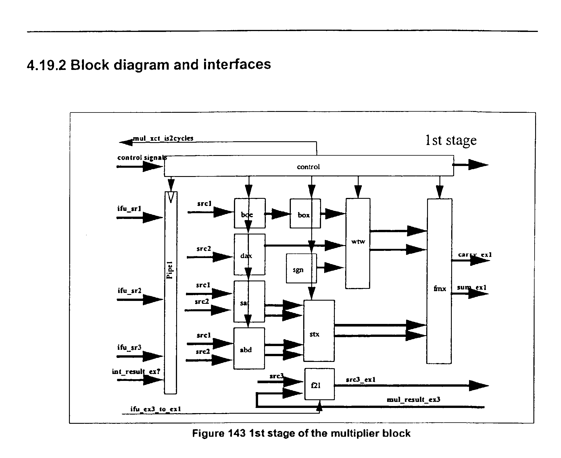
- the MUL function 360 for example, executes the multiplier related instructions, including SIMD (Single Instruction Multiple Data) integer multiplies. Many of the instructions complete in three cycles, but a few instructions may require four cycles to complete. Booth encoding algorithm may be used to perform the multiplication.
- SIMD Single Instruction Multiple Data
- the XCT 370 operates to buffer and broadcast the various control signals provided by IFU 210 that need to be duplicated for each execution block. It may control the block in the pipe as well, by keeping a small table of instruction position in the pipe. The XCT 370 may take into account the validation, stalling and invalidation signals.
- the XHW 340 has no complex instruction to handle, but it does handles instructions that are difficult to implement by re-using other blocks hardware.
- the instructions may have their own hardware for implementations, since each has a behavior that may not be matched in any other instruction.
- the MOVI, SHORI, and NSB instructions may be implemented in the XHW 340.
- XHW 340 may handle the move-like instructions, e.g., MOVI.
- the XHW 340 may not overload the IMA 320 critical path with extra muxes, and may avoid forcing zeroes on some source operands. And since it is a typically one cycle, 3 inputs operator, it can handle SHORI without any impact on the decoder critical path (no register swap). Since XHW 340 has a simple local opcode, it may also reduce decoder complexity for these instructions.
- FIG. 6 shows an example of a one cycle XHW instruction being executed in a pipeline of the present invention, where that instruction may be in a specific embodiment MOVI, SHORI, or NSB.
- cycle 405 shows the stages of the pipeline.
- the "D” Stage 410 shows the instruction in the cycle 405 just before execution.
- the control signal (xct_xhw_start_ex1 432)to start execution is then given, by the XCT 370.
- "E1" 412, "E2" 414, and “E3” 416 represent the exe1, exe2, and exe3 execution stages, i.e., cycles, respectively.
- the XHW 340 executes the instruction and gives the result, 434-438, all in one cycle, E1 412.
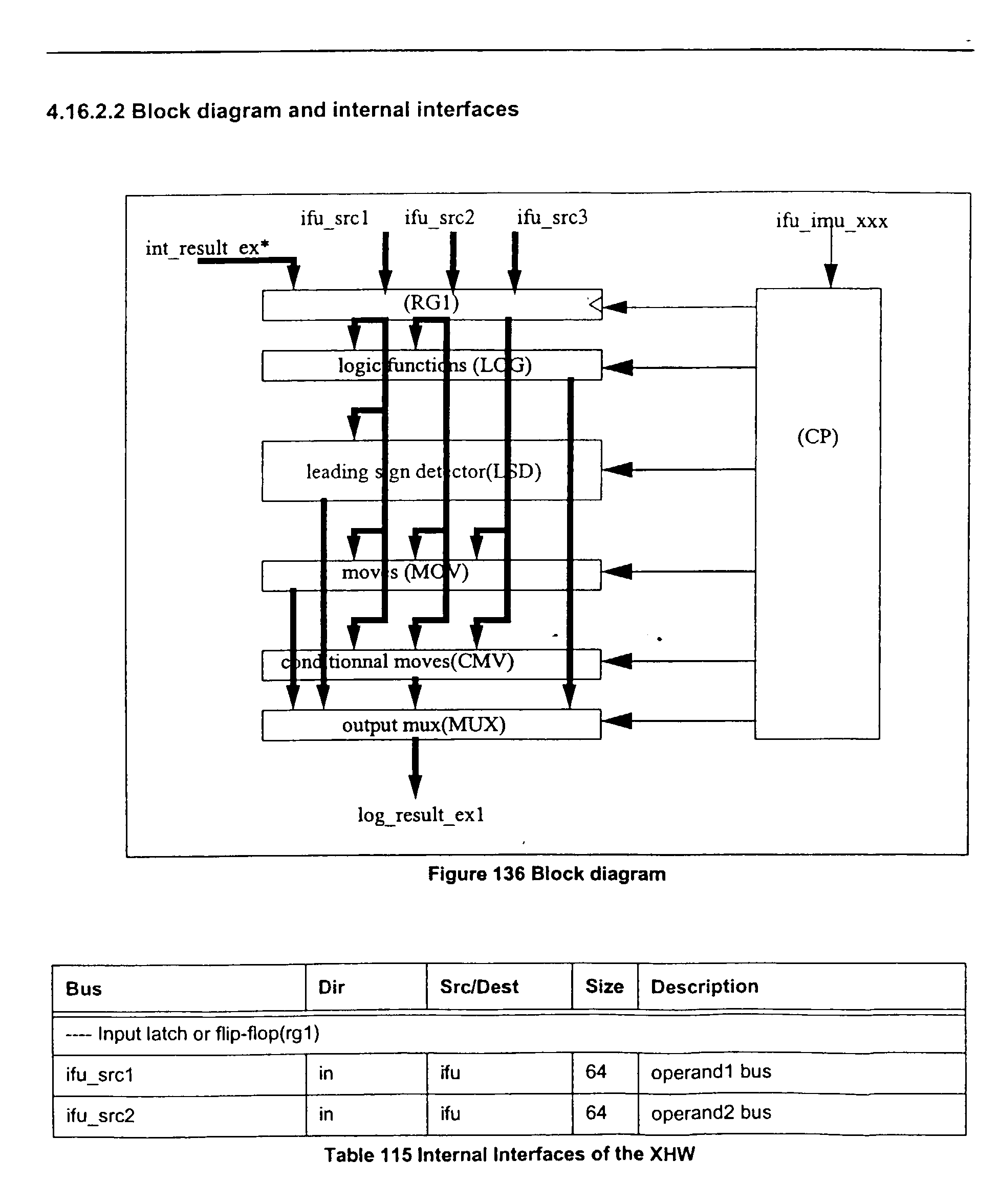
- FIG. 7 shows a block diagram of the one specific embodiment of the XHW 340 of the present invention.
- Table 7 illustrates examples of the external interfaces of the XHW 340.
- the XHW may include seven modules: RG1 530, LOG 540, LSD 550, MOV 560, CMV 570, MUX 580, and CP 590, which includes the control signals.
- Input latch or Flip-flop receives and stores the three source operands (ifu_src1, ifu_src2, and ifu_src3).
- Logic function(LOG 540) performs a logical AND, OR, ANDC, XOR and one result is selected.
- Leading sign counter(LSD 550) function i.e., NSB
- NSB Leading sign counter
- the sign is inverted when number is negative.
- the NSB may be, for example, a two stage process: bits are counted on a byte format for the lower 3 bits of the result, and then on the full double format, by byte, for the higher 3 bits of the result.
- the RTL code is given in Appendix 4.
- Move functions may include MOVI which may forward operand 2 to the result bus (Input source is already sign extended) and SHORI which may shift by 16 and abut.
- MOVI which may forward operand 2 to the result bus (Input source is already sign extended)
- SHORI which may shift by 16 and abut.
- the RTL code is given in Appendix 5.
- Conditional move may include compare instructions which select the entire or part of the source operands for generating the result, e.g., EQ and NE detect zero or non-zero operand 1.
Abstract
Description
- The invention relates generally to microprocessor/microcontroller architecture, and more particularly to an integer instruction set architecture.
- FIG. 1 illustrates the layering of a typical computer system, showing the tradeoff between using software versus hardware for microprocessor design and implementation. As FIG. 1 shows that shifting the microprocessor functions toward hardware typically increases speed 6, but reduces flexibility 8, while replacing hardware functions by software normally increases the flexibility of use 8, but at the cost of lower speed 6.
- The introduction of
microprograms 12 in firmware allowed more hardware functions to be done in software. The instruction sets, as a result, at theassembly language layer 16 became more complex. With the reduction in hardware costs, the balance moved back to hardware with some software functions being done in specialized hardware, e.g., floating point processors. This allowed an increase in performance. Thus, there is a continuing need to evaluate if a software function should be done in specialized hardware. - At the time hardware costs were coming down,
application programs 20 were becoming more complex and diverse. This , in part, drove a trend for more complexElectronic circuits 10 to execute theApplication programs 20 without loss in performance. For example,Application programs 20 using 16 bits, then 32 bits, drove or were in response toelectronic circuits 10 using 16 bit, 32 bit, or 64 bit words. ThusAssembly Language 16 instruction sets are being designed to handle the increase in application and hardware complexity. - Typical computer programs contain Integer Instructions which perform operations on integer numbers. For example, such operations may include adding, subtracting, comparing, loading a constant, shifting, moving, logically ORing, or logically NANDing, one or more operands into a result. Some of these integer operations were executed by
several Assembly Language 14 instructions. With the complex application programs being more widespread and with wider bus microprocessors, new instruction set architectures are needed to take full advantage of the increased software and hardware complexity. - Therefore, there is a need for an Integer instruction set which makes efficient use of the wider word, e.g., 64 bit architectures, to execute the more complex and diverse application programs. This may include designing some instructions to be executed on customized hardware to increase performance.
-
- FIG. 1 illustrates the different levels of prior art computer systems (PRIOR ART);
- FIG. 2 illustrates a specific embodiment of the SHORI instruction of the present invention;
- FIG. 3 illustrates a simplified example of the NSB instruction of the present invention;
- FIG. 4 illustrates an example block diagram of the Integer/Multimedia Unit of the present invention;
- FIG. 5 shows an example of a one cycle XHW instruction being executed in a pipeline of the present invention;
- FIG. 6 shows a block diagram of the one specific embodiment of the XHW of the present invention.
-
- In a specific embodiment a list of example Integer Instructions isgiven in Appendix 1. From the list of Integer Instructions, several are described to illustrate the features of the Integer Instruction set.
- One example is the loading of an arbitrary constant value. Instructions of this type typically have an immediate operand to allow a range of constant values to be encoded directly in the instruction. If the required constant does not fit in the space provided in the instruction, then the constant is loaded separately from the instruction.
- In a specific embodiment of the present invention the arbitrary constant is loaded by a series of immediate instructions, each including a part of the arbitrary constant value. For example, two instructions are provided for loading constants: MOVI loads a register with sign-extended 16-bit immediate value, and SHORI shifts its source operand 16 bits to the left, and then combines it with its 16-bit immediate value using an 'OR' operation. Constants, of arbitrary length, can be loaded by using a MOVI instruction followed by zero or more SHORI instructions. For example, for 32-bit instructions and a 64-bit destination register, sign-extended 16-bit constants can be loaded in 1 instruction (MOVI), sign-extended 32-bit constants in 2 instructions (MOVI then SHORI), sign-extended 48-bit constants in 3 instructions (MOVI then SHORI then another SHORI)and 64-bit constants in 4 instructions (MOVI then three SHORI's). Table 1 illustrates examples of formats for the MOVI and SHORI instructions.
Instruction Summary MOVI source, result move immediate SHORI source, result shift then "or" immediate - FIG. 2 illustrates a specific embodiment of the SHORI instruction of the present invention. FIG. 2 shows two registers A, as shown in various stages as:
A0 30, A1 50,A2 52, and A3 56, and RegisterB 54. Register A in step 1 is A0 30 and includes foursections C2 44, andC3 46. - The MOVI instruction loads
C1 42 intoA1 50 in thefourth location 38. The SHORI instruction performs several functions: shiftingC1 42 in register A, i.e.,A2 52, fromlocation 38 tolocation 36;loading register B 53 at theforth position 57 withC2 44 and zero extending it forlocations register B 53; and bit-wise "ORing"register A2 52 withregister B 53 to get the result, i.e., A3 58 in which C1 42 is inlocation 36 andC2 44 inlocation 38. Using another SHORI instruction,C3 46 may be loaded intoregister B 53 atlocation 57 and "OR'd" with a left shiftedA3 58, hence loading the constant 40 into register A. In another embodiment M1, M2 and M3 may be set to zero in A1 50. - Table 2 illustrates a detailed description of the MOVI instruction in a specific embodiment of the present invention. The microprocessor has 64 bit registers and the instructions are 32 bits in length. The MOVI instruction with opcode "110011", sign-extends the 16-bit immediate field "s" and stores the result in the register "d", i.e., Rd. The "r" field may be for four reserved bits.

- Table 3 illustrates a detailed description of the SHORI instruction in a specific embodiment of the present invention. The SHORI instruction with opcode "11010", left shifts the contents of register "w", i.e., Rw, by 16, performs a bitwise "OR" with the 16-bit immediate field "s", and stores the result in the register Rw. Rw may be, in this embodiment, 64 bits in length.

- Another example of where an integer instruction is used is in the counting of the sign bits in a signed integer number. An application were this may be useful is in the execution of a Digital Signal Processing (DSP) algorithm. The instruction set should include instructions which are efficient in the normalizing of signed fractional numbers so that their value lies in the range [0.5 - 1.0] and [-0.5 - -1.0]. The typical normalization function on a microprocessor chip does a series of left shift and compares. The value of an efficient normalization function may be seen by its use on a DSP chip. For example a standard normalization operation in a ITU speech coder may have a complexity weight of 30, indicating that it would consume 30 cycles on a DSP not supporting normalization as an instruction. In the G.729E speech coder the normalization function maybe called about 15000 times per second. Thus, as DSP algorithms may be used in
Application Programs 20, but not enough to need a separate DSP chip, an instruction which assists in normalization, such as the NSB instruction, would improve the performance of a general microprocessor executing a DSP algorithm. - In a specific embodiment of the present invention the NSB instruction counts the number of sign bits in its 64 bit source register, subtracts 1 and stores the result in its destination register. The number of sign bits is the number of consecutive bits, including the most significant bit and moving down towards the least significant bit, that have the same bit value. If the source register is then left shifted by the result of the NSB instruction, the result is normalized within the 64-bit signed number space.
- FIG. 3 illustrates a simplified example of the NSB instruction of the present invention; The integer "+2" 66 is shown in two's complement format for a byte, i.e., 8-bits, nibble (4-bits) 62 and
nibble 64. For this example, assume that the largest positive number is "+7" 72 withnibbles nibbles nibbles nibbles nibbles nibbles - Table 4 illustrates a detailed description of the NSB instruction in a specific embodiment of the present invention. The NSB instruction with split opcode "000000" and "1101" , counts the number of consecutive sign bits in register "m" (Rm), subtracts one and stores the result in register "d" (Rd). "r" stands for reserved bits and the registers are 64 bits. The algorithm given in Table 4 is an another specific embodiment of the NSB instruction.

- In a specific embodiment, the present invention may be implemented in a CPU having a core 200 unit at the zero or root hierarchy level. The
Core 200 may include six units at the hierarchy level 1. FIG. 4 illustrates an example of the top level partitioning of theCore 200. Table 5 describes the functions of each unit in the S5 core. The Instruction Flow Unit (IFU) 210 which includes processing the Integer instruction is further described inAppendix 2.Hierarchy Level Unit Acronym Description 0 S5 Core 200S5 Top level core block 1 Bus interface unit 205BIU Controls bus access to external modules such as peripheral modules and external memory interface. 1 Instruction Flow Unit 210IFU The front end of the CPU pipe: fetch, decode, issue & branch. Also contains mode B emulation. 1 Instruction multimedia unit 220IMU Handles all integer and multimedia instructions. The main CPU datapath. 1 Instruction cache Unit 230ICU Comprises the Instruction Cache and the Instruction Translation Lookaside Buffer (TLB) 1 Load Store Unit 240LSU Handles all memory instructions and Data cache control. 1 Data cache Unit 250DCU Comprises the Data Cache and the Data Translation Lookaside Buffer (TLB) 1 Floating Point Unit (not shown) FPU Detachable Floating point decoder, pipe control and execution pipe (not shown in FIG. 4). - FIG. 5 illustrates an example block diagram of the Integer/Multimedia Unit (IMU) 220. In a specific embodiment, an
IMU 220 may handle the cpu arithmetic instructions, including integer, multimedia arithmetic and logic instructions; load/store address calculation and out-of- range (maladdress) detection; branch and partial branch comparisions; and branch target address calculations. TheIMU 220 computations may occur during the first (exe1), second (exe2), or third (exe3) pipeline stages. Many of the sub-units have a one cycle execution time, while the multiplier may have a 3 cycle latency. TheIMU 220 in this embodiment may be a simple pipe. Unless aifu_imu_stall signal 312 or ifu_imu_invalidate signal 314 is received, data progress in the pipe each cycle without being blocked by dependent signals.TheIMU 220 gets many of its inputs from theIFU 210. Main signals may be source operands and opcode word. TheIMU 220 may send its result at exe1 and exe2 pipe stages (one and two cycles instructions), or at exe3 pipe stage(3 or 4 cycle instructions). - In a specific embodiment, the
IMU 220 includes seven units . Table 6 gives the description of the IMU blocks in FIG. 5.Appendix 3 has a detailed explanation of the embodiment of the IMU.Hierarchy Level Unit Function Acronym Description 2 adder ADA 316 integer and address adder 2 adder IMA 320 simd adder 2 selector XSL 330 exe1 exe2 exe3 result mux 2 extra exe hw XHW 340 special instructions support 2 shifter/ shuffle SHF 350 shifter and shuffle 2 multiplier MUL 360 integer and simd multiplier 2 control XCT 370 control block - The
ADA 316, for example, may do addressing of theIFU 210 orLSU 240 and integer addition, subtraction or comparison. TheADA 316 may include, a 64 bit adder . The second input may be inverted for substraction or compare. Range checking may also be done. - The
IMA 320, for example, may include two adders wherein each performs one 32-bit additions, two 16-bit additions or four 8-bit additions. Each type of addition may include a carry in, activated simultaneously for all additions. This allows byte processing, where the results may be 8 bit vectors. The second source operand may be inverted to allow subtraction and comparison. - The
XHW 340 in a specific embodiment handles instructions that are difficult to implement by re-using other blocks hardware. The instructions may have their own hardware for implementations since each have a behavior can not be matched in any other instruction. TheXHW 340 may include the MOVI, SHORI, and NSB instructions. - The
SHF 350, for example, performs the shift related instructions as well as the instructions involving the displacement of byte quantities in a 64 bit source. It executes many of them in one cycle (exe1) except for saturation's issued one cycle later (exe 2). It also muxes the saturation values if saturation commands are generated at exe2 stage. - Shuffle and byte displacement functions, are preferably performed by the
SHF 350 in 3 steps as well. First step creates control signals for the shuffle matrix.Step 2 moves the bytes. Last step muxes saturation value if required at exe3. - Saturation detection may be done separately by the
SHF 350. It uses the operands and masks from the shift paths and may produce the saturation commands for the second cycle (exe 2) of the shift and shuffle. - The
MUL function 360, for example, executes the multiplier related instructions, including SIMD (Single Instruction Multiple Data) integer multiplies. Many of the instructions complete in three cycles, but a few instructions may require four cycles to complete. Booth encoding algorithm may be used to perform the multiplication. - The
XCT 370 operates to buffer and broadcast the various control signals provided byIFU 210 that need to be duplicated for each execution block. It may control the block in the pipe as well, by keeping a small table of instruction position in the pipe. TheXCT 370 may take into account the validation, stalling and invalidation signals. - In a specific embodiment the
XHW 340 has no complex instruction to handle, but it does handles instructions that are difficult to implement by re-using other blocks hardware. The instructions may have their own hardware for implementations, since each has a behavior that may not be matched in any other instruction. The MOVI, SHORI, and NSB instructions may be implemented in theXHW 340. -
XHW 340 may handle the move-like instructions, e.g., MOVI. TheXHW 340 may not overload theIMA 320 critical path with extra muxes, and may avoid forcing zeroes on some source operands. And since it is a typically one cycle, 3 inputs operator, it can handle SHORI without any impact on the decoder critical path (no register swap). SinceXHW 340 has a simple local opcode, it may also reduce decoder complexity for these instructions. - FIG. 6 shows an example of a one cycle XHW instruction being executed in a pipeline of the present invention, where that instruction may be in a specific embodiment MOVI, SHORI, or NSB. In FIG. 6 "cycle" 405 shows the stages of the pipeline. The "D"
Stage 410 shows the instruction in thecycle 405 just before execution. The control signal (xct_xhw_start_ex1 432)to start execution is then given, by theXCT 370. "E1" 412, "E2" 414, and "E3" 416, represent the exe1, exe2, and exe3 execution stages, i.e., cycles, respectively. TheXHW 340 executes the instruction and gives the result, 434-438, all in one cycle,E1 412. - FIG. 7 shows a block diagram of the one specific embodiment of the
XHW 340 of the present invention. Table 7 illustrates examples of the external interfaces of theXHW 340.Bus Dir Src/Dest Size Time Description ---- Source operand busses ifu_src1 510 in ifu 64 ck1** operand1 bus ifu_src2 512 in ifu 64 ck1** operand2 bus ifu_src3 514 in ifu 64 ck1** operand3 bus int_result_ex1 516 in xsl 64 ck1** internal forwarded result 1 int_result_ex2 516in xsl 64 ck1** internal forwarded result 2int_result_ex3 516in xsl 64 ck1** internal forwarded result 3int_src1_from 518 in xct 4 ck1** source 1 selection int_src2_from 518 in xct 4 ck1* source 2 selectionint_src3_from 518 in xct 4 ck1* source 3 selection---- Instruction input signals xct_xhw_opc 518 in xct 13 ck1* xhw opcode ---- Pipe control input signals xct_xhw_start_ex1 518 in xct 1 ck1** xhw starts ex1 xct_xhw_shf_ex1_comp1 518 in xct 1 ck1* ex1 gets xhw data ---- Output data xhw_result_ex1 520 out ifu 64 ck1* exe1 result xhw_result_ex1_valid (not shown) out ifu 1 ck1 exe1 result is valid - In a specific embodiment the XHW may include seven modules:
RG1 530,LOG 540,LSD 550,MOV 560,CMV 570,MUX 580, andCP 590, which includes the control signals. - Input latch or Flip-flop (RG1 530) receives and stores the three source operands (ifu_src1, ifu_src2, and ifu_src3).
- Logic function(LOG 540) performs a logical AND, OR, ANDC, XOR and one result is selected.
- Leading sign counter(LSD 550) function, i.e., NSB, is based on a leading zero counter. The sign is inverted when number is negative. The NSB may be, for example, a two stage process: bits are counted on a byte format for the lower 3 bits of the result, and then on the full double format, by byte, for the higher 3 bits of the result. The RTL code is given in Appendix 4.
- Move functions (MOV 560) may include MOVI which may forward
operand 2 to the result bus (Input source is already sign extended) and SHORI which may shift by 16 and abut. The RTL code is given in Appendix 5. - For SHORI : the 16-bit immediate constant value is zero extended and the rg1_data3 is 16-bit left shifted, then these two values are "OR'd". An example of an RTL statement that does this is: (48'b0,rg1_data2[15:0]} {rg1_data3[47:0],16'b0}, which is equivalent to {rg1_data3[47:0], rg1_data2[15:0]} given in Appendix 5.
- Conditional move (CMV 570)may include compare instructions which select the entire or part of the source operands for generating the result, e.g., EQ and NE detect zero or non-zero operand 1.
- There may be an output mux(MUX 580) which selects the result.
- In the foregoing specification, the invention has been described with reference to specific exemplary embodiments thereof. Other embodiments will be apparent to those of ordinary skill in the art. For example, the instructions may be 16 or 64 bits in length and the microprocessor may operate with 16, 32, or 128 bit busses and words. Thus, it is evident that various modifications and changes may be made thereunto without departing from the broader spirit and scope of the invention as set forth in the appended claims and their full scope of equivalents.


Claims (23)
- A method for loading a constant number into a memory location, wherein the memory location comprises a plurality of sequential sections, comprising:segmenting the constant number into a plurality of parts;loading a first part of the plurality of parts into a first section of the plurality of sequential sections;moving the first part in the first section to a second section of the plurality of sequential sections; andloading a second part of the plurality of parts into the first section.
- The method of claim 1 wherein the memory location comprises a register.
- A method for loading a constant number comprising a plurality of parts, into a destination memory location, comprising:shifting a first memory location comprising a plurality of sequential sections by a total number of bits in a section of the first memory location;loading a part of the constant number into a section of a second memory location comprising a second plurality of sequential sections;determining a result by logically combining the first memory location and the second memory location; andstoring the result in the destination memory location.
- The method of claim 3 wherein the logically combining is bit-wise ORing.
- The method of claim 3 wherein the shifting is left-shifting with zeros being shifted in at the right end of the first memory location.
- The method of claim 3 further comprising loading a first part of the constant number into the first memory location before the shifting of the first memory location.
- The method of claim 6 wherein loading a first part of the constant number comprises sign-extending the first part in the first memory location.
- The method of claim 3 wherein the loading a part of the constant number into a section of a second memory location comprises loading a second part of the constant number into a first section of the second memory location and zero-extending the second part.
- A method for loading a constant number into a register from a plurality of instructions, wherein an instruction data field from the plurality of instructions comprises a part of the constant number, comprising:loading a first part of the register with a first instruction data field from the plurality of instructions;moving the first instruction data field from the first part of the register to a second part of the register, such that the second part of the register comprises the first instruction data field and the first part of the register is zero-filled;performing a logical OR operation on a second instruction data field from the plurality of instructions with the first part of the register to produce a first result; andstoring the first result in the first part of the register.
- The method of claim 9 wherein the shifting the first instruction data field, performing a logical OR operation, and storing the first result are processed in a cycle.
- The method of claim 9 wherein the register is 64 bits in length, and each instruction data field comprises an intermediate field of upto 16 bits in length.
- The method of claim 9 further comprising:moving the first instruction data field from the second part of the register to a third part of the register, such that the third part of the register comprises the first instruction data field;moving the first result from the first part of the register to the second part of the register, such that the second part of the register comprises the first result, and the first part of the register is zero-filled;performing a logical OR operation on a third instruction data field from the plurality of instructions and the first part of the register to produce a second result; andstoring the second result in the first part of the register.
- The method of claim 12 wherein the moving the first instruction data field, moving the first result, performing a logical OR operation, and storing the second result are processed in a timing cycle.
- A method, using a computer, for determining a number of sign bits comprising:counting a total number of sign bits in the binary number stored in a first memory location;determining a result by subtracting one from the total number; andstoring the result in a second memory location;
- The method of claim 14, wherein the sign bits are counted on a byte format for a first plurality of bits of the result, and then by byte on a full double format for a second plurality of bits of the result.
- The method of claim 14, wherein the result is determined in one pipeline execution cycle.
- A method, using a computer, for normalizing a binary number comprising:counting a total number of sign bits in the binary number stored in a first memory location;determining a result by subtracting one from the total number;storing the result in a second memory location; andobtaining a normalized number by shifting the binary number by the result.
- The method of claim 17, wherein one instruction comprises:
counting the total number of sign bits; determining the result by subtracting one from the total number; and storing the result in the second memory location. - The method of claim 17, wherein the sign bits are counted on a byte format for a lower plurality of bits of the result, and then by byte on a full double format for a higher plurality of bits of the result.
- The method of claim 17, wherein counting the total number of sign bits comprises counting the total number of consecutive bits with the same bit value as a most significant bit, wherein the counting starts at the most significant bit and continues to the least significant bit with the same bit value as the most significant bit.
- The method of claim 17, wherein the normalized number is used in a Digital Signal Processing (DSP) application.
- An instruction in a computer system comprising:determining a result by counting the number of consecutive sign bits in a first register;subtracting one from the result; andstoring the result in a second register.
- The method of claim 22, wherein the instruction comprises 32 bits and the first and second registers comprise 64 bits.
Applications Claiming Priority (2)
| Application Number | Priority Date | Filing Date | Title |
|---|---|---|---|
| US41068399A | 1999-10-01 | 1999-10-01 | |
| US410683 | 1999-10-01 |
Publications (2)
| Publication Number | Publication Date |
|---|---|
| EP1089166A2 true EP1089166A2 (en) | 2001-04-04 |
| EP1089166A3 EP1089166A3 (en) | 2004-10-20 |
Family
ID=23625785
Family Applications (1)
| Application Number | Title | Priority Date | Filing Date |
|---|---|---|---|
| EP00308584A Withdrawn EP1089166A3 (en) | 1999-10-01 | 2000-09-29 | An integer instruction set architecture and implementation |
Country Status (4)
| Country | Link |
|---|---|
| EP (1) | EP1089166A3 (en) |
| JP (1) | JP2001142695A (en) |
| KR (1) | KR20010050804A (en) |
| TW (1) | TW497074B (en) |
Cited By (2)
| Publication number | Priority date | Publication date | Assignee | Title |
|---|---|---|---|---|
| GB2529777A (en) * | 2014-02-12 | 2016-03-02 | Imagination Tech Ltd | Processor with granular add immediates capability and methods |
| US10866817B2 (en) | 2016-03-14 | 2020-12-15 | Samsung Electronics Co.. Ltd. | Computing system, and driving method and compiling method thereof |
Families Citing this family (4)
| Publication number | Priority date | Publication date | Assignee | Title |
|---|---|---|---|---|
| JP3857614B2 (en) | 2002-06-03 | 2006-12-13 | 松下電器産業株式会社 | Processor |
| US7373432B2 (en) | 2002-10-31 | 2008-05-13 | Lockheed Martin | Programmable circuit and related computing machine and method |
| US7809982B2 (en) | 2004-10-01 | 2010-10-05 | Lockheed Martin Corporation | Reconfigurable computing machine and related systems and methods |
| KR102270790B1 (en) | 2014-10-20 | 2021-06-29 | 삼성전자주식회사 | Method and apparatus for data processing |
Citations (3)
| Publication number | Priority date | Publication date | Assignee | Title |
|---|---|---|---|---|
| EP0395348A2 (en) * | 1989-04-28 | 1990-10-31 | Apple Computer, Inc. | Method and apparatus for multi-gauge computation |
| EP0897147A2 (en) * | 1997-06-16 | 1999-02-17 | Matsushita Electric Industrial Co., Ltd. | Constant reconstructing processor which supports reductions in code size |
| EP1003094A2 (en) * | 1998-11-20 | 2000-05-24 | Asia Design Co., Ltd | Central processing unit having a data extension instruction |
-
2000
- 2000-09-28 JP JP2000335190A patent/JP2001142695A/en active Pending
- 2000-09-29 EP EP00308584A patent/EP1089166A3/en not_active Withdrawn
- 2000-09-30 TW TW089120404A patent/TW497074B/en not_active IP Right Cessation
- 2000-10-02 KR KR1020000057804A patent/KR20010050804A/en not_active Application Discontinuation
Patent Citations (3)
| Publication number | Priority date | Publication date | Assignee | Title |
|---|---|---|---|---|
| EP0395348A2 (en) * | 1989-04-28 | 1990-10-31 | Apple Computer, Inc. | Method and apparatus for multi-gauge computation |
| EP0897147A2 (en) * | 1997-06-16 | 1999-02-17 | Matsushita Electric Industrial Co., Ltd. | Constant reconstructing processor which supports reductions in code size |
| EP1003094A2 (en) * | 1998-11-20 | 2000-05-24 | Asia Design Co., Ltd | Central processing unit having a data extension instruction |
Non-Patent Citations (1)
| Title |
|---|
| MAY D ET AL NORTH ATLANTIC TREATY ORGANIZATION: "THE TRANSPUTER" NEURAL COMPUTERS. NEUSS, SEPT. 28 - OCT. 2, 1987, PROCEEDINGS OF THE NATO ADVANCED WORKSHOP ON NEURAL COMPUTERS, BERLIN, SPRINGER, DE, 28 September 1987 (1987-09-28), pages 477-486, XP000410440 * |
Cited By (4)
| Publication number | Priority date | Publication date | Assignee | Title |
|---|---|---|---|---|
| GB2529777A (en) * | 2014-02-12 | 2016-03-02 | Imagination Tech Ltd | Processor with granular add immediates capability and methods |
| GB2529777B (en) * | 2014-02-12 | 2016-08-03 | Imagination Tech Ltd | Processor with granular add immediates capability and methods |
| US10768930B2 (en) | 2014-02-12 | 2020-09-08 | MIPS Tech, LLC | Processor supporting arithmetic instructions with branch on overflow and methods |
| US10866817B2 (en) | 2016-03-14 | 2020-12-15 | Samsung Electronics Co.. Ltd. | Computing system, and driving method and compiling method thereof |
Also Published As
| Publication number | Publication date |
|---|---|
| TW497074B (en) | 2002-08-01 |
| JP2001142695A (en) | 2001-05-25 |
| EP1089166A3 (en) | 2004-10-20 |
| KR20010050804A (en) | 2001-06-25 |
Similar Documents
| Publication | Publication Date | Title |
|---|---|---|
| US8386755B2 (en) | Non-atomic scheduling of micro-operations to perform round instruction | |
| USRE38679E1 (en) | Data processor and method of processing data | |
| US5450607A (en) | Unified floating point and integer datapath for a RISC processor | |
| US5418736A (en) | Optimized binary adders and comparators for inputs having different widths | |
| US5619664A (en) | Processor with architecture for improved pipelining of arithmetic instructions by forwarding redundant intermediate data forms | |
| US7917568B2 (en) | X87 fused multiply-add instruction | |
| GB2267589A (en) | Performing integer and floating point division using a single SRT divider | |
| CN102576302B (en) | Microprocessor and method for enhanced precision sum-of-products calculation on a microprocessor | |
| US6341300B1 (en) | Parallel fixed point square root and reciprocal square root computation unit in a processor | |
| US8046400B2 (en) | Apparatus and method for optimizing the performance of x87 floating point addition instructions in a microprocessor | |
| EP2309383A1 (en) | System with wide operand architecture and method | |
| JP5719341B2 (en) | Mechanism for fast detection of overshifts in floating point units | |
| US5991863A (en) | Single carry/borrow propagate adder/decrementer for generating register stack addresses in a microprocessor | |
| US5815420A (en) | Microprocessor arithmetic logic unit using multiple number representations | |
| EP0772809B1 (en) | Method for performing a "rotate through carry" operation | |
| US6055628A (en) | Microprocessor with a nestable delayed branch instruction without branch related pipeline interlocks | |
| EP1089166A2 (en) | An integer instruction set architecture and implementation | |
| US6078940A (en) | Microprocessor with an instruction for multiply and left shift with saturate | |
| EP0772817B1 (en) | EXECUTION UNIT ARCHITECTECTURE TO SUPPORT x86 INSTRUCTION SET AND x86 SEGMENTED ADDRESSING | |
| US5822786A (en) | Apparatus and method for determining if an operand lies within an expand up or expand down segment | |
| KR100431726B1 (en) | Method for performing signed division | |
| US5754460A (en) | Method for performing signed division | |
| US8005884B2 (en) | Relaxed remainder constraints with comparison rounding | |
| US6393554B1 (en) | Method and apparatus for performing vector and scalar multiplication and calculating rounded products | |
| US6128725A (en) | Microprocessor with an instruction for setting or clearing a bit field |
Legal Events
| Date | Code | Title | Description |
|---|---|---|---|
| PUAI | Public reference made under article 153(3) epc to a published international application that has entered the european phase |
Free format text: ORIGINAL CODE: 0009012 |
|
| AK | Designated contracting states |
Kind code of ref document: A2 Designated state(s): AT BE CH CY DE DK ES FI FR GB GR IE IT LI LU MC NL PT SE |
|
| AX | Request for extension of the european patent |
Free format text: AL;LT;LV;MK;RO;SI |
|
| RIN1 | Information on inventor provided before grant (corrected) |
Inventor name: KUO, LIANG CHENG Inventor name: MANDAVILLI, SRINIVAS Inventor name: KRISHNAN, SIVARAM |
|
| PUAL | Search report despatched |
Free format text: ORIGINAL CODE: 0009013 |
|
| AK | Designated contracting states |
Kind code of ref document: A3 Designated state(s): AT BE CH CY DE DK ES FI FR GB GR IE IT LI LU MC NL PT SE |
|
| AX | Request for extension of the european patent |
Extension state: AL LT LV MK RO SI |
|
| AKX | Designation fees paid |
Designated state(s): DE FR GB IT NL |
|
| STAA | Information on the status of an ep patent application or granted ep patent |
Free format text: STATUS: THE APPLICATION IS DEEMED TO BE WITHDRAWN |
|
| 18D | Application deemed to be withdrawn |
Effective date: 20050401 |